

Developing and Applying a Double Triangular Damping Device with Equivalent Negative Stiffness for Base-Isolated Buildings


Abstract
:1. Introduction
2. Mechanism and Experimental Tests of a Triangular Damping System
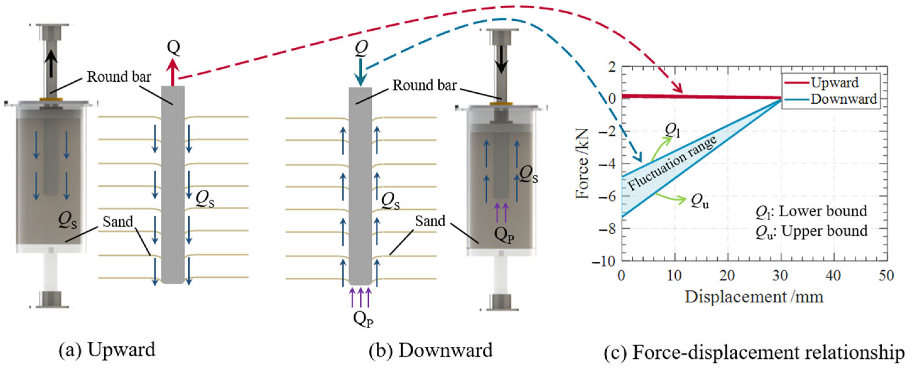
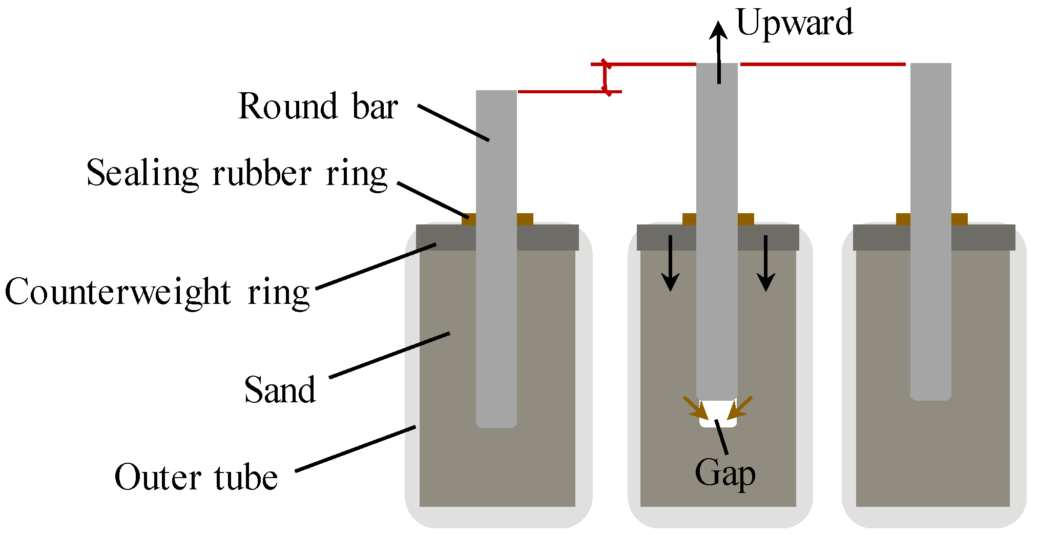
2.1. Mechanism of the Triangular Damping System
2.2. Experimental Tests of the Triangular Damping System
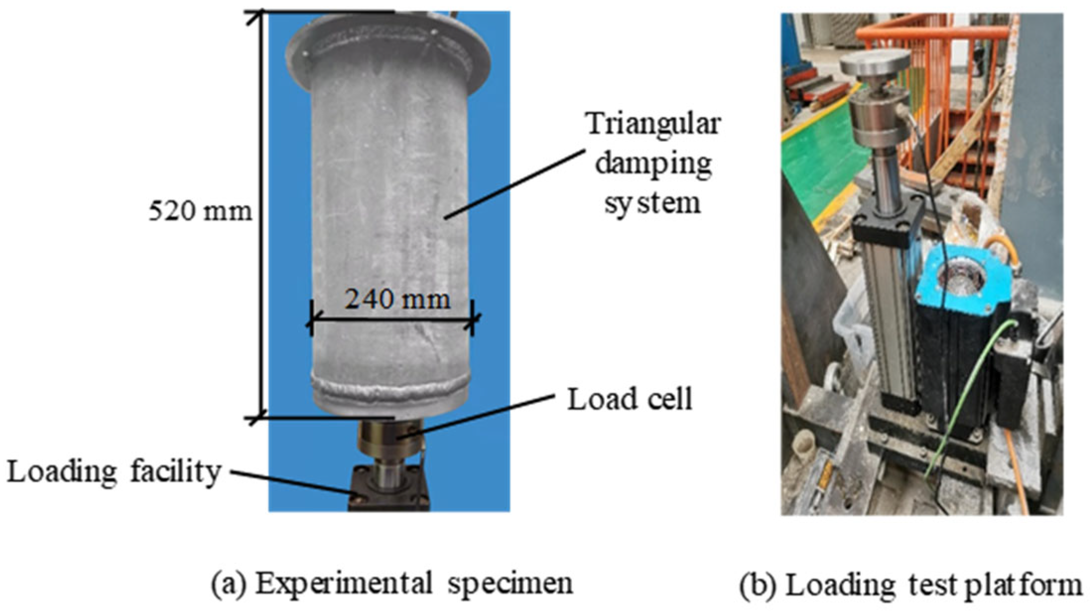
2.2.1. Experimental Specimen
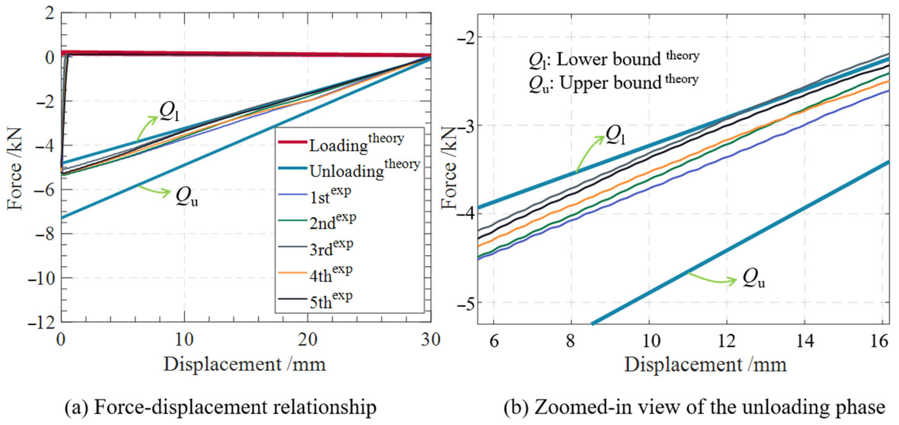
2.2.2. Experimental Results
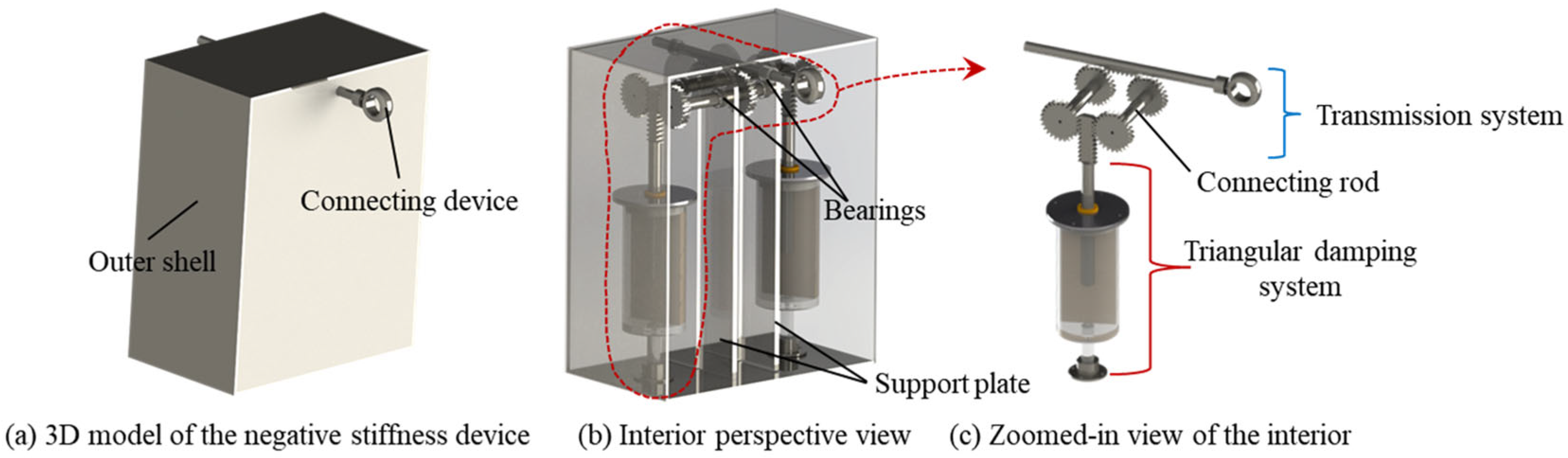
3. Mechanism and Analysis of DTD Device
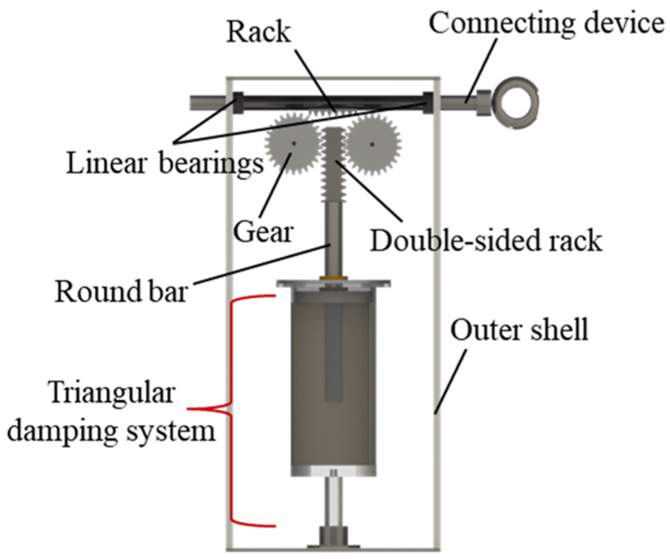
3.1. Mechanism of the DTD Device
3.2. Transmission System
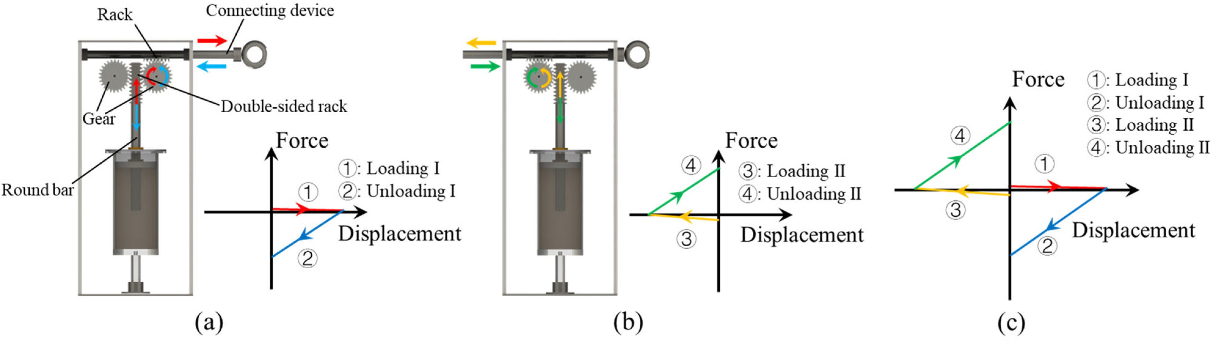
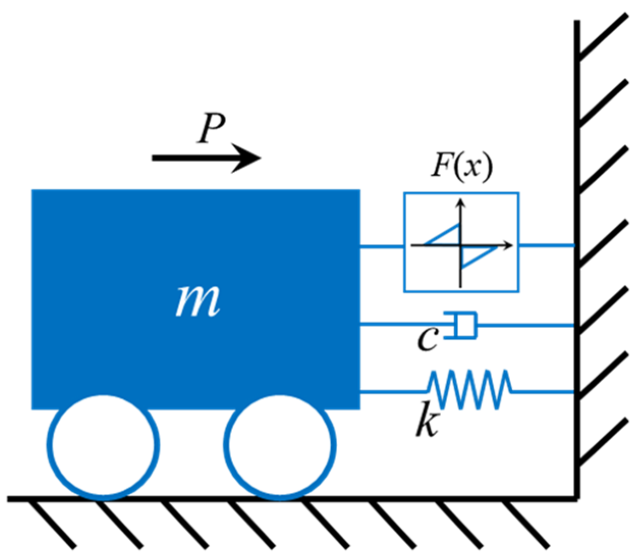
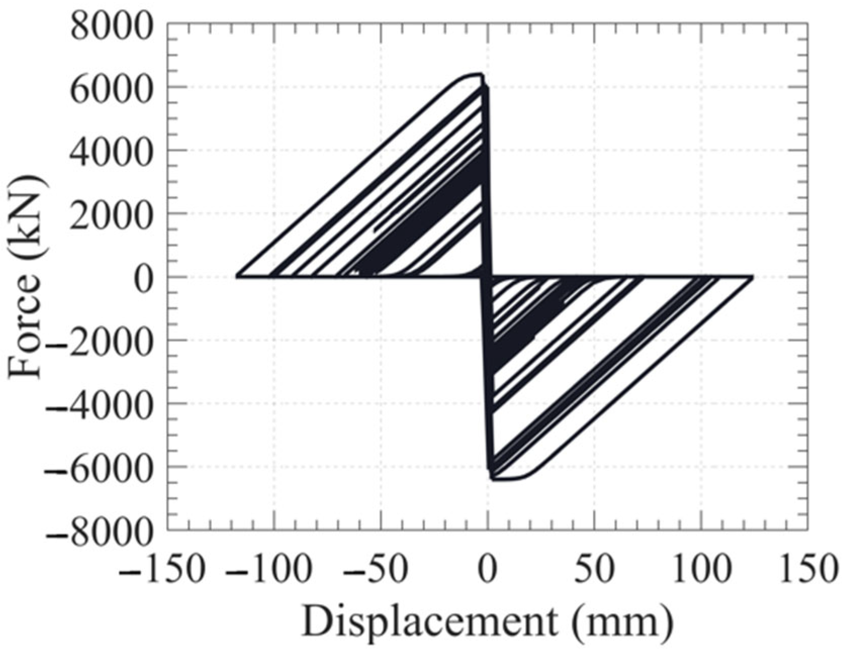
3.3. Hysteresis Characteristic Analysis of the DTD
4. Seismic Control Performance of the DTD Isolation System
4.1. Numerical Example
4.2. Simulation Results
5. Conclusions
- (1)
- A passive triangular damping system was proposed. A mechanical model was developed, and its hysteretic behavior was examined using experimental tests, which verified the effectiveness of the proposed triangular damping system.
- (2)
- By coordinating the transmission system with the triangular damping system, an equivalent negative stiffness device was developed, which generated a damping effect named double triangular damping (DTD).
- (3)
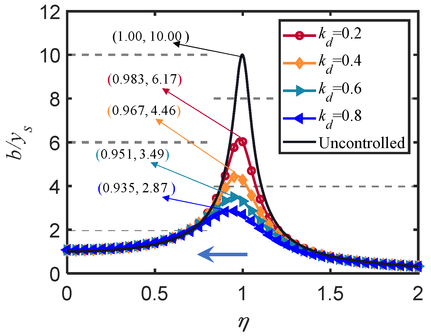
- Frequency response analysis of the SDOF system revealed that DTD was able to reduce the natural vibration frequency and control the displacement response of the system. This demonstrated that DTD is a type of damping with equivalent negative stiffness, and the corresponding expressions were presented.
- (4)
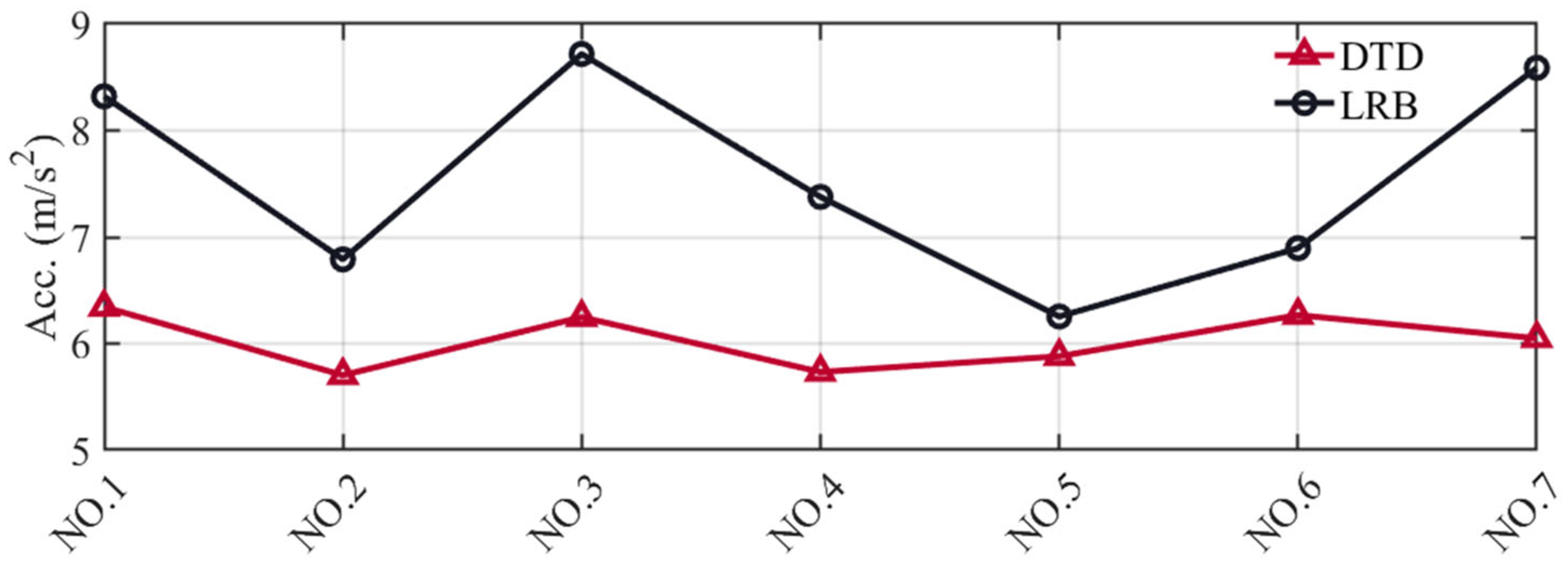
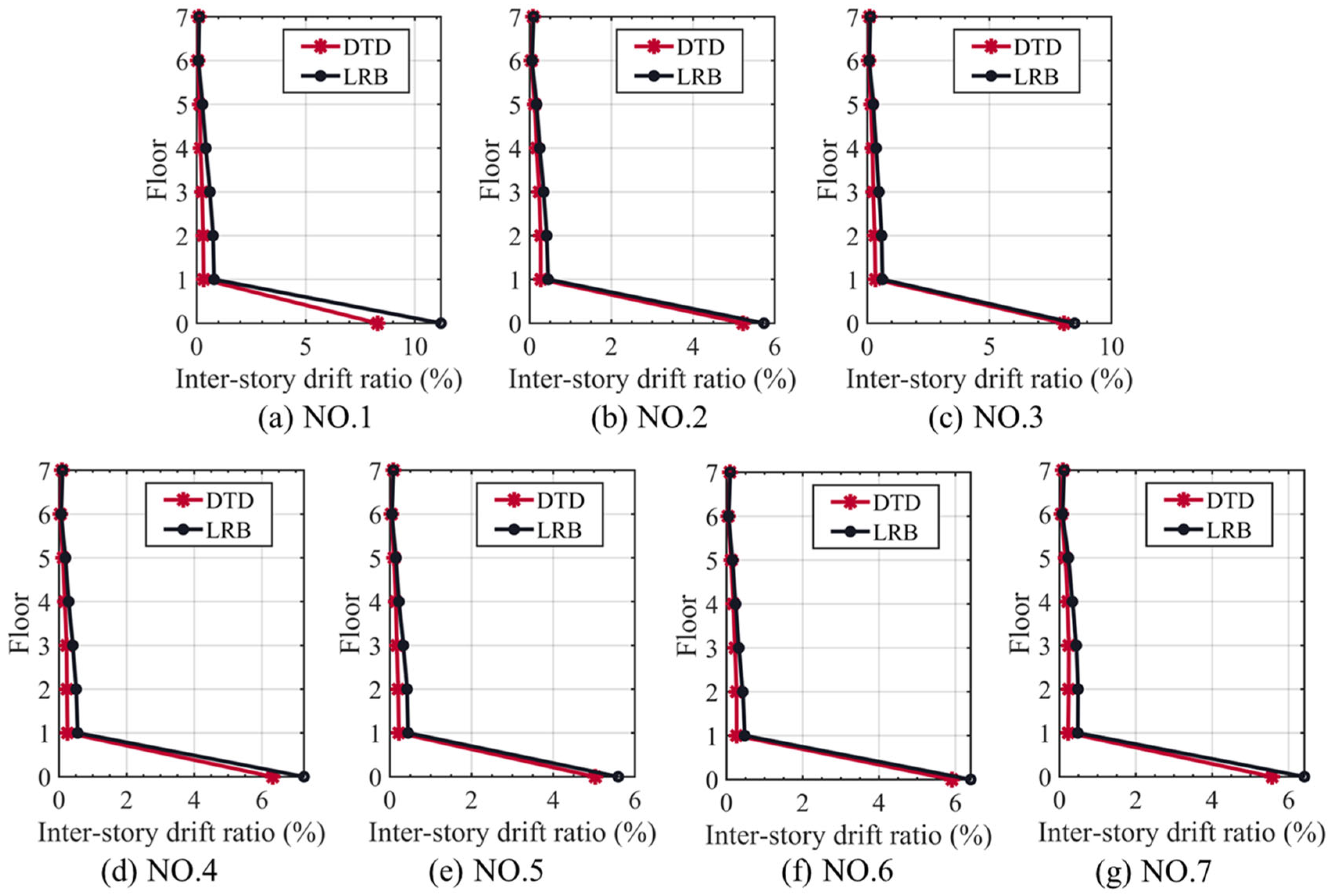
- Numerical simulation results revealed that DTD-controlled construction can improve the effectiveness of structural isolation without amplifying the displacement response of the isolation layer. Compared with LRB-controlled structures, DTD-controlled structures reduced the maximum isolator displacement and rooftop acceleration by 11.96% and 19.30%, respectively, on average for the seven seismic motions considered.
Author Contributions
Funding
Data Availability Statement
Conflicts of Interest
References
- Gatti, G.; Brennan, M.J.; Tang, B. Some diverse examples of exploiting the beneficial effects of geometric stiffness nonlinearity. Mech. Syst. Signal Process. 2019, 125, 4–20. [Google Scholar] [CrossRef]
- Hong, N.; Zhao, Z.; Du, Y.; Chen, Q. Energy spectra and performance assessment of isolated structures with a negative stiffness amplification system. Soil Dyn. Earthq. Eng. 2023, 169, 107857. [Google Scholar] [CrossRef]
- Zhang, Y.; Liu, Q.; Lei, Y.; Cao, J.; Liao, W.-H. Halbach high negative stiffness isolator: Modeling and experiments. Mech. Syst. Signal Process. 2023, 188, 110014. [Google Scholar] [CrossRef]
- Dong, G.; Zhang, X.; Xie, S.; Yan, B.; Luo, Y. Simulated and experimental studies on a high-static-low-dynamic stiffness isolator using magnetic negative stiffness spring. Mech. Syst. Signal Process. 2017, 86, 188–203. [Google Scholar] [CrossRef]
- Xu, Y.W.; Xu, Z.D.; Guo, Y.Q.; Huang, X.H.; Zhang, J.; Zhao, Y.L.; Yang, Y.; Zhu, C.; Zhou, M. Single input magnetorheological pseudo negative stiffness control for bridge stay cables. Smart Mater. Struct. 2020, 30, 015032. [Google Scholar] [CrossRef]
- Weber, F.; Boston, C. Clipped viscous damping with negative stiffness for semi-active cable damping. Smart Mater. Struct. 2011, 20, 045007. [Google Scholar] [CrossRef]
- Xu, Y.W.; Xu, Z.D.; Guo, Y.Q.; Zhou, M.; Zhao, Y.L.; Yang, Y.; Dai, J.; Zhang, J.; Zhu, C.; Ji, B.H.; et al. A programmable pseudo negative stiffness control device and its role in stay cable vibration control. Mech. Syst. Signal Process. 2022, 173, 109054. [Google Scholar] [CrossRef]
- Zhou, P.; Liu, M.; Li, H. Optimized negative stiffness damper with flexible support for stay cables. Struct. Control Health Monit. 2021, 28, e2717. [Google Scholar] [CrossRef]
- Høgsberg, J. The role of negative stiffness in semi-active control of magneto-rheological dampers. Struct. Control Health Monit. 2011, 18, 289–304. [Google Scholar] [CrossRef]
- Sato, E.; Furukawa, S.; Kakehi, A.; Nakashima, M. Full-scale shaking table test for examination of safety and functionality of base-isolated medical facilities. Earthq. Eng. Struct. Dyn. 2011, 40, 1435–1453. [Google Scholar] [CrossRef]
- Ibrahim, R.A. Recent advances in nonlinear passive vibration isolators. J. Sound Vib. 2008, 314, 371–452. [Google Scholar] [CrossRef]
- Lu, L.Y.; Lin, G.L. Improvement of near-fault seismic isolation using a resettable variable stiffness damper. Eng. Struct. 2009, 31, 2097–2114. [Google Scholar] [CrossRef]
- Efstathiades, G.J.; Williams, C.J.H. Vibration isolation using non-linear springs. Int. J. Mech. Sci. 1967, 9, 27–44. [Google Scholar] [CrossRef]
- Zheng, W.; Wang, H.; Tan, P.; Li, J.; Liu, Y. Numerical modeling and experimental validation of Sliding-LRBs considering hysteretic strength degradation. Eng. Struct. 2022, 262, 114374. [Google Scholar] [CrossRef]
- Zheng, W.; Tan, P.; Zhang, Z.; Wang, H.; Sun, Z. Damping enhanced novel re-centering seismic isolator incorporating superelastic SMA for response control of bridges under near-fault earthquakes. Smart Mater. Struct. 2022, 31, 065015. [Google Scholar] [CrossRef]
- Zheng, W.; Tan, P.; Li, J.; Wang, H.; Liu, Y.; Yang, K. Seismic performance upgrading of bridges using superelastic pendulum isolators with variable stiffness considering temperature effects. Eng. Struct. 2023, 275, 115244. [Google Scholar] [CrossRef]
- Shang, J.; Tan, P.; Zhang, Y.; Han, J.; Qin, J. Experimental and analytical investigation of variable friction pendulum isolator. Eng. Struct. 2021, 243, 112575. [Google Scholar] [CrossRef]
- Zheng, W.; Tan, P.; Li, J.; Wang, H.; Liu, Y.; Xian, Z. Superelastic conical friction pendulum isolator for seismic isolation of bridges under near-fault ground motions. Struct. Control. Health Monit. 2023, 2023, 5497731. [Google Scholar] [CrossRef]
- Zheng, W.; Tan, P.; Li, J.; Wang, H.; Liu, Y.; Xian, Z. Superelastic pendulum isolator with multi-stage variable curvature for seismic resilience enhancement of cold-regional bridges. Eng. Struct. 2023, 284, 115960. [Google Scholar] [CrossRef]
- Chen, X.; Ikago, K.; Guan, Z.; Li, J.; Wang, X. Lead-rubber-bearing with negative stiffness springs (LRB-NS) for base-isolation seismic design of resilient bridges: A theoretical feasibility study. Eng. Struct. 2022, 266, 114601. [Google Scholar] [CrossRef]
- Zheng, W.; Tan, P.; Liu, Y.; Wang, H.; Chen, H. Multi-stage superelastic variable stiffness pendulum isolation system for seismic response control of bridges under near-fault earthquakes. Struct. Control Health Monit. 2022, 29, e3114. [Google Scholar] [CrossRef]
- Chen, Q.; Hong, N.; Zhang, T.; Zhao, Z. Experiment-based performance evaluation framework for isolated structures in underground subway station-soil-aboveground structure interaction system under seismic excitations. J. Build. Eng. 2022, 56, 104790. [Google Scholar] [CrossRef]
- Palazzo, B.; Petti, L.; de Ligio, M. Response of base isolated systems equipped with tuned mass dampers to random excitations. J. Struct. Control 2007, 4, 9–22. [Google Scholar] [CrossRef]
- Taniguchi, T.; Der Kiureghian, A.; Melkumyan, M. Effect of tuned mass damper on displacement demand of base-isolated structures. Eng. Struct. 2008, 30, 3478–3488. [Google Scholar] [CrossRef]
- Kapasakalis, K.A.; Antoniadis, I.A.; Sapountzakis, E.J. Performance assessment of the KDamper as a seismic absorption base. Struct. Control Health Monit. 2020, 27, e2482. [Google Scholar] [CrossRef]
- Kapasakalis, K.A.; Antoniadis, I.A.; Sapountzakis, E.J. Constrained optimal design of seismic base absorbers based on an extended KDamper concept. Eng. Struct. 2021, 226, 111312. [Google Scholar] [CrossRef]
- Kalogerakou, M.E.; Kapasakalis, K.A.; Antoniadis, I.A.; Sapountzakis, E.J. Vertical seismic protection of structures with inerter-based negative stiffness absorbers. Bull. Earthq. Eng. 2022, 21, 1439–1480. [Google Scholar] [CrossRef]
- Su, N.; Bian, J.; Peng, S.; Chen, Z.; Xia, Y. Balancing static and dynamic performances of TMD with negative stiffness. Int. J. Mech. Sci. 2023, 243, 108068. [Google Scholar] [CrossRef]
- Zhou, S.; Jean-Mistral, C.; Chesne, S. Closed-form solutions to optimal parameters of dynamic vibration absorbers with negative stiffness under harmonic and transient excitation. Int. J. Mech. Sci. 2019, 157–158, 528–541. [Google Scholar] [CrossRef]
- Wang, M.; Sun, F.F.; Nagarajaiah, S. Simplified optimal design of MDOF structures with negative stiffness amplifying dampers based on effective damping. Struct. Des. Tall Spec. Build. 2019, 28, e1664. [Google Scholar] [CrossRef]
- Walsh, K.K.; Sallar, G.; Haftman, J.T.; Steinberg, E.P. Resetting passive stiffness damper with passive negative stiffness device for seismic protection of structures. Struct. Control Health Monit. 2021, 28, e2774. [Google Scholar] [CrossRef]
- Chen, L.; Liu, Z.; Zou, Y.; Wang, M.; Nagarajaiah, S.; Sun, F.; Sun, L. Practical negative stiffness device with viscoelastic damper in parallel or series configuration for cable damping improvement. J. Sound Vib. 2023, 560, 117757. [Google Scholar] [CrossRef]
- Chen, P.; Wang, B.; Dai, K.; Li, T. Analytical and numerical investigations of base isolation system with negative stiffness devices. Eng. Struct. 2022, 268, 114799. [Google Scholar] [CrossRef]
- Li, H.; Li, Y.; Li, J. Negative stiffness devices for vibration isolation applications: A review. Adv. Struct. Eng. 2020, 23, 1739–1755. [Google Scholar] [CrossRef]
- Chowdhury, S.; Banerjee, A.; Adhikari, S. Optimal negative stiffness inertial-amplifier-base-isolators: Exact closed-form expressions. Int. J. Mech. Sci. 2022, 218, 107044. [Google Scholar] [CrossRef]
- Yu, C.; Fu, Q.; Zhang, J.; Zhang, N. The vibration isolation characteristics of torsion bar spring with negative stiffness structure. Mech. Syst. Signal Process. 2022, 180, 109378. [Google Scholar] [CrossRef]
- Pasala, D.T.R.; Sarlis, A.A.; Reinhorn, A.M.; Nagarajaiah, S.; Constantinou, M.C.; Taylor, D. Simulated bilinear elastic behavior in a SDOF elastic structure using negative stiffness device: Experimental and analytical study. J. Struct. Eng. 2014, 140, 04013049. [Google Scholar] [CrossRef]
- Iemura, H.; Pradono, M.H. Advances in the development of pseudo-negative-stiffness dampers for seismic response control. Struct. Control Health Monit. 2009, 16, 784–799. [Google Scholar] [CrossRef]
- Li, H.; Bi, K.; Hao, H. Effect of negative stiffness nonlinearity on the vibration control effectiveness of tuned negative stiffness inerter damper. Eng. Struct. 2023, 293, 116641. [Google Scholar] [CrossRef]
- Jia, R.; Ji, X.; Cheng, Y.; Ikago, K. Seismic response control of core wall structures using tuned viscous mass damper (TVMD) outriggers. Eng. Struct. 2023, 292, 116546. [Google Scholar] [CrossRef]
- Yuan, S.; Sun, Y.; Wang, M.; Ding, J.; Zhao, J.; Huang, Y.; Peng, Y.; Xie, S.; Luo, J.; Pu, H.; et al. Tunable negative stiffness spring using Maxwell normal stress. Int. J. Mech. Sci. 2021, 193, 106127. [Google Scholar] [CrossRef]
- Nepal, S.; Saitoh, M. Improving the performance of conventional base isolation systems by an external variable negative stiffness device under near-fault and long-period ground motions. Earthq. Eng. Eng. Vib. 2020, 19, 985–1003. [Google Scholar] [CrossRef]
- Luo, H.; Zhu, H.; Ikago, K. Optimal design of negative-stiffness dampers for improved efficiency of structural seismic isolation. J. Build. Eng. 2023, 68, 106172. [Google Scholar] [CrossRef]
- Shan, J.; Shi, Z.; Gong, N.; Shi, W. Performance improvement of base isolation systems by incorporating eddy current damping and magnetic spring under earthquakes. Struct. Control Health Monit. 2020, 27, e2524. [Google Scholar] [CrossRef]
- Cimellaro, G.P.; Domaneschi, M.; Warn, G. Three-dimensional base isolation using vertical negative stiffness devices. J. Earthq. Eng. 2020, 24, 2004–2032. [Google Scholar] [CrossRef]
- Pradono, M.H.; Iemura, H.; Igarashi, A.; Toyooka, A.; Kalantari, A. Passively controlled MR damper in the benchmark structural control problem for seismically excited highway bridge. Struct. Control Health Monit. 2009, 16, 626–638. [Google Scholar] [CrossRef]
- Iemura, H.; Igarashi, A.; Pradono, M.H.; Kalantari, A. Negative stiffness friction damping for seismically isolated structures. Struct. Control Health Monit. 2006, 13, 775–791. [Google Scholar] [CrossRef]
- Sun, T.W.; Peng, L.Y.; Li, X.J.; Kang, Y.J.; Deng, Y.K. Development and analysis of negative stiffness friction damping device. KSCE J. Civ. Eng. 2021, 25, 2587–2602. [Google Scholar] [CrossRef]
- Sun, T.W.; Peng, L.Y.; Ji, X.D.; Li, X.J. Development of a negative stiffness friction damping device with an amplification mechanism. Eng. Struct. 2023, 275, 115286. [Google Scholar] [CrossRef]
- Sun, T.W.; Peng, L.Y.; Ji, X.D.; Li, X.J. A Half-Cycle Negative-Stiffness Damping Model and Device Development. Struct. Control Health Monit. 2023, 2023, 4680105. [Google Scholar] [CrossRef]
- Nagarajaiah, S.; Sen, D. Apparent-weakening by adaptive passive stiffness shaping along the height of multistory building using negative stiffness devices and dampers for seismic protection. Eng. Struct. 2020, 220, 110754. [Google Scholar] [CrossRef]
- Pasala, D.T.R.; Sarlis, A.A.; Nagarajaiah, S.; Reinhorn, A.M.; Constantinou, M.C.; Taylor, D. Adaptive negative stiffness: New structural modification approach for seismic protection. J. Struct. Eng. 2013, 139, 1112–1123. [Google Scholar] [CrossRef]
- Sarlis, A.A.; Pasala, D.T.R.; Constantinou, M.C.; Reinhorn, A.M.; Nagarajaiah, S.; Taylor, D.P. Negative stiffness device for seismic protection of structures. J. Struct. Eng. 2013, 139, 1124–1133. [Google Scholar] [CrossRef]
- Nagarajaiah, S.; Zou, K.; Herkal, S. Reduction of transmissibility and increase in efficacy of vibration isolation using negative stiffness device with enhanced damping. Struct. Control Health Monit. 2022, 29, e3081. [Google Scholar] [CrossRef]
- Pan, Y.; Zhou, Y.; Wang, M.; Gao, Q.; Sun, B. A novel reinforced cylindrical negative stiffness metamaterial for shock isolation: Analysis and application. Int. J. Solids Struct. 2023, 27, 112391. [Google Scholar] [CrossRef]
- Zhang, F.; Shao, S.; Tian, Z.; Xu, M.; Xie, S. Active-passive hybrid vibration isolation with magnetic negative stiffness isolator based on Maxwell normal stress. Mech. Syst. Signal Process. 2019, 123, 244–263. [Google Scholar] [CrossRef]
- Wu, M.; Wu, J.; Che, J.; Gao, R.; Chen, X.; Li, X.; Zeng, L.; Jiang, W. Analysis and experiment of a novel compact magnetic spring with high linear negative stiffness. Mech. Syst. Signal Process. 2023, 198, 110387. [Google Scholar] [CrossRef]
- JGJ 106-2014; Technical Code for Testing of Building Foundation Piles. China Architecture & Building Press: Beijing, China, 2014. (In Chinese)
- Li, S.; Wei, B.; Tan, H.; Li, C.; Zhao, X. Equivalence of friction and viscous damping in a spring-friction system with concave friction distribution. J. Test. Eval. 2021, 49, 20190885. [Google Scholar] [CrossRef]
- PEER. NGA-West2 Database; Report No. 2013/03; Pacific Earthquake Engineering Research Center: Berkeley, CA, USA, 2013. [Google Scholar]
- GB/T 51408-2021; Standard for Seismic Isolation Design of Building. China Architecture & Building Press: Beijing, China, 2021. (In Chinese)


| Parameter | u/m | qsik/kPa | A/m2 | L/m | qpk/kPa |
|---|---|---|---|---|---|
| Value | 0.157 | 15~30 | 1.96 × 10⁻³ | 0.05 | 4000~6000 |
| kd | 0.2 | 0.4 | 0.6 | 0.8 |
| ced | 0.065 | 0.131 | 0.199 | 0.270 |
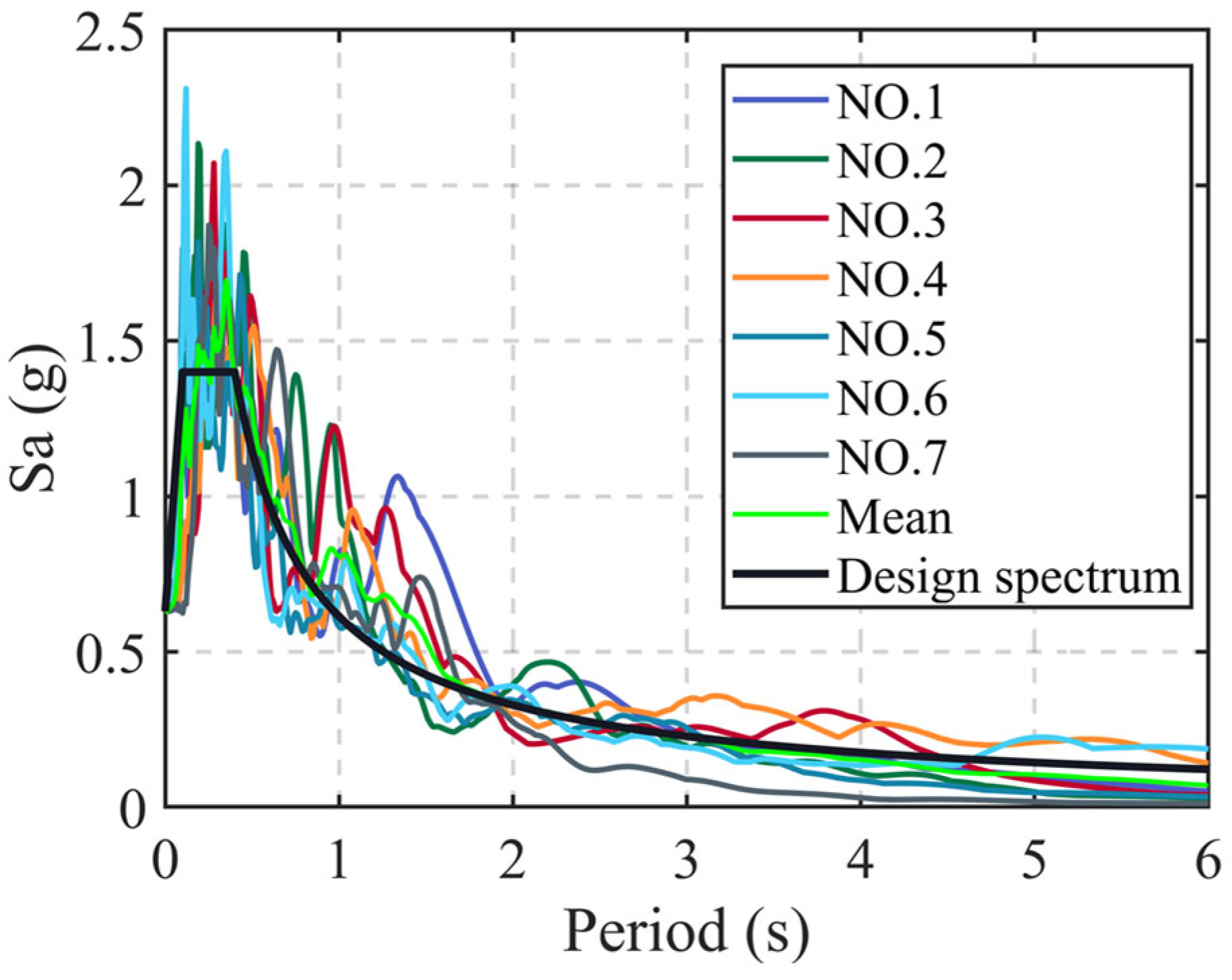
| Number | No. in PEER | Year | Mean Square Error | Station Name | Magnitude |
|---|---|---|---|---|---|
| NO. 1 | 392 | 1983 | 0.015 | Coalinga-14th and Elm (Old CHP) | 5.38 |
| NO. 2 | 1056 | 1994 | 0.018 | Phelan—Wilson Ranch | 6.69 |
| NO. 3 | 1297 | 1999 | 0.017 | HWA051 | 7.62 |
| NO. 4 | 1499 | 1999 | 0.014 | TCU060 | 7.62 |
| NO. 5 | 3160 | 1999 | 0.014 | TCU014 | 6.2 |
| NO. 6 | 6736 | 2004 | 0.015 | SIT011 | 6.63 |
| NO. 7 | 8855 | 2008 | 0.019 | Shoshone | 5.39 |
| Number | Maximum Isolator Displacement (m) | Maximum Rooftop Acceleration (m/s2) | ||||
|---|---|---|---|---|---|---|
| DTD | LRB | Improvement Rate (%) | DTD | LRB | Improvement Rate (%) | |
| NO. 1 | 0.174 | 0.235 | 25.97% | 6.343 | 8.321 | 23.77% |
| NO. 2 | 0.110 | 0.120 | 8.97% | 5.703 | 6.790 | 16.02% |
| NO. 3 | 0.169 | 0.178 | 5.09% | 6.248 | 8.718 | 28.34% |
| NO. 4 | 0.133 | 0.152 | 12.79% | 5.733 | 7.377 | 22.29% |
| NO. 5 | 0.106 | 0.117 | 10.08% | 5.880 | 6.254 | 5.98% |
| NO. 6 | 0.124 | 0.134 | 7.72% | 6.267 | 6.895 | 9.11% |
| NO. 7 | 0.117 | 0.135 | 13.13% | 6.049 | 8.589 | 29.57% |
Disclaimer/Publisher’s Note: The statements, opinions and data contained in all publications are solely those of the individual author(s) and contributor(s) and not of MDPI and/or the editor(s). MDPI and/or the editor(s) disclaim responsibility for any injury to people or property resulting from any ideas, methods, instructions or products referred to in the content. |
© 2023 by the authors. Licensee MDPI, Basel, Switzerland. This article is an open access article distributed under the terms and conditions of the Creative Commons Attribution (CC BY) license (https://creativecommons.org/licenses/by/4.0/).
Share and Cite
Sun, T.; Peng, L.; Li, X.; Guan, Y. Developing and Applying a Double Triangular Damping Device with Equivalent Negative Stiffness for Base-Isolated Buildings. Buildings 2023, 13, 3008. https://doi.org/10.3390/buildings13123008
Sun T, Peng L, Li X, Guan Y. Developing and Applying a Double Triangular Damping Device with Equivalent Negative Stiffness for Base-Isolated Buildings. Buildings. 2023; 13(12):3008. https://doi.org/10.3390/buildings13123008
Chicago/Turabian StyleSun, Tianwei, Lingyun Peng, Xiaojun Li, and Yaxi Guan. 2023. "Developing and Applying a Double Triangular Damping Device with Equivalent Negative Stiffness for Base-Isolated Buildings" Buildings 13, no. 12: 3008. https://doi.org/10.3390/buildings13123008
APA StyleSun, T., Peng, L., Li, X., & Guan, Y. (2023). Developing and Applying a Double Triangular Damping Device with Equivalent Negative Stiffness for Base-Isolated Buildings. Buildings, 13(12), 3008. https://doi.org/10.3390/buildings13123008