Article

Evaluation of Mechanical Properties, Corrosion Resistance, and Pore Structure of Stepwise PCM Aggregate Concrete

1
China Railway 20th Bureau Group Co., Ltd., Xi’an 710016, China
2
School of Civil Engineering, Xi’an University of Architecture and Technology, Xi’an 710055, China
*
Author to whom correspondence should be addressed.
Buildings 2023, 13(12), 3076; https://doi.org/10.3390/buildings13123076
Submission received: 11 November 2023 / Revised: 28 November 2023 / Accepted: 5 December 2023 / Published: 11 December 2023
(This article belongs to the Section Building Materials, and Repair & Renovation)

Abstract

:
Stepwise phase change material (PCM) aggregate concrete has advantages in controlling temperature and resisting frost heave, but its freeze–thaw resistance performance is still unclear. This paper explored the impact of replacing ordinary coarse aggregate with stepwise aggregate on the freeze–thaw resistance characteristics of concrete. Firstly, the compressive strength, splitting tensile strength, and their relationship were evaluated. Then, the freeze–thaw resistance properties of PCM aggregate concrete were investigated, including macroscopic changes, mass loss, relative dynamic elasticity modulus loss, and compressive strength loss. Subsequently, the pore changes before and after freeze–thaw cycles were tested through non-destructive testing and nuclear magnetic resonance (NMR) testing, and the evolution of pores under freeze–thaw cycles was explored. The results show that adding 100% PCM aggregate reduces the strength of concrete by 32%. However, due to the high porosity in the 100% PCM aggregate concrete, it would have an adverse impact on corrosion resistance. The corrosion resistance of concrete increases firstly and then decreases with the addition of PCM aggregate, which can be attributed to PCM aggregate having a limiting effect on pore development. Overall, a substitution rate of 60% is acceptable for compressive strength and corrosion resistance.

1. Introduction

Infrastructure in cold regions, such as high-speed railways and highways, is greatly affected by frost heave [1,2]. Temperature is one of the main causes of frost heave [3]. Stepwise phase change material (PCM) aggregate concrete can limit low temperatures, which can reduce frost heave amount and freezing depth [4]. Although stepwise PCM aggregate concrete has advantages in regulating thermal energy, its impact on freeze–thaw resistance is still unclear.
In cold regions, concrete structures are damaged due to freeze–thaw cycles, and freeze–thaw action is the primary factor in concrete deterioration, which directly affects the lifespan of concrete [5]. Concrete is a porous material with defects such as pores and cracks inside. When subjected to freeze–thaw cycles, the free water in the pores generates hydrostatic pressure, osmotic pressure, and crystallization pressure [6,7,8], which will lead to concrete failure. The infrastructure engineering in the cold regions of northern and southwestern China has been extensively affected by freeze–thaw damage [9]. Therefore, the study of freeze–thaw resistance strategies has a great significance for the application of concrete in cold regions.
Scholars from around the world have conducted extensive research on improving the freeze–thaw resistance of concrete, mainly focused on material modification. Adding mineral admixtures or fillers, such as fly ash, can improve frost resistance. The active effect and filling effect of fly ash particles contribute to improving the bonding ability of aggregates and slurries [10,11], and the internal pores are filled with fly ash particles [12]. This makes the internal structure of concrete dense, cuts off the seepage channels in the concrete, and improves the frost resistance of concrete. The research of Wang et al. [11] showed that the internal structure of concrete with 25% fly ash addition becomes denser after freeze–thaw cycles compared ordinary concrete, which is related to the filling of micropores and microcracks by fly ash generated products. Zhang et al. [13] studied the freeze–thaw resistance of fly ash as fine aggregate under stress and high temperature, and the results showed that fly ash fine aggregate concrete has higher freeze–thaw resistance than ordinary concrete. In addition to fly ash, other micro-particles can also improve the frost resistance of concrete, such as silica fume [14], metekaolin [15], rice husk ash [16], ground-granulated blast-furnace slag [17], and nanoparticles [18]. The reasons for improving freeze–thaw resistance of these materials can be summarized in two aspects: pozzolanic reaction and reduced permeability, which are beneficial for improving the internal defects of concrete and thus improving its freeze–thaw resistance. In addition, fiber addition can prevent crack propagation and improve freeze–thaw resistance. Cui et al. [19] showed that adding fibers significantly enhances all the wheel-impact indexes of airport pavement concrete under freeze–thaw conditions, which can be attributed to the fiber addition that limited crack expansion, inhibited seepage, and effectively reduced water transfer channels.
The freeze–thaw resistance also can be improved by the incorporation of air-entraining agents. The addition of air-entraining agents is conducive to generating a large number of microbubbles, which improve the pore structure of the concrete and reduce the maximum expansion pressure. When concrete was subjected to freeze–thaw cycles, water froze in the capillary pores of the cement matrix. Due to the formation of ice, the volume expanded and the squeezed water generated internal stress on the concrete, and bubbles could accommodate the squeezed water, which allowed stress to be released [20,21]. Therefore, air entrainment can provide expansion space for water, thereby improving the frost resistance of concrete.
In addition to being related to the material properties of concrete, the freeze–thaw characteristics are also related to environmental factors, such as freezing rate, minimum freezing temperature, and duration at minimum temperature [22]. The scaling damage was decreased by an increase in the freezing rate, and the effect of freezing rate on the scaling amount also depended on water-to-cement ratio [23]. The minimum temperature affected the phase transformation and migration of pore water, the low temperature led to accelerating pore water crystallization, and the generated temperature stress would accelerate concrete failure due to the heterogeneity of concrete [24]. The minimum temperature seemed to have a greater impact on scaling damage than the cooling rate, and the lower freezing temperatures caused greater expansion pressure that exacerbated the scaling damage [25]. A longer exposure time at the minimum temperature caused higher scaling damage and internal deterioration. Longer exposure time at the minimum temperature provided the time needed for the water to transport, resulting in increasing damage.
It seems that adjusting concrete internal temperature can improve freeze–thaw resistance characteristics. In recent years, PCM concrete has become a hot topic due to its ability to regulate temperature through latent heat. When temperature decreases, PCM releases latent heat, and when temperature rises, it absorbs latent heat, thereby achieving the purpose of temperature regulation. Currently, there are some studies on improving freeze–thaw properties of concrete by PCM. Yu et al. [26] chose expanded graphite (EG) as a carrier to encapsulate PCM and then incorporated it into concrete, and they found that mortar with 4% EG-PCM can increase the center temperature of concrete, which reduced the freeze–thaw damage of cement mortar. Tian et al. [27] developed artificial PCM aggregate, and their results showed that the PCM aggregates have high freeze–thaw resistance, with maximum strength reaching 66% of 28 d strength after 200 freeze–thaw cycles. Liu et al. [28] prepared cementitious materials integrated with PCM encapsulated by diatomite, showing that the incorporation of PCM weakened the mechanical properties of the cement matrix but improved the frost resistance. This can be explained by the following effect of PCM: when ambient temperature drops below the critical level, PCMs release latent heat, which guarantees the cement matrix at a relatively safe level.
However, freeze–thaw damage aggravates during continuous temperature decrease. The existing research focuses on the fact that that PCM stabilizes temperature by releasing latent heat within a single temperature point, once the temperature exceeds transition temperature, the PCM completes phase transition and cannot continue to release latent heat. Unfortunately, there is little research on regulating temperature at multiple phase transition points to resist freeze–thaw cycles. This paper focuses on developing the PCM concrete with continuous phase transition points during temperature decreases. Utilizing the latent heat released during the temperature drop process helps to resist the adverse effects of freeze–thaw.
This paper aims to study the mechanical properties and freeze–thaw resistance of concrete incorporated with stepwise PCM aggregates, whose transition temperature is from 5 to −15 °C. Firstly, the mechanical properties of concrete, whose coarse aggregate was replaced by 0–100% stepwise PCM aggregate, were evaluated, including cubic compressive strength and cubic splitting tensile strength. Secondly, the freeze–thaw resistances of concrete with different replacement amounts of stepwise PCM aggregates were evaluated from macroscopic changes, quality loss, relative dynamic elasticity modulus (RDEM) loss, and compressive strength loss. Finally, non-destructive nuclear magnetic resonance (NMR) technology was used to detect the changes in internal pores of concrete after freeze–thaw cycles. This paper will further expand the research on the freeze–thaw resistance of concrete using PCM.

2. Materials and Experimental Details

2.1. Materials

The cementitious material was ordinary Portland cement, with a strength grade of 42.5R, produced from Shaanxi, China. Natural gravel and river sand were produced in Shaanxi, China. The particle size range of gravel was 5–20 mm, the modulus of river sand was 2.69. In this study, shale ceramsite was used to encapsulate PCM, and the particle size range of ceramsite was 5–20 mm. Shale ceramsite had abundant internal pores, which can be used for a container of PCM. The porosity of ceramsite was 33.30%. The micro-morphology of ceramic particles is shown in Figure 1. The main physical properties of shale ceramsite were obtained by testing and are shown in Table 1.
Three PCMs, dodecane, tridecane and tetradecane, were used to prepare stepwise PCM aggregate, including dodecane aggregate, tridecane aggregate and tetradecane aggregate. The thermal properties of three PCMs were tested using a differential scanning calorimeter and are shown in Table 2. Epoxy resin was used as the first coating layer, and cement powder was used as the second coating layer.

2.2. Preparation of PCM Aggregate and Stepwise PCM Aggregate Concrete

2.2.1. PCM Aggregate Prepared by Vacuum Impregnation

In this paper, dodecane aggregate, tridecane aggregate, and tetradecane aggregate were prepared using vacuum impregnation method, and their combination had stepwise phase transition temperature points. Firstly, the shale ceramsite particles were cleaned and then dried in an oven for 24 h. Subsequently, PCM and shale ceramsite particles were mixed and placed in a vacuum heating box, the temperature was set to 60 °C, and the particles were vacuumed for 60 min and then placed in the box for another 60 min. After the above measures, vacuum impregnation process was completed.

2.2.2. PCM Aggregate Coated by Double-Layer Material

PCMs adsorbed with porous aggregates were prone to leakage during the phase change process, the leaked PCM hindered the cement hydration process [29,30]. Suitable coating material to coat PCM aggregate had a better compatibility, such as cement paste [31]. In order to prevent the adverse effects of PCM on the cement matrix, this paper uses epoxy resin and cement powder as coating materials, and the specific ratio is discussed in this paper [4]. PCM aggregate was firstly wrapped by epoxy resin, and after 4 h, when epoxy resin had not yet lost its adhesion, the PCM aggregate was wrapped by cement powder. After being wrapped by the first layer, PCM aggregate was left for 8 h for the first-layer epoxy resin to solidify and finally placed in water for second-layer cement to hydrate. After 3 days, coated PCM aggregate was taken out for subsequent use. The schematic diagram of PCM aggregates for each stage is shown in Figure 2. Due to the density of PCM in this paper being close, the quality of each component for PCM aggregate is also very close. The proportion of each component and the latent heat of PCM aggregate are shown in Table 3 and Table 4.

2.2.3. Stepwise PCM Aggregate Concrete

According to previous research, dodecane aggregate, tridecane aggregate and tetradecane aggregate were mixed in a ratio of 4:3:3 and incorporated into concrete to prepare stepwise PCM aggregate concrete, which has stepwise phase transition temperature points between 5 and −15 °C. In this paper, the three types of PCM aggregates replaced coarse aggregates at 0% to 100% by volume substitution. The mix proportion of stepwise PCM aggregate concrete is shown in Table 5. The control mixture was cast without any PCM aggregate. In the next five mixtures, 20%, 40%, 60%, 80%, and 100% of coarse aggregates were replaced by stepwise PCM aggregate. The water–cement ratio was fixed at 0.32, the sand-gravel ratio was 37.60%.
In order to prevent PCM aggregate from crushing during the mix process, the preparation process has been adjusted according to the reference [4] and is presented as follows:
(1)
Cement and sand were mixed together and stirred for 60 s.
(2)
Then, water and superplasticizer were added and stirred for 120 s.
(3)
Subsequently, the stepwise PCM aggregates were added and stirred for 120 s.
(4)
Finally, the mixture was poured into molds and vibrated to compact.
The specimen was demolded after 1 d, then cured in curing room with a humidity of 96% and a temperature of 20 °C for 28 d. Cubic specimens, with a size of 100 mm × 100 mm × 100 mm, were used to test mechanical properties and also used for nondestructive testing. Prismatic specimens, with a size of 100 mm × 100 mm × 400 mm, were used to test freeze–thaw resistance.

2.3. Experimental Techniques

2.3.1. Mechanical Properties

A 2000 KN microcomputer-controlled electro-hydraulic servo universal testing machine was used to test compressive strength and splitting tensile strength. The 7, 14 and 28 d strengths were tested, and each group ensured at least three specimens for improving the test data accuracy.

2.3.2. Freeze–Thaw Resistance

Freeze–thaw cycle test was conducted in a concrete automatic quick freeze–thaw machine. The test method was in accordance with ordinary concrete durability and long-term performance test methods (Chinese standard GB/T 50082-2009 [32]). The freeze–thaw resistance was tested by rapid freeze–thaw for 0, 50, 100, 150, 200 cycles. In each cycle, the maximum temperature was 5 °C and minimum temperature was −18 °C. The mass, relative dynamic elasticity modulus (RDEM) and strength were tested after freeze–thaw cycles to characterize the freeze–thaw resistance. The average value of three specimens was used as the final result in the test to ensure the accuracy of test data.
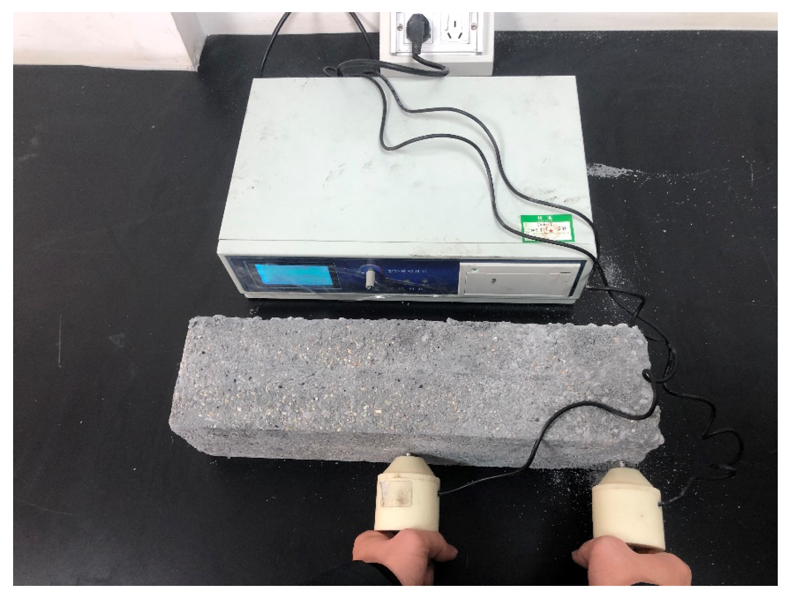
Concrete specimen weight was measured by an electronic scale, and the surface water was wiped dry before weighting. The mass loss rate was measured after prescribed freeze–thaw cycles using Equation (1). A resonator was used to test RDEM. The experiment used the prism with a size of 100 mm × 100 mm × 400 mm. The water on the specimen surface was wiped. In order to ensure full contact between the measuring rod and the specimen, vaseline was applied as a medium on the contact surface between the measuring rod and specimen. There were two measuring rods, one was the transmitting unit and the other was the receiving unit. The transmitting unit was attached at the middle of the specimen, and the receiving unit was 5 mm away from the edge of the specimen, as shown in Figure 3. The RDEM loss rate was calculated using Equation (2). The cubic compressive strength, fcu, was tested using a compression testing machine. The fcu loss rate was calculated using Equation (3).
Δ m n = m 0 m n m 0
where Δmn is the mass loss rate after n time freeze–thaw cycles, m0 is the initial mass, and mn is the mass after n time freeze–thaw cycles.
Δ E d = E d 0 E d n E d 0
where ΔEd is the RDEM loss rate after n time freeze–thaw cycles, Ed0 is the initial RDEM, and Edn is the RDEM after n time freeze–thaw cycles.
Δ f c u = f c u 0 f c u n f c u 0
where Δfcu is the cubic compressive strength loss rate after n time freeze–thaw cycles, fcu0 is the initial compressive strength, and fcun is the compressive strength after n time freeze–thaw cycles.

2.3.3. NMR Test

Nuclear magnetic resonance (NMR) is a non-destructive testing method and is widely used in the field of detecting concrete pores. The measurement of relaxation time in cementitious materials can be divided into longitudinal relaxation time and transverse relaxation time. It is difficult to measure the longitudinal relaxation time and establish a relationship with pores, so measuring the transverse relaxation time is adopted. Before testing, the concrete specimens were fully saturated with water. By using the NMR method, the transverse relaxation rate (1/T2) of hydrogen atom spin in concrete specimens was measured. Based on the fast exchange assumption, the relationship between the transverse relaxation and pore distribution was obtained [33], as shown in Equation (4).
1 T 2 = ρ 2 , s u r ( S V )
where T2 is the transverse relaxation time, ρ2,sur is the T2 surface relaxivity, which is related to the properties of material itself, and S/V is the pore surface area-volume ratio.

3. Results and Discussion

3.1. Mechanical Properties

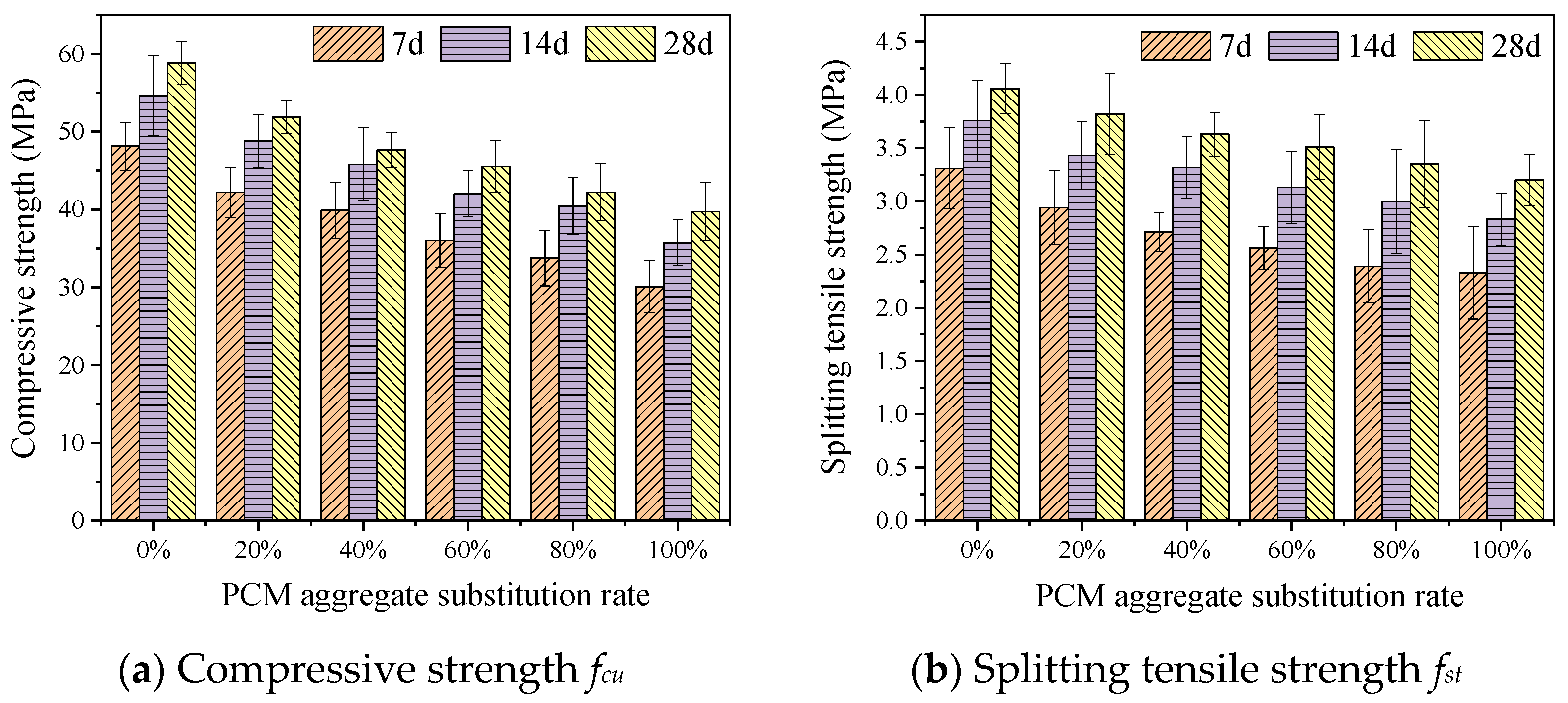
Figure 4a,b shows the 7, 14, and 28 d cubic compressive strength and splitting tensile strength of concrete after incorporating different proportions of PCM aggregates. Figure 5 shows the relationship between compressive strength and splitting tensile strength.
As shown in Figure 4a, the compressive strength fcu increased with curing age increase. At curing for 28 d, the fcu of concrete without the incorporation of PCM aggregate reached 58.84 MPa, and the fcu of the concrete with a curing age of 7 and 14 d reached 81.83% and 92.86% of the 28 d fcu, respectively. In addition, the fcu gradually decreased with the increase in PCM aggregate substitution rate. The fcu of the concrete-integrated 20–100% PCM aggregate decreased by 11.88% to 32.46%. This is due to the difference in strength between the aggregates. The strength of natural aggregate is higher than that of PCM aggregate, resulting in a reduction in strength with the replacement of PCM aggregate. This conclusion is identical that found in the literature [34,35]. The 28 d strength of concrete replaced by 60% PCM aggregate was 45.55 MPa, and the 7 and 14 d strengths were 79.07% and 92.23% of the 28 d strength, respectively. The 28 d strength of concrete replaced by 100% PCM aggregate was 39.74 MPa, and the 7 and 14 d strengths were 75.69% and 89.93% of the 28 d strength, respectively. With the substitution rate increased, the proportion of 7 and 14 d strengths to 28 d strength decreased, which was due to the unfavorable impact on strength caused by the incomplete solidification of the PCM aggregate wrapping layer in the early stage.
As shown in Figure 4b, the splitting tensile strength fst also increased with curing age. After curing for 28 d, the maximum strength was 4.06 MPa, and the 7 and 14 d strengths were 81.53% and 92.61% of the 28 d strength, respectively. With the substitution rate of PCM aggregate increased, fst also showed the same trend as compressive strength. After the coarse aggregate was completely replaced by PCM aggregate, the fst decreased by 21.18%.
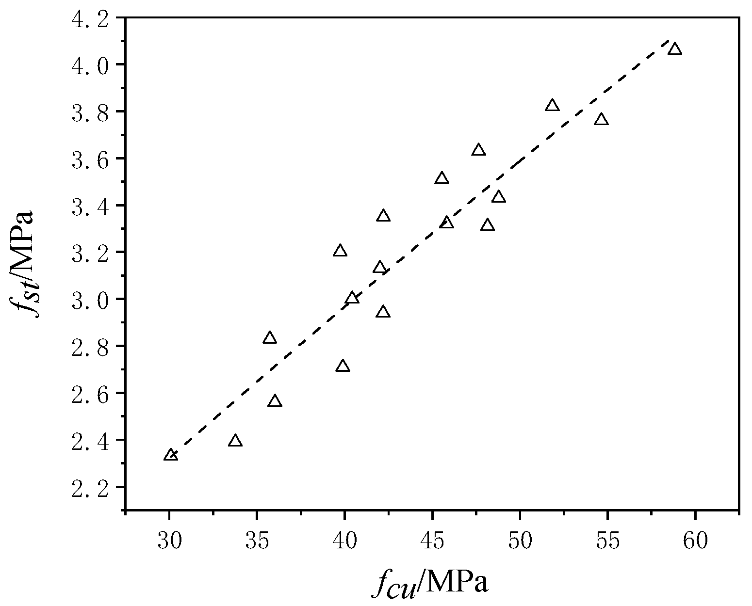
The relationship between fcu and fst was given in Figure 5. The relationship between the two equations can be expressed as Equation (5).
f s t = a · f c u b
In this paper, fitting and analyzing the test data by using origin software, the fcu-fst fitting curve, fitting equation (Equation (6)), and correlation coefficient R2 were obtained. The correlation coefficient R2 = 0.89, with high fitting accuracy.
f s t = 0.128 × f c u 0.85
The relationship between fcu and fst advised by American Concrete Institute (ACI), Concrete European Board (CEB), and Australia (AS), respectively, were listed from Equation (7) to Equation (9).
f s t = 0.59 × f c u 0.5
f s t = 0.301 × f c u 0.67
f s t = 0.4 × f c u 0.5
The fitting equation, Equation (6), was compared with the equations recommended by various countries, as shown in Figure 6. The value of the fitting equation was lower than the equation recommended by the United States and Europe but higher than the equation recommended by Australia. In order to further clarify the numerical differences, the differences of the fitted fst of concrete under different substitution amounts of PCM aggregates and the fst recommended by various countries were calculated, as shown in Table 6. It was worth noting that with the replacement amount of PCM aggregate increased, the difference between the recommended values in the United States and Europe increased, while the difference between the recommended values in Australia decreased.

3.2. Freeze–Thaw Resistance

3.2.1. Morphology

The morphologies of the concrete prisms after 50, 100, 150, 200 freeze–thaw cycles are presented in Figure 7. The number of freeze–thaw cycles gradually increases from top to bottom in the figure. As the freeze–thaw cycles increased, the surface morphology gradually deteriorated, but the severity was different. The surface damage of the ordinary concrete group and the 100% PCM aggregate concrete group was significant, compared with that of the other PCM aggregate concrete group. In the ordinary concrete group, several cracks appeared on the surface after 150 freeze–thaw cycles. Subsequently, the cracks continued to expand. After 200 freeze–thaw cycles, the surface cracks of ordinary concrete were large, and local scaling was severe. The freeze–thaw damage of the 100% PCM aggregate concrete group was also significant. Within 100 freeze–thaw cycles, the damage was relatively small, but after 150 cycles, the surface scaling was increased. At 200 cycles, the surface scaling became more severe, and the through crack appeared in the middle of the sample. However, there was less damage after freeze–thaw cycles in 20% and 60% PCM aggregate concrete, especially in the 60% substitution group. This is due to the addition of PCM aggregate. However, the high substitution has an adverse effect on the concrete system.

3.2.2. Mass Loss

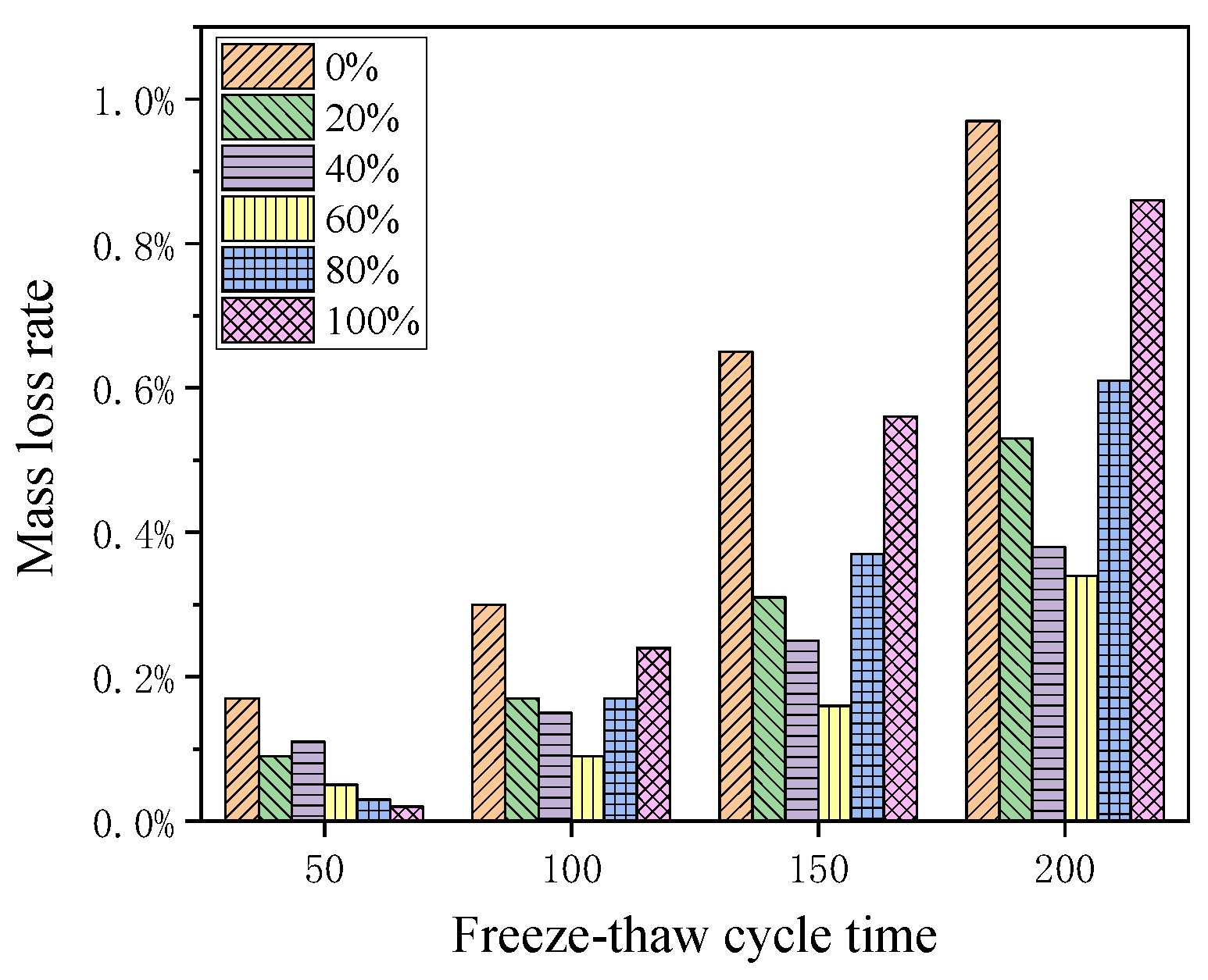
The mass loss rates of ordinary concrete and PCM aggregate concrete after freeze–thaw cycles are shown in Figure 8. The replacement of PCM aggregates can reduce mass loss to a certain extent. At 50 cycles, the mass loss rate gradually decreased with the replacement of PCM aggregates, and the more PCM aggregates were added, the smaller the mass loss. After 100 freeze–thaw cycles, the mass loss of high substitute rate PCM aggregate concrete began to increase. After 150 to 200 cycles, the mass loss of ordinary concrete and high substitution rate PCM aggregate concrete increased significantly, but the mass loss of other substitution rate PCM aggregate concrete, especially the 60% substitution rate, was still relatively small compared to ordinary concrete. In the early stage of freeze–thaw, an increase in PCM aggregate content is beneficial for reducing mass loss. However, as the time of freeze–thaw cycles increases, the mass loss of high substitute rate PCM aggregate concrete increases rapidly. After 200 cycles, the mass loss of 60% PCM aggregate concrete is the least.
The damage of freeze–thaw is not severe in the early stage, and the addition of PCM aggregate is beneficial for improving the frost resistance of concrete. However, as the freeze–thaw damage intensifies, the advantageous impact of PCM aggregate on frost resistance is not enough to offset the adverse effects of PCM aggregate. Therefore, the frost resistance of 100% PCM aggregate concrete decreases after 50 freeze–thaw cycles. However, the beneficial effect of PCM aggregates on concrete is greater than the adverse effect in 60% PCM aggregate concrete, exhibiting the best frost resistance performance.

3.2.3. RDEM Loss

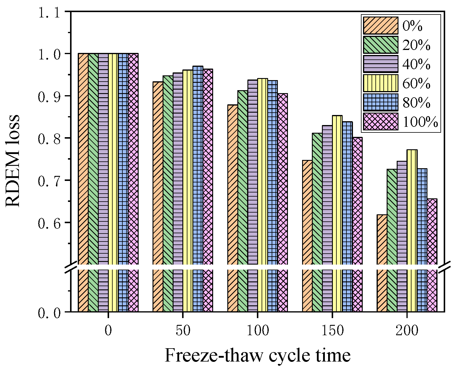
The RDEM losses of concrete under different substitution amounts of PCM aggregate concrete are shown in Figure 9. As the number of freeze–thaw cycles increased, the RDEM loss increased. Within 50 cycles, the differences between different groups were relatively small. After 100 freeze–thaw cycles, the differences gradually increased—namely, the loss of the ordinary concrete group began to increase. After 100 freeze–thaw cycles, the RDEM of ordinary concrete decreased to 88%, and after 200 cycles, the RDEM was only 62%, indicating significant damage in ordinary concrete. The RDEM loss of concrete incorporated with PCM aggregate was smaller than that of ordinary concrete, which is attributed to the temperature control effect of PCM aggregate on concrete, reducing the amplitude of temperature change. The results indicate that PCM aggregate can slow down the internal damage of concrete. In the early stages of freeze–thaw cycles, an increase in the replacement rate of PCM aggregate could improve the RDEM loss. However, when the freeze–thaw cycle reached 100 cycles, the RDEM loss of high replacement rate PCM concrete accelerated. After 100 freeze–thaw cycles, the RDEM of 100% PCM aggregate concrete decreased to 90%, and after 200 cycles, it decreased to 66%. When the substitution rate was 60%, the RDEM was the highest among all PCM aggregate concrete, indicating the best frost resistance. The experimental results indicate that when the substitution rate exceeds 60%, continuing to add PCM aggregates cannot improve the frost resistance, which also confirms the result of mass loss rate.

3.2.4. Strength Loss

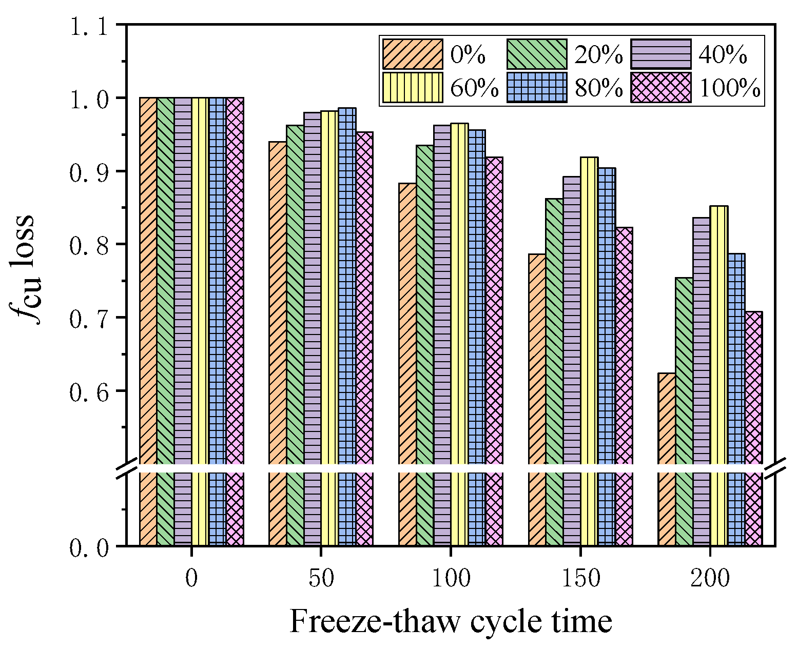
The strength loss of different concrete groups under freeze–thaw environment is shown in Figure 10. As the number of freeze–thaw cycles increased, the strength loss gradually increased. However, PCM aggregates could reduce the loss of mechanical properties to a certain extent. Ordinary concrete experienced significant strength loss after freeze–thaw cycles, the strength decreased to 88% after 100 cycles, and then the loss accelerated. By 200 cycles, the strength was only 62%, and the strength loss exceeded 25%. Compared to ordinary concrete, PCM aggregate concrete showed higher strength, indicating that the addition of PCM aggregate can improve the frost resistance of concrete. In the early stage of freeze–thaw environment, the addition of PCM aggregates seemed to have a positive effect on improving strength. After more than 100 freeze–thaw cycles, the gap between different PCM aggregate concrete groups gradually increased. When the replacement amount of PCM aggregate was 60%, it showed the minimum strength loss and can still maintain 85% strength after 200 cycles. However, further increase in substitution rate seemed to have a negative impact on the freeze–thaw resistance. The strength loss of 100% PCM aggregate concrete was 8% and 29%, respectively, after 100 and 200 freeze–thaw cycles, but the strength loss was still smaller than that of ordinary concrete.

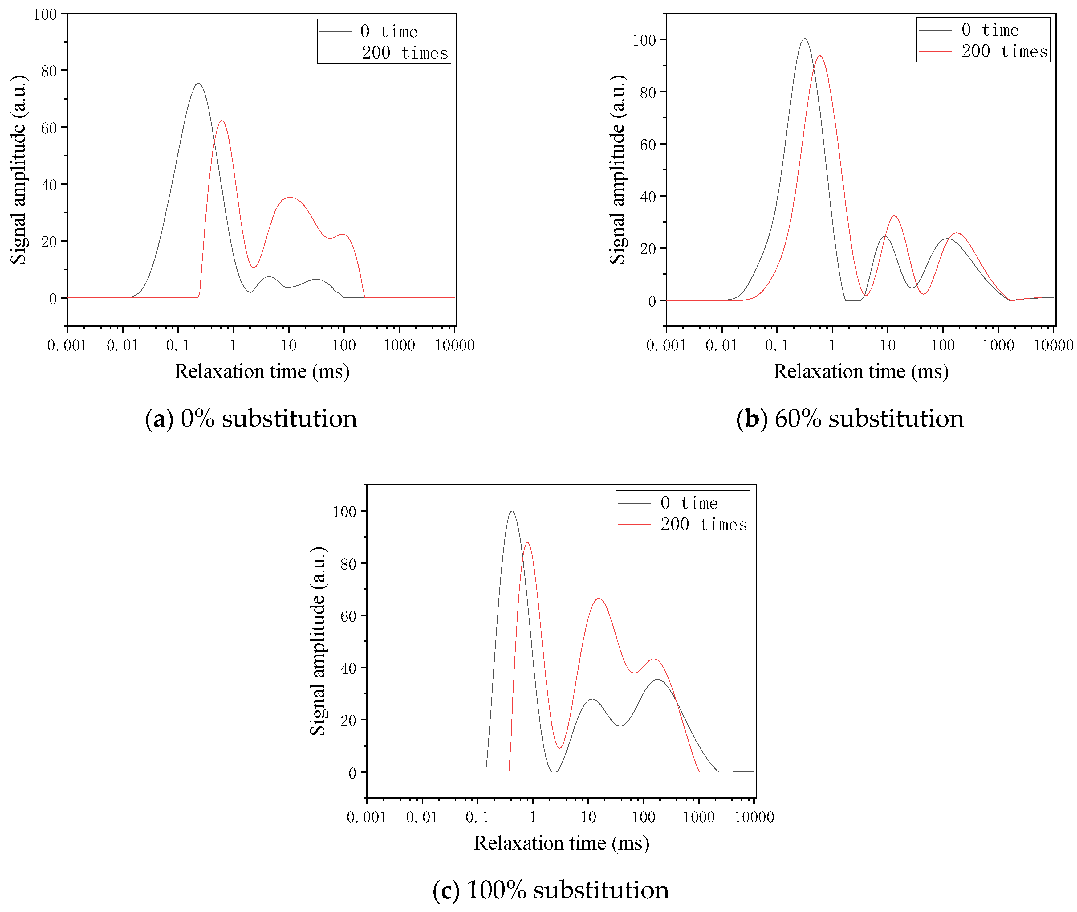
3.3. Pore Evaluation by NMR

The T2 spectra of different concretes detected by nuclear magnetic resonance are shown in Figure 11. The abscissa represents the relaxation time and is related to the pore size. The vertical axis represents the signal intensity, and its area is related to porosity. Each T2 spectrum consists of three peaks, which can be considered as micropores, mesopores, and macropores from left to right based on the pore size. After the freeze–thaw cycles, it can be seen that the area of micropore peaks decreases, while the area of mesopore peaks and macropore peaks increases. It can be concluded that under the freeze–thaw cycle effect, the pores are subjected to internal stress, and micropores gradually develop into larger pores. It is worth noting that the highest intensity point of peak shifts to the right in various degrees, indicating an increasing trend in pore size. After freeze–thaw cycles, the damage of each group of concrete were different. After 200 freeze–thaw cycles, the area of mesoporous and macroporous peaks in ordinary concrete increased significantly, as shown in Figure 11a, indicating that the internal damage of ordinary concrete was severe, mainly due to the action of mesopores and macropores causing damage to the concrete. The three highest intensity points of ordinary concrete showed a significant shift to the right, indicating a significant change in pore size under freeze–thaw cycles. The mesoporous peak and macroporous peak of 100% PCM aggregate concrete also showed a significant increase, and it was worth noting that high content PCM aggregate had a larger pore volume inside before freeze–thaw, as shown in Figure 11c, indicating that higher pores may have adverse effects on freeze–thaw resistance. This is because the favorable temperature control effect of PCM aggregate cannot change the negative impact of high pore volume. The concrete with a 60% PCM aggregate content exhibited high frost resistance after freeze–thaw cycles. As shown in Figure 11b, although both the mesoporous and macroporous peaks increased after freeze–thaw cycles, their growth was relatively gentle compared to ordinary concrete and 100% PCM aggregate concrete. The experimental results indicate that PCM aggregate has outstanding performance in alleviating freeze–thaw damage.
In order to provide a more intuitive explanation of the changes in pore volume, the T2 spectrum areas of each pore after freeze–thaw cycles are displayed, as shown in Figure 12. The intensity integral area is directly related to the pore volume. After freeze–thaw cycles, the volume of micropores in ordinary concrete and 100% PCM aggregate concrete decreased significantly, while the volume of mesopores increased significantly. This indicates that more micropores develop into mesopores under the action of internal stress after freeze–thaw cycles, leading to severe damage inside the concrete. However, in concrete mixed with 60% PCM aggregate, although the micropore volume decreased after freeze–thaw, the increase in mesopore volume was relatively small, and there was no excessive increase, as was the case in ordinary concrete and 100% PCM aggregate concrete. This indicates that concrete incorporated with 60% PCM aggregate exhibits good frost resistance.
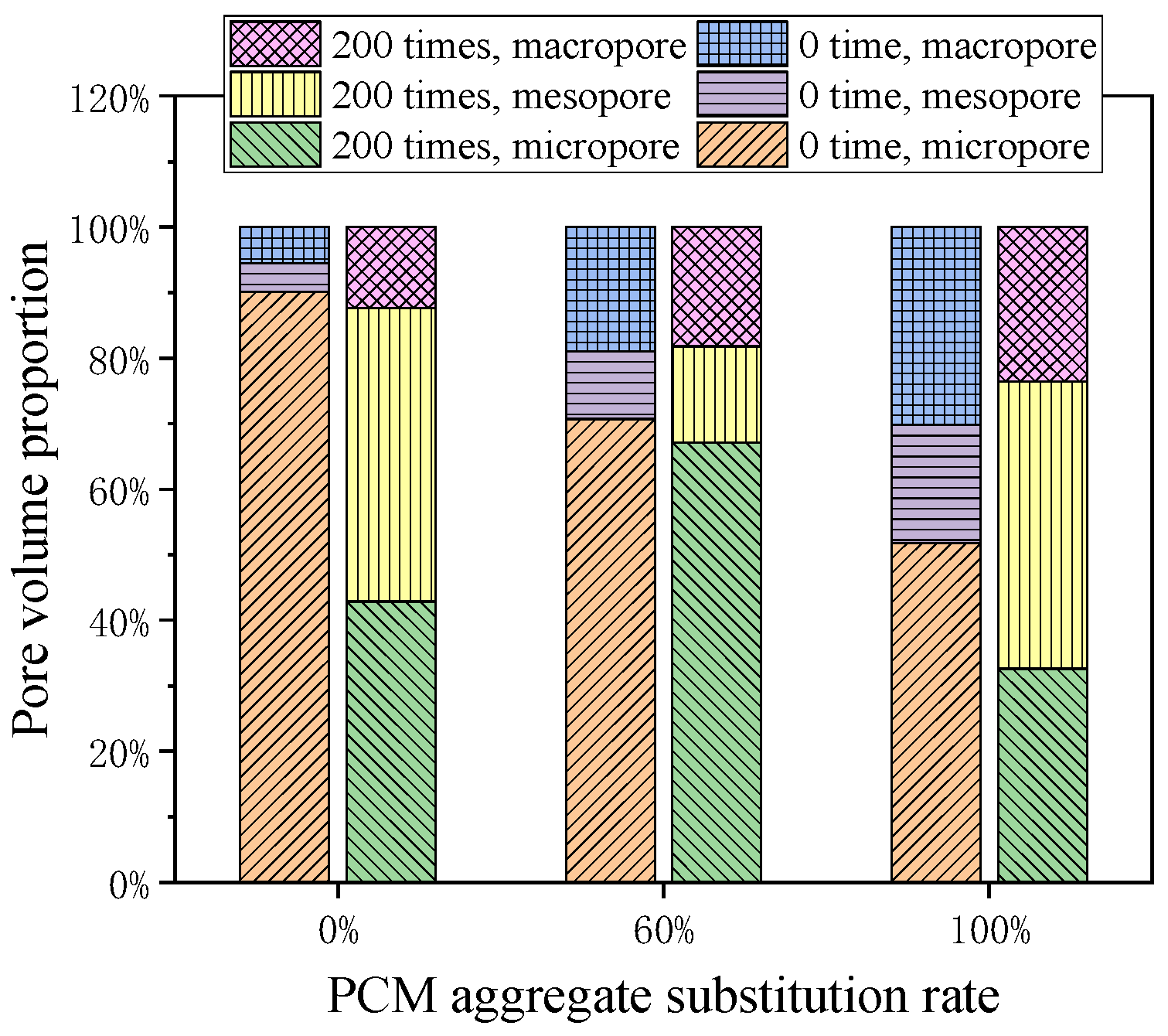
The volume ratios of micropores, mesopores, and macropores before and after freeze–thaw cycles are presented in Figure 13. The majority of micropores were found in ordinary concrete, but after freeze–thaw cycles, the volume ratio of micropores was 42.85%, and the volume ratio of mesopores was 44.74%. After freeze–thaw cycles, the volume of micropores decreased by 52%, but the volume of mesopores increased by nearly 10 times. The severe increase in the volume of mesopores was the main reason for concrete deterioration after freeze–thaw cycles. Similarly, after freeze–thaw testing, the micropore volume of 100% PCM aggregate concrete with poor frost resistance decreased by 37%, while the mesopore volume increased to 2.42 times. However, the micropore volume of 60% aggregate concrete decreased by 5%, while the mesopore volume only increased by 1.42 times after freeze–thaw cycles, demonstrating the excellent performance of PCM aggregate in freeze–thaw resistance. Before the freeze–thaw cycle, the proportion of micropores in each group was the highest. However, after freeze–thaw cycles, the proportion of mesopores in ordinary concrete and 100% PCM aggregate concrete was the highest, while the proportion of micropores in 60% PCM aggregate concrete was still the highest. This indicates that PCM aggregate substitution at 60% can have the best frost resistance performance.
PCM aggregates are beneficial for freeze–thaw resistance, but the pores of concrete also continue to increase with the increase in PCM aggregates, which will have adverse effects on frost resistance. The beneficial effect of PCM aggregate is greater than the adverse effect in 60% PCM aggregate concrete, demonstrating the best frost resistance performance. However, the adverse effects of high porosity cannot be offset in 100% PCM aggregate concrete, resulting in a decrease in frost resistance.

4. Conclusions

This paper develops stepwise PCM aggregate concrete and evaluates its mechanical properties and freeze–thaw resistance. Due to the excellent temperature control ability of PCM aggregates, it is possible to improve frost resistance by incorporating PCM aggregates into concrete. Therefore, this paper studies the compressive strength, and the splitting tensile strength of concrete replaced coarse aggregate by 0% to 100% stepwise PCM aggregate. Subsequently, 200 freeze–thaw cycles are conducted on prisms and cubic specimens to evaluate the macroscopic morphology, mass loss, dynamic modulus loss, and strength loss after freeze–thaw cycles. Finally, the changes in pore volume are explored through microscopic NMR techniques. The main conclusions are as follows:
After adding PCM aggregate, the compressive strength and splitting tensile strength of concrete decrease, but even with the addition of 100% PCM aggregate, its strength is still higher than 30 MPa, which is acceptable.
Subsequently, freeze–thaw tests are conducted. In the early stages of freeze–thaw cycles, the more PCM aggregates added, the better the frost resistance of the concrete. However, after more than 50 cycles, the high replacement rate PCM aggregate concrete rapidly deteriorates, but all indicators are still better than ordinary concrete. After 200 freeze–thaw cycles of ordinary concrete, the mass loss rate, RDEM, and strength all decreased significantly, but 60% PCM aggregate concrete shows good frost resistance.
Through NMR testing, it is found that the proportion of micropores in each group of concrete before freeze–thaw is relatively large, but the proportions of mesopores in ordinary concrete and 100% PCM aggregate concrete with severe deterioration after freeze–thaw cycles are the highest. This indicates that during the freeze–thaw process, micropores gradually develop into mesopores due to internal stress, ultimately causing damage to the concrete. However, the pore ratio of 60% PCM aggregate concrete remains relatively stable after freeze–thaw cycles, indicating that the concrete can have good freeze–thaw resistance when the substitution rate is 60%.
Stepwise PCM aggregate concrete exhibits the better freeze–thaw resistance compared to ordinary concrete, which can be attributed to the addition of PCM aggregate. The cost of PCM aggregate concrete is higher than that of ordinary concrete due to the expensive PCM. However, the PCM concrete can effectively resist the influence of freeze–thaw, which is very beneficial for improving the frost resistance of buildings in cold regions.

Author Contributions

Conceptualization, B.L. and S.W.; Data curation, W.J.; Formal analysis, B.L. and W.J.; Funding acquisition, B.L.; Investigation, J.X. and W.Z.; Methodology, B.L.; Project administration, B.L.; Resources, W.J.; Software, H.Y. and Z.L.; Supervision, S.W.; Validation, Z.L.; Visualization, H.Y.; Writing—original draft, B.L.; Writing—review and editing, B.L. All authors have read and agreed to the published version of the manuscript.

Funding

This work was supported by China Postdoctoral Science Foundation (No. 2022M723683), Key Research and Development Program of Shaanxi, China (No. 2022SF-375), Research Project of China Railway 20th Bureau Group Co., Ltd. (No. YF2200LJ12B) and Shaanxi Key Laboratory of Safety and Durability of Concrete Structures Open Fund project (No. SZ02307).

Data Availability Statement

The data presented in this study are available on request from the corresponding author. The data are not publicly available due to the requirements of projects.

Conflicts of Interest

Bo Liu, Wurong Jia, Jiangsheng Xie Weiling Zhong and were employed by the company China Railway 20th Bureau Group Co., Ltd. The remaining authors declare that the research was conducted in the absence of any commercial or financial relationships that could be construed as a potential conflict of interest.

References

  1. Tan, Z.; Gou, H.; Li, W.; Bao, Y. Effect of frost heave deformation of bridge foundation on operation safety of high-speed railway. Structures 2023, 47, 2099–2112. [Google Scholar] [CrossRef]
  2. Yu, F.; Qi, J.; Lai, Y.; Sivasithamparam, N.; Yao, X.; Zhang, M.; Liu, Y.; Wu, G. Typical embankment settlement/heave patterns of the Qinghai–Tibet highway in permafrost regions: Formation and evolution. Eng. Geol. 2016, 214, 147–156. [Google Scholar] [CrossRef]
  3. Niu, F.J.; Li, A.Y.; Luo, J.; Lin, Z.J.; Yin, G.A.; Liu, M.H.; Zheng, H.; Liu, H. Soil moisture, ground temperatures, and deformation of a high-speed railway embankment in Northeast China. Cold Reg. Sci. Technol. 2017, 133, 7–14. [Google Scholar] [CrossRef]
  4. Ying, H.; Wang, S.; Lu, Z.; Liu, B.; Cui, L.; Quan, X.; Liu, K.; Zhao, N. Development and thermal response of concrete incorporated with multi-stage phase change materials-aggregates for application in seasonally frozen regions. J. Build. Eng. 2023, 71, 106562. [Google Scholar] [CrossRef]
  5. Fu, Y.; Cai, L.; Yonggen, W. Freeze–thaw cycle test and damage mechanics models of alkali-activated slag concrete. Constr. Build. Mater. 2011, 25, 3144–3148. [Google Scholar] [CrossRef]
  6. Ma, H.; Yu, H.; Li, C.; Tan, Y.; Cao, W.; Da, B. Freeze–thaw damage to high-performance concrete with synthetic fibre and fly ash due to ethylene glycol deicer. Constr. Build. Mater. 2018, 187, 197–204. [Google Scholar] [CrossRef]
  7. Scherer, G.W. Crystallization in pores. Cem. Concr. Res. 1999, 29, 1347–1358. [Google Scholar] [CrossRef]
  8. Luo, S.; Bai, T.W.; Guo, M.Q.; Wei, Y.; Ma, W.B. Impact of Freeze-Thaw Cycles on the Long-Term Performance of Concrete Pavement and Related Improvement Measures: A Review. Materials 2022, 15, 4568. [Google Scholar] [CrossRef]
  9. Feng, D.; Yi, J.; Wang, D.; Chen, L. Impact of salt and freeze–thaw cycles on performance of asphalt mixtures in coastal frozen region of China. Cold Reg. Sci. Technol. 2010, 62, 34–41. [Google Scholar] [CrossRef]
  10. Wang, A.; Zhang, C.; Sun, W. Fly ash effects: II. The active effect of fly ash. Cem. Concr. Res. 2004, 34, 2057–2060. [Google Scholar] [CrossRef]
  11. Wang, D.; Zhou, X.; Meng, Y.; Chen, Z. Durability of concrete containing fly ash and silica fume against combined freezing-thawing and sulfate attack. Constr. Build. Mater. 2017, 147, 398–406. [Google Scholar] [CrossRef]
  12. Zheng, D.-D.; Ji, T.; Wang, C.-Q.; Sun, C.-J.; Lin, X.-J.; Hossain, K.M.A. Effect of the combination of fly ash and silica fume on water resistance of Magnesium–Potassium Phosphate Cement. Constr. Build. Mater. 2016, 106, 415–421. [Google Scholar] [CrossRef]
  13. Zhang, D.; Mao, M.; Zhang, S.; Yang, Q. Influence of stress damage and high temperature on the freeze–thaw resistance of concrete with fly ash as fine aggregate. Constr. Build. Mater. 2019, 229, 116845. [Google Scholar] [CrossRef]
  14. Sasanipour, H.; Aslani, F.; Taherinezhad, J. Effect of silica fume on durability of self-compacting concrete made with waste recycled concrete aggregates. Constr. Build. Mater. 2019, 227, 116598. [Google Scholar] [CrossRef]
  15. Kim, H.-S.; Lee, S.-H.; Moon, H.-Y. Strength properties and durability aspects of high strength concrete using Korean metakaolin. Constr. Build. Mater. 2007, 21, 1229–1237. [Google Scholar] [CrossRef]
  16. Chatveera, B.; Lertwattanaruk, P. Evaluation of sulfate resistance of cement mortars containing black rice husk ash. J. Environ. Manag. 2009, 90, 1435–1441. [Google Scholar] [CrossRef] [PubMed]
  17. Duan, P.; Shui, Z.; Chen, W.; Shen, C. Enhancing microstructure and durability of concrete from ground granulated blast furnace slag and metakaolin as cement replacement materials. J. Mater. Res. Technol. 2013, 2, 52–59. [Google Scholar] [CrossRef]
  18. Behfarnia, K.; Salemi, N. The effects of nano-silica and nano-alumina on frost resistance of normal concrete. Constr. Build. Mater. 2013, 48, 580–584. [Google Scholar] [CrossRef]
  19. Cui, Y.; Chen, Y.; Cen, G.; Peng, G. Comparative Study on the Effect of Organic and Inorganic Fiber on the Anti-wheel Impact Performance of Airport Pavement Concrete under Freeze-thaw Environment. Constr. Build. Mater. 2019, 211, 284–297. [Google Scholar] [CrossRef]
  20. Mayercsik, N.P.; Vandamme, M.; Kurtis, K.E. Assessing the efficiency of entrained air voids for freeze-thaw durability through modeling. Cem. Concr. Res. 2016, 88, 43–59. [Google Scholar] [CrossRef]
  21. Mousavi, S.S.; Guizani, L.; Bhojaraju, C.; Ouellet-Plamondon, C. The effect of air-entraining admixture and superabsorbent polymer on bond behaviour of steel rebar in pre-cracked and self-healed concrete. Constr. Build. Mater. 2021, 281, 122568. [Google Scholar] [CrossRef]
  22. Wang, R.; Hu, Z.; Li, Y.; Wang, K.; Zhang, H. Review on the deterioration and approaches to enhance the durability of concrete in the freeze–thaw environment. Constr. Build. Mater. 2022, 321, 126371. [Google Scholar] [CrossRef]
  23. Sahin, Y.; Akkaya, Y.; Tasdemir, M.A. Effects of freezing conditions on the frost resistance and microstructure of concrete. Constr. Build. Mater. 2021, 270, 121458. [Google Scholar] [CrossRef]
  24. Jiang, Z.; He, B.; Zhu, X.; Ren, Q.; Zhang, Y. State-of-the-art review on properties evolution and deterioration mechanism of concrete at cryogenic temperature. Constr. Build. Mater. 2020, 257, 119456. [Google Scholar] [CrossRef]
  25. Ge, X.; Ke, M.; Liu, W.; Wang, H.; Lu, C.; Mei, G.; Yang, H. Effect of the Internal Humidity of Concrete on Frost Resistance and Air Void Structure under Different Low Temperature Conditions. Materials 2022, 15, 5225. [Google Scholar] [CrossRef]
  26. Yu, B.; Li, S.; Zhu, H.; Jiang, Q.; Wang, D.; Chen, Y. A composite phase change material for improving the freeze–thaw resistance performance of cement mortars. Constr. Build. Mater. 2023, 387, 131657. [Google Scholar] [CrossRef]
  27. Tian, Y.; Lai, Y.; Pei, W.; Qin, Z.; Li, H. Study on the physical mechanical properties and freeze-thaw resistance of artificial phase change aggregates. Constr. Build. Mater. 2022, 329, 127225. [Google Scholar] [CrossRef]
  28. Liu, Z.; Zang, C.; Zhang, Y.; Jiang, J.; Yuan, Z.; Liu, G.; Li, H. Mechanical properties and antifreeze performance of cement-based composites with liquid paraffin/diatomite capsule low-temperature phase change. Constr. Build. Mater. 2022, 341, 127773. [Google Scholar] [CrossRef]
  29. Li, X.; Chen, H.; Liu, L.; Lu, Z.; Sanjayan, J.G.; Duan, W.H. Development of granular expanded perlite/paraffin phase change material composites and prevention of leakage. Sol. Energy 2016, 137, 179–188. [Google Scholar] [CrossRef]
  30. Sakulich, A.R.; Bentz, D.P. Incorporation of phase change materials in cementitious systems via fine lightweight aggregate. Constr. Build. Mater. 2012, 35, 483–490. [Google Scholar] [CrossRef]
  31. Li, W.; Ling, C.; Jiang, Z.; Yu, Q.-Q. Evaluation of the potential use of form-stable phase change materials to improve the freeze-thaw resistance of concrete. Constr. Build. Mater. 2019, 203, 621–632. [Google Scholar] [CrossRef]
  32. GB/T 50082-2009; Standard for Test Methods of Long-Term Performance and Durability of Ordinary Concrete. Chinese Standard: Beijing, China, 2009.
  33. Zhang, J.; Bian, F.; Zhang, Y.; Fang, Z.; Fu, C.; Guo, J. Effect of pore structures on gas permeability and chloride diffusivity of concrete. Constr. Build. Mater. 2018, 163, 402–413. [Google Scholar] [CrossRef]
  34. Liu, J.; Li, Z.; Zhang, W.; Jin, H.; Xing, F.; Tang, L. The impact of cold-bonded artificial lightweight aggregates produced by municipal solid waste incineration bottom ash (MSWIBA) replace natural aggregates on the mechanical, microscopic and environmental properties, durability of sustainable concrete. J. Clean. Prod. 2022, 337, 130479. [Google Scholar] [CrossRef]
  35. Zhuang, Y.-Z.; Chen, C.-Y.; Ji, T. Effect of shale ceramsite type on the tensile creep of lightweight aggregate concrete. Constr. Build. Mater. 2013, 46, 13–18. [Google Scholar] [CrossRef]
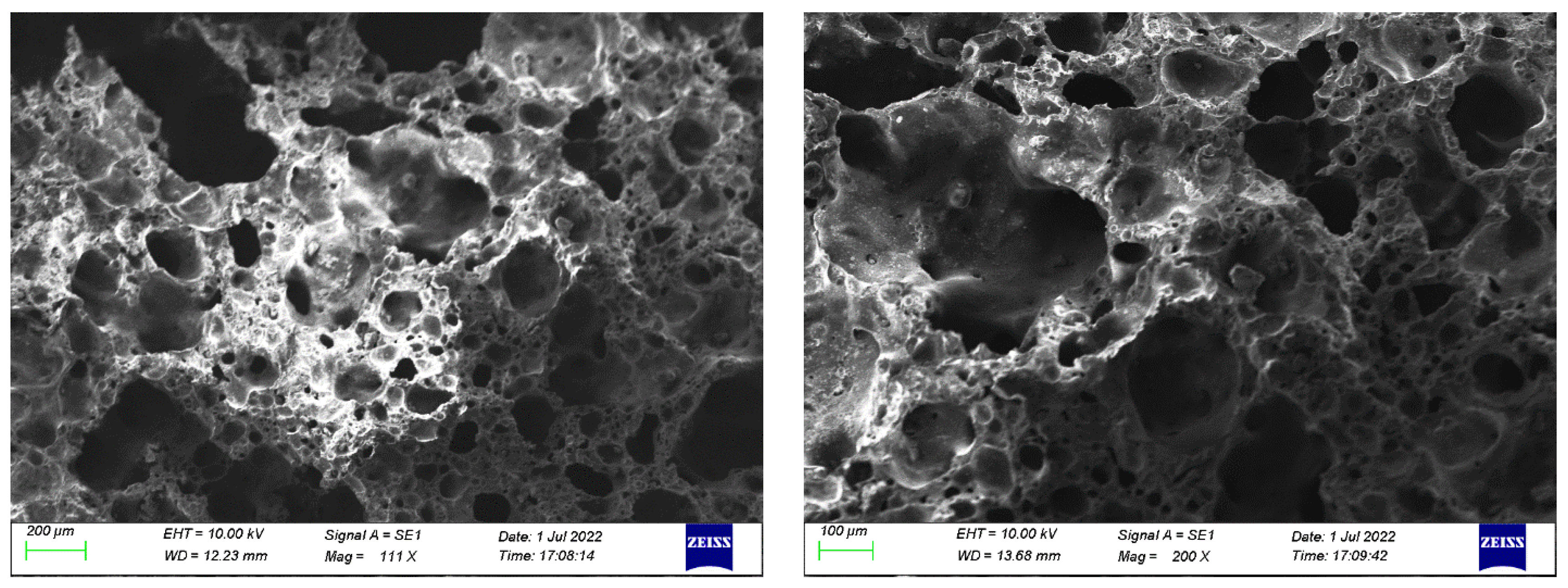
Figure 1. The micro-morphology of shale ceramsite.
Buildings 13 03076 g001
Figure 2. The schematic image of PCM aggregate preparation: (a) raw aggregate, (b) PCM aggregate, (c) PCM aggregate coated by epoxy, (d) PCM aggregate coated by cement, and (e) PCM aggregate after hydration.
Buildings 13 03076 g002
Figure 3. Equipment for measuring the RDEM of concrete specimen.
Buildings 13 03076 g003
Figure 4. Influence of PCM aggregate replacement rate on mechanical properties.
Buildings 13 03076 g004
Figure 5. The relationship between fcu and fst.
Buildings 13 03076 g005
Figure 6. The comparison of fst between fitting equation and recommended equation.
Buildings 13 03076 g006
Figure 7. The morphology of concrete under 50, 100, 150, 200 freeze–thaw cycles.
Buildings 13 03076 g007
Figure 8. Mass loss rate of concrete after freeze–thaw cycles.
Buildings 13 03076 g008
Figure 9. RDEM loss of concrete after freeze–thaw cycles.
Buildings 13 03076 g009
Figure 10. fcu loss of concrete after freeze–thaw cycles.
Buildings 13 03076 g010
Figure 11. T2 spectrum of different PCM aggregate concrete.
Buildings 13 03076 g011
Figure 12. T2 spectrum area of different PCM aggregate concrete.
Buildings 13 03076 g012
Figure 13. Pore volume proportion of different PCM aggregate concrete.
Buildings 13 03076 g013
Table 1. Elementary properties of shale ceramsite.
AggregateApparent Density
(kg/m3)
Loose Bulk Density
(kg/m3)
Crushing Index
(%)
24 h Water Absorption
(%)
Mud Content
(%)
Water Content
(%)
Shale ceramsite150487328.6710.300.870.01
Table 2. Thermal properties of PCMs.
PCMDensity
(g/mL)
Solidifying Temperature
(°C)
Solidifying
Heat Latent
(J/g)
Melting Temperature
(°C)
Melting Heat Latent
(J/g)
Dodecane0.7487−12.86200.5−10.96199.8
Tridecane0.7560−7.84142.9−7.26139.0
Tetradecane0.76284.26206.34.85212.4
Table 3. The relative amount for each component of PCM aggregate (wt.).
Shale CeramsitePCMEpoxy LayerCement Layer
59.62%10.31%9.10%20.97%
Table 4. The latent heat of PCM aggregate (J/g).
Dodecane AggregateTridecane AggregateTetradecane Aggregate
20.6714.7321.67
Table 5. The mixing ratio and density of concrete (kg/m3).
MixCementSandGravelStepwise PCM AggregateWaterSP
C-1550652108001765.5
C-2550652864112 1765.5
C-3550652648224 1765.5
C-4550652432336 1765.5
C-5550652216448 1765.5
C-65506520560 1765.5
Table 6. The difference of fitted value and theoretical value.
PCM Aggregate Replacement RateACICEBAS
0%10.73%12.93%−24.93%
20%15.74%15.53%−21.53%
40%19.22%17.31%−19.17%
60%21.11%18.26%−17.89%
80%24.38%19.89%−15.68%
100%27.03%21.20%−13.88%
Disclaimer/Publisher’s Note: The statements, opinions and data contained in all publications are solely those of the individual author(s) and contributor(s) and not of MDPI and/or the editor(s). MDPI and/or the editor(s) disclaim responsibility for any injury to people or property resulting from any ideas, methods, instructions or products referred to in the content.