Article

Experimental Investigation and Numerical Simulation of Corrugated Steel Plate Shear Wall Considering the Gravity Load

1
Tianjin Key Laboratory of Civil Structure Protection and Reinforcement, Tianjin Chengjian University, Tianjin 300384, China
2
School of Civil Engineering, Tianjin University, Tianjin 300072, China
3
Guangdong Key Laboratory of Earthquake Engineering and Application Technology, Guangzhou University, Guangzhou 510405, China
4
Tianjin Construction Engineering Co., Ltd. of China Railway First Engineering Group, Tianjin 300250, China
5
School of Transportation Science and Engineering, Civil Aviation University of China, Tianjin 300300, China
*
Authors to whom correspondence should be addressed.
Buildings 2023, 13(2), 346; https://doi.org/10.3390/buildings13020346
Submission received: 13 December 2022 / Revised: 15 January 2023 / Accepted: 23 January 2023 / Published: 26 January 2023
(This article belongs to the Section Building Structures)

Abstract

:
The corrugated steel plate shear wall (CSPSW) has high strength, ductility, and energy dissipation capacity and can be used as the lateral force-resisting system of multi-story and high-rise buildings. The vertical load transmitted by the upper floor and frame columns may inevitably act on the corrugated steel plate shear wall. However, the influence of the gravity load on the performance of the corrugated steel shear wall is not considered in most studies. To investigate the behavior of corrugated steel plate shear walls considering the actual gravity load, four scaled SPSWs under lateral and vertical loading were tested. The specimens’ failure mode, envelope curves, and hysteretic curves were analyzed. A numerical simulation model was established based on the validation of the experimental test on the SPSWs. The results showed that the hysteresis curves of the test were consistent with those of the simulation results. Finally, parametric analysis was conducted on the SPSWs with different types of infill plates, height-to-thickness ratio, and gravity loads.

1. Introduction

Compared with the flat steel plate, the corrugated steel plate, which is a kind of steel plate with a corrugated geometric cross-section, carries higher out-of-plane stiffness and higher out-of-plane buckling strength. The corrugated steel plate shear wall (CSPSW) is formed by introducing the corrugated steel plate into the steel plate shear wall. The CSPSW has high lateral stiffness, high bearing capacity, and energy dissipation capacity [1], it can be utilized as the lateral force-resisting system for multi-story and tall buildings.
The mechanical properties of the CSPSW have been extensively studied by researchers through theoretical analysis, numerical simulation, and experiments. Berman and Bruneau [2] carried out the quasi-static test of inclined CSPSW. The test found that the ductility and lateral stiffness of the structure with inclined CSPSW can be improved, but the hysteretic curve may be asymmetric and exist the pinch phenomenon. Emami et al. [3] conducted experimental studies on the SPSWs with unstiffened and trapezoidal corrugated panels. The seismic performance of the trapezoidal corrugated specimens, including energy dissipation capacity, ductility ratio, and initial stiffness, are better than the unstiffened specimen [3]. However, gravity loads were not considered in this research. Zhao et al. [4] conducted the quasi-static tests on three 1/3-scaled two-story single-bay trapezoidal CSPSW specimens with different corrugation orientations and different geometric properties of corrugation. The trapezoidal corrugated steel panel can effectively improve the elastic buckling capacity and lateral stiffness of the shear wall system. Ding et al. [5] studied the seismic performance of corrugated steel plate shear walls (CSPSWs) with slits under quasi-static load. By setting vertical slits, the energy dissipation capacity of corrugated steel shear walls can be improved, but the lateral stiffness of the specimens can be reduced. Cao and Huang [6] conducted the experimental study and numerical simulation of CSPSWs under cyclic loading. The elastic buckling of the CSPSWs may be avoided through reasonable design of corrugations. Wang et al. [7] investigated the relationship between out-of-plane stiffness and in-plane stiffness of CSPSW. To assess the matching relationship, the in-plane and out-of-plane stiffness ratio is presented. Yadollahi et al. [8] studied the nonlinear behaviour of the sinusoidal and trapezoidal corrugated SPSWs under the lateral pushover loading conditions by numerical simulation. The simulation results found that the property of the trapezoidal CSPSWs is better than sinusoidal CSPSWs. Dou et al. [9] proposed modified formulae for bending rigidities of sinusoidally corrugated panels and presented fitting equations with good accuracy to predict the global and local shear buckling loads based on finite element analyses. It is found that the repeating number of corrugations is an important parameter that can affect the shear buckling load, but it was not considered in the previous research. Zhao et al. [10] carried out nonlinear push-over and cyclic loading simulated analysis by finite element model of SPSWs with corrugations and flat plates to investigate the load-carrying mechanism and seismic behavior of CSPSWs. The results show that CSPSWs with deeper corrugations have higher lateral stiffness, lateral strength, and energy dissipation capacity than SPSWs, while CSPSWs with shallower corrugations have higher lateral stiffness and ductility, but have lower lateral strength than SPSWs. Farzampour et al. [11,12] studied the influence of the existence of an opening on the corrugated steel shear walls by finite element analysis. The performance of CSPSWs with openings was better than the corresponding simple SPSWs. Deng et al. established a high-efficiency analysis model of CSPSWs for the modular steel structure [13], which can be utilized to simulate of CSPSWs both with and without openings. Zhao et al. [14] proposed an improved empirical formula for the basic period of corrugated steel plate shear walls based on regression analyses. Feng et al. [15] studied the elastic buckling behavior of vertical trapezoidal CSPSWs stiffened by horizontal steel strips. A theoretical model consisting of an orthotropic plate with elastically torsional restrained edges was presented, and it was verified by finite element analyses.
Based on the corrugated steel plate shear walls, some novel steel plate walls were proposed to improve seismic performance. Tan et al. proposed novel steel plate wall-corrugated SPSWs with vertical zigzag corrugations [16] and a semicircular CSPSW [17] and investigated the performance of CSPSWs by the low-frequency cycle loading test and FEA analysis. Wang et al. [18] conducted the experimental study of CSPSWs and the composite shear walls reinforced by corrugated steel plates. The test results demonstrated that the hysteretic behavior of the SPCSWs is better than that of the SPSW. Broujerdian et al. [19] proposed a compound section for steel shear walls by combining corrugated and flat panels. The proposed wall, in which the double corrugated plates are covered by two sides of flat plates, can improve the seismic performance of the conventional SPSW and reduce stress in the main frame. Ghodratian-Kashan and Maleki [20] designed double-corrugated SPSWs, which consist of two similar corrugated steel plates placed symmetrically and bolted together at contact points with uniform spacing, and they studied the cyclic performance using nonlinear material and geometry options available in ABAQUS. The cyclic behavior of the dual CSPSWs can be effectively improved by increasing the panel aspect ratio. Ma et al. [21] proposed two types of stiffened CSPSWs and studied the seismic performance under atmospheric corrosion by finite element analyses using ABAQUS. The stiffeners can enhance the seismic performance of CSPSWs.
Although many experimental and theoretical investigations have been carried out on CSPSWs, the most of the existing studies concentrated on the performance under cyclic lateral loads. Little research on the behavior of CSPSWs under actual gravity and cyclic loads was taken into account. To investigate the performance of corrugated steel plate shear walls with the actual gravity load, four scaled SPSWs with lateral and vertical loading were tested. The impacts of the actual gravity load on the properties of the SPSW were investigated and validated by the test results.

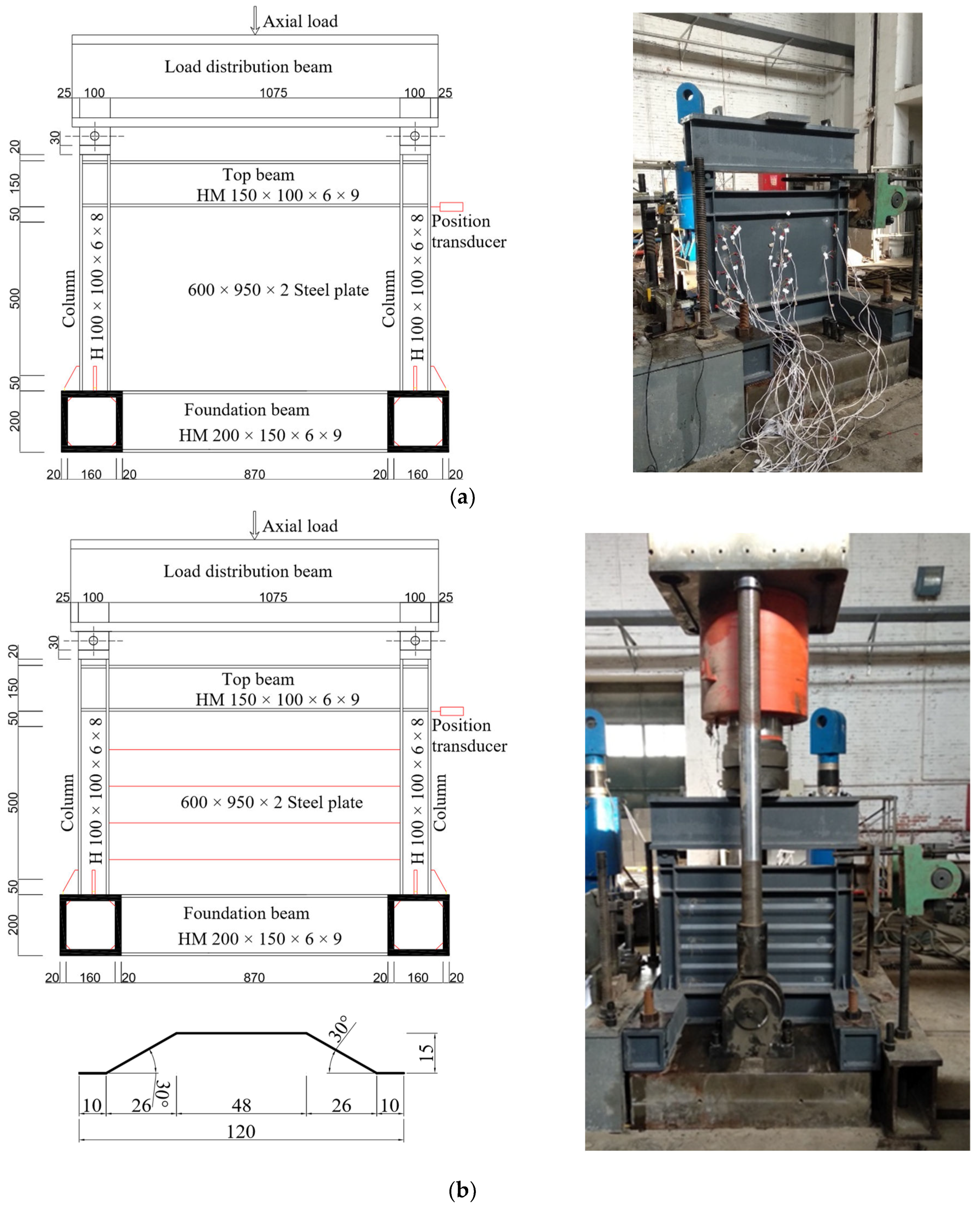
2. Experimental Design

The four specimens are one-storey walls. The height of the specimens is 0.75 m, and the width is 1.1 m. The length between the axes of the columns is 1 m. The parameters of the four structural models are shown in Figure 1. Specimens A and C, shown in Figure 1a, were built up with flat steel plates, and specimens B and D, shown in Figure 1b, were built up with corrugated steel plates. The angle of corrugation in the trapezoidal plate is 30°, the depth of corrugation in the corrugated SPSW is 15 mm, and the width of the horizontal panel in the trapezoidal plate is 48 mm. The plates are made of Q235 steel and have a thickness of 2 mm. The dimension of the infill panel was 600 mm × 950 mm. The design parameters of the four structural models are exhibited in Table 1. The columns and beams of the frame are H sections made of Q390 steel. For the columns, the H-overall depth (d) of H-section steel was 100 mm, the flange width (bf) of H-section steel was 100 mm, the web thickness (tw) of H-section steel was 6 mm, and the flange thickness (tf) of H-section steel was 8 mm. For the top beam, the H-overall depth (d) of H-section steel was 150 mm, the flange width (bf) of H-section steel was 100 mm, the web thickness (tw) of H-section steel was 6 mm, and the flange thickness (tf) of H-section steel was 9 mm. This top beam was stiff to ensure the load smoothly transferred to the tension zone that appeared under the beam. The beam-to-column joints are all moment connections.
To simulate the gravity load, a vertical load was applied through a hydraulic actuator which acts on the load distribution beam. During loading, the vertical load was unchanged. The lateral actuator was supported by the reaction wall in the laboratory. The cyclic loads in the horizontal direction were applied by the lateral hydraulic actuator on the top beam. A constant vertical load of 486 kN was applied at the top of the load distribution beam, which resulted in the axial stress being about 100 MPa acting on the column of specimens A and B. Specimens C and D were used as reference specimens in this work, so there was no vertical load applied to them, and only horizontal load was applied by the lateral hydraulic actuator. Figure 1 shows the test setup.
The force- and displacement-controlled loading method was adopted in this work. Before steel panels yielded, a force-controlled load in the lateral direction was applied. The load was applied by increasing with an increment of 50 kN. When an obvious inflection point appeared in the force–displacement curve, it meant that the specimens were yielding. After the specimens were yielded, the loading protocol was not the same as any existing research, codes, or standards. In the push direction, displacement-controlled loading was conducted until the specimens failed. Each displacement was repeated in three cycles, whereas the specimens were loaded by a maximum load of 100 kN in the pull direction. Since most of the structures under seismic action may not go back to the initial position due to the randomness of the earthquake ground motions, this loading protocol was adopted.
The mechanical characteristics of the steel panels and the H-type section steel of beams and columns selected in the specimens are shown in Table 2. The yield stresses, ultimate stresses, and elongation of Q235 and Q390 steels are 232 MPa and 456 MPa, 376 MPa and 562 MPa, and 18.3% and 21.4%, respectively. The actual properties of each material in the experiment were obtained by the coupon tests according to the Chinese standards of GB/T2975-2018 [23].

3. Experimental Results

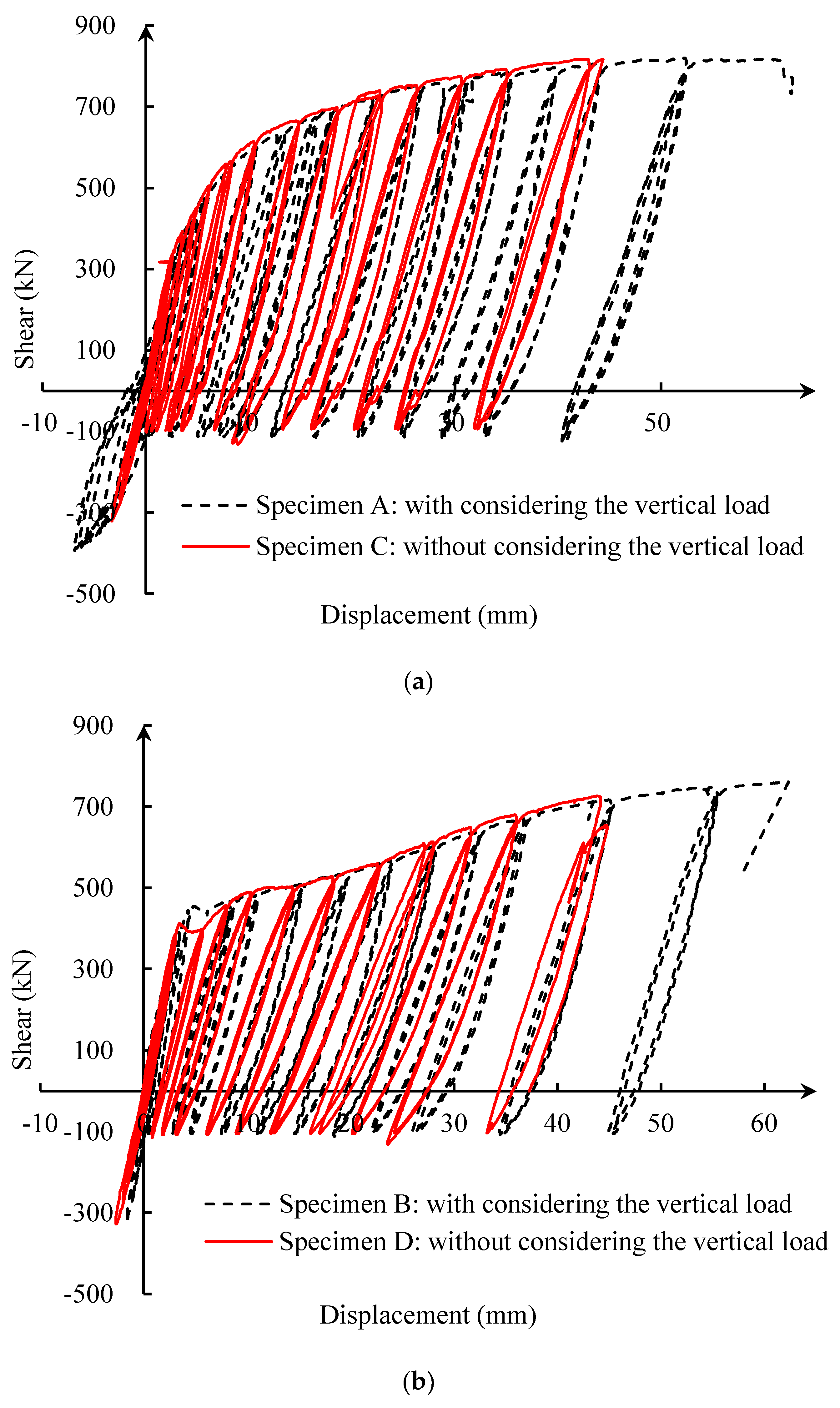
3.1. Hysteretic Curve

Figure 2 shows the hysteretic curves of the specimens with different infill steel plates under different loadings. The results indicated that the effect of the actual gravity load on the hysteretic curve of the walls was not obvious. Figure 2a shows the hysteric curves of the flat SPSWs without and with loading vertically. For the flat SPSW with the vertical load, the maximum deformation was about 63.33 mm, and the corresponding storey drift was 9.74%. For the flat SPWS without the load in the vertical direction, the maximum deformation was about 44.38 mm, and the corresponding storey drift was 6.83%. When the load in the horizontal direction was less than 300 kN, the relationship between shear and deformation was almost linear. The yielding point in the hysteretic curves was not very apparent. After the specimen was yielded, the unloading and reloading stiffness may slightly decrease. As the load applied in the pull direction was only 100 kN, an obvious unrecoverable deformation may be formed in the test. With the displacement of the specimens increasing, unrecoverable deformation increased. The hysteric curves of the CSPSWs without and with loading vertically are shown in Figure 2b. For the corrugated SPSW with the vertical load, the maximum deformation was about 62.34 mm, and the corresponding storey drift was 13.01%. For the corrugated SPSW without the vertical load, the maximum deformation was about 44.32 mm, and the corresponding storey drift was 12.63%. Compared with specimen C, the shear strength of specimen A decreased by about 14%, whereas for the corrugated SPSWs, the shear strength of specimen B decreased by only about 3.2% compared with that of specimen D. The effect of the vertical load on the horizontal CSPSWs is less than the flat SPSWs.
According to the comparison between the force–displacement curves of specimens A and B, the horizontal CSPSW (specimen B) has better energy dissipation capacity under lateral and vertical load. Although the bearing capacity of the horizontal CSPSW, which was numbered specimen B, was slightly less than the conventional flat SPSW, which was numbered specimen A, the yield displacement and ultimate displacement of the horizontal CSPSW (specimen B) are larger than those of the flat SPSW (specimen A).

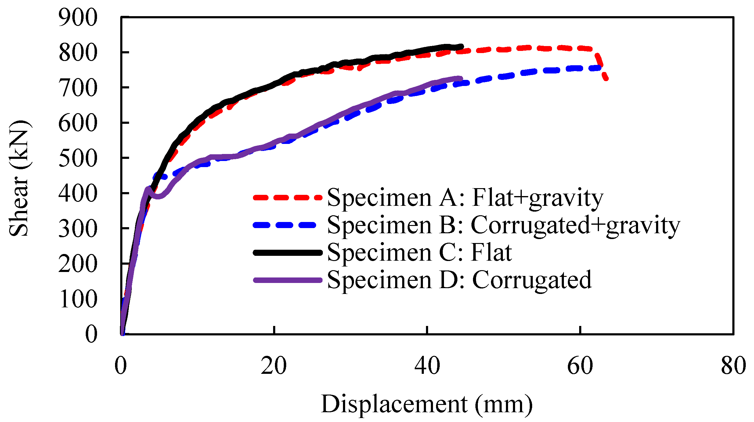
3.2. Envelope Curves

Figure 3 shows the envelope curves of the four SPSWs with different infill steel panels under different loadings. It found that a yield plateau can be observed in the envelope curve of the corrugated SPSW. The results are shown in Table 3, including the stiffness, strength, the corresponding deformation at the yielding strength and the ultimate strength, and so on. For the flat SPSW with the vertical load (specimen A), the yielding displacement was 6.75 mm, the yield force was 507.8 kN, and the corresponding yield inter-story drift was 1.038%. For the corrugated SPSW with the vertical load (specimen B), the yield displacement was 4.79 mm, the yield force was 453.06 kN, and the corresponding yield inter-story drift was 0.737%. The yield displacement of the flat SPSW without the vertical load (specimen C) is 6.58 mm, the yield force is 520.5 kN, and the corresponding yield inter-story drift was 1.012%. For the corrugated SPSW without loading in the vertical direction (specimen D), the yield force was 412.4 kN, the corresponding displacement of the yielding point was 3.51 mm, and the corresponding yield inter-story drift was 0.54%. Before the infill plate of the SPSW buckling, the stiffness and the shear strength of the horizontal CSPSW were almost the same as the flat SPSW. The shear displacement remained a linear increase versus the applied shear force. After the infill plate of the SPSW buckling, the shear strength of the horizontal CSPSW was less than the flat SPSW. A small yield plateau can be observed in the shear–displacement curve of the horizontal CSPSW. The plateau is caused by the gradual flattening of corrugations. The corrugations of horizontal CSPSWs can increase the deformation adaptability. With the increase in displacement, the shear force increased and the tension field of the horizontal CSPSW was developed until the test finished.

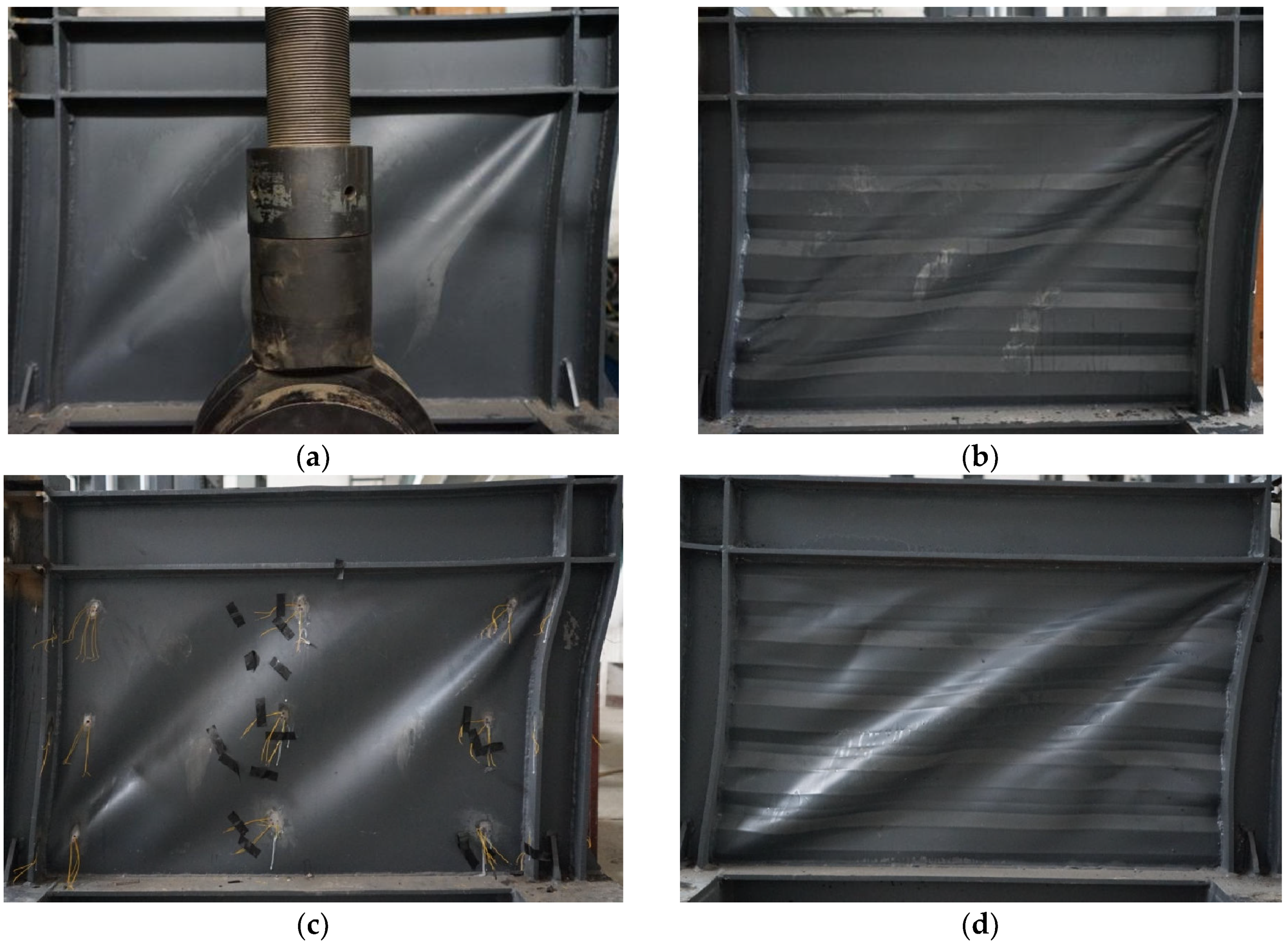
3.3. Specimens’ Behaviour

To investigate the actual gravity load impact on the seismic behavior of SPSWs, a vertical load was first applied to the distribution beam of specimens A and B. In this experimental test, the load was 480 kN. The value of the vertical load should be constant during the test. As the vertical load is constant, the vertical stress caused by the vertical load may be generated with 100 MPa. When the specimens were loaded only with the gravity loads, no buckling in SPSWs (specimens A and B) with flat and horizontal corrugation plates appeared. Then, the cyclic load in the lateral direction was applied by the horizontal hydraulic actuator.
The ultimate failure modes of the four specimens are shown in Figure 4. The vertical load applied to the specimens had little effect on the failure mode of the SPSWs. Compared with the flat SPSW, the deformation capacity of the horizontal corrugated SPSW was larger. Before the strips of tension field were produced, the corrugations of the horizontal CSPSW may be stretched, and the direction of the strips was along a diagonal line from the lower left corner to the upper right corner. However, when the test was finished, the corrugations of the horizontal CSPSW were not stretched to be flat.
Taking specimen A (the SPSW with flat panel) as an example, the buckling of the flat panel did not occur when the top displacement was 4 mm. The tension field strips may be formed, which were inclined, and the inclination angle of the strips was about 45°, as shown in Figure 4a. When the lateral load reached 300 kN for the first time, the specimen produced a loud bang. In the following cycles, the specimen would continue to make loud bangs. As the top displacement increased, the infill steel plate gradually began to yield. At the end of each cycle, the specimen had a large residual deformation. With the increase in loading cycle number, the residual deformation increased. There were no cracks formed during the whole test. The ultimate deformation of the flat SPSW was large than 62 mm, whereas the shear bearing capacity of the flat SPSW was reduced by about 15%. When the test finished, local buckling may be formed in the flange of the compression column, and there was only a slight out-of-plane deformation formed in the flat SPSW.

4. Numerical Simulation

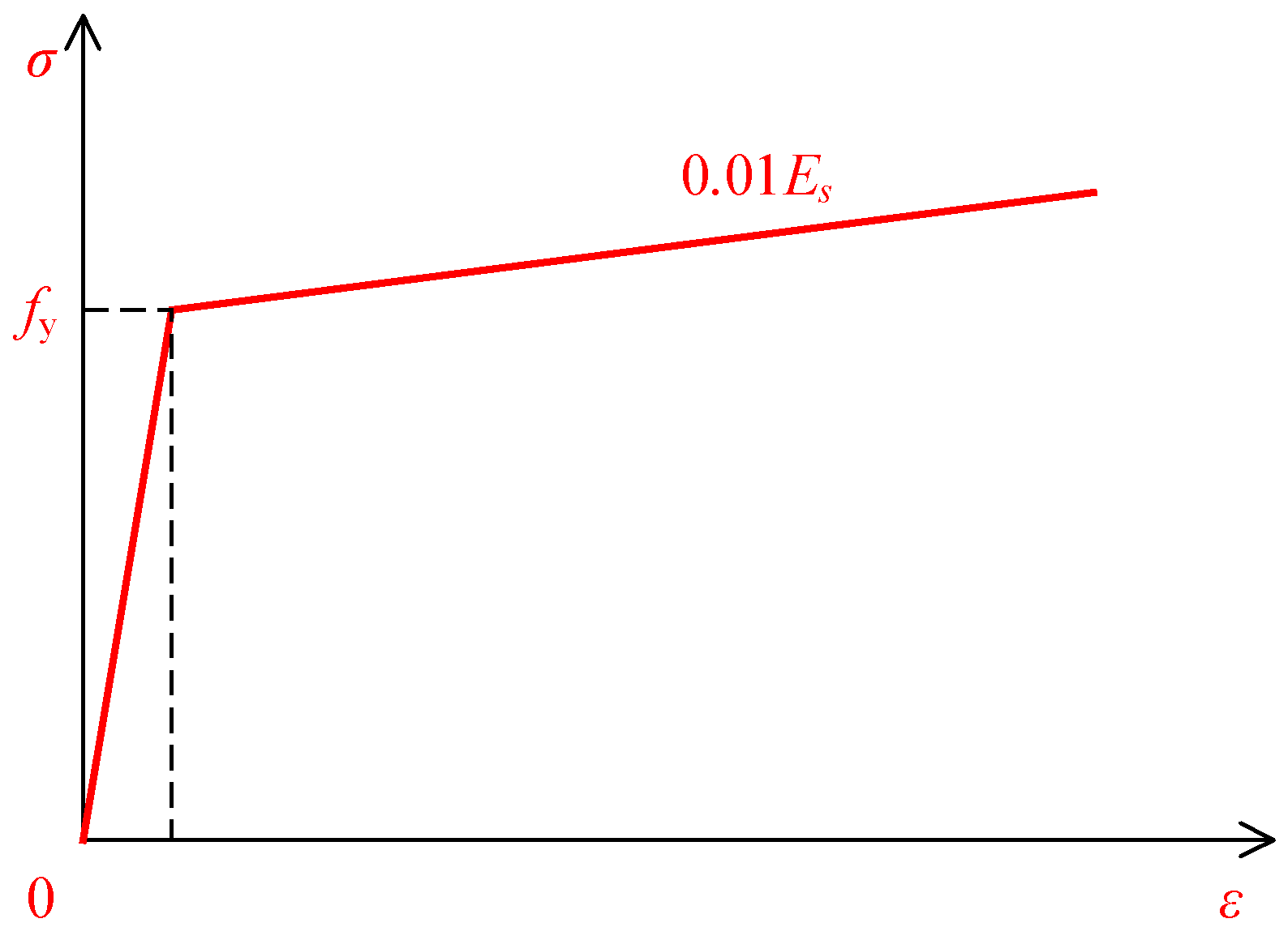
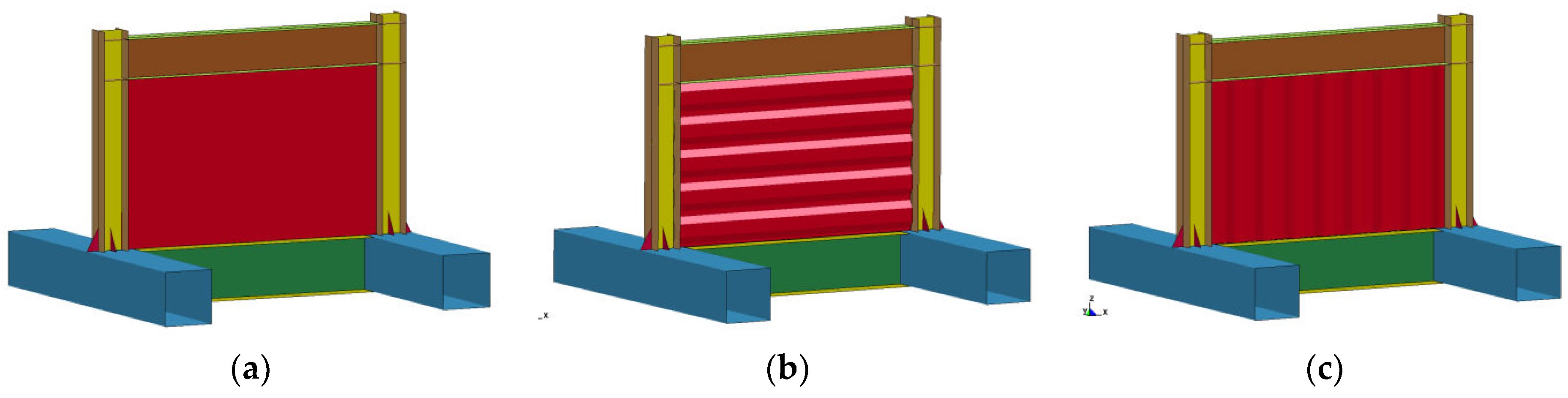
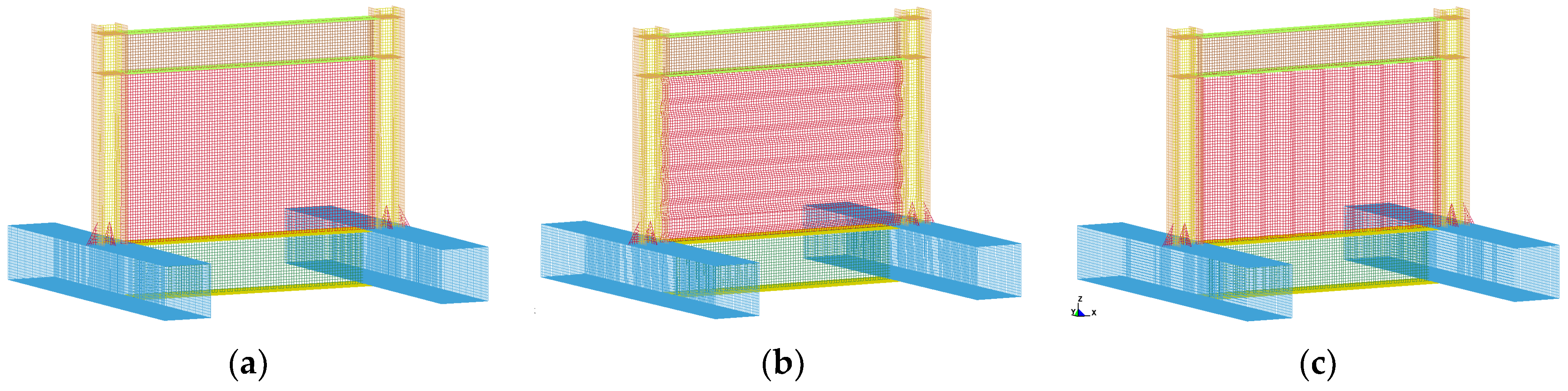
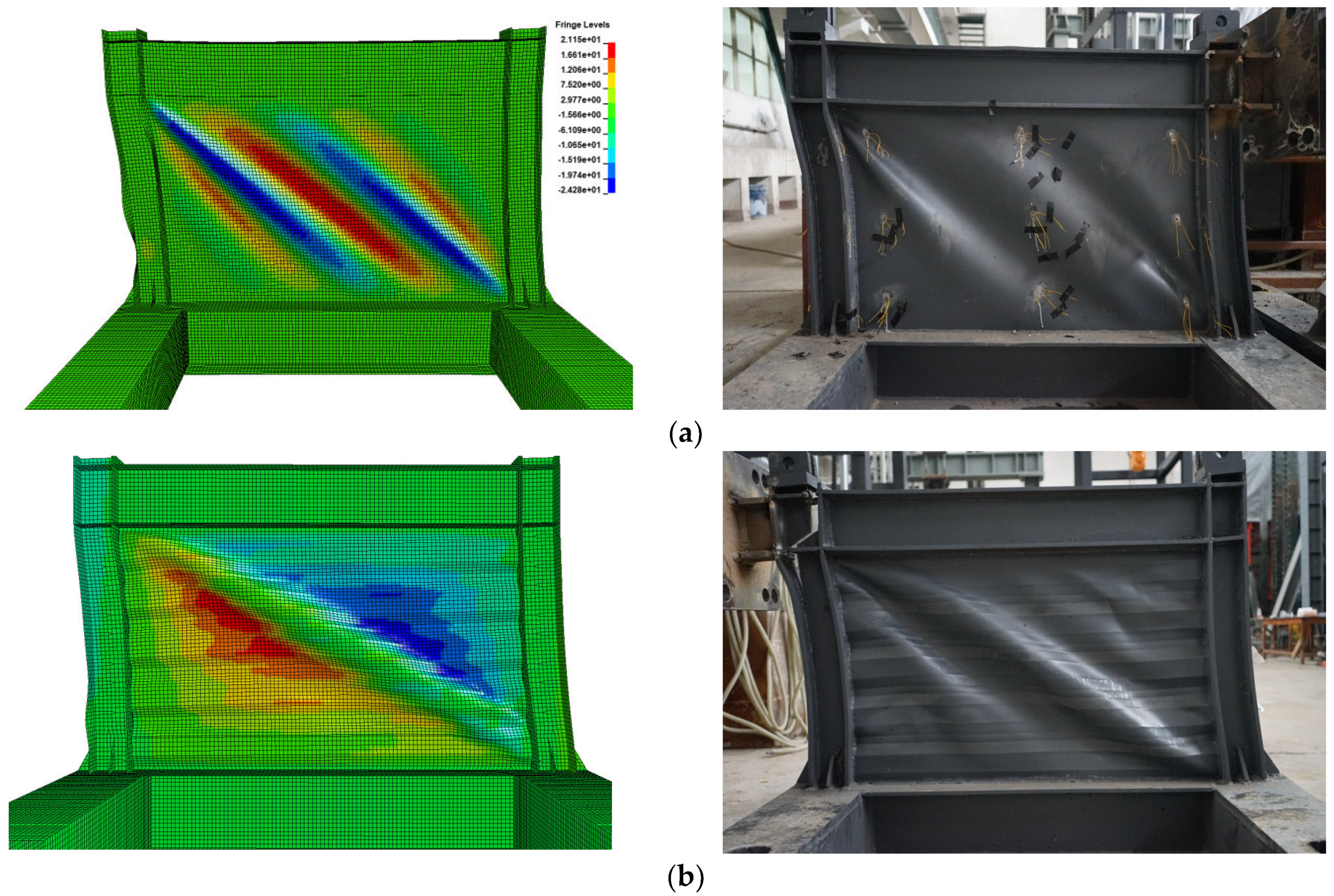
4.1. Numerical Model and Verification

A numerical model was established with the general-purpose finite element software ANSYS adopting layered shell elements. The plastic-kinematic model was selected as shown in Figure 5 to simulate the property of the steel. The yield strength of different steels was the same as those obtained from material tests. After yielding, the strain hardening modulus in the stress–strain relationship is 1% of the elastic modulus Es. Besides the steel plate shear walls with flat infill plates and horizontal corrugated infill plates designed in the test, the vertical corrugated infill plates were also analyzed by the finite element model. Figure 6 shows the SPSWs models with three types of infill plates, including a flat panel (Figure 6a), a horizontal corrugated panel (Figure 6b), and a vertical corrugated panel (Figure 6c). The corresponding finite element models are shown in Figure 7. The initial imperfection of the wall was considered by the first mode shape with a maximum out-of-plane deformation of 1/500 of the wall height.
Figure 8 shows the simulation results of specimens C and D. Figure 8a is the simulation results of the flat SPSW (specimen C), and Figure 8b is the simulation results of the horizontal corrugated SPSW (specimen D). The pushover curves of specimens C and D, obtained by the FEM analysis, are also exhibited in Figure 8. It was found that the hysteresis curves of the test were consistent with those of the simulation results. The shear strengths of the SPSWs obtained from the pushover curve were a little higher than those of the experimental and numerical simulation results.
Figure 9a shows the failure mode of the flat SPSW (specimen C), and Figure 9b shows the failure mode of the horizontal corrugated SPSW (specimen D). Comparing the failure mode of numerical simulation with that of the test, the finite element model may efficiently simulate the behavior of the steel plate shear walls. So, the finite element model may be verified by the experimental test and can be utilized to predicate the behavior of the SPSWs with different infill panels.

4.2. Parametric Analysis

Many parameters may affect the performance of the SPSWs. In this section, the influence of the types of infill steel panels, the height-to-thickness ratio, and the axial stress caused by the actual gravity load on SPSWs are investigated. Table 4 shows the parameters considered. For the considered axial stresses, the parameter varied from 50 MPa to 200 MPa, increasing with a 50 MPa interval. For the height-to-thickness ratio, when the ratio is 300, the corresponding thickness of the plate should be 2 mm. When the ratio was 150, the corresponding thickness of the plate should be 4 mm. When the ratio was 100, the corresponding thickness of the plates should be 6 mm. The geometric dimensions of the SPSWs for parametric analysis are the same as the specimens used in the tests. The pushover analyses of the SPSWs with three types of infill plates were carried out.

4.3. Infill Steel Plate
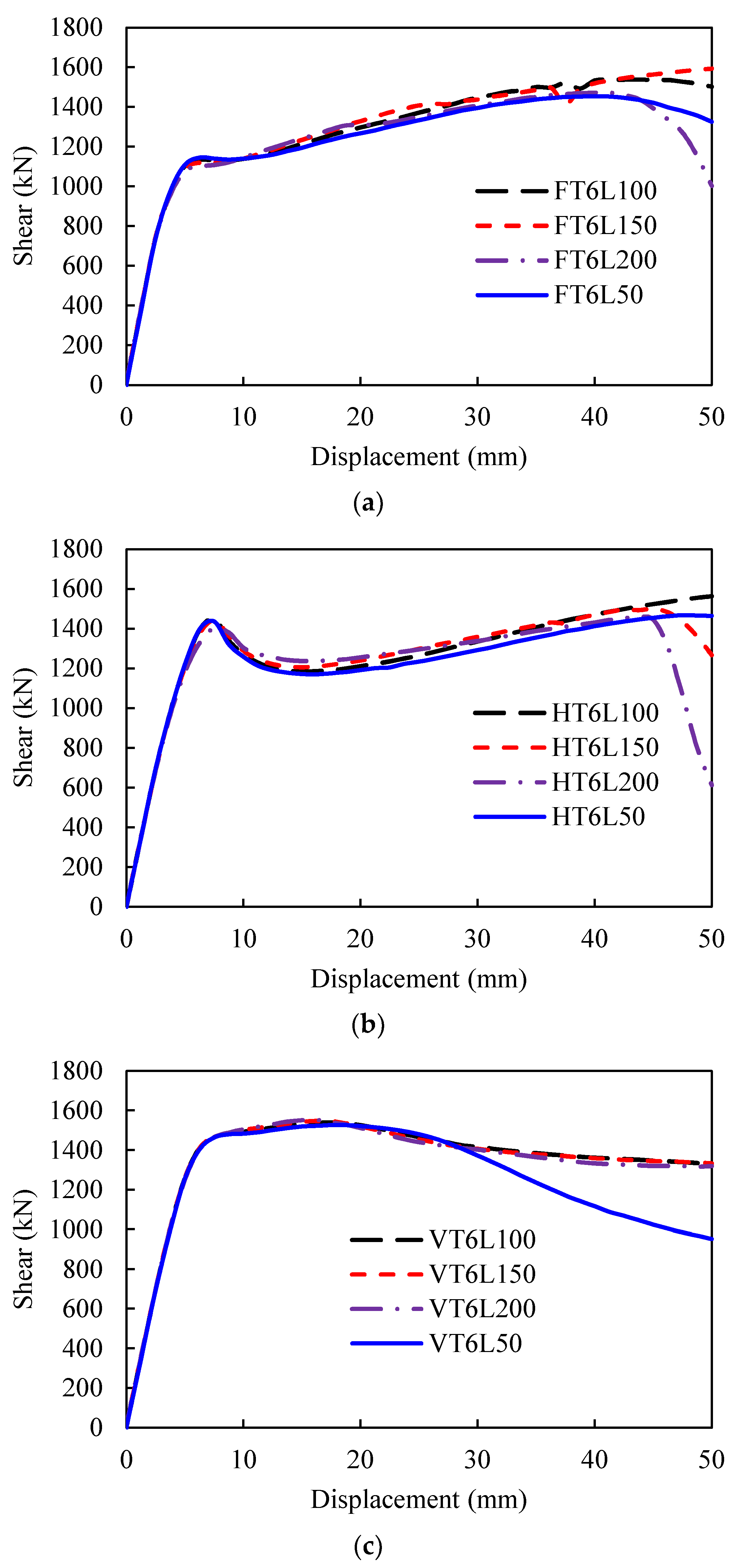
Figure 10 shows the shear force–displacement curves of the SPSWs with a thickness of 4 mm in which the axial stresses formed under the vertical load were 50 MPa (solid line) and 200 MPa (dashed line). For SPSWs with different types of infill panels, the shear force–displacement curves were different. When the infill panel was flat, the shear increased with the increase in displacement, whereas when the infill panel was corrugated, the shear–displacement curve experienced three stages, i.e., elastic increase, decrease, and increase phase. When buckling of the SPSWs occurred, the shear strength of the flat SPSW was less than that of the horizontal and vertical corrugated SPSW. After buckling of the SPSW appeared, the displacement increased, while the shear of the vertical and horizontal CSPSW started to decrease. The buckling strength of the vertical CSPSW was higher than that of the horizontal CSPSW. At the second stage of the shear force–displacement relationship of CSPSWs, the shear force of the horizontal CSPSW decreased lower than that of the horizontal CSPSW. The corrugations of corrugated SPSWs were gradually stretched with the increase in displacement, and then the shear force of the CSPSW started to increase. For the horizontal corrugated SPSW, the shear force began to increase when the displacement was 12 mm, while for the vertical CSPSW, the shear force increased when the displacement was 26 mm. When the displacement of corrugated SPSWs under axial stress of 50 MPa was about 30 mm, the shear of the horizontal CSPSW was almost equal to that of the vertical CSPSW. When the displacement of the CSPSW was over 30 mm, under the axial stress of 50 MPa, the shear force of the vertical CSPSW increased faster than that of the horizontal CSPSW. Among the three types of infill steel plates, the shear capacity of the flat SPSW was the largest. The axial stress caused by the actual gravity load may affect the shear-bearing capacity of the SPSWs. Before the buckling of SPSWs, the influence of the axial stress formed by loading vertically on the flat SPSW was more significant than that on the corrugated SPSW. After buckling of SPSWs, the impact of the axial stress caused by loading vertically on the horizontal CSPSW was larger than that of other types of infill plates. For the vertical corrugated SPSW, the influence of the actual gravity load was not significant.

4.4. Vertical Load

For the SPSWs with a thickness of 6 mm (the corresponding height-to-thickness ratio is 100) under different axial stress, the relationship between shear and displacement is shown in Figure 11. For the SPSWs with a thickness of 4 mm (the corresponding height-to-thickness ratio is 150) under different axial stress, the relationship between shear and displacement is shown in Figure 12. For the SPSWs with a thickness of 2 mm (the corresponding height-to-thickness ratio is 200) under different axial stress, the relationship between shear and displacement is shown in Figure 13. The shear strength of SPSWs with different types and thicknesses of infill plates under different vertical loads are listed in Table 5. The results demonstrated that the impact of the gravity load on a thick SPSW was larger than that of a thin SPSW. As shown in Table 5, for the flat SPSW with a thickness of 6 mm (FT6), when the axial stress increased from 50 MPa to 100 MPa, the shear strength decreased by about 0.52%. When the axial stress varied from 100 MPa to 150 MPa, the shear strength decreased by about 1.57%. When the axial stress varied from 150 MPa to 200 MPa, the shear strength decreased by about 2.96%. For the horizontal CSPSW with a thickness of 2 mm (HT2), when the axial stress caused by loading vertically increased from 50 MPa to 100 MPa, the shear strength of HT2 decreased by about 0.57%. When the axial stress increased from 100 MPa to 150 MPa, the shear strength of HT2 decreased by about 1.48%. When the axial stress increased from 150 MPa to 200 MPa, the shear strength of HT2 decreased by 2.34%. For the vertical CSPSW with a thickness of 4 mm (VT4), there was almost no difference in shear strength with the increase in axial stress.

5. Conclusions

Many theoretical and experimental investigations of CSPSWs have been carried out to study the seismic behavior of SPSWs under cyclic loads, but the actual gravity load of the SPSWs was not considered in most references. To investigate the seismic behavior of CSPSWs considering the actual gravity load, the experimental tests of four scaled SPSWs with flat and corrugated panels under cyclic loading and the constant vertical load were conducted. The simulation analysis of SPSWs with three types of infill plates considering the gravity load was carried out. The following conclusions can be obtained:
  • The corrugation of SPSWs increases the shear deformation adaptability. For the corrugated SPSWs, the shear–displacement curve has a small yield plateau formed by the gradual flattening of the corrugations.
  • A numerical model was proposed to simulate the SPSWs with the actual gravity load, and the effectiveness of the proposed model was validated by the experimental results.
  • Considering the gravity load, the yield force of the vertical CSPSW (VT4), horizontal CSPSW (HT4), and flat SPSW (FT4) were 1005.75 kN, 851.66 kN, and 708.6 kN, respectively. The performance of the vertical CSPSW may be better than the horizontal CSPSW and flat SPSW. Comparing the shear displacement relation shape of different infill plate types, the effect of the vertical load to simulate the actual gravity load on the horizontal CSPSW is the largest, followed by the flat SPSW and the vertical CSPSW.
  • The shear–displacement curve of the CSPSWs experienced three stages including an elastic stage, a decrease stage, and an increase stage. For vertical CSPSWs with a small height-to-thickness ratio, such as VT6, the shear–displacement curve has a stable post-buckling stage.

Author Contributions

Conceptualization, Y.L.; software, J.G.; validation, Y.C.; formal analysis, J.G.; investigation, F.L.; resources, Y.L.; writing—original draft, F.L.; writing—review and editing, Y.Z., Y.C. and Y.L. All authors have read and agreed to the published version of the manuscript.

Funding

This research was funded by the Scientific Research Program of Tianjin Municipal Education Commission under Grant number 2021KJ059, the Open Research Fund Program of Guangdong Key Laboratory of Earthquake Engineering and Application Technology (Guangzhou University) under grant number 2020B1212060071, and the Opening Project of the Key Laboratory of the Beijing University of Technology under grant number 2022B04.

Institutional Review Board Statement

Not applicable.

Informed Consent Statement

Not applicable.

Data Availability Statement

The data presented in this study are available on request from the corresponding authors.

Conflicts of Interest

The authors declare no conflict of interest.

References

  1. Guo, Y.-l.; Zhu, J.-s. Research progress of shear walls: Types and design methods. Eng. Mech. 2020, 37, 19–33. (In Chinese) [Google Scholar]
  2. Berman, J.W.; Bruneau, M. Experimental Investigation of Light-Gauge Steel Plate Shear Walls. J. Struct. Eng. 2005, 131, 259–267. [Google Scholar] [CrossRef] [Green Version]
  3. Emami, F.; Mofid, M.; Vafai, A. Experimental study on cyclic behavior of trapezoidally corrugated steel shear walls. Eng. Struct. 2013, 48, 750–762. [Google Scholar] [CrossRef]
  4. Qiu, J.; Zhao, Q.H.; Yu, C.; Li, Z. Experimental Studies on Cyclic Behavior of Corrugated Steel Plate Shear Walls. J. Struct. Eng. 2018, 144, 04018200. [Google Scholar] [CrossRef]
  5. Ding, Y.; Deng, E.-f.; Zong, L.; Dai, X.; Lou, N.; Chen, Y. Experimental study on seismic performance of corrugated steel plate shear wall in modular container construction. J. Build. Struct. 2018, 39, 110–118. (In Chinese) [Google Scholar]
  6. Cao, Q.; Huang, J. Experimental study and numerical simulation of corrugated steel plate shear walls subjected to cyclic loads. Thin-Walled Struct. 2018, 127, 306–317. [Google Scholar] [CrossRef]
  7. Wang, W.; Luo, Q.; Sun, Z.; Wang, B.; Xu, S. Relation analysis between out-of-plane and in-plane failure of corrugated steel plate shear wall. Structures 2021, 29, 1522–1536. [Google Scholar] [CrossRef]
  8. Yadollahi, Y.; Pakar, I.; Bayat, M. Evaluation and comparison of behavior of corrugated steel plate shear walls. Lat. Am. J. Solids Struct. 2015, 12, 763–786. [Google Scholar] [CrossRef] [Green Version]
  9. Dou, C.; Jiang, Z.; Pi, Y.; Guo, Y. Elastic shear buckling of sinusoidally corrugated steel plate shear wall. Eng. Struct. 2016, 121, 136–146. [Google Scholar] [CrossRef]
  10. Zhao, Q.; Sun, J.; Li, Y.; Li, Z. Cyclic analyses of corrugated steel plate shear walls. Struct. Des. Tall Spec. Build. 2017, 26, e1351. [Google Scholar] [CrossRef]
  11. Farzampour, A.; Laman, J.A.; Mofid, M. Behavior prediction of corrugated steel plate shear walls with openings. J. Constr. Steel Res. 2015, 114, 258–268. [Google Scholar] [CrossRef]
  12. Farzampour, A.; Mansouri, I.; Hu, J.W. Seismic Behavior Investigation of the Corrugated Steel Shear Walls Considering Variations of Corrugation Geometrical Characteristics. Int. J. Steel Struct. 2018, 18, 1297–1305. [Google Scholar] [CrossRef]
  13. Deng, E.; Zong, L.; Wang, H.; Shi, F.; Ding, Y. High efficiency analysis model for corrugated steel plate shear walls in modular steel construction. Thin-Walled Struct. 2020, 156, 106963. [Google Scholar] [CrossRef]
  14. Zhao, Q.; Qiu, J.; Zhao, Y.; Yu, C. Estimating Fundamental Period of Corrugated Steel Plate Shear Walls. KSCE J. Civ. Eng. 2020, 24, 3023–3033. [Google Scholar] [CrossRef]
  15. Feng, L.; Sun, T.; Ou, J. Elastic buckling analysis of steel-strip-stiffened trapezoidal corrugated steel plate shear walls. J. Constr. Steel Res. 2021, 184, 106833. [Google Scholar] [CrossRef]
  16. Tan, P.; Wei, Y.; Li, Y. Experimental investigation on performance of corrugated steel plate shear wall. China Civ. Eng. J. 2018, 51, 8–15. [Google Scholar]
  17. Tan, P.; Zhou, L.-l.; Teng, X.-f. Hysteretic performance of self-centering steel frame with semicircular corrugated steel plate shear wall with edge stiffeners. J. Build. Struct. 2021, 42, 185–192. (In Chinese) [Google Scholar]
  18. Wang, W.; Ren, Y.; Lu, Z.; Song, L.; Han, B.; Zhou, Y. Experimental study of the hysteretic behaviour of corrugated steel plate shear walls and steel plate reinforced concrete composite shear walls. J. Constr. Steel Res. 2019, 160, 136–152. [Google Scholar] [CrossRef]
  19. Broujerdian, V.; Ghamari, A.; Abbaszadeh, A. Introducing an efficient compound section for steel shear wall using flat and corrugated plates. Structures 2021, 33, 2855–2871. [Google Scholar] [CrossRef]
  20. Ghodratian-Kashan, S.M.; Maleki, S. Numerical Investigation of Double Corrugated Steel Plate Shear Walls. J. Civ. Eng. Constr. 2021, 10, 44–58. [Google Scholar] [CrossRef]
  21. Ma, X.; Hu, Y.; Jiang, L.; Jiang, L.; Nie, G.; Zheng, H. Study on the Seismic Performance of stiffened corrugated steel plate shear walls with atmospheric corrosion. Materials 2022, 15, 4920. [Google Scholar] [CrossRef] [PubMed]
  22. Yang, L. Steel Plate Shear Walls with Gravity Load: Theory and Design; Springer: Singapor, 2022. [Google Scholar]
  23. GB/T2975-2018; Steel and Steel Products-Location and Preparation of Test Pieces for Mechanical Testing. China Standards Press: Beijing, China, 2018. (In Chinese)
Figure 1. Dimensions and test set-up (units: mm); (a) specimens A and C; (b) specimens B and D (Adapted with permission from Ref. [22]. Copyright 2022 Springer Nature).
Buildings 13 00346 g001
Figure 2. Hysteretic curves of specimens with and without the vertical load: (a) flat wall and (b) corrugated wall. (Adapted with permission from Ref. [22]. Copyright 2022 Springer Nature).
Buildings 13 00346 g002
Figure 3. Envelope curves of specimens A, B, C, and D. (Adapted with permission from Ref. [22]. Copyright 2022 Springer Nature).
Buildings 13 00346 g003
Figure 4. Failure mode of specimens (a) A, (b) B, (c) C, and (d) D.
Buildings 13 00346 g004
Figure 5. Material model of steel. (Adapted with permission from Ref. [22]. Copyright 2022 Springer Nature).
Buildings 13 00346 g005
Figure 6. Simulated walls with (a) flat, (b) horizontal corrugated, and (c) vertical corrugated steel plate.
Buildings 13 00346 g006
Figure 7. FEM of the walls with (a) flat, (b) horizontal corrugated, and (c) vertical corrugated steel plate.
Buildings 13 00346 g007
Figure 8. Comparison of the simulation and test results for specimens (a) C and (b) D. (Adapted with permission from Ref. [22]. Copyright 2022 Springer Nature).
Buildings 13 00346 g008
Figure 9. Comparison of the final failure of specimens (a) C and (b) D.
Buildings 13 00346 g009
Figure 10. Shear–displacement relationship of different infill plate types. (Adapted with permission from Ref. [22]. Copyright 2022 Springer Nature).
Buildings 13 00346 g010
Figure 11. Effect of vertical load on the SPSWs with a thickness of 6 mm and a (a) flat, (b) horizontal corrugated, and (c) vertical corrugated plates.
Buildings 13 00346 g011
Figure 12. Effect of vertical load on the SPSWs with a thickness of 4 mm and a (a) flat, (b) horizontal corrugated, and (c) vertical corrugated plates.
Buildings 13 00346 g012
Figure 13. Effect of vertical load on the SPSWs with a thickness of 2 mm and a (a) flat, (b) horizontal corrugated, and (c) vertical corrugated plates.
Buildings 13 00346 g013
Table 1. Parameters of the steel plate shear wall.
SpecimenConfigurationPlate Thickness (mm)Plate Size (mm)Top BeamColumn
Aflat steel plate2600 × 950HM150 × 100 × 6 × 9 H100 × 100 × 6 × 8
Bcorrugated steel plate2600 × 950HM150 × 100 × 6 × 9H100 × 100 × 6 × 8
Cflat steel plate2600 × 950HM150 × 100 × 6 × 9H100 × 100 × 6 × 8
Dcorrugated steel plate2600 × 950HM150 × 100 × 6 × 9H100 × 100 × 6 × 8
Table 2. Material properties of steel.
SteelThickness (mm)Yield Stress (MPa)Ultimate Stress (MPa)Elongation
Q235223237618.3
Q390545656221.4
Q3901045656221.4
Table 3. Summary of test results.
SpecimenPlate TypeVertical LoadK0 (kN/mm)Py (kN)dy (mm)θyPmax (kN)dmax (mm)θmaxμ
AFlatWith gravity164507.86.751.038813.563.339.7439.38
BCorrugatedWith gravity157453.14.790.737756.362.349.59113.01
CFlatWithout gravity152520.56.581.012817.044.386.8286.74
DCorrugatedWithout gravity149412.43.510.540726.044.326.81812.63
Notes: K0 is the initial stiffness; Py is the yield load; dy is yield displacement; θy is yield interstory drift; Pmax is the peak load; dmax is the displacement at peak load; θmax is the inter-story drift at peak load; μ is the ductility ratio.
Table 4. Parametric analysis.
Plate TypeNotationThickness
t (mm)
Axial Load
p (MPa)
FlatFTtLp2/4/650/100/150/200
Horizontal corrugatedHTtLp
Vertical corrugatedVTtLp
Table 5. Shear strength under different gravity load.
Walls50 MPa100 MPa150 MPa200 MPa
ShearShear DecreaseShear DecreaseShear Decrease
FT2389.48408.134.79%394.831.37%378.7−2.77%
FT4722.68708.6−1.95%639.9−3.98%675.04−6.59%
FT61109.351103.58−0.52%1091.88−1.57%1076.53−2.96%
HT2410.63408.27−0.57%404.54−1.48%401.04−2.34%
HT4853.28851.66−0.19%845.89−0.87%834.88−2.16%
HT61435.971449.470.94%1442.130.43%1403.93−2.23%
VT2509.82508.31−0.30%502.93−1.35%495.89−2.73%
VT41004.251005.750.15%1004.860.06%1001.07−0.32%
VT61257.831262.970.41%1263.670.46%1255.4−0.19%
Disclaimer/Publisher’s Note: The statements, opinions and data contained in all publications are solely those of the individual author(s) and contributor(s) and not of MDPI and/or the editor(s). MDPI and/or the editor(s) disclaim responsibility for any injury to people or property resulting from any ideas, methods, instructions or products referred to in the content.

