Abstract
New energy-saving enclosing structures with air gaps are proposed; when calculating the temperature fields in the enclosing structures, the method of finite element analysis in the ANSYS environment was used. As a result of the study, the temperature fields of various enclosing structure solutions in various design options were analyzed. An analysis was made of the thermal resistance values of traditional and developed enclosing structures. The thermal resistance of the cladding with the use of two ventilated layers relative to the traditional enclosure, as well as the use of a heat-reflecting screen, depending on the environmental indicator, significantly increased the thermal resistance from 4.7% to 24.5% of the structure as a whole, which indicated the effectiveness of the constructive solution of the enclosure with two air gaps compared to the traditional constructive scheme of the enclosure. It was also found that the use of a heat-reflecting screen on the inside or on both sides has little effect on thermal resistance. At the same time, claddings were analyzed using horizontal channels. Where there was no efficiency, however, when taking into account the heat-reflecting screen in the horizontal channels, the efficiency of use increased from 1% to 8.4%, depending on the environment.
1. Introduction
In many countries, the energy spent on heating domestic premises reaches 40% of the energy consumption of the residential sector and is the largest item of expenditure [1]. Therefore, effective insulation of domestic buildings plays an important role in reducing the energy consumption of the residential sector [2,3]. Optimal wall and roof insulation can save up to 77% of heating energy [4,5].
In scientific and technical sources, there are many studies in the field of enclosing structures, where recently a special place has been given to external enclosing structures with an air gap. Study [6] presents the results of the efficiency of the developed mathematical model of the thermal regime of a room with heat-accumulating materials in enclosing structures. It is shown that the proposed model makes it possible to evaluate the effectiveness of the use of heat-accumulating materials in the construction of walls based on numerical studies of the thermal regime of the room in the structures of which thermo-accumulating materials are used. The results of the study of the dynamics of cooling a room with heat-accumulating materials in wall structures showed that their use reduces fluctuations in indoor air temperature for a long time, and by which it is possible to take from 70 to 120% more accumulated heat [7]. Study [8] provides a comprehensive review and analysis of energy-efficient design strategies and their energy-saving potential, individually or in combination, using a simulation model of a prototype house in the hot and humid climate of Houston.
Study [9] summarizes information and recommendations that will help improve the thermal regime of stone walls, thereby reducing the energy consumption of buildings. A comprehensive review of the literature is also presented on key factors affecting the overall thermal performance of stone walls, methods for effectively assessing and measuring resistance values, and improvements in thermal design. Nevertheless, it is worth pointing out that this study does not address the issues of energy saving with the use of an air gap in claddings. In paper [10], the thermal performance of this façade was evaluated using long-term experimental tests. The real-scale prototype of the façade was constructed and installed in the full-scale BETOP test cell facility in Toronto, Canada. The results of different tests showed how the façade could pre-condition the fresh air, acting as a decentralized ventilation module due to a high heat recovery efficiency of 81%. However, it also showed the significant impact of solar irradiance, which requires constant adjustment to the operation schedule of the ventilation fans in the façade.
In studies [11,12,13], the optimal values of the insulation thickness, energy saving and payback period for the insulation of external walls of buildings in different regions of Turkey are calculated. In papers [14,15], the question of the optimal thickness of the heat-insulating layer for refrigeration plants was studied, taking into account environmental friendliness. Papers [16,17] contain studies of the buildings’ outer walls thermal insulation effect on the environment. Papers [18,19] consider energy-saving buildings with various thermal insulation types: foam plastic, mineral wool, and air gaps. Study [20] compares two roof insulation materials, foam plastic and glass wool, in hot and cold climates.
Air gaps can be used for thermal insulation of walls and roofs due to the fact that air in a closed space is a poor thermal conductor [21]. Dense building materials prevent thermal transfer by thermal conductivity, convection, and radiation. Thermal transfer at the boundary between the solid layers of a wall structure and air is a more complex phenomenon than thermal transfer inside a solid layer [22].
The US Department of Energy, after numerous studies, recommended the use of air gaps in building structures to improve their energy efficiency [23]. In [24], the advantages of multilayer thermal insulation with two air gaps are investigated and the gap’s thickness effect on the enclosure’s thermal resistance is considered. The study concluded that the maximum thermal resistance is reached when both gaps are 3 cm thick. Any further increase in their thickness leads to a decrease in thermal resistance due to convection.
A study of reducing heat losses through the optimal choice of thermal insulation and parameters of the air gap was carried out in Malaysia [25]. It was shown that heat losses are reduced by 24% and 26% when using 3- and 5-cm thermal insulation and a 2-cm air gap compared to an enclosure without thermal insulation or an air gap.
In [26], the efficiency of using facades with closed air gaps in a hot climate is studied. A simulation of three types of enclosures was carried out: without thermal insulation, with an air gap serving as thermal insulation, and with a foam insulating layer. It was concluded that closed gaps in hot climates are less effective than in cold ones.
Paper [27] is devoted to the influence of closed air gaps in double walls on the heat-insulating properties of the enclosure. Six models of double walls with gaps 1–6 cm thick were experimentally investigated. It was concluded that an increase in the gap thickness leads to an asymptotic increase in the thermal resistance of the enclosure and that the optimal gap thickness is 6 cm, which reduces heat losses by 19.45% compared to a 1-cm gap.
Report [28] provides recommendations for the design and calculation of the heat-insulating properties of closed air gaps with a thickness of 0.5, 0.75, 1.5, 3.5 inches, including those with heat-reflecting screens. It was shown that the addition of a heat-reflecting screen significantly increases the thermal insulation properties of the gap, and its thermal resistance depends more strongly on the temperature difference than on temperature.
Study [29] summarized the information on the work and issued recommendations for improving the thermal regime of stone walls and reducing the energy consumption of buildings. An extensive review of the literature is also presented on key factors affecting the overall thermal performance of stone walls, methods for effectively evaluating and measuring thermal transfer resistance values, and optimally designing thermally efficient enclosures. However, this study did not consider the issues of energy saving with the use of an air gap in claddings.
Study [30] provides a comprehensive review of experience regarding the durability of composite external thermal insulation systems on walls in cold climates. These systems generally work satisfactorily if they are carefully designed and installed. However, according to the survey, these systems are not very reliable. Even minor errors in design technique and/or workmanship can lead to defects. Therefore, the resulting cracks and other rendering imperfections can be disastrous, allowing moisture to penetrate the thermal insulation and the wall behind it.
Moisture is the dominant factor influencing the structure as a whole. Therefore, it is important to pay more attention to reliable and durable solutions in order to avoid defects from both external and internal sources of moisture. Proper design of internal ventilation and evaporative retardants appear to be the main ways to control moisture ingress from internal sources. The studies also used laboratory measurements and numerical analysis using empirical expressions. A large difference in local loss factors was found depending on the design [31,32,33].
Paper [34] investigates the accumulation of moisture in the facade system for modernization based on concrete and thermal insulation. A hygrothermal simulation of a façade system subject to aging was carried out. Moisture accumulation was considered theoretically for the current test procedure and compared with a modified installation in which the indoor climate was controlled at 21 °C. Physical measurements were made in a climate simulator to determine the boundary conditions. The results showed that moisture accumulation in thermal insulation was highly dependent on the type of concrete, that the application of a water-repellent surface treatment reduced moisture accumulation, and that the current installation resulted in less moisture accumulation compared to the modified installation.
In study [35], a review study of scientific literature was carried out mainly on the microclimate of air cavities in ventilated roofs, and the effect of air flow in the air gaps of facade claddings was covered superficially.
The analysis of literature sources showed that the study using the multilayer enclosing structures with the presence of the air gap is insufficient and requires additional research regarding thermophysical processes occurring in air gaps in different climatic conditions. At the same time, there is no clear methodology for calculating ventilated and closed air gaps in cases where they are present in one multilayer wall structure, where it can also be noted that the effects of the geometric parameters of the gaps themselves have not been clearly studied. Moreover, as a disadvantage, it can be noted that, in general, studies of structures are carried out in cold or hot climates separately, and climatic regions with a large temperature difference between winter and summer remain incompletely investigated, which makes it impossible to fully justify the energy efficiency of existing claddings’ wall structures.
In this connection, the purpose of this work is to investigate the thermophysical processes occurring in the air gaps of claddings in different climatic conditions and, based on the results obtained, to develop an energy-saving multilayer wall structure of the cladding with the presence of air gaps or channels. Taking into account this task in the study, it is proposed to analyze the temperature fields of the proposed energy-saving structures of the cladding with the presence of air gaps or channels in them.
2. Materials and Methods
At the first stage, materials were selected (Table 1, Table 2 and Table 3) along with external enclosing structures with an air gap and channels (Figure 1, Figure 2, Figure 3, Figure 4, Figure 5 and Figure 6), where climatic and boundary conditions were also determined (Table 4).

Table 1.
Characteristics of the enclosing structure layers according to Figure 1 [36].
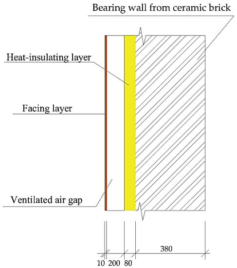
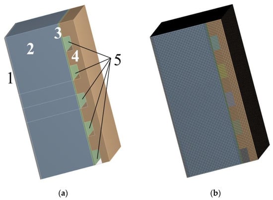
Figure 1.
multilayer wall enclosing structure with homogeneous bearing, heat-insulating layers and with closed and ventilated air gaps (the thickness of the layers of the structure is given in millimeters).
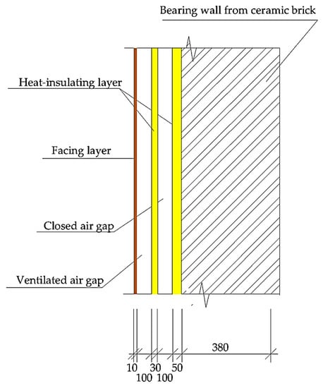
Figure 2.
multilayer wall enclosing structure with homogeneous bearing, heat-insulating layers and ventilated air gaps (the thickness of the layers of the structure is given in millimeters).
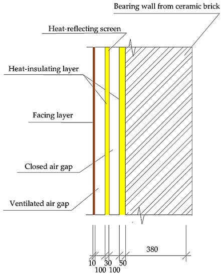
Figure 3.
multilayer wall enclosing structure with homogeneous bearing, heat-insulating layers and ventilated air gaps with a heat-reflecting screen-aluminum foil on the outer surface of a closed air gap (the thickness of the layers of the structure is given in millimeters).
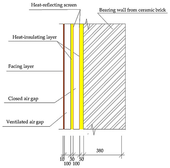
Figure 4.
multilayer wall enclosing structure with homogeneous bearing, heat-insulating layers and ventilated air gaps with a heat-reflecting screen-aluminum foil on the inner and outer surfaces of a closed air gap (the thickness of the layers of the structure is given in millimeters).
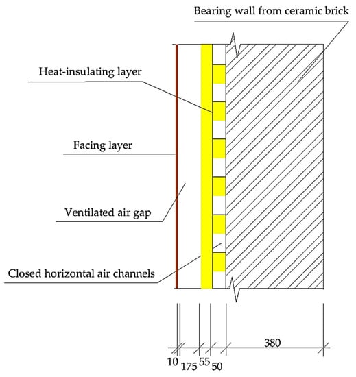
Figure 5.
multilayer wall enclosing structure with a homogeneous bearing layer and a heat-insulating plate layer with horizontal air channels (the thickness of the layers of the structure is given in millimeters).
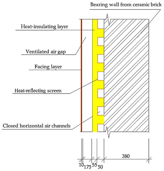
Figure 6.
multilayer wall enclosing structure with a homogeneous bearing layer and a heat-insulating plate layer with horizontal air channels and a heat-reflecting screen heat-reflecting screen— aluminum foil (the thickness of the layers of the structure is given in millimeters).
Table 4.
Climatic and internal boundary conditions [38].
Figure 1 shows a traditional enclosing structure with an air gap; the characteristics of its construction materials are presented in Table 1.
Figure 2, Figure 3, Figure 4, Figure 5 and Figure 6 show developed enclosing structures with an air gap; the characteristics of its construction materials are presented in Table 2 and Table 3.
The following assumptions are also made:
- The enclosure is painted in light color, and the coefficient of absorption of solar radiation by the material of the outer surface is 0.5.
- The height of the building is 18 m.
- To calculate the air parameters in the ventilated air gap, the parameters of “Granitogres” hinged facade with ceramic granite facade tiles 600 × 600 × 10 mm were used. The width of the supply slot is 10 mm. The sum of the coefficients of local resistance in this case is 5.4 [39].
At the second stage, to calculate the temperature fields in the enclosing structures, the finite element modeling method in the ANSYS environment was used. A finite element model of an enclosure section 1 × 1 m in size was built, in which the temperature field was calculated under given external conditions (Figure 7, Figure 8 and Figure 9). In this case, the finite element modeling of the ventilated facade was not performed, and the ventilated air gap effect was replaced by boundary conditions on the outer side of the enclosure without taking into account the ventilated facade. The task was divided into four stages, which were performed iteratively: (1) Calculation of the properties of the enclosure without taking into account the ventilated facade and with the properties of closed gaps and channels according to [40]; (2) Calculation of the air parameters in the ventilated facade; (3) Analysis of the temperature field in the enclosure, replacing the ventilated facade with boundary conditions; (4) Calculation of the properties of the closed gaps or channels.
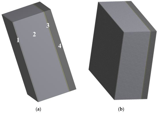
Figure 7.
The enclosure section according to Figure 1: (a) sketch: 1, 3—cement-sand plaster; 2—bearing layer from ceramic brick; 4—insulant from extruded polystyrene foam; (b) finite element model.
For the simplest case of an enclosing structure in the form of a multilayer wall with homogeneous layers, we will use the well-known equations of the thermal resistance of the structure (1), [41]:
where R—heat transfer resistance of multilayer enclosing structure, °C·m2/W; αint—heat transfer coefficient on the inner surface of the enclosing structure, W/(m2·°C); δi—thickness of the i-th layer, m; λi—coefficient of thermal conductivity of the material of the i-th layer, W/(m·°C); αext—heat-transfer coefficient on the outer surface of the enclosing structure, W/(m2·°C).
For all schemes of the enclosure, calculations of a stationary temperature field were carried out in the ANSYS environment under the following conditions:
- -
- ambient temperature—absolute minimum (−30.3 °C); average internal temperature was 20 °C;
- -
- ambient temperature—absolute maximum (44.2 °C); average internal temperature was 28 °C;
- -
- ambient temperature—the average temperature of the coldest five-day period with a probability of 0.92 (−14.3 °C); average internal temperature was 20 °C;
- -
- ambient temperature—the average temperature in April (13.5 °C); the average internal temperature was 20 °C.
The model shown in Figure 7b contains 81,120 and 20-node hexagonal finite elements with 342,221 nodes. The average quality of the model element is 0.9116.
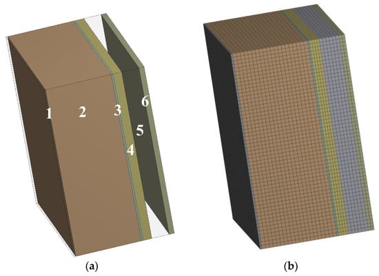
The model shown in Figure 8b contains 104,976 and 20-node hexagonal finite elements with 440,605 nodes. The average quality of the model element is 0.9283.
The model shown in Figure 9b contains 445,740 and 20-node hexagonal finite elements with 1,838,268 nodes. The average quality of the model element is 0.93949.
For each scheme, the average temperature value in the ventilated air gap was determined. This value was used when specifying the temperature boundary condition on the outer side of the enclosure without taking into account the ventilated gap. Subsequently, the iterative algorithm described in Section 2 was applied. For the enclosure Scheme 1, there was no need to use the iterative algorithm, since the enclosure did not contain closed air gaps [42].
3. Results and Discussion
This section presents an analysis of the temperature fields of a traditional enclosing structure with a ventilated gap and five proposed enclosing structures, where additionally closed gaps or horizontal channels are proposed as a novelty. At the same time, in some of the proposed developed enclosing structures, there is a heat-reflecting screen.
Below is the calculation of temperature fields for each design of the cladding.
Figure 10 and Table 5 show the calculation according to Scheme 1, which shows the temperature fields in the enclosure under various conditions.
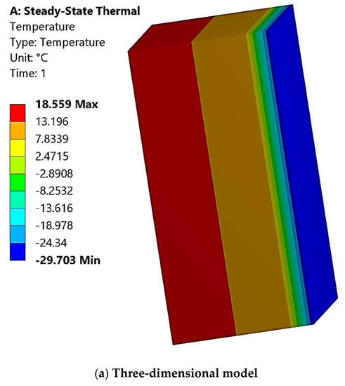
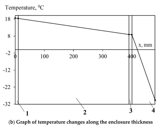
Figure 10.
Temperature field in the enclosure at the absolute minimum ambient temperature: (a) —three-dimensional model; (b) —graph of temperature changes along the enclosure thickness: 1, 3—cement-sand plaster; 2—bearing layer from ceramic brick; 4—insulant—extruded polystyrene foam.
Table 5.
Thermal resistance of the enclosure according to Figure 1.
The temperature fields in the enclosure at the maximum ambient temperature, at the average temperature of the coldest five-day period with a probability of 0.92 and at the average temperature of April were calculated by a similar method, the results of which are presented in Table 5.
Since the enclosure does not contain closed air gaps, the thermal resistance of the enclosure’s inner wall does not change depending on the conditions.
Figure 11 and Table 6 show the calculation according to Figure 2, which shows the temperature fields in the enclosure under various conditions.
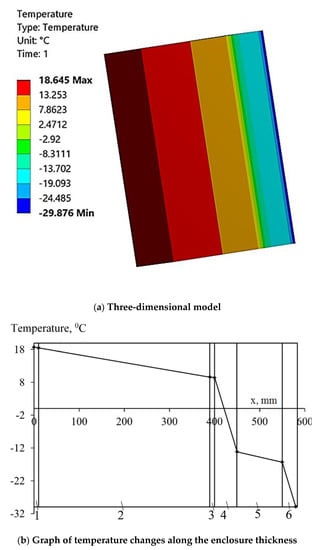
Figure 11.
Temperature field in the enclosure at the absolute minimum ambient temperature: (a) —three-dimensional model; (b) —graph of temperature changes along the enclosure thickness: 1, 3—cement-sand plaster; 2—bearing layer from ceramic brick; 4—insulant—extruded polystyrene foam; 5—closed air gap.
Table 6.
Thermal resistance of the enclosure according to Figure 2.
The temperature fields in the enclosure at the maximum ambient temperature, at the average temperature of the coldest five-day period with a probability of 0.92 and at the average temperature of April were calculated by a similar method, the results of which are presented in Table 6.
The thermal resistance of the enclosure’s inner wall varies depending on the boundary conditions. It can be seen that the thermal resistance of the gap at a negative temperature is higher than at a positive one.
Figure 12 and Table 7 show the calculation according to Figure 3, which shows the temperature fields in the enclosure under various conditions.
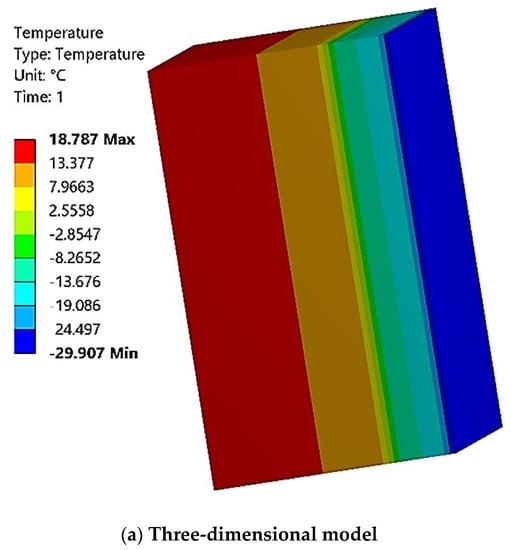

Figure 12.
Temperature field in the enclosure at the absolute minimum ambient temperature: (a) —three-dimensional model; (b) —graph of temperature changes along the enclosure thickness: 1, 3—cement-sand plaster; 2—bearing layer from ceramic brick; 4—insulant—extruded polystyrene foam; 5—closed air gap.
Table 7.
Thermal resistance of the enclosure according to Figure 3.
The temperature fields in the enclosure at the maximum ambient temperature, at the average temperature of the coldest five-day period with a probability of 0.92 and at the average temperature of April were calculated by a similar method, the results of which are presented in Table 7.
The thermal resistance of the enclosure’s inner wall varies greatly depending on the boundary conditions. The thermal resistance of the gap increases with a decrease in the difference between the internal and external temperatures. This is due to the fact that with a decrease in the temperature gradient, the intensity of heat transfer by radiation is greatly reduced. The addition of the reflecting screen allowed a significant increase of the thermal resistance of the closed gap (up to 3.5 times in the cold season).
Figure 13 and Table 8 show the calculation according to Figure 4, which shows the temperature fields in the enclosure under various conditions.
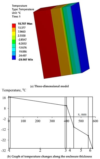
Figure 13.
Temperature field in the enclosure at the absolute minimum ambient temperature: (a) —three-dimensional model; (b) —graph of temperature changes along the enclosure thickness: 1, 3—cement-sand plaster; 2—bearing layer from ceramic brick; 4—insulant—extruded polystyrene foam; 5—closed air gap.
Table 8.
Thermal resistance of the enclosure according to Figure 4.
The temperature fields in the enclosure at the maximum ambient temperature, at the average temperature of the coldest five-day period with a probability of 0.92 and at the average temperature of April were calculated by a similar method, the results of which are presented in Table 8.
The thermal resistance of the enclosure’s inner wall varies greatly depending on the boundary conditions. The thermal resistance of the gap at a positive temperature is higher than at a negative one.
The addition of the second reflecting screen had little effect on the thermal resistance of the closed gap. Comparison of the calculation results with the enclosure Scheme 3 indicates that the thermal resistance of the air gap practically does not change under the conditions of the coldest five-day period with a probability of 0.92; at the average ambient temperature in April, the thermal resistance increases slightly when the second reflecting screen is added.
Figure 14 and Table 9 show the calculation according to Scheme 5, which shows the temperature fields in the enclosure under various conditions.
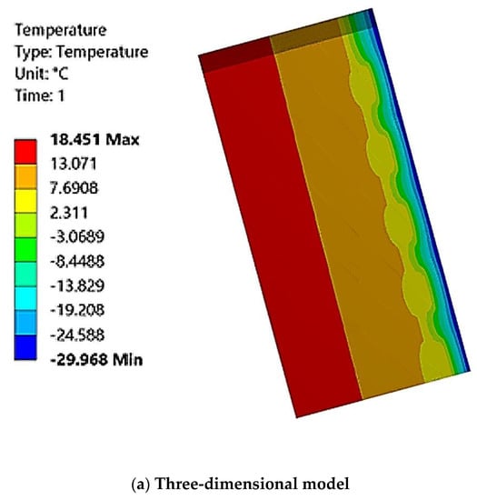
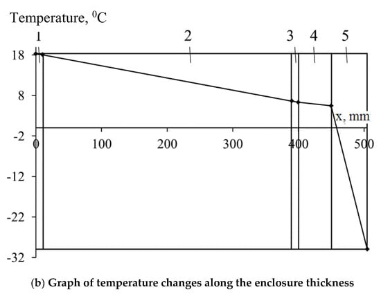
Figure 14.
Temperature field in the enclosure at the absolute minimum ambient temperature: (a) —three-dimensional model; (b) —graph of temperature changes along the enclosure thickness in the cross section of the air channel: 1, 3—cement-sand plaster; 2—bearing layer from ceramic brick; 4—closed air channel; 5—insulant—extruded polystyrene foam.
Table 9.
Thermal resistance of the enclosure according to Figure 5.
The temperature fields in the enclosure at the maximum ambient temperature, at the average temperature of the coldest five-day period with a probability of 0.92 and at the average temperature of April were calculated by a similar method, the results of which are presented in Table 9.
The thermal resistance of the closed air channel without the heat-reflecting coating is small and varies slightly depending on the temperature.
Figure 15 and Table 10 show the calculation according to the Figure 6, which shows the temperature fields in the enclosure under various conditions.
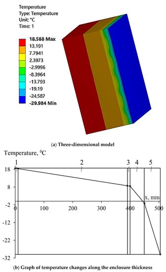
Figure 15.
Temperature field in the enclosure at the absolute minimum ambient temperature: (a) —three-dimensional model; (b) —graph of temperature changes along the enclosure thickness in the cross section of the air channel: 1, 3—cement-sand plaster; 2—bearing layer from ceramic brick; 4—closed air channel; 5—insulant—extruded polystyrene foam with heat — reflecting screen.
Table 10.
Thermal resistance of the enclosure according to Figure 6.
The temperature fields in the enclosure at the maximum ambient temperature, at the average temperature of the coldest five-day period with a probability of 0.92 and at the average temperature of April were calculated by a similar method, the results of which are presented in Table 10.
The heat-reflecting coating significantly (more than twice) increases the thermal resistance of the closed channel. The closed channel’s thermal resistance increases with a decrease in the difference between internal and external temperatures, with a sharp decrease in heat transfer by radiation.
The study compared the designs of energy-efficient enclosing structures with air gaps (Figure 2, Figure 3, Figure 4, Figure 5 and Figure 6) and the traditional constructive scheme (Figure 1). Traditional local building materials (Table 1, Table 2 and Table 3) and climatic conditions (Table 4) were used in the constructive solutions.
Temperature fields in enclosing structures were calculated using the method of finite element modeling and analysis in the ANSYS environment. In that, the finite element modeling of the ventilated facade was not carried out, and the ventilated air gap influence was replaced by the boundary conditions on the enclosure’s outer side, without taking into account the ventilated facade itself. The task of determining the thermal resistance of a non-ventilated gap was performed using the iteration method [43], the result of which is presented in Table 5, Table 6, Table 7, Table 8, Table 9 and Table 10 and Figure 10, Figure 11, Figure 12, Figure 13, Figure 14 and Figure 15.
The enclosing structure’s temperature fields analysis as a whole was carried out for the various external temperature values: the absolute maximum, the absolute minimum, the average temperature of the coldest five-day period with a probability of 0.92, and the average temperature of the first month after the end of the heating period (April).
According to Figure 10, Figure 11, Figure 12, Figure 13, Figure 14 and Figure 15, it was found that the thermal resistance of the enclosure according to Figure 2 in comparison with the traditional (Figure 1) enclosure at the minimum external temperature was higher by 6.1%, at the maximum temperature by 4.7%, at the average temperature of the coldest five days by 5.5%, and at the average temperature of the first month after the end of the heating period by 5.4%. This indicates the effectiveness of the developed constructive solution of the enclosure with air gaps in comparison with the traditional constructive scheme of the enclosure.
Comparison of the results of calculating the thermal resistance of the enclosing Figure 3 and Figure 4 with the heat-reflecting screens in comparison with the traditional (Figure 1) enclosures showed that the resistance is higher at the minimum external temperature by 16.7%, at the maximum temperature by 21%, at the average temperature of the coldest five-day period by 16.5%, and at the average temperature of the first month after the end of the heating period by 24.5%.
Comparison of the results of calculating the thermal resistance of the enclosing structures with the horizontal channels (Figure 5) with the traditional one (Figure 1) showed that at the minimum external temperature the resistance is lower by 8.5%, at the maximum temperature by 9.5%, at the average temperature of the coldest five-day period by 8.9%, and at the average temperature of the first month after the end of the heating period by 8.6%. However, the use of the heat-reflecting screen in the horizontal channels in Figure 6 in comparison with the traditional one (Figure 1) increases the thermal resistance at the minimum external temperature by almost 1%, at the maximum temperature by 4.1%, at the average temperature of the coldest five-day period by 1.5%, and at the average temperature of the first month after the end of the heating period by 8.4%.
The values obtained in the study for the thermal resistance of the external enclosing structures with the air channels are part of the comprehensive study of energy-efficient enclosing structures with adjustable and changing thermotechnical properties carried out by the authors. These data will be reviewed together with the results of the study of moisture and air conditions of claddings and air permeability properties of enclosures. As a result of the comprehensive analysis of the study, the most effective enclosing structure with the air gap will be selected.
4. Conclusions
As a result of the study, a comparison was made between traditional enclosing structures (Figure 1) and developed designs of energy-efficient claddings with air gaps (Figure 2, Figure 3, Figure 4, Figure 5 and Figure 6). Traditional local materials were used for the constructions of the claddings (Table 1, Table 2 and Table 3), and the climatic conditions were adopted according to [38], Table 4.
The finite element models of the temperature fields in the enclosure were constructed under various boundary conditions. The iterative computational scheme was used to determine the thermal resistance of the gap or the channel. However, the limitation of the proposed approach lies in the fact that it is premature to determine the effectiveness of the design based on the temperature fields’ analysis results. In this connection, it is necessary to carry out further studies of the developed structures (Figure 2, Figure 3, Figure 4, Figure 5 and Figure 6) in terms of the moisture conditions of the enclosure, the calculation of the air conditions, etc.
The study found that the thermal resistance of the enclosure according to Scheme 2 in comparison with the traditional (Figure 1) enclosure is higher at the minimum external temperature by 6.1%, at the maximum temperature by 4.7%, at the average temperature of the coldest five days by 5.5%, and at the average temperature of the first month after the end of the heating period by 5.4%. Comparison of the results of calculating the thermal resistance of the enclosing Figure 3 and Figure 4 with the heat-reflecting screens in comparison with the traditional (Figure 1) enclosures showed that the resistance is higher at the minimum external temperature by 16.7%, at the maximum temperature by 21%, at the average temperature of the coldest five-day period by 16, 5%, and at the average temperature of the first month after the end of the heating period by 24.5%. This indicates the effectiveness of the developed constructive solution of the enclosure with the air gaps in comparison with the traditional constructive scheme of the enclosure. It was also found that the use of the heat-reflecting screen on the inside or on both sides has little effect on the temperature fields in the enclosure layers.
Comparison of the thermal resistance of the enclosing structures with the horizontal channels (Figure 5) with that of the traditional one (Figure 1) showed that the resistance at the minimum external temperature is lower by 8.5%, at the maximum temperature by 9.5%, at the average temperature of the coldest five-day period by 8.9%, and at the average temperature of the first month after the end of the heating period by 8.6%, which indicates the inefficiency of Figure 5.
However, the use of the heat-reflecting screen in the horizontal channels according to Figure 6 in comparison with the traditional one (Figure 1) increases the thermal resistance at the minimum external temperature by almost 1%, at the maximum temperature by 4.1%, at the average temperature of the coldest five-day period by 1.5%, and at the average temperature of the first month after the end of the heating period by 8.4%, which indicates, on the contrary, the effectiveness of the application of Figure 6, taking into account the heat-reflecting screen.
Author Contributions
Conceptualization, N.Z., methodology, I.B. and A.T.; investigation, N.Z. and B.S.; data curation, I.B. and A.T.; writing—original draft preparation, N.Z. and B.S.; writing—review and editing, N.Z. and B.S.; supervision, I.B. and A.T.; project administration, N.Z. and B.S.; funding acquisition, N.Z., B.S., I.B. and A.T. All authors have read and agreed to the published version of the manuscript.
Funding
The study is funded by the authors of M. Auezov South Kazakhstan University.
Data Availability Statement
Data sharing is not applicable to this article.
Conflicts of Interest
The authors declare no conflict of interest.
Nomenclature
| a | Thickness [mm] |
| λ | Thermal conductivity coefficient [W/(m⋅°C)] |
| s | Heat absorption (within a period of 24 h) [W] |
| μ | Vapor permeability [mg/(m·h·Pa)] |
| ANSYS | Universal software system for finite element analysis |
| R | Heat transfer resistance of multilayer enclosing structure [°C·m2/W] |
| αint | Heat transfer coefficient on the inner surface of the enclosing structure [W/(m2·°C)] |
| δ | Thickness of the i-th layer [m] |
| λi | Coefficient of thermal conductivity of the material of the i-th layer [W/(m·°C)] |
| αext | Heat transfer coefficient on the outer surface of the enclosing structure [W/(m2·°C)] |
References
- Kurt, H. The usage of air gap in the composite wall for energy saving and air pollution. Env. Prog. Sus. Eng. 2010, 30, 450–458. [Google Scholar] [CrossRef]
- Demirbas, A. Energy balance, energy sources, energy policy, future developments and energy investments in Turkey. Eng. Conv. Manag. 2001, 42, 1239–1258. [Google Scholar] [CrossRef]
- Bolatturk, A. Determination of optimum insulation thickness for building walls with respect to various fuels and climate zones in Turkey. Ap. Ther. Eng. 2006, 26, 1301–1309. [Google Scholar] [CrossRef]
- Hasan, A. Optimizing insulation thickness for buildings using life cycle cost. Ap. Eng. 1999, 63, 115–124. Available online: https://ideas.repec.org/a/eee/appene/v63y1999i2p115-124.html (accessed on 27 December 2022). [CrossRef]
- DOE: 2011 Building Energy Data Book. Energy Efficiency and Renewable Energy; USA, Maryland, Department of Energy: 2011. Available online: https://ieer.org/wp/wp-content/uploads/2012/03/DOE-2011-Buildings-Energy-DataBook-BEDB.pdf (accessed on 25 December 2022).
- Kudabayev, R.; Suleimenov, U.; Ristavletov, R.; Kasimov, I.; Kambarov, M.; Zhangabay, N.; Abshenov, K. Modeling the Thermal Regime of a Room in a Building with a Thermal Energy Storage Envelope. Math. Model. Eng. Prob. 2022, 9, 351–358. [Google Scholar] [CrossRef]
- Kudabayev, R.; Mizamov, N.; Zhangabay, N.; Suleimenov, U.; Kostikov, A.; Vorontsova, A.; Buganova, S.; Umbitaliyev, A.; Kalshabekova, E.; Aldiyarov, Z. Construction of a model for an enclosing structure with a heat-accumulating material with phase transition taking into account the process of solar energy accumulation. East.-Eur. J. Enterp. Technol. 2022, 6, 26–37. [Google Scholar] [CrossRef]
- Malhotra, M. An Analysis of Maximum Residential Energy-Efficiency in Hot and Humid Climates. Master’s Thesis, Texas A&M University, College Station, TX, USA, 2005. Available online: https://www.semanticscholar.org/paper/An-Analysis-of-Maximum-Residential-Energy-in-Hot-Malhotra-Haberl/1c10d5c7f13324ee41cefadf1765b6d25b0b4e10 (accessed on 25 December 2022).
- Borodin, K.; Zhangabay, N.Z. Mechanical characteristics, as well as physical-and-chemical properties of the slag-filled concretes, and investigation of the predictive power of the metaheuristic approach. Curved Layer. Struct. 2019, 6, 236–244. [Google Scholar] [CrossRef]
- Soudian, S.; Berardi, U. Experimental performance evaluation of a climate-responsive ventilated building façade. J. Build. Eng. 2022, 61, 105233. [Google Scholar] [CrossRef]
- Dombaycı, O.A. The environmental impact of optimum insulation thickness for external walls of buildings. Build Env. 2007, 42, 3855–3859. [Google Scholar] [CrossRef]
- Kaynaklı, O. A study on residential heating energy requirement and optimum insulation thickness. Ren. Eng. 2008, 33, 1164–1172. [Google Scholar] [CrossRef]
- Ucar, A.; Balo, F. Effect of fuel type on the optimum thickness of selected insulation materials for the four different climatic regions of Turkey. Ap. Eng. 2009, 86, 730–736. [Google Scholar] [CrossRef]
- Soylemez, M.S.; Unsal, M. Optimum insulation thickness for refrigeration applications. Eng. Conv. Manag. 1999, 40, 13–21. [Google Scholar] [CrossRef]
- Horn, R.; Burr, M.; Fröhlich, D.; Gschwander, S.; Held, M.; Lindner, J.P.; Munz, G.; Nienborg, B.; Schossig, P. Life cycle assessment of innovative materials for thermal energy storage in buildings. Procedia CIRP 2018, 69, 206–211. [Google Scholar] [CrossRef]
- Comaklı, K.; Yuksel, B. Environmental impact of thermal insulation thickness in building. Ap. Ther. Eng. 2004, 24, 933–940. [Google Scholar] [CrossRef]
- Dombaycı, O.A.; Golcu, M.; Pancar, Y. Optimization of insulation thickness for external walls using different energy-sources. App. Eng. 2006, 83, 921–928. [Google Scholar] [CrossRef]
- Mohsen, M.S.; Akash, B.A. Some prospect of energy savings in buildings. Eng. Conv. Manag. 2001, 42, 1307–1315. Available online: https://aurak.ac.ae/publications/Some-prospects-of-energy-savings-in-buildings.pdf (accessed on 27 December 2022). [CrossRef]
- Zhangabay, N.; Abshenov, K.; Bakhbergen, S.; Zhakash, A.; Moldagaliyev, A. Evaluating the Effectiveness of Energy-Saving Retrofit Strategies for Residential Buildings. Int. Rev. Civ. Eng. 2022, 13, 118–126. [Google Scholar] [CrossRef]
- Al-Sallal, K.A. Comparison between polystyrene and fiberglass roof insulation in warm and cold climates. Ren. Eng. 2003, 28, 603–611. [Google Scholar] [CrossRef]
- CLEAR: Cavities and Air Space. Comfortable Low Energy Architecture. 2016. Available online: http://new-learn.info/packages/clear/thermal/buildings/building_fabric/elements/cavities_andair_spaces.html (accessed on 25 December 2022).
- CIT: Resistance of Air Layers and Surface Layers. Intelligent Energy Europe. Cork Institute of Technology. 2016. Available online: http://tea.ie/wpcontent/uploads/2011/09/Module-3.2-Resistance-of-air-layers-and-surface-layers.pdf (accessed on 5 March 2016).
- Pacific Northwest National Laboratory (PNNL). Oak Ridge National Laboratory: Building Technologies Program, Building America Best Practices Series, Vol. 17. In Energy Renovations: Insulation a Guide for Contractors to Share with Homeowners. PNNL-20972 May 2012.; 2012. Available online: https://www.pnnl.gov/main/publications/external/technical_reports/PNNL-20972.pdf (accessed on 25 December 2022).
- Mavromatidis, L.E.; Bykalyuk, A.; El Mankibi, M.; Michel, P.; Santamouris, M. Numerical estimation of air gaps’ influence on the insulating performance of multilayer thermal insulation. Build. Env. 2012, 49, 227–237. [Google Scholar] [CrossRef]
- Sadrzadehrafiei, S.; Mat, K.; Sopian, S.; Lim, C.H. Determining the cost saving and emission reduction of optimum insulation thickness and air gap for building walls. Aust. J. Basic Appl. Sci. 2011, 5, 2287–2294. Available online: file:///C:/Users/Admin/Downloads/Determining_the_Cost_Saving_and_Emission_Reduction.pdf (accessed on 28 December 2022).
- Alhefnawi, M.A.M.; Abdu-Allah Al-Qahtany, M. Thermal Insulation Efficiency of Unventilated Air-Gapped Facades in Hot Climate. Arab. J. Sc. Eng. 2016, 42, 1155–1160. [Google Scholar] [CrossRef]
- Abdullah, H.K.; Faraj, S.H. Experimental study for the effect of air gap in building walls on heat gain reduction. Mat. Today Proc. 2021, 61, 1043–1051. [Google Scholar] [CrossRef]
- Hamed, H.; David, W. Evaluation and use of airspaces for thermal resistance in buildings. J. Phys. Conf. Ser. 2021, 2069, 012098. [Google Scholar] [CrossRef]
- Ismaiel, M.; Chen, Y.; Cruz-Noguez, C.; Hagel, M. Thermal resistance of masonry walls: A literature review on influence factors, evaluation, and improvement. J. Build Phys. 2021, 4, 528–567. [Google Scholar] [CrossRef]
- Kvande, T.; Bakken, N.; Bergheim, E.; Thue, J.V. Durability of ETICS with Rendering in Norway—Experimental and Field Investigations. Buildings 2018, 8, 93. [Google Scholar] [CrossRef]
- Gullbrekken, L.; Kvande, T.; Jelle, B.P.; Time, B. Norwegian Pitched Roof Defects. Buildings 2016, 6, 24. [Google Scholar] [CrossRef]
- Asphaug, S.K.; Time, B.; Kvande, T. Moisture Accumulation in Building Façades Exposed to Accelerated Artificial Climatic Ageing—A Complementary Analysis to NT Build 495. Buildings 2021, 11, 568. [Google Scholar] [CrossRef]
- Bunkholt, N.S.; Säwén, T.; Stockhaus, M.; Kvande, T.; Gullbrekken, L.; Wahlgren, P.; Lohne, J. Experimental Study of Thermal Buoyancy in the Cavity of Ventilated Roofs. Buildings 2020, 10, 8. [Google Scholar] [CrossRef]
- Gullbrekken, L.; Uvsløkk, S.; Geving, S.; Kvande, T. Local Loss Coefficients inside Air Cavity of Ventilated Pitched Roofs. J. Build. Phys. 2018, 42, 197–219. [Google Scholar] [CrossRef]
- Ingebretsen, A.B.; Andenæs, E.; Kvande, T. Microclimate of Air Cavities in Ventilated Roof and Façade Systems in Nordic Climates. Buildings 2022, 12, 683. [Google Scholar] [CrossRef]
- Code of Rules of the Republic of Kazakhstan 2.04-107-2013 Building Heat Engineering: State Standards in the Field of Ar-chitecture, Urban Planning and Construction. Code of Rules of the Republic of Kazakhstan.—JSC “KazNIISA”, LLP “Astana Stroy-Consulting”, 2013. Approved and Enacted on 1 July 2015. 80p. Available online: https://online.zakon.kz/m/document/?doc_id=37599018 (accessed on 28 December 2022).
- Isachenko, V.P.; Osipova, V.A.; Sukomel, A.S. Heat transfer. In Textbook for Universities, 3rd ed.; Reprint. and Additional—Moscow.: “Energy”; 1975. Volume 488. Available online: https://djvu.online/file/V5R73pysiRdmX (accessed on 2 January 2023).
- Code of Rules of the Republic of Kazakhstan 2.04-01-2017 Building Climatology: State Standards in the Field of Architecture, Urban Planning and Construction. Code of Rules of the Republic of Kazakhstan.—JSC “KazNIISA”, LLP “Astana Stroy-Consulting”, 2017. Approved and Enacted on 20 December 2017. 43p. Available online: https://online.zakon.kz/m/document/?doc_id=37599018 (accessed on 28 December 2022).
- Nikolatev, S.; Granik, U. Recommendations for the Design of Hinged Facade Systems with a Ventilated Air Gap for New Construction and Reconstruction of Buildings; Moskomarchitectura: Moscow, Russia, 2002; p. 159. Available online: https://files.stroyinf.ru/Data1/9/9931/ (accessed on 28 December 2022).
- ANSYS Learning—Thermal Convection in Heat Transfer. Available online: https://courses.ansys.com/index.php/courses/thermal-convection-in-heat-transfer/ (accessed on 28 December 2022).
- Malyarenko, V.A. Technical Thermophysics of Enclosing Structures of Buildings and Structures/ V.A. Malyarenko. Textbook; KHNAGH: Kharkiv, Ukraine, 2001; p. 280. Available online: https://www.studmed.ru/malyarenko-va-redko-af-i-drtehnicheskaya-teplofizika-ograzhdayuschih-konstrukciy-zdaniy-i-sooruzheniy_c9492939c3e.html (accessed on 2 January 2023).
- Umnyakova, N.P. Thermal protection of closed air gaps with reflecting thermal insulation. Zhilishchnoe Stroit. 2014, 2, 16–20. Available online: https://cyberleninka.ru/article/n/teplozaschita-zamknutyh-vozdushnyh-prosloek-s-otrazhatelnoyteploizolyatsiey (accessed on 28 December 2022).
- Gagarin, V.G. About some thermotechnical mistakes made when designing ventilated facades. ABOK 2005, 2, 52–60. Available online: https://www.abok.ru/for_spec/articles.php?nid=2785 (accessed on 28 December 2022).


Disclaimer/Publisher’s Note: The statements, opinions and data contained in all publications are solely those of the individual author(s) and contributor(s) and not of MDPI and/or the editor(s). MDPI and/or the editor(s) disclaim responsibility for any injury to people or property resulting from any ideas, methods, instructions or products referred to in the content. |
© 2023 by the authors. Licensee MDPI, Basel, Switzerland. This article is an open access article distributed under the terms and conditions of the Creative Commons Attribution (CC BY) license (https://creativecommons.org/licenses/by/4.0/).