1. Introduction
Columns should be treated with special care in building design, as their capacity is vital when considering potential progressive collapse of the structural frame. Column resistance is most likely to be affected by instability phenomena. The buckling of axially loaded columns is a substantial subtask within the overall set of column stability issues. Studies of steel column stability at ambient temperatures have been thoroughly reported. In recent years, considerable efforts in structural engineering research have been made to address fire conditions. Compared to ambient conditions, the structural behaviour of steel columns at elevated temperatures becomes more complex due to the temperature-dependent stress–strain relationship of the material. Numerical methods have been proven to produce reliable results in various tasks for structural behaviour in fire. For practical design purposes, a relevant Eurocode [
1] procedure is available, initially proposed by Franssen [
2]. The current Eurocode method related to the buckling capacity of columns in fire is based on extensive experimental [
2] and numerical investigations [
3]. Certain discrepancies between the Eurocode EN 1993-1-2 [
1] method and the results of experimental work, as well as numerical modelling, have been reported by different authors. Knobloch et al. [
4] and Somaini et al. [
5] point out that the simplified design approach, although convenient for use, does not properly account for material nonlinearity at elevated temperatures. Reduced accuracy may also be caused by the extrapolation of the hot-rolled H-section data to other various profiles, such as hollow sections, as concluded by Vila Real et al. [
6]. Several authors, such as Somaini et al. [
5], Toh et al. [
7] and Kervalishvili and Talvik [
8], have pointed out that, in certain parameter ranges, the Eurocode design results may appear nonconservative.
In recent years, along with the development of computational capacity and relevant methods, the probabilistic design approach has been introduced as an alternative procedure to address the safety level and reliability of structures, especially in performance-based design methodology [
9]. Relevant research reports deal with different structural elements, and the reliability of compression elements has been studied at normal temperatures and in fire conditions [
10,
11,
12,
13]. A reliability-based approach has been used to account for uncertainties in order to achieve the optimised solution of structures of inherently nonlinear character [
14]. Evaluating the safety of structures with probabilistic methods in various limit states requires the intensive analysis of structural models. A high number of repeated samples of the model with random input values accounting for uncertainties is necessary for the commonly used Monte Carlo simulation method. There is a similar need for a high number of repeated calculations applied to emerging data-based techniques of structural assessment [
15]. Although the finite element method (FEM) has been widely used and approved as a sufficiently accurate method to reproduce the behaviour of structures under extreme damage effects, such as fire, its use for the adequate number of iterations in probabilistic methods appears to be costly in terms of time and may be impractical to apply [
9,
16]. Various simplifying methods are not always sufficiently accurate or convenient to use [
12,
16]. Consequently, there is a growing need for methods that provide both adequate accuracy and computational efficiency for structural analysis in fire.
In the present work, a computationally efficient capacity verification method for axially loaded steel columns with rectangular hollow section (RHS) and square hollow section (SHS) with section classes 1 and 2 (as defined in [
1]) in fire conditions is proposed. Numerical modelling is conducted to verify the accuracy of the method compared to EN 1993-1-2 based results. Computational efficiency of the method is assessed by comparison with the finite element model. The reported analytical procedure is derived on the basis of nonlinear material model. In this way, the stiffness properties can be regarded in detail and it is possible to incorporate different materials in the same framework. The format of the proposed technique is specifically suitable for reliability analysis as the relevant parameters with uncertainties can be explicitly handled in the procedure.
2. Alternative Methods for Column Buckling in Fire
The EN 1993-1-2 [
1] design method for axially loaded columns in fire conditions is, in principle, a modified version of the method for similar problems in ambient temperature conditions, which is based on first-yield criterion [
17]. The criterion was introduced by Ayrton and Perry [
18] as follows: an initially curved column loses stability when maximum compression stresses on the concave side in the mid-height section of the column approach the yield limit value. EN 1993-1-2 uses the Ayrton–Perry framework for buckling capacity estimation of axially loaded elements, which is modified to fit the model to the experimental results [
2], and extensive numerical investigation by Talamona et al. [
3], as presented by Schleich et al. [
19].
An alternative approach based on a Rankine-type solution was proposed by Toh et al. [
7] and Maślak [
20]. The solution is presented in compact analytical form and the predicted buckling capacity is close to the result predicted by the EN 1993-1-2 method. Capacity estimation of a restrained steel column in fire conditions was proposed by Neves et al. [
21] and Wang et al. [
22]. Von Karman type method for steel column buckling in fire was presented by Somaini [
5]. The method proposed in this work is also based on the Von Karman solution.
The Von Karman method focuses on the equilibrium between the external bending moment and the internal bending moment in the critical section [
23]. The initial imperfect shape of a column is approximated by a sinusoidal curve (
Figure 1, Equation (1)); the amplitude is denoted as
y0.mid. Lateral displacement (Equation (2)) develops with the increasing axial load
Ne, and the eccentricity of the axial load increases from
y0.mid to
ytot.mid =
y0.mid +
y1.mid, where
y0.mid and
y1.mid are shown in
Figure 1. This process obviously leads to an increase in the bending moment, as shown in Equation (3). The column remains stable until the increase in the external bending moment
Me is fully compensated by the increase in the internal bending moment
Mi and the load
Ne is equal to the internal force
Ni. Stability criteria can be formulated as Equation (4). Generally, the internal bending moment
Mi and the internal axial force
Ni are interconnected. Section curvature
χ links
Mi and
ytot.mid. For a column with pinned ends, the mid-height section curvature and the maximum lateral deflection are linked with Equations (5) and (6), where
ε1 and
ε2 are the strains at the section extreme points and
h is the section height. If the strains are available, the internal forces of the section can be calculated for elastic state, but it is not the case for steel in fire conditions. Using Equations (4)–(6), and using the dependences of
Mi and
Ni on the strains
ε1 and
ε2, it is possible to define the buckling load limit of a column. Due to the complicated nature of the steel material law in fire conditions, the analytical model for Equation (4) is not so easy to establish. The Von Karman method can be effectively used in the numerical procedure with section discretisation, but computational efficiency of the method does not outperform finite element formulation.
3. Numerical Modelling
The finite element method (FEM) is widely used for analysing the buckling phenomenon of steel structures in fire conditions. The design method proposed in this work also utilises the simulation results of a nonlinear FEM model. Aspects of numerical modelling of the problem under consideration are well known. Therefore, only a short summary of the modelling is presented herein and more details can be found in [
8]. The model consisted of 20 non-linear beam elements along the column axis. Section meshing was used to calculate the section stiffness and internal forces. Temperature-dependent material models (thermal elongation and stress–strain relationships) from EN 1993-1-2 [
1] were implemented. Initial curvature was taken as a half sinusoidal wave in accordance with [
24]. The influence of residual stresses was considered in accordance with [
24].
The program of numerical studies consisted of six sections (
Table 1). Fifteen slenderness (see Equation (7)) values were selected to model the columns in eight temperature ranges. Steel grades S235, S355 and S460 were used for all specimens. The total number of analysed FEM models was 2160.
The results of the numerical simulations are reported here in brief. Firstly, the difference between the buckling factors of different section profiles is addressed.
Table 2 presents the results of statistical analysis comparing the buckling factors for individual sections
χi with the mean for the whole set of sections
χgr.mean (factor
χi/
χgr.mean). It is obvious that the responses of columns with different section profiles are rather similar. Buckling factors obtained by the FEM (
χFEM) and the EN 1993-1-2 methods (
χEC) are compared in
Figure 2. Deviations between the non-linear FEM and EN 1993-1-2 results can be observed and are in line with similar results reported earlier in [
4,
6,
8].
Stresses at the limit load at the characteristic section points along the column axis are presented in
Figure 3. Point 1 is located at the outer edge of the section on the side of the column, where lateral deflection causes tension; Point 2 is located at the outer edge of the section on the side of the column, where lateral deflection causes compression; and Point C is located at the centre of gravity of the section. The stresses are presented in relation to the proportionality limit for the respective temperature. Three slenderness values and three temperatures were addressed. It is evident that the stress state at failure varies with both temperature and slenderness: for a low slenderness value (
λ20°C = 0.1) and for all temperatures, the stresses in the column at failure are above the proportionality limit; for a high slenderness value (
λ20°C = 2.0) and for temperatures
θ = 200 °C and
θ = 500 °C, buckling took place when the maximum stresses approached the proportionality limit (first-yield criterion); while for
θ = 900 °C, buckling takes place elastically; with a moderate slenderness value (
λ20°C = 1.0), buckling took place when the section was partially in a plastic state, and the extent of plastification varied with temperature.
The path of strains at Points 1, 2 and C of the mid-height section is presented in
Figure 4. With increasing the axial load, the strains start to diverge intensively when approaching the buckling load. It is worth noting that, at Point 1 of the section, the unloading only took place in the very vicinity of the buckling occurrence.
The method proposed in this work was based on and validated by the results obtained by FEM. Results obtained by FEM were validated by the test results of ETHZ [
25].
Tests in ETHZ [
25] were performed in 2012 on a limited number of columns, including I-sections with buckling about the weak and strong axes and RHS sections. Tests were organised in the load domain, i.e., columns were heated uniformly up to a given temperature and then loaded until collapse. The tests were accompanied by material tests and accurate data regarding stress–strain relationships, which are very important for the validation of the numerical model. The validation results are presented in
Figure 5 and
Table 3. In
Table 3, the following notation is used: ID is the test identifier in the ETHZ [
25] test report;
fy is the actual yield limit stress in ambient conditions;
Fult is the ultimate load;
σc is the stress from the axial load;
fy.fi is the yield limit stress corresponding to the temperature at failure calculated in accordance with EN 1993-1-2 [
1];
χtest is the buckling factor according to the test result;
χFEM is the buckling factor calculated by FEM; and
θtest is the average temperature at failure according to the test results. By analysing the results of the validation, it can be concluded that good correlations with the ETHZ [
25] test were achieved.
4. Proposed Design Method
The proposed method is based on the Von Karman solution described in
Section 2.
In the case of an axially loaded column with pinned supports and sinusoidal initial shape, it is sufficient if the condition described by Equation (4) is checked only in the mid-section of the column, where the maximum lateral displacement occurs. The relationship between the lateral displacement and the mid-section curvature is established by Equation (5). In fire conditions, the stress distribution across the section is not linear and the calculation of the internal forces is a complex task. Destabilising forces can be expressed as Equation (3).
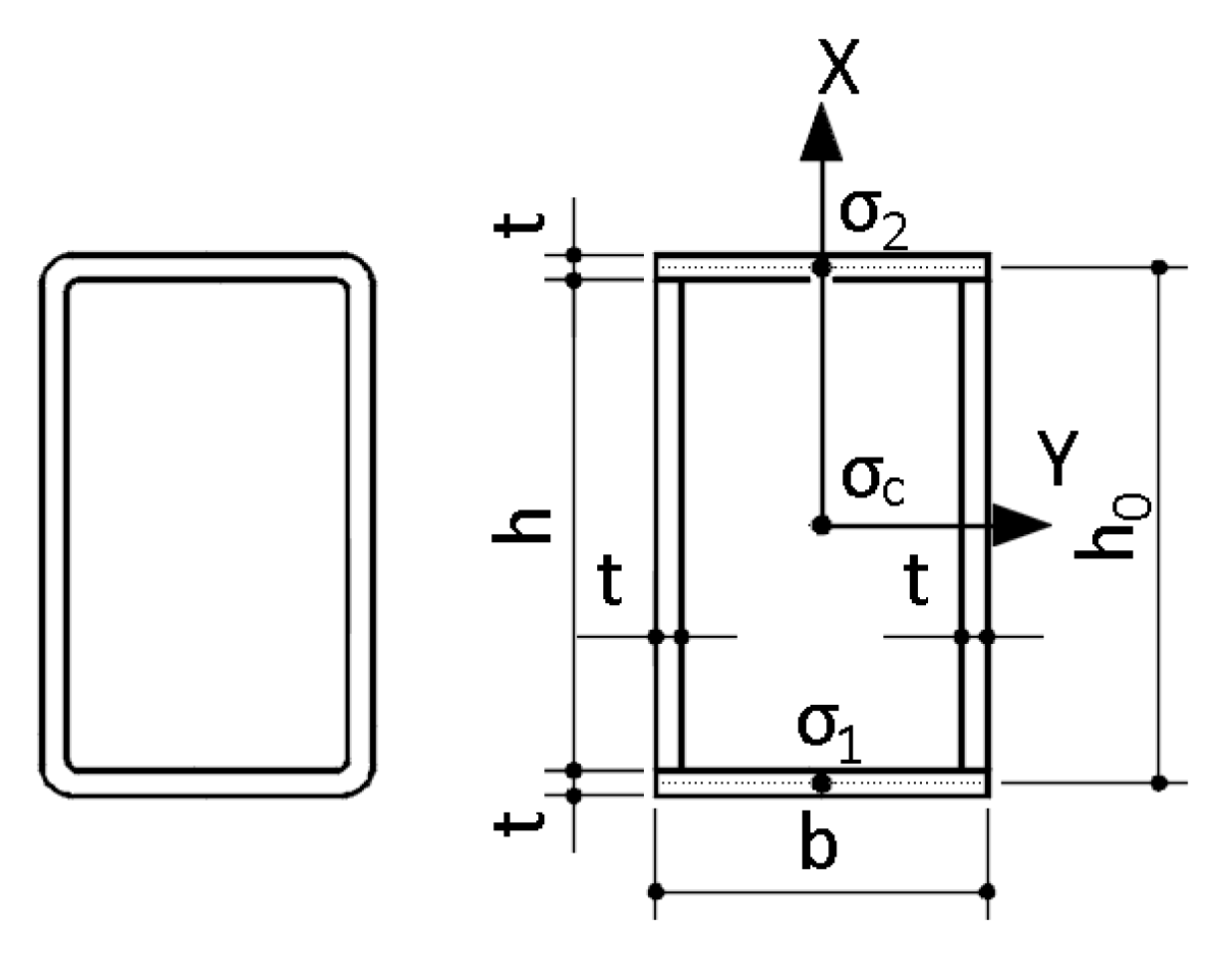
The mid-section of the column under consideration is presented in
Figure 6. The following initial assumptions are made:
the Navier–Bernoulli (plane sections) hypothesis is valid;
the Eurocode [
1] material model is valid;
Point 1 is subjected to additional compression as a result of the lateral displacement, and, in contrast, Point 2 is subjected to unloading as a result of the lateral displacement.
The following description of the formulation is rather simple in essence, but is relatively lengthy and may seem burdensome. The authors are aware of such a risk, but it is provided for the sake of completeness of the method presentation.
The internal forces of the section are defined as follows. An assumption is made as indicated in Equation (8): linear stress variation across the section is assumed, which automatically means that the stress
σc at the centroid is equal to the mean value of stresses at Points 1 and 2 presented in (8). The internal axial force
Ni is split into components as shown in Equation (9): force in the flanges, according to Equations (10) and (11), and force in the wall according to Equation (12).
The Simpson integration scheme was used for the section wall. Total internal axial force is given in Equation (13):
Factors
α1 and
α2 are introduced as Equations (14) and (15).
The internal bending moment is formulated in Equations (16)–(19).
Factor
β is introduced as Equation (20):
The internal bending moment can then be rewritten as Equation (21):
The stress at Point 1 is expressed through the stress at Point 2, assuming the internal force (
Ni) and the external axial forces (
Ne) are in equilibrium (Equation (22)). It is assumed that stresses at Point 1 follow the Eurocode [
1] material model. Then, Equation (22) can be rewritten as Equation (23):
In Equation (23), and further following the EN 1993-1-2 [
1] material model, the following notations are used:
fp.θ—proportionality limit stress at temperature
θ;
εy.θ—yield strain;
aEC,
bEC and
cEC—identical to the parameters
a,
b and
c of the EN 1993-1-2 [
1] material model. For a pin-ended column with sinusoidal initial curvature, the total lateral displacement at the mid-height can be expressed as a function of the section curvature—Equation (24):
Parameter
is introduced as Equation (25) for convenience.
The external bending moment
Me is expressed in Equation (26). Dependency of the stress at Point 2 and the strain at Point 2 on the strain at Point 1 is established in Equation (27):
The relation between the stress at Point 2
σ2 and the secant modulus
Es.fi is approximated as in Equation (28):
Es.fi is formulated as Equations (29) and (30):
In case the stress from the axial load only is lower than the proportionality limit, the secant modulus is equal to the elasticity modulus for the temperature under consideration (
), as defined in Equation (29); in case the opposite is true, the secant modulus is calculated using Equation (30), where
εfi is simply an inverse function to the EN 1993-1-2 [
1] stress function in the inelastic range. Equation (23) can be rewritten into Equation (31):
Equation (28) is inserted into Equation (27), producing Equation (32), which is the dependence of the strain at Point 2 on the strain at Point 1:
Factors
ϒ0–
ϒ8 are used for convenience according to Equations (33)–(42):
Equation (32) is re-introduced as Equation (43):
Equation (43) is inserted into Equation (31), which, after transformation, results in a quadratic equation in relation to
ε1 in Equation (44):
The discriminant of Equation (44) is equal to Equation (45), and the roots can be found using (46). Equation (44) can have non-complex roots only if the discriminant (45) is non-negative:
Equation (45) can be used to check the buckling condition: if Equation (45) is positive, stability is guaranteed; buckling load limit is obtained when Equation (45) is equal to 0. Equation (45) can be rewritten using Equations (40)–(42), obtaining Equation (47), which is a simple quadratic equation in relation to
ϒ4:
The discriminant of Equation (47) is given by Equation (48), and the root with physical meaning is defined in Equation (49):
By equating Equations (38) and (49) and performing some transformations, it is possible to obtain Equation (50):
A direct solution of Equation (50) with reasonable effort is not possible, as
Es.fi and
ϒ0 are both functions of
Ne. Critical force is introduced as Equation (51) and the stability criteria is presented as Equation (52):
The proposed method is based on a section shape consisting of rectangles (
Figure 6). The actual section may deviate from the idealised area (e.g., chamfered corners of the SHS profiles). The idealised section area is denoted by
Ai, while the actual section area is denoted by
A. In case the design load is denoted by
Nfi,
Ne is defined as Equation (53):
Performance of the proposed method against non-linear FEM is demonstrated in
Figure 7. The maximum limit buckling load
Ncr.fi.max was obtained numerically using Equation (51), satisfying condition in Equation (52). The buckling factor
χfi was derived using Equation (54):
In
Figure 7, the buckling factor
χfi is compared to the buckling factor obtained by FEM
χFEM. Performance was satisfactory for small-to-moderate initial imperfection values:
y0 =
L/1000 −
L/500. The performance of the method for a relatively large initial imperfection of
y0 =
L/250 was judged to be unsatisfactory. According to the accepted approach, the initial imperfection of
y0 =
L/1000 is used for buckling problems in fire conditions [
24]. As the proposed model is intended to be used in reliability analysis where initial imperfection is one of the important parameters, the method was improved by introducing a fitting procedure. It was assumed that the main reason why the proposed method diverged from the non-linear FEM is the assumption of linear stress variation, as shown in Equation (8). The assumption was modified as follows: the factors
α1 and
α2 (Equations (14) and (15)) were redefined as Equations (55) and (56), where parameter
g was introduced as a function of initial imperfection and slenderness:
Parameter
u was defined as Equation (57):
The buckling capacity model with redefined
α1 and
α2 was fitted to a non-linear simulation data array. The non-linear FEM data array was formed from the results for temperature range
θ = 200–900 °C, the slenderness range
λ20°C = 0.1–2.0, the yield limit range 235–460 MPa and the initial imperfection range
L/
y0 = 250–1000. The results of the fitting procedure were compiled into Equations (58)–(62):
The performance of the updated model is demonstrated in
Figure 8. The performance of the updated model against FEM was good. Therefore, the proposed method can be evaluated against EN 1993-1-2 [
1] on the basis of
Figure 2, where FEM and EN 1993-1-2 are compared. It is concluded that the proposed method provides improved accuracy compared to EN 1993-1-2.
As the proposed method has no direct analytical solution, the buckling capacity can be checked using one calculation cycle, but an iterative procedure is needed to define the buckling capacity limit. A simple line search algorithm can be used for this purpose. The buckling capacity model as shown in Equation (51) can be effectively used for reliability calculations using a Monte Carlo simulation, as the precise value of the capacity is not necessary and binary (0/1) type output is sufficient [
26].
The calculation of the maximum buckling capacity limit by the proposed method was computationally efficient, demanding, on average, 2 × 10⁻⁵ s compared to the 2 s time for non-linear FEM procedure (8 cores 3.6 GHz). The computation time for the capacity verification was even shorter, approaching 10−6 s.
The procedure of the proposed method is summarised as follows:
Calculate the parameter u using Equation (57);
Calculate the parameters p1, p2, p3, q1 and q2 using Equations (59)–(62);
Calculate the parameter g using Equation (58);
Calculate the parameters α1 and α2 using Equations (55) and (56);
Calculate the parameter β using Equation (20);
Calculate the secant modulus Es.fi using Equations (29) or (30) as:
- 7.
Calculate the model parameters χ0 and γ0 using Equations (25) and (33);
- 8.
Calculate the EN 1993-1-2 [
1] material model parameters
aEC,
bEC and
cEC;
- 9.
Calculate the critical force using Equation (52) as:
- 10.
Check the buckling capacity:
5. Example
In order to demonstrate the proposed method, a calculation example is presented.
Section: SHS200 × 6.0
Steel grade: S355 -> fy = 355 MPa, E = 210,000 MPa
Temperature: θ = 500 °C
Effective length: Leff = 3010 mm -> λ20°C = 0.5
Section parameters: A = 4560 mm2, Iy = 2.83 × 107 mm4
Axial load: Nfi = 720 kN
Initial imperfection: y0 = 6.0 mm
ky,θ = 0.780, kp,θ = 0.360, kE,θ = 0.600, εp,θ = 0.0010143, εy,θ = 0.02, fy,θ = 276.9 MPa
fp,θ = 127.8 MPa,
Ea,θ = 126,000 MPa
Eurocode method:
Notation from EN 1993-1-2 [
1] is used.
FEM:
Buckling resistance obtained by the FEM procedure described in
Section 3.
Proposed method:
Section geometrical parameters from
Figure 6:
Calculate the parameter
u using Equation (57):
Calculate the parameters
p1,
p2,
p3,
q1 and
q2 using Equations (59)–(62):
Calculate the parameter
g using Equation (59):
Calculate the parameters
α1 and
α2 using Equations (55) and (56):
Calculate the parameter
β using Equation (20):
Calculate the EN 1993-1-2 [
1] material model parameters
aEC,
bEC and
cEC:
Calculate the secant modulus
Es.fi using Equations (29) or (30):
Calculate the model parameters
χ0 and
γ0 using Equations (25) and (33):
Calculate the critical force using Equation (51):
Check the buckling capacity:
The presented method enables us to check the buckling capacity with the given axial force. As the critical force Ncr.fi itself is dependent on the axial force Ne, the maximum buckling capacity Ncr.fi.max can be calculated iteratively or by increasing stepwise the axial load Ne until Ne = Ncr.fi. In this example, the maximum buckling capacity calculated using the proposed method is Ncr.fi.max = 724,610 N, which is very close to the buckling capacity calculated using nonlinear FEM, Nfi.FEM = 736,260 N (the difference is 1.6%).


