
Study on Polypropylene Twisted Bundle Fiber Reinforced Lightweight Foamed Concrete

 ,
,  , ,
, ,  ,
,  and
and 
Abstract
:1. Introduction
2. Materials and Methods
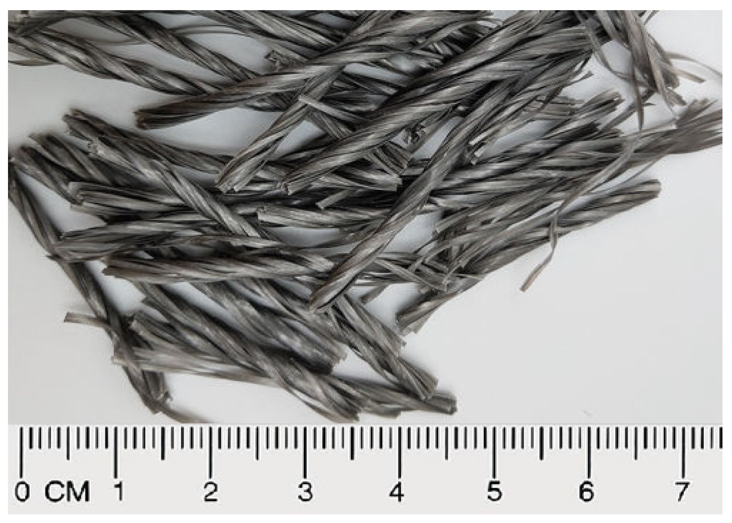
2.1. Materials
2.2. LFC Mix Design
2.3. LFC Preparation
- (1)
- The foaming agent composed of protein was diluted with water at a ratio of 1:34. Using a high-pressure pump, the dilution was introduced into the foamer’s bucket. The dilution was put in the foaming apparatus and exposed to high-pressure air generated by an air compressor in order to create homogenous fine bubbles.
- (2)
- Cement, fine sand, PTBF, and water were placed into the concrete mixer and mixed for approximately 3 min. The relative viscosity of each fresh LFC was measured immediately after mixing. An appropriate amount of foam (Figure 2a) was subsequently introduced into the mortar slurry and mixed for another 3 min until a well-blended slurry and homogenous mix was produced (Figure 2b).
- (3)
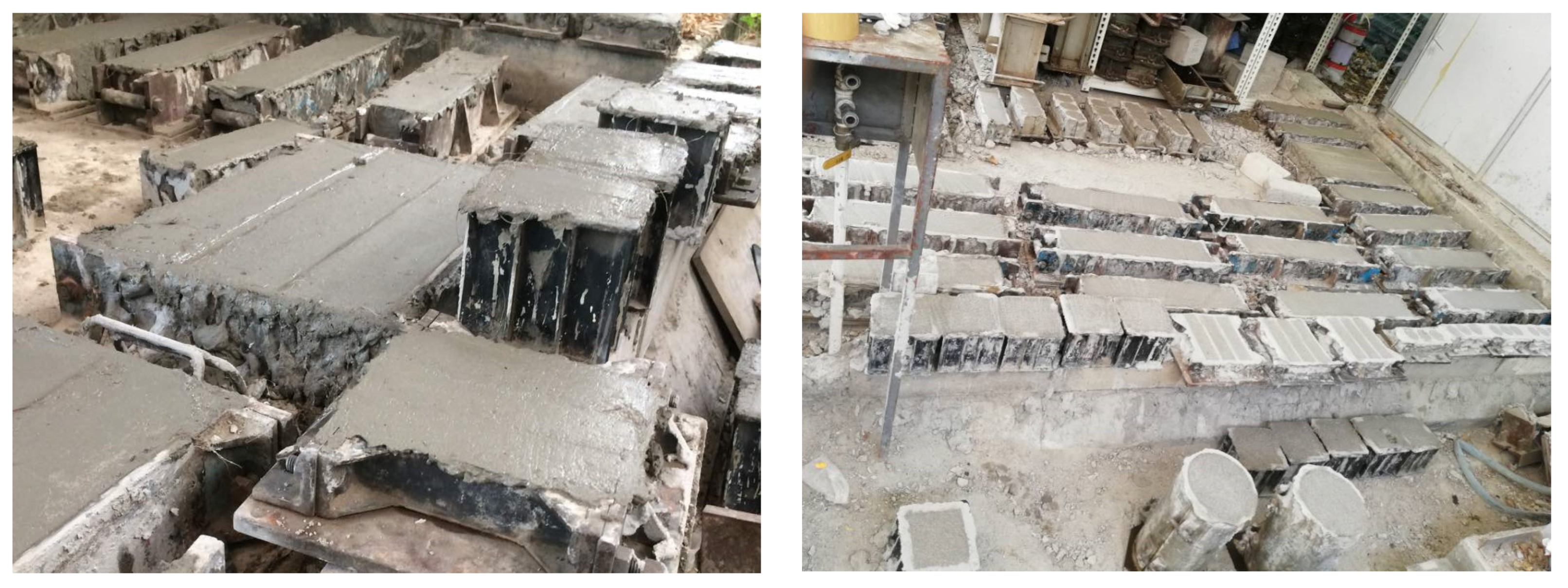
- The LFC slurry was then poured into molds (cube, prism, and cylinder), leveled with a steel ruler, and then placed in a room at 20 ± 5 °C with relative humidity (RH) of 60% as shown in Figure 3. The specimens were removed from the molds after 24 h and stored in a fog room (20 ± 2 °C; RH > 95%) for curing purposes.
2.4. Details of Experimental Tests
2.4.1. Compression Test
2.4.2. Flexural Test
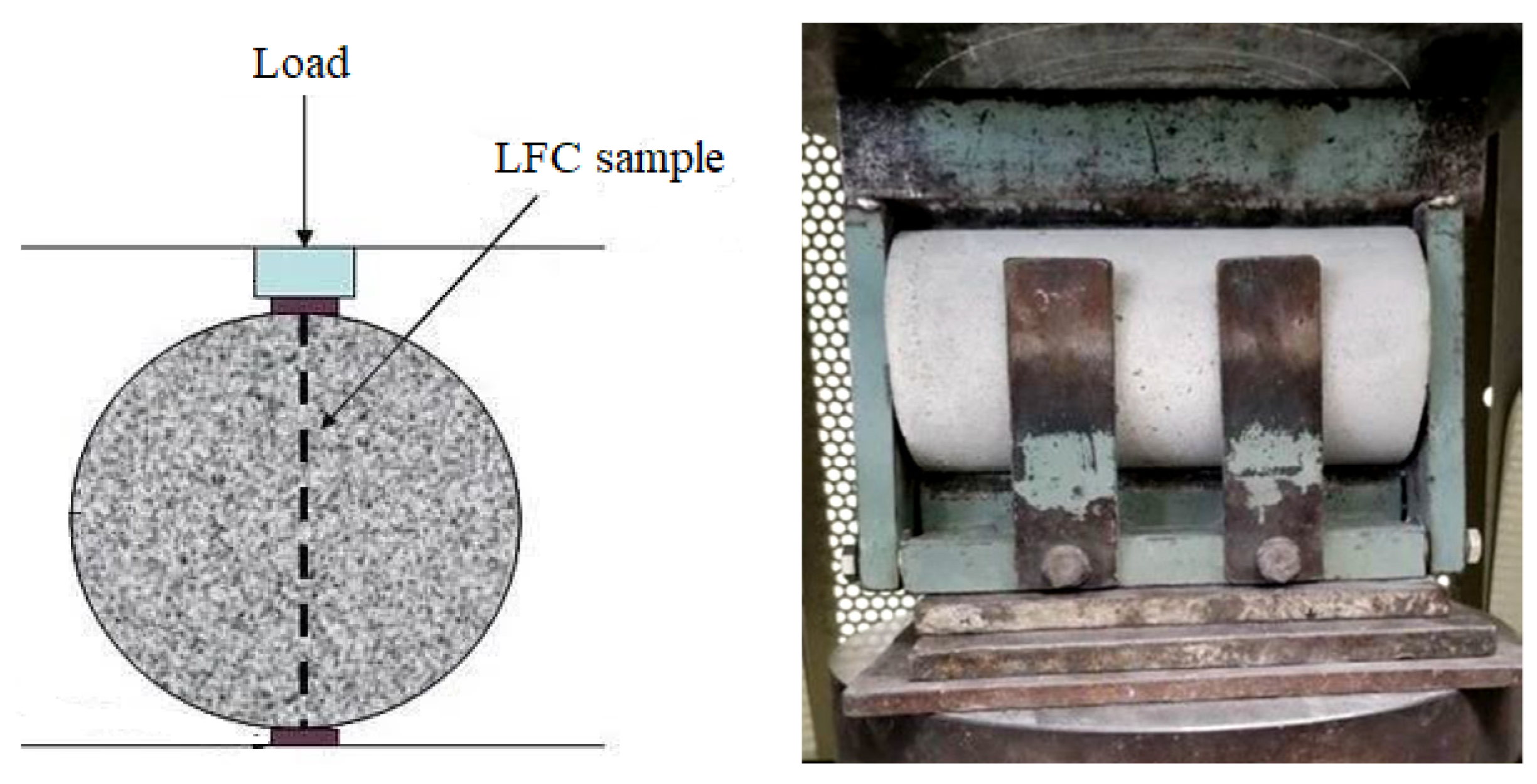
2.4.3. Splitting Tensile Test
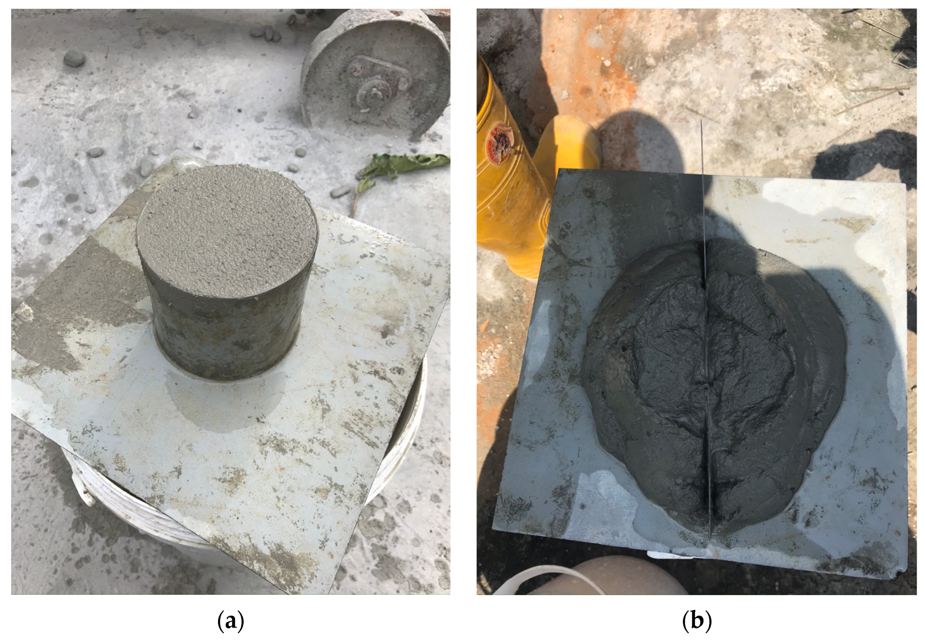
2.4.4. Flow Table Test
2.4.5. Porosity Test
2.4.6. Water Absorption Test
3. Results
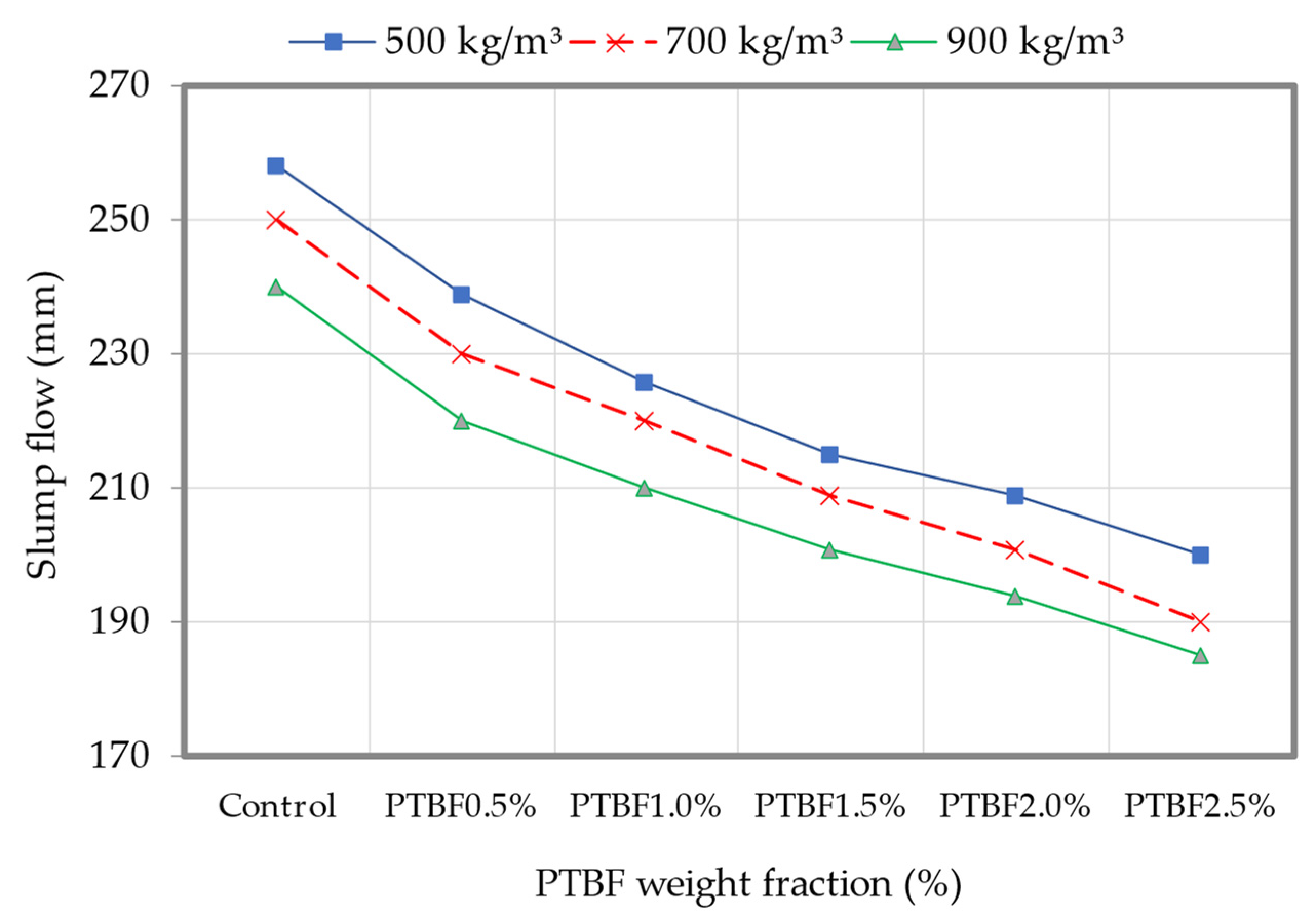
3.1. Slump Flow
3.2. Density
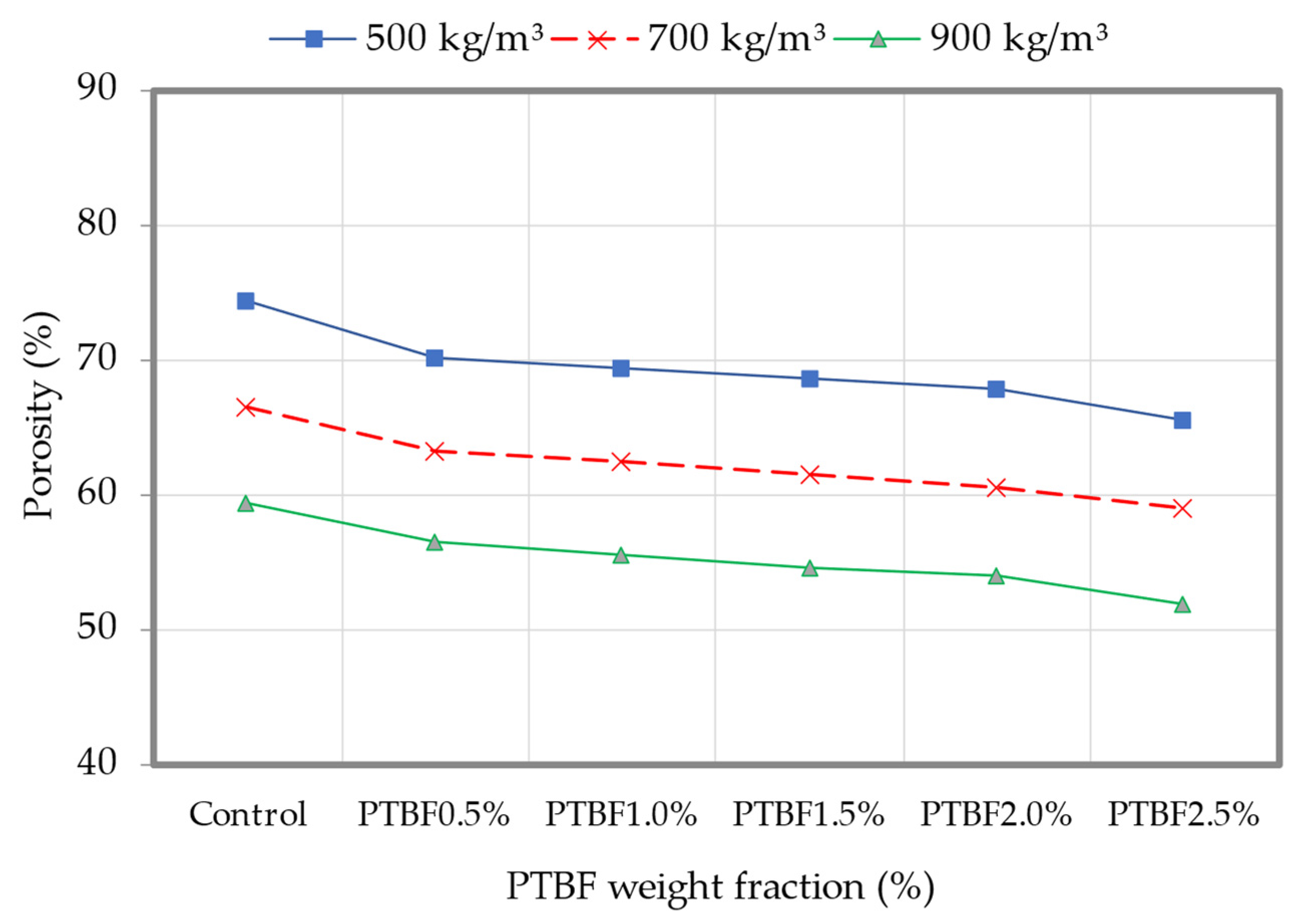
3.3. Porosity
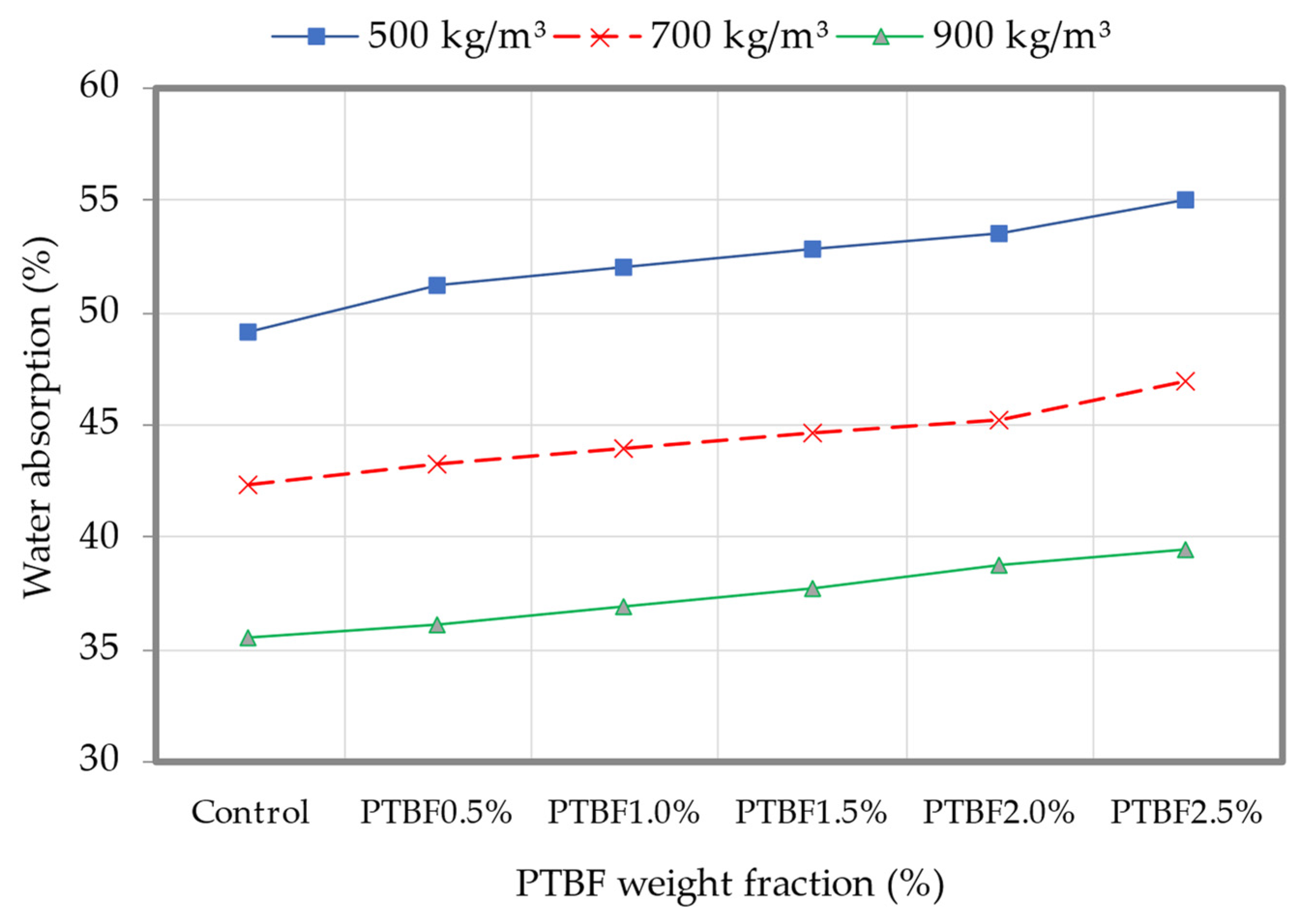
3.4. Water Absorption
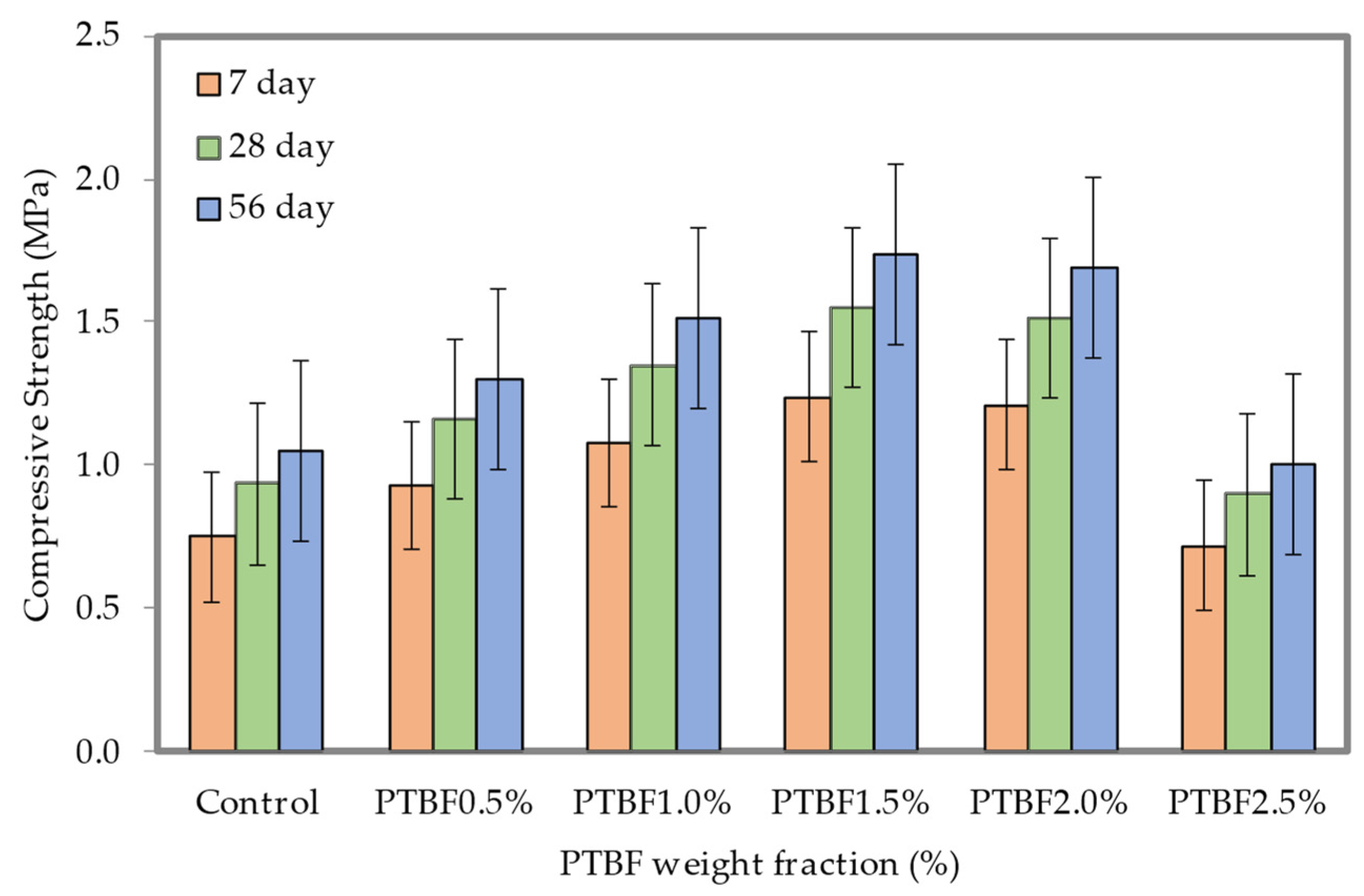
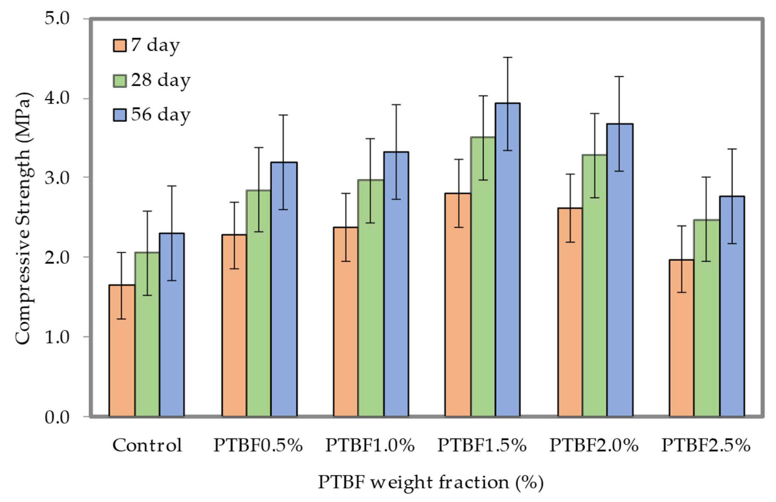
3.5. Compressive Strength
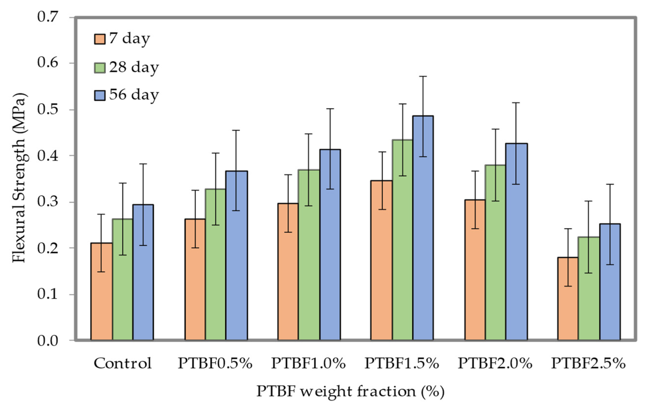
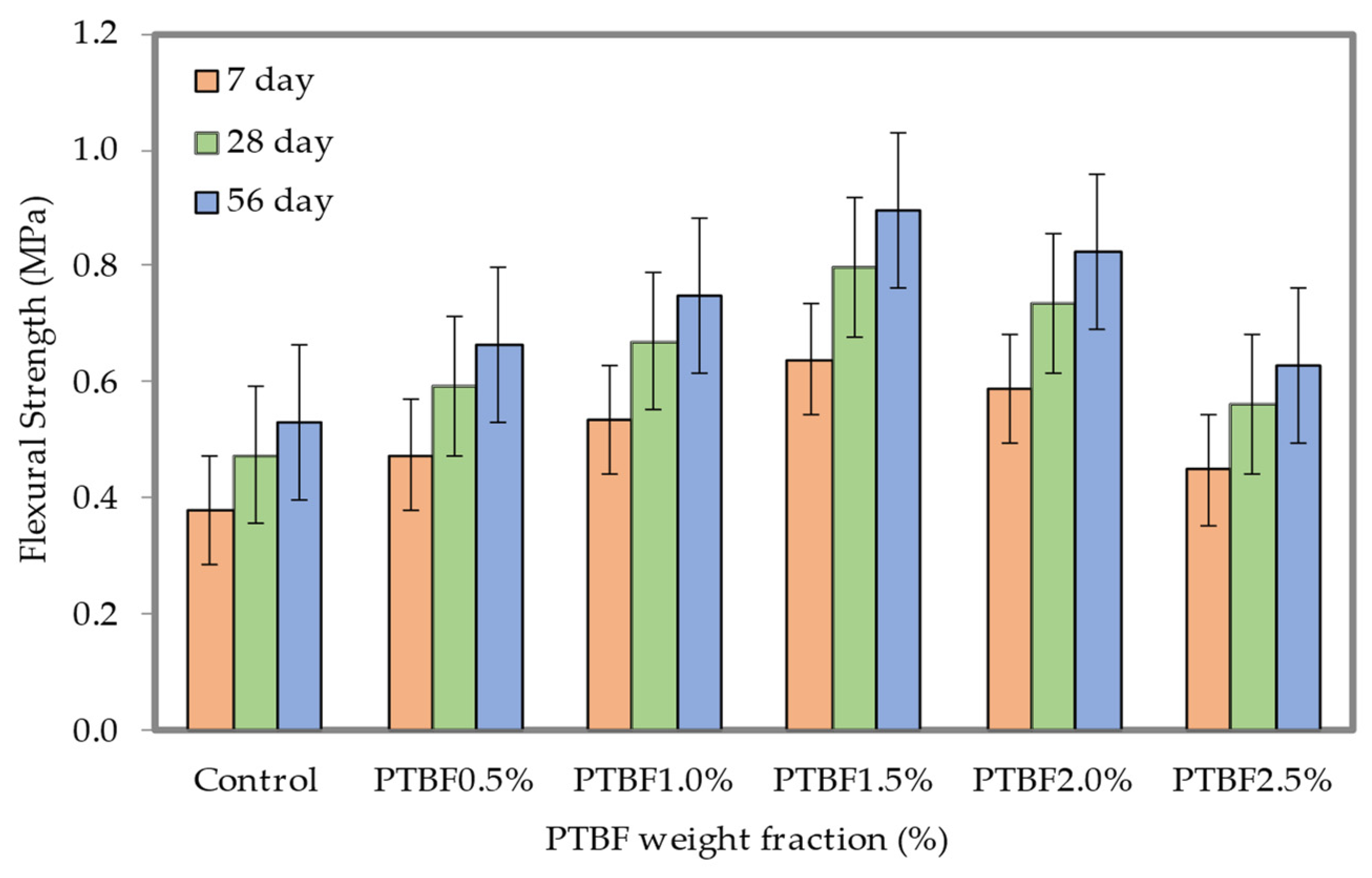
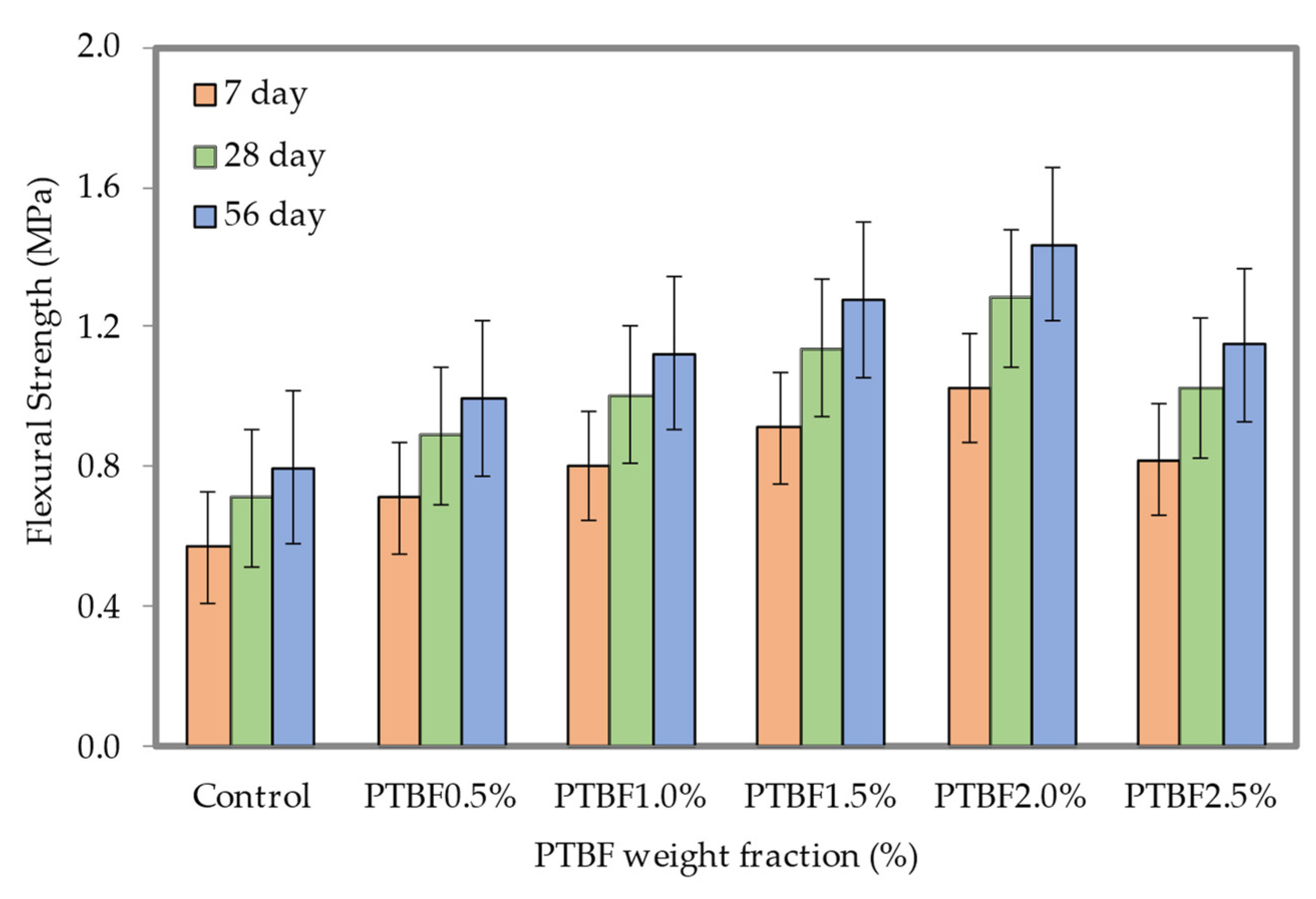
3.6. Flexural Strength
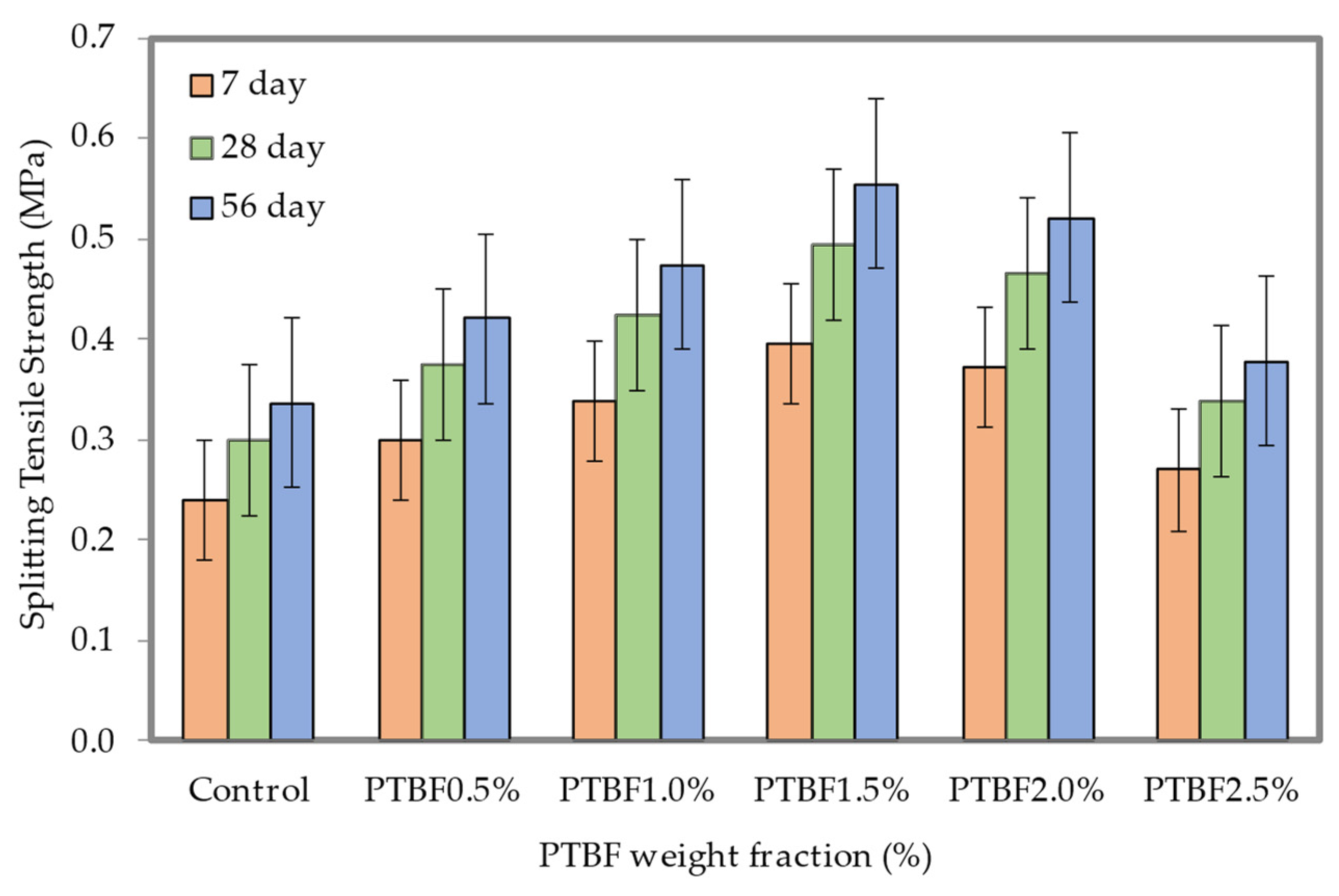
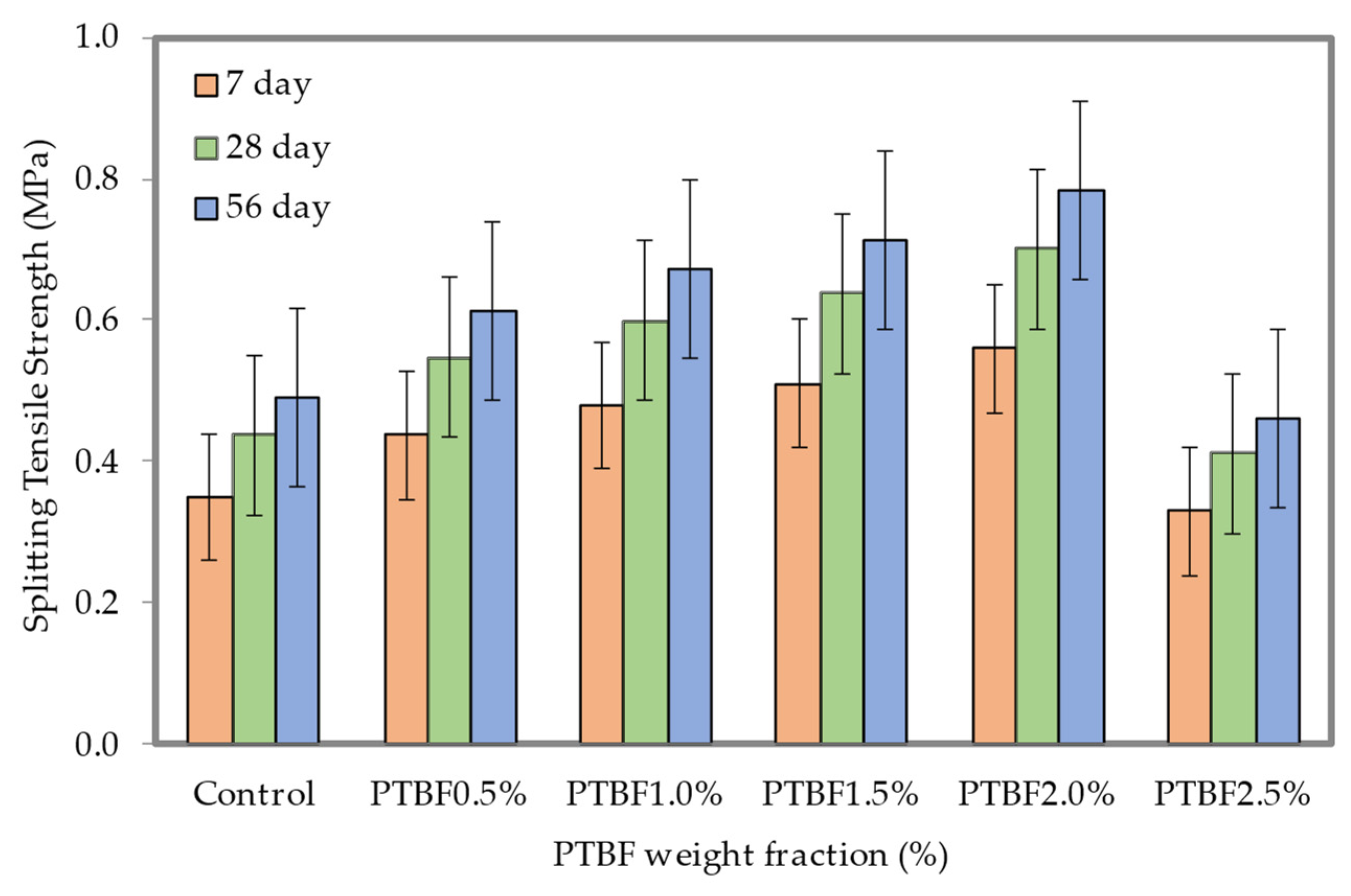
3.7. Splitting Tensile Strength
4. Discussion
4.1. Correlation between Water Absorption and Porosity
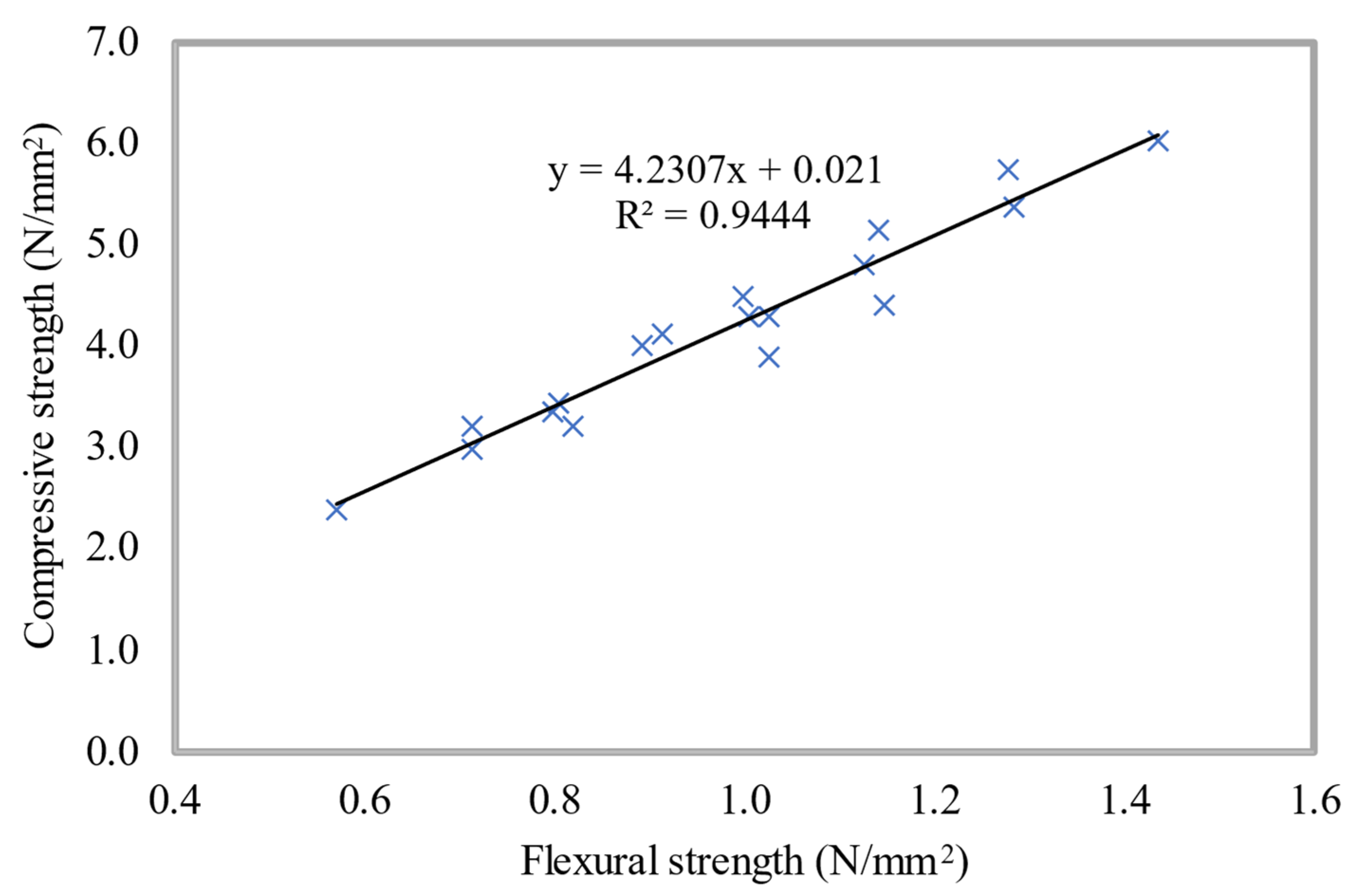
4.2. Correlation between the Compressive and Flexural Strengths
4.3. Correlation between the Compressive and Splitting Tensile Strengths
5. Conclusions
- Slump flow is reduced when PTBF is added to LFC because the fibers form a spatial network and the cement paste used to cover them is burned. Nonetheless, all LFC mixtures had a slump flow bigger than 185 mm, indicating strong self-flowing ability.
- The LFC dry density reduces as the PTBF weight fractions increase from 0.5% to 2.5% associated with the control specimen. The highest LFC dry density was obtained for the control specimen (0.0% PTBF) whereas the lowest density was obtained at 2.5% PTBF inclusion. The decrease in dry density at higher weight fractions of PTBF was due to the complexity of the compaction process which results in porous LFC.
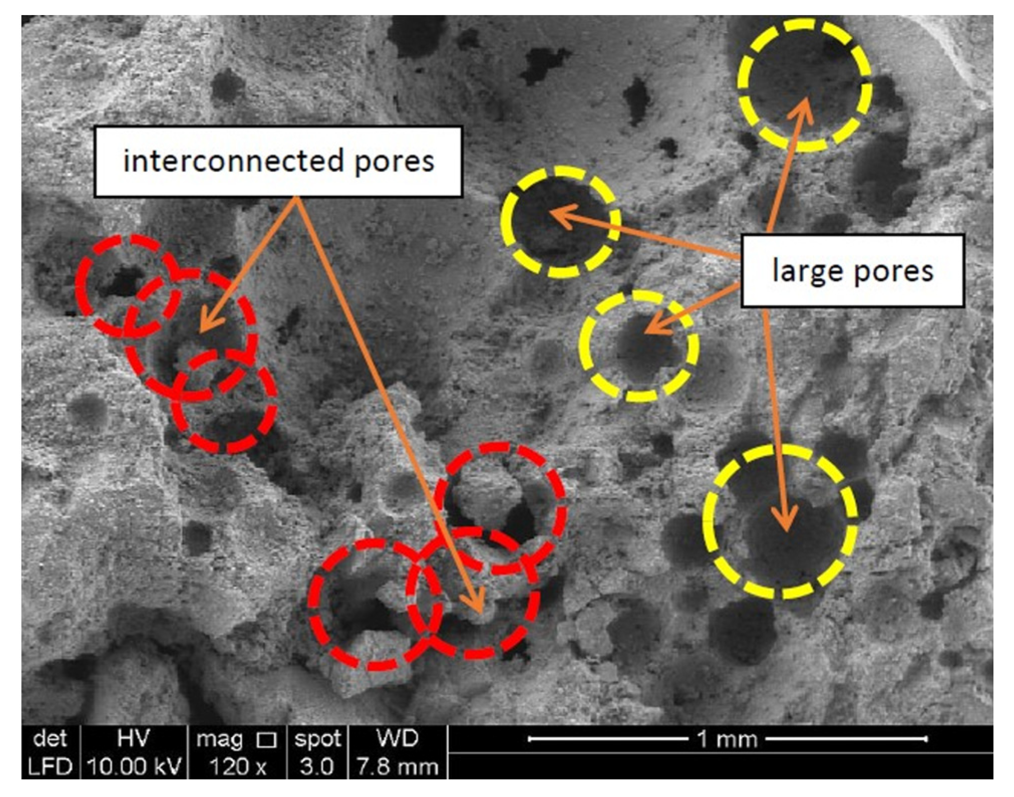
- The LFC porosity progresses progressively with the PTBF addition up to 2.5%. LFC mixed with 2.5% PTBF accomplished the ideal porosity with approximately a 12% decrease in comparison with the control LFC specimen for all three densities considered in this research. This is probably due to the excellent PTBF packing capability in the cement matrix of LFC.
- The water absorption of LFC increased with the rise in weight fractions of PTBF from 0.5% to 2.5%. The ideal water absorption capacity was accomplished with the addition of 2.5% of PTBF. LFC with the existence of PTBF in the mix has fewer cracks, and the cracks were less significant and finer than the LFC without the addition of PTBF. A linear relationship exists between the LFC water absorption capacity and its porosity for various PTBF weight fractions, indicating that as the LFC water absorption increases, the porosity increases as well.
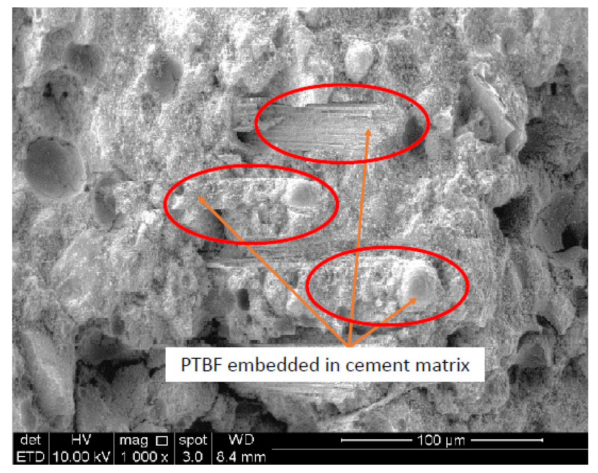
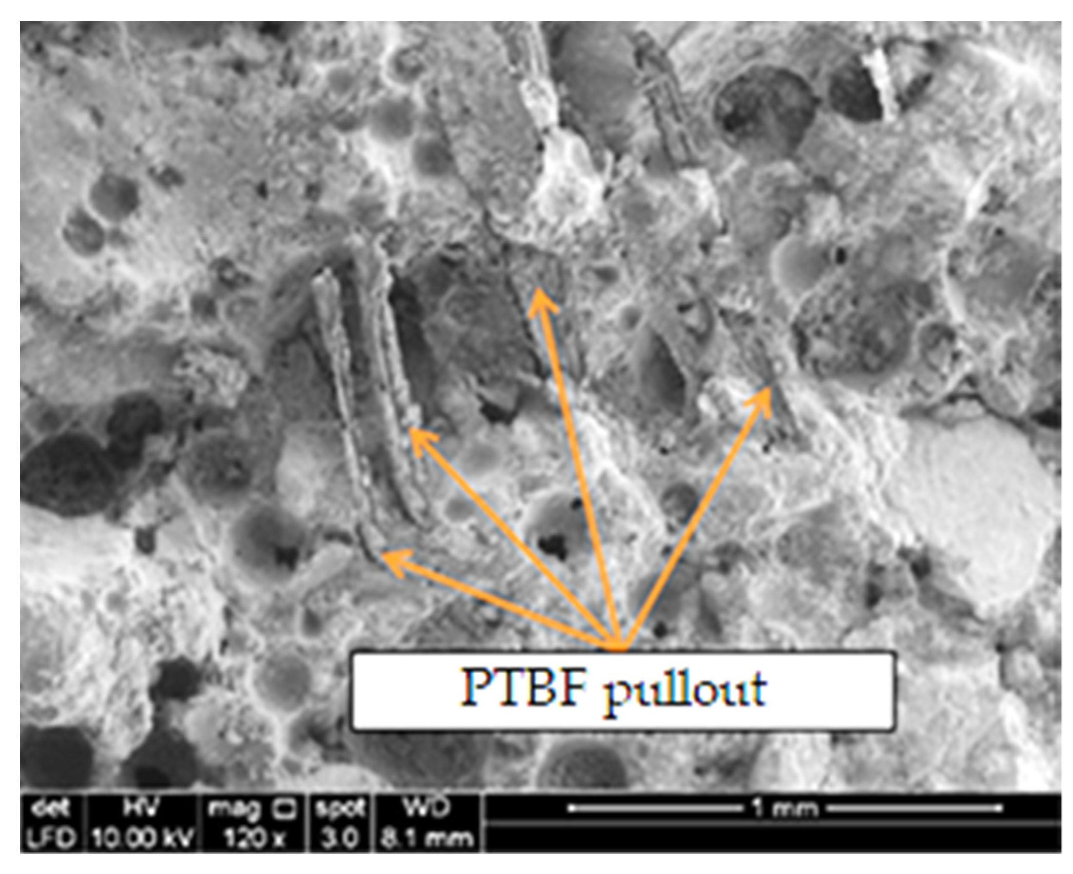
- The presence of PTBF in LFC augmented the flexural, compressive and splitting tensile strengths of LFC. For 500 and 700 kg/m3 densities, the optimal weight fraction of PTBF was 1.5%, while for the 900 kg/m3 density, the optimal weight fraction was 2.0%. With the inclusion of PTBF in LFC, there was a reduction in the entrapped air void, capillary pores, and entrained air voids, which boost the LFC’s strength properties. Beyond the 2.0% PTBF weight fraction, the LFC compressive, flexural and splitting tensile strengths diminished significantly. If the PTBF weight fractions were too high, the PTBF is difficult to disperse uniformly and causes agglomeration.
- Compressive strength and flexural strength of LFC can be distinguished by a direct expanding relationship, which denotes a highly linear relationship between the two strength parameters. The relationship demonstrates that the flexural strength of LFC increases with enhancing compressive strength. Additionally, the distribution of data supports the existence of a strong correlation between the splitting tensile and compressive strengths of LFC. In a similar pattern, the splitting tensile strengths rose with increasing compressive strength for all curing durations.
Author Contributions
Funding
Institutional Review Board Statement
Informed Consent Statement
Data Availability Statement
Conflicts of Interest
References
- Chica, L.; Alzate, A. Cellular concrete review: New trends for application in construction. Constr. Build. Mater. 2019, 200, 637–647. [Google Scholar] [CrossRef]
- Dhasindrakrishna, K.; Pasupathy, K.; Ramakrishnan, S.; Sanjayan, J. Progress, current thinking and challenges in geopolymer foam concrete technology. Cem. Concr. Compos. 2021, 116, 103886. [Google Scholar] [CrossRef]
- Mydin, M.A.O.; Phius, A.F.; Sani, N.; Tawil, N.M. Potential of Green Construction in Malaysia: Industrialised Building System (IBS) vs Traditional Construction Method. E3S Web Conf. 2014, 3, 01009. [Google Scholar] [CrossRef] [Green Version]
- Sadeghian, O.; Moradzadeh, A.; Mohammadi-Ivatloo, B.; Abapour, M.; Anvari-Moghaddam, A.; Lim, J.S.; Marquez, F.P.G. A comprehensive review on energy saving options and saving potential in low voltage electricity distribution networks: Building and public lighting. Sustain. Cities Soc. 2021, 72, 103064. [Google Scholar] [CrossRef]
- Sadineni, S.B.; Madala, S.; Boehm, R.F. Passive Building Energy Savings: A Review of Building Envelope Components. Renew. Sustain. Energy Rev. 2011, 15, 3617–3631. [Google Scholar] [CrossRef]
- Dey, V.; Bonakdar, A.; Mobasher, B. Low-velocity flexural impact response of fiber-reinforced aerated concrete. Cem. Concr. Compos. 2014, 49, 100–110. [Google Scholar] [CrossRef]
- Prakash, R.; Raman, S.N.; Subramanian, C.; Divyah, N. Eco-friendly fiber-reinforced concretes. In Handbook of Sustainable Concrete and Industrial Waste Management; Woodhead Publishing: Sawston, UK, 2022; pp. 109–145. [Google Scholar]
- Mohamad, N.; Iman, M.A.; Othuman Mydin, M.A.; Samad, A.A.A.; Rosli, J.A.; Noorwirdawati, A. Mechanical properties and flexure behaviour of lightweight foamed concrete incorporating coir fibre. IOP Conf. Ser. Earth Environ. Sci. 2018, 140, 012140. [Google Scholar] [CrossRef]
- Serri, E.; Suleiman, M.Z.; Mydin, M.A.O. The effects of oil palm shell aggregate shape on the thermal properties and density of concrete. Adv. Mat. Res. 2014, 935, 172–175. [Google Scholar] [CrossRef]
- Mohamad, N.; Samad, A.A.A.; Lakhiar, M.T.; Othuman Mydin, M.A.; Jusoh, S.; Sofia, A.; Efendi, S.A. Effects of Incorporating Banana Skin Powder (BSP) and Palm Oil Fuel Ash (POFA) on Mechanical Properties of Lightweight Foamed Concrete. Int. J. Int. Eng. 2018, 10, 69–76. [Google Scholar] [CrossRef]
- Ganesan, S.; Othuman Mydin, M.A.; Sani, N.M.; Che Ani, A.I. Performance of polymer modified mortar with different dosage of polymeric modifier. MATEC Web Conf. 2014, 15, 01039. [Google Scholar] [CrossRef] [Green Version]
- Song, P.S.; Hwang, S.; Sheu, B.C. Strength properties of nylon- and polypropylene-fiber-reinforced concretes. Cem. Concr. Res. 2005, 35, 1546–1550. [Google Scholar] [CrossRef]
- Ebrahimi, K.; Daiezadeh, M.J.; Zakertabrizi, M.; Zahmatkesh, F.; Korayem, A.H. A review of the impact of micro- and nanoparticles on freeze-thaw durability of hardened concrete: Mechanism perspective. Constr. Build. Mater. 2018, 186, 1105–1113. [Google Scholar] [CrossRef]
- Nambiar, E.K.K.; Ramamurthy, K. Air-void characterisation of foam concrete. Cem. Concr. Res. 2007, 37, 221–230. [Google Scholar] [CrossRef]
- Othuman Mydin, M.A.; Mohamed Shajahan, M.F.; Ganesan, S.; Sani, N.M. Laboratory investigation on compressive strength and micro-structural features of foamed concrete with addition of wood ash and silica fume as a cement replacement. MATEC Web Conf. 2014, 17, 01004. [Google Scholar] [CrossRef]
- Zhou, Y.; Bu, R.; Yi, L.; Sun, J. Heat Transfer Mechanism of Concurrent Flame Spread over Rigid Polyurethane Foam: Effect of Ambient Pressure and Inclined Angle. Int. J. Therm. Sci. 2020, 155, 106403. [Google Scholar] [CrossRef]
- Chung, S.-Y.; Lehmann, C.; Elrahman, M.A.; Stephan, D. Pore characteristics and their effects on the material properties of foamed concrete evaluated using Micro-CT images and numerical approaches. Appl. Sci. 2017, 7, 550. [Google Scholar] [CrossRef] [Green Version]
- Dhasindrakrishna, K.; Ramakrishnan, S.; Pasupathy, K.; Sanjayan, J. Collapse of fresh foam concrete: Mechanisms and influencing parameters. Cem. Concr. Compos. 2021, 122, 104151. [Google Scholar] [CrossRef]
- Falliano, D.; Parmigiani, S.; Suarez-Riera, D.; Ferro, G.A.; Restuccia, L. Stability, flexural behavior and compressive strength of ultra-lightweight fiber-reinforced foamed concrete with dry density lower than 100 kg/m3. J. Build. Eng. 2022, 51, 104329. [Google Scholar] [CrossRef]
- Jiang, J.; Lu, Z.; Niu, Y.; Li, J.; Zhang, Y. Study on the preparation and properties of high-porosity foamed concretes based on ordinary Portland cement. Mater. Des. 2016, 92, 949–959. [Google Scholar] [CrossRef]
- Oren, O.H.; Gholampour, A.; Gencel, O.; Ozbakkaloglu, T. Physical and Mechanical Properties of Foam Concretes Containing Granulated Blast Furnace Slag as Fine Aggregate. Constr. Build. Mater. 2020, 238, 117774. [Google Scholar] [CrossRef]
- Gencel, O.; Bilir, T.; Bademler, Z.; Ozbakkaloglu, T. A Detailed Review on Foam Concrete Composites: Ingredients, Properties, and Microstructure. Appl. Sci. 2022, 12, 5752. [Google Scholar] [CrossRef]
- Mansouri, I.; Shahheidari, F.S.; Hashemi, S.M.A.; Farzampour, A. Investigation of Steel Fiber Effects on Concrete Abrasion Resistance. Adv. Concr. Constr. 2020, 9, 367–374. [Google Scholar]
- Chajec, A.; Sadowski, L. The Effect of Steel and Polypropylene Fibers on the Properties of Horizontally Formed Concrete. Materials 2020, 13, 5827. [Google Scholar] [CrossRef] [PubMed]
- Hilal, A.A.; Thom, N.H.; Dawson, A.R. Pore Structure and Permeation Characteristics of Foamed Concrete. J. Adv. Concr. Technol. 2014, 12, 535–544. [Google Scholar] [CrossRef] [Green Version]
- Zhou, X.Y.; Yang, D.Y.; Zhu, C.X.; Wang, T.Z.; Zhao, X.T.; Liu, M. Durability of multi-scale polypropylene fiber reinforced concrete based on pore structure analysis. Mater. Sci. Eng. J. 2022, 40, 110–115. [Google Scholar]
- Farhad, A.; Ronny, G. Experimental investigation into the properties of self-compacting rubberised concrete incorporating polypropylene and steel fibers. Int. Fed. Struct. Concr. 2018, 20, 267–281. [Google Scholar]
- Karimipour, A. Effect of untreated coal waste as fine and coarse aggregates replacement on the properties of steel and polypropylene fibres reinforced concrete. Mech. Mater. 2020, 150, 103592. [Google Scholar] [CrossRef]
- Kamal, M.M.; Safan, M.A.; Etman, Z.A.; Kasem, B.M. Mechanical properties of self-compacted fiber concrete mixes. HBRC J. 2014, 10, 25–34. [Google Scholar] [CrossRef] [Green Version]
- Rai, B.; Singh, N.K. Statistical and experimental study to evaluate the variability and reliability of impact strength of steel-polypropylene hybrid fiber reinforced concrete. J. Build. Eng. 2021, 44, 102937. [Google Scholar] [CrossRef]
- Toutanji, H.A. Properties of polypropylene fiber reinforced silica fume expansive-cement concrete. Constr. Build. Mater. 1999, 13, 171–177. [Google Scholar] [CrossRef]
- Zhang, M.H.; Sharif, M.S.H.; Lu, G. Impact resistance of high-strength fiber reinforced concrete. Mag. Concr. Res. 2007, 9831, 199–210. [Google Scholar] [CrossRef]
- Kiran, T.; Ali Khan, S. Behaviour of Fibre Reinforced Concrete Slabs Under Impact Loads. Int. J. Curr. Res. 2017, 9, 60349–60354. [Google Scholar]
- Amancio, F.A.; De Carvalho Rafael, M.F.; De Oliveira Dias, A.R.; Bezerra Cabral, A.E. Behavior of concrete reinforced with polypropylene fiber exposed to high temperatures. Procedia Struct. Integr. 2018, 11, 91–98. [Google Scholar] [CrossRef]
- Hazlin, A.R.; Iman, A.; Mohamad, N.; Goh, W.I.; Sia, L.M.; Samad, A.A.A.; Ali, N. Microstructure and Tensile Strength of Foamed Concrete with Added Polypropylene Fibers. MATEC Web Conf. 2017, 103, 01013. [Google Scholar] [CrossRef] [Green Version]
- Ngo, S.H.; Huynh, T.P. lightweight foamed concrete reinforced with different polypropylene fiber contents. J. Sci. Technol. Civ. Eng. 2022, 16, 128–139. [Google Scholar] [CrossRef]
- Bing, C.; Zhen, W.; Ning, L. Experimental research on properties of high-strength foamed concrete. J. Mater. Civ. Eng. 2012, 24, 113–118. [Google Scholar] [CrossRef]
- Falliano, D.; De Domenico, D.; Ricciardi, G.; Gugliandolo, E. Compressive and flexural strength of fiber-reinforced foamed concrete: Effect of fiber content, curing conditions and dry density. Constr. Build. Mater. 2019, 198, 479–493. [Google Scholar] [CrossRef]
- Gencel, O.; Kazmi, S.M.S.; Munir, M.J.; Kaplan, G.; Bayraktar, O.Y.; Yarar, D.O.; Karimi Pour, A.; Ahma, M.R. Influence of bottom ash and polypropylene fibers on the physico-mechanical, durability and thermal performance of foam concrete: An experimental investigation. Constr. Build. Mater. 2021, 306, 124887. [Google Scholar] [CrossRef]
- BS 12; Specification for Portland Cement. British Standards Institute: London, UK, 1996.
- BS 882; Specification for Aggregates from Natural Sources for Concrete. British Standards Institute: London, UK, 1992.
- BS 1881-102; Testing Concrete. Method for Determination of Slump. British Standards Institute: London, UK, 1983.
- BS 12390-3; Testing Hardened Concrete. Compressive Strength of Test Specimens. British Standards Institute: London, UK, 2011.
- BS EN 12390-5; Testing Hardened Concrete. Flexural Strength of Test Specimens. British Standards Institute: London, UK, 2019.
- BS EN 12390-6; Testing Hardened Concrete. Tensile Splitting Strength of Test Specimens. British Standards Institute: London, UK, 2009.
- Brady, K.C.; Watts, G.R.A.; Jones, M.R. Specification for Foamed Concrete; Transport Research Laboratory: Great Britain, UK, 2001. [Google Scholar]
- BS 1881-122; Testing Concrete. Method for Determination of Water Absorption. British Standards Institute: London, UK, 1983.
- Hilal, A.A.; Thom, N.H.; Dawson, A.R. The use of additives to enhance properties of pre-formed foamed concrete. Int. J. Eng. Technol. 2015, 7, 286–293. [Google Scholar] [CrossRef] [Green Version]
- Hou, L.; Li, J.; Lu, Z.; Niu, Y. Influence of foaming agent on cement and foam concrete. Constr. Build. Mater. 2021, 280, 122399. [Google Scholar] [CrossRef]
- Wang, J.; Dai, Q.; Si, R.; Guo, S. Mechanical, durability, and microstructural properties of macro synthetic polypropylene (PP) fibre-reinforced rubber concrete. J. Clean. Prod. 2019, 234, 1351–1364. [Google Scholar] [CrossRef]
- Tambichik, M.A.; Abdul Samad, A.A.; Mohamad, N.; Mohd Ali, A.Z.; Othuman Mydin, M.A.; Mohd Bosro, M.Z.; Iman, M.A. Effect of combining Palm Oil Fuel Ash (POFA) and Rice Husk Ash (RHA) as partial cement replacement to the compressive strength of concrete. Int. J. Integr. Eng. 2018, 10, 61–67. [Google Scholar] [CrossRef]
- Ramezanianpour, A.A.; Esmaeili, M.; Ghahari, S.A.; Najaf, M.H. Laboratory study on the effect of polypropylene fiber on durability, and physical and mechanical characteristic of concrete for application in sleepers. Constr. Build. Mater. 2013, 44, 411–418. [Google Scholar] [CrossRef]
- Guo, Z.Q. Experimental Study on the Impermeability of Multi-Scale Polypropylene Fibre Concrete. Master’s Thesis, Chongqing University, Chongqing, China, 2018. [Google Scholar]
- Behfarnia, K.; Behravan, A. Application of high performance polypropylene fibers in concrete lining of water tunnels. Mater. Des. 2014, 55, 274–279. [Google Scholar] [CrossRef]
- Othman, R.; Jaya, R.P.; Muthusamy, K.; Sulaiman, M.; Duraisamy, Y.; Abdullah, M.M.A.B.; Przybył, A.; Sochacki, W.; Skrzypczak, T.; Vizureanu, P.; et al. Relation between Density and Compressive Strength of Foamed Concrete. Materials 2021, 14, 2967. [Google Scholar] [CrossRef] [PubMed]
- Zhang, Z.; Wang, H. The pore characteristics of geopolymer foam concrete and their impact on the compressive strength and modulus. Front. Mater. 2016, 3, 38. [Google Scholar] [CrossRef] [Green Version]
- Jitchaiyaphum, K.; Sinsiri, T.; Chindaprasirt, P. Cellular lightweight concrete containing pozzolan materials. Procedia Eng. 2011, 14, 1157–1164. [Google Scholar] [CrossRef] [Green Version]
- Aziz, I.H.; Abdullah, M.M.A.; Salleh, M.A.A.M.; Yoriya, S.; Abd Razak, R.; Mohamed, R.; Baltatu, M.S. The investigation of ground granulated blast furnace slag geopolymer at high temperature by using electron backscatter diffraction analysis. Arch. Metall. Mater. 2022, 67, 227–231. [Google Scholar]
- Paleu, C.C.; Munteanu, C.; Istrate, B.; Bhaumik, S.; Vizureanu, P.; Bălţatu, M.S.; Paleu, V. Microstructural Analysis and Tribological Behavior of AMDRY 1371 (Mo–NiCrFeBSiC) Atmospheric Plasma Spray Deposited Thin Coatings. Coatings 2020, 10, 1186. [Google Scholar] [CrossRef]
- Seker, B.; Gökçe, M.; Toklu, K. Investigation of the effect of silica fume and synthetic foam additive on cell structure in ultra-low density foam concrete. Case Stud. Constr. Mater. 2022, 16, e01062. [Google Scholar]
- Song, Y.; Lange, D. Influence of fine inclusions on the morphology and mechanical performance of lightweight foam concrete. Cem. Concr. Compos. 2021, 124, 104264. [Google Scholar] [CrossRef]
- Loghin, C.; Nicolaiov, P.; Ionescu, I.; Hoblea, Z. Functional Design of Equipment for Individual Protection. Manag. Technol. Chang. 2009, 2, 693–696. [Google Scholar]
- Ailenei, E.C.; Ionesi, S.D.; Dulgheriu, I.; Loghin, M.C.; Isopescu, D.N.; Maxineasa, S.G.; Baciu, I.-R. New Waste-Based Composite Material for Construction Applications. Materials 2021, 14, 6079. [Google Scholar] [CrossRef] [PubMed]
- Tolêdo Filho, R.D.; Joseph, K.; Ghavami, K.; England, G.L. The use of sisal fibre as reinforcement in cement-based composites. Rev. Bras. Eng. Agric. Ambient. 1999, 3, 245–256. [Google Scholar] [CrossRef] [Green Version]
- Khitab, A.; Serkan Kırgız, M.; Nehdi, M.L.; Mirza, J.; de Sousa Galdino, A.G.; Karimi Pour, A. Mechanical, thermal, durability and microstructural behavior of hybrid waste-modified green reactive powder concrete. Constr. Build. Mater. 2022, 344, 128184. [Google Scholar] [CrossRef]
- Amran, M.; Fediuk, R.; Vatin, N.; Huei Lee, Y.; Murali, G.; Ozbakkaloglu, T.; Klyuev, S.; Alabduljabber, H. Fibre-Reinforced Foamed Concretes: A Review. Materials 2020, 13, 4323. [Google Scholar] [CrossRef]
- Mydin, M.A.O.; Abdullah, M.M.A.B.; Mohd Nawi, M.N.; Yahya, Z.; Sofri, L.A.; Baltatu, M.S.; Sandu, A.V.; Vizureanu, P. Influence of Polyformaldehyde Monofilament Fiber on the Engineering Properties of Foamed Concrete. Materials 2022, 15, 8984. [Google Scholar] [CrossRef]
- Ariffin, N.; Abdullah, M.M.A.B.; Zainol, M.R.R.M.A.; Baltatu, M.S.; Jamaludin, L. Effect of Solid to Liquid Ratio on Heavy Metal Removal by Geopolymer-Based Adsorbent. IOP Conf. Ser. Mater. Sci. Eng. 2018, 374, 012045. [Google Scholar] [CrossRef] [Green Version]


| Properties | Value |
|---|---|
| Length | 37 mm |
| Equivalent diameter | 0.25 mm |
| Aspect ratio (L/D) | 148 |
| Density (g/cm3) | 0.975 |
| Young’s modulus | 5.25 GPa |
| Tensile strength | 575 MPa |
| Elongation at break | 3.18% |
| Thermal conductivity | 0.28 W/mK |
| Specific heat capacity | 1287 J/kgK |
| Melting temperature | 175 °C |
| Density (kg/m3) | PTBF (%) | Cement (kg/m3) | Sand (kg/m3) | Water (kg/m3) | Foam (kg/m3) | PTBF (kg/m3) |
|---|---|---|---|---|---|---|
| 500 | 0.0 | 194.1 | 291.2 | 87.4 | 46.3 | 0.0 |
| 500 | 0.5 | 194.1 | 291.2 | 87.4 | 46.3 | 3.1 |
| 500 | 1.0 | 194.1 | 291.2 | 87.4 | 46.3 | 6.2 |
| 500 | 1.5 | 194.1 | 291.2 | 87.4 | 46.3 | 9.3 |
| 500 | 2.0 | 194.1 | 291.2 | 87.4 | 46.3 | 12.4 |
| 500 | 2.5 | 194.1 | 291.2 | 87.4 | 46.3 | 15.5 |
| 700 | 0.0 | 266.3 | 399.5 | 119.9 | 40.0 | 0.0 |
| 700 | 0.5 | 266.3 | 399.5 | 119.9 | 40.0 | 4.1 |
| 700 | 1.0 | 266.3 | 399.5 | 119.9 | 40.0 | 8.3 |
| 700 | 1.5 | 266.3 | 399.5 | 119.9 | 40.0 | 12.4 |
| 700 | 2.0 | 266.3 | 399.5 | 119.9 | 40.0 | 16.5 |
| 700 | 2.5 | 266.3 | 399.5 | 119.9 | 40.0 | 20.6 |
| 900 | 0.0 | 338.6 | 507.9 | 152.4 | 33.8 | 0.0 |
| 900 | 0.5 | 338.6 | 507.9 | 152.4 | 33.8 | 5.2 |
| 900 | 1.0 | 338.6 | 507.9 | 152.4 | 33.8 | 10.3 |
| 900 | 1.5 | 338.6 | 507.9 | 152.4 | 33.8 | 15.5 |
| 900 | 2.0 | 338.6 | 507.9 | 152.4 | 33.8 | 20.7 |
| 900 | 2.5 | 338.6 | 507.9 | 152.4 | 33.8 | 25.8 |
Disclaimer/Publisher’s Note: The statements, opinions and data contained in all publications are solely those of the individual author(s) and contributor(s) and not of MDPI and/or the editor(s). MDPI and/or the editor(s) disclaim responsibility for any injury to people or property resulting from any ideas, methods, instructions or products referred to in the content. |
© 2023 by the authors. Licensee MDPI, Basel, Switzerland. This article is an open access article distributed under the terms and conditions of the Creative Commons Attribution (CC BY) license (https://creativecommons.org/licenses/by/4.0/).
Share and Cite
Mydin, M.A.O.; Abdullah, M.M.A.B.; Razak, R.A.; Nawi, M.N.M.; Risdanareni, P.; Puspitasari, P.; Sandu, A.V.; Baltatu, M.S.; Vizureanu, P. Study on Polypropylene Twisted Bundle Fiber Reinforced Lightweight Foamed Concrete. Buildings 2023, 13, 541. https://doi.org/10.3390/buildings13020541
Mydin MAO, Abdullah MMAB, Razak RA, Nawi MNM, Risdanareni P, Puspitasari P, Sandu AV, Baltatu MS, Vizureanu P. Study on Polypropylene Twisted Bundle Fiber Reinforced Lightweight Foamed Concrete. Buildings. 2023; 13(2):541. https://doi.org/10.3390/buildings13020541
Chicago/Turabian StyleMydin, Md Azree Othuman, Mohd Mustafa Al Bakri Abdullah, Rafiza Abdul Razak, Mohd Nasrun Mohd Nawi, Puput Risdanareni, Poppy Puspitasari, Andrei Victor Sandu, Madalina Simona Baltatu, and Petrica Vizureanu. 2023. "Study on Polypropylene Twisted Bundle Fiber Reinforced Lightweight Foamed Concrete" Buildings 13, no. 2: 541. https://doi.org/10.3390/buildings13020541
APA StyleMydin, M. A. O., Abdullah, M. M. A. B., Razak, R. A., Nawi, M. N. M., Risdanareni, P., Puspitasari, P., Sandu, A. V., Baltatu, M. S., & Vizureanu, P. (2023). Study on Polypropylene Twisted Bundle Fiber Reinforced Lightweight Foamed Concrete. Buildings, 13(2), 541. https://doi.org/10.3390/buildings13020541