Article

Evaluation of the Residual Seismic Capacity of Post-Earthquake Damaged RC Columns Based on the Damage Distribution Model

1
State Key Laboratory of Green Building in Western China, Xi’an University of Architecture & Technology, Xi’an 710055, China
2
School of Civil Engineering, Xi’an University of Architecture and Technology, Xi’an 710055, China
*
Authors to whom correspondence should be addressed.
Buildings 2023, 13(3), 595; https://doi.org/10.3390/buildings13030595
Submission received: 1 February 2023 / Revised: 15 February 2023 / Accepted: 21 February 2023 / Published: 23 February 2023

Abstract

:
Evaluation of the residual seismic capacity (RSC) of post-earthquake damaged buildings is instrumental to the formation of reasonable recovery strategies. At present, incremental dynamic analysis (IDA) that considers the mainshock and aftershock is the method most frequently used to evaluate the RSC of damaged structures. However, the mainshock-induced structural damage determined using the IDA method may be inconsistent with the damage observed in actual engineering. This inconsistency could potentially lead to an unreasonable evaluation result. To overcome this drawback, it is necessary to evaluate the RSC of damaged structures according to their observed damage instead of that obtained by the IDA. In this paper, a method of evaluating the RSC of damaged reinforced concrete (RC) columns is proposed. First, the damage degree and distribution of the damaged columns were evaluated via visual inspection after mainshocks. Then, a numerical model was developed to predict the residual behavior of damaged columns subjected to aftershocks. After that, the RSC of damaged columns was estimated based on fragility analysis. The degradation of the collapse capacity of damaged columns was quantified by the collapse fragility index (CFI), and a parameter analysis was conducted to study the effect of structural parameters on the CFI of damaged columns. Lastly, an empirical model for predicting the CFI was proposed, facilitating the application of this study in actual post-earthquake assessments. The parameter analysis indicates that the axial load ratio of the columns and the degree of damage degree accumulated during mainshocks have a significant effect on the CFI. Additionally, the proposed empirical model can effectively predict the degradation of the collapse capacity of RC columns in existing test data, with an accuracy of 0.82.

1. Introduction

It has been observed in recent earthquakes that well-designed buildings demonstrate excellent seismic performance, and that the earthquake-induced casualties and economic losses of well-designed buildings are significantly reduced. However, these buildings are vulnerable to damage in strong earthquakes due to their ductile design requirements. Earthquake-induced (mainshock-induced) damage to buildings may lead to the degradation of RSC, with potentially catastrophic consequences. A famous example was the Canterbury television (CTV) building, which was damaged during the Mw7.1 mainshock in September 2010 and was allocated a green placard (no restriction on use or occupancy). However, it collapsed during the aftershock on 22 February 2011 and one hundred and fifteen people lost their lives as a result. Evaluation of the residual seismic capacities (RSC) of damaged buildings is an essential part of post-earthquake decision making. However, studies focused on mainshock-damaged buildings are very scarce, creating difficulties in the quantification of their RSC in aftershocks. In light of this, engineers tend to make conservative assessments to avoid tragedies such as that of the CTV building. For example, a damaged building may require demolition even if it can resist potential aftershocks. Therefore, determining the RSC of damaged structures is critical to the further development of post-earthquake assessment theory.
Currently, post-earthquake assessment of damaged buildings is based on the visual damage observed during field inspections [1]. The mainshock-induced damage to structural components is usually categorized as slight, moderate, severe, or extreme according to the visual damage phenomena [2]. For example, a column can be considered moderately damaged if crushing of the cover concrete is observed. There have been many achievements related to the relationship between the damage state and visual damage phenomena [3,4,5,6,7], enriching the qualitative description found in the post-earthquake assessment guidelines worldwide. A preliminary assessment of the inadequacy of existing RC buildings in terms of their seismic capacity is another fundamental phase in ensuring a proper choice of effective retrofitting strategies [8,9,10]. Accordingly, quantitative evaluation of the RSC of damaged buildings in aftershocks has become a critical subject in post-earthquake assessment theory, whereas studies related to buildings damaged at the structural and component level are scarce. For the damaged components and structures, the related studies have focused on damage identification [11], degradation of structural key performance parameters [12], and the shift of the basic frequency [13]. It should be pointed out that the prediction of the residual hysteretic behaviors of damaged components and structures is rare. In other words, there is a lack of numerical models for damaged components and structures when evaluating their RSC. As a result, scholars and engineers must seek alternative methods of post-earthquake assessment.
Time history analysis considering mainshock–aftershock sequences is commonly used for evaluating the RSC of damaged components and structures. Focusing on the aftershock safety assessment of post-earthquake buildings, Burton and Deierlein [14] proposed a collapse capability assessment method for post-earthquake buildings based on time history analysis. Shokrabadi and Burton [15] evaluated the residual capacity of post-earthquake RC frames in aftershocks. Abdelnaby [16], Raghunandan, Liel and Luco [17] evaluated the failure probability of post-earthquake damaged RC frames in aftershocks. Trapani and Malavisi [18] evaluated the residual capacity and fragility of post-earthquake damaged RC frames in aftershocks. Iervolino, Chioccarelli, and Suzuki [19] evaluated the seismic damage accumulation of RC structures in multiple mainshock–aftershock sequences. Furtadoa, Rodrigues, Varuma et al. [20] analyzed the characteristics of damage accumulation in aftershocks for masonry structures. Focusing on the aftershock safety assessment of regional buildings in aftershocks, Lu, Cheng, Xu et al. [21] investigated the effect of ground motion characteristics based on nonlinear dynamic analysis considering mainshock–aftershock sequences. In these studies, the mainshock damage was determined according to the numerical results of time history analysis rather than the damage phenomena observed in the post-earthquake field; this is in contrast with the results of time history analyses, which are instead influenced by various factors [22]. As a result, the mainshock-caused damage obtained via time history analysis may be inconsistent with post-earthquake observations, which in turn may result in an inaccurate evaluation of the RSC of damaged components and structures. Therefore, it is necessary to develop alternative methods with which to evaluate the RSC of damaged components and structures.
This study aims to develop a new method of evaluating the RSC of mainshock-damaged RC columns. Compared with the aforementioned studies, the novelty of the proposed method is that the residual seismic capacity of columns can be evaluated based on their actual post-earthquake damage phenomena. The organization of the study is as follows. In Section 1, the evaluation method of the RSC of the damaged RC columns is introduced. In contrast with existing studies, the effect of mainshock damage to RC columns is analyzed according to observed damage phenomena instead of dynamic analysis. Section 2 presents a case study in which the proposed method was applied to 41 full-scale RC columns selected from the PEER database. In Section 3, we describe a parameter analysis conducted to discuss the effect of different factors on the degradation of the seismic capacity of damaged columns. Lastly, an empirical model is developed to rapidly estimate the seismic capacity degradation of damaged columns, facilitating the potential use of the proposed method in post-earthquake engineering.

2. Analysis Method of the RSC of Post-Earthquake Damaged RC Columns

2.1. Overview of Methodology

The method proposed in this paper includes three different paths, as shown in Figure 1. The response of buildings in a real earthquake can hardly be obtained, and the guidelines of post-earthquake assessment in different countries are usually based on the visible damage phenomenon of buildings after an earthquake. Therefore, the methodology starts with the visual inspection of columns in a post-earthquake field. The purpose of this is to ascertain the visible damage phenomenon of the damaged columns and to evaluate the degree of damage inflicted (i.e., damage index DI). Then, the damage distribution of materials in damaged columns can be quantified. The maximum strain of material experienced in the mainshock is defined as damaged strain, which is a key indicator used to estimate the residual behavior of damaged materials. Path 1 concludes with the output of the damaged strain of materials in damaged columns, which facilitates the prediction of the residual mechanical performance of the damaged columns.
Path 2 begins by establishing the numerical model for the damaged columns. To confirm the reasonability of the numerical model, the residual load–displacement of damaged columns with the numerical model should be compared with test data. Later, the performance of damaged columns subjected to subsequent earthquakes can be analyzed based on the incremental dynamic analysis (IDA) method. Through the IDA method, the maximum strength of subsequent earthquakes that a damaged column can withstand can be predicted. The aim of path 2 is to provide data with which to estimate the collapse probability of the columns under subsequent earthquakes.
In path 3, we first analyzed the collapse fragility of the columns in different mainshock-caused damage states. Based on the results, the collapse likelihood of those damaged columns was discussed. Generally, the seismic capacity of a structure is defined as the intensity of ground motion corresponding to the collapse of a structure. In second-generation performance-based earthquake engineering (PBEE), direct economic losses, indirect economic losses, and casualties caused by earthquakes are used as performance parameters which quantify and describe the seismic capability of probabilistic structures. This probability is typically chosen by decision makers and may be connected to factors such as the local population, economic level, etc. This is not the topic of this paper. Thus, as seen in several relevant studies [23,24], the authors chose a ground motion intensity corresponding to a 50% probability of collapse as the seismic capacity of the structure. The CFI was proposed to quantify the degradation of the RSC of damaged columns. Path 3 ends with a parameter study, which reveals the influence of structural parameters on CFI. To facilitate the practical use of the study, an empirical model was established to predict CFI.

2.2. Quantification of Damage to Columns

Post-earthquake inspections are important ways to assess the safety of damaged buildings. The purpose of a post-earthquake inspection is to determine the visible damage phenomena of damaged buildings, which are then used to evaluate the degree of damage and distribution caused by the earthquakes. Here, an estimation of the degree and distribution of damaged RC columns according to the inspected phenomena is presented.

2.2.1. Estimation of Damage Degree

The damage degree (also called the damage state or damage level) of RC components after earthquakes is usually classified as slight, moderate, severe, or extreme. Those damage degrees of RC columns are qualitatively described by visible damage phenomena, such as concrete spalling, exposure of reinforcements, etc. For example, moderately damaged RC columns are characterized by spalling of the cover concrete [3,4,5,6,7,8]. Each damage degree corresponds to a specific range of damage index (DI). The relationship between damage degree, DI, and visible damage phenomena [25] has been thoroughly investigated. Once the visible damage phenomena of a damaged column are inspected, its damage degree and the corresponding DI can be estimated.

2.2.2. Damage Distribution of Materials

In the proposed method, the numerical model of damaged columns is needed for the evaluation of their RSC. Quantification of the distribution of damaged materials in damaged components helps to reasonably model the residual response of damaged columns in subsequent earthquakes. Here, the damage distribution of materials in damaged columns was quantified with reference to the author’s previous work, i.e., the damage distribution model [26]. The distribution of concrete damage in columns is
ξ X , Y = 8.12 e Y / 0.3 + 0.65 D I X h h 0 ε c c ε n o r , 0.07 Y 1 7.063 D I X h h 0 ε c c ε n o r , 0 Y < 0.07
where (X, Y) is the normalized coordinate of the material; X = 2x/h, Y = y/1.5 h, x, y is the distance of concrete to the section centroid and the column bottom; h0 is the depth of the section along the loading direction minus the depth from the inner edge of the stirrup to the surface of the member. Figure 2 is the schematic diagram of the material location. ξ(X, Y) is the damage strain ratio of the concrete at coordinate (X, Y), expressed as:
ξ X , Y = ε d X , Y ε n o r
where εd is the damaged strain of concrete, defined as the maximum compressive strain of concrete in the earthquake, and εnor is the normalized strain. The peak strain εc and εcc, respectively corresponding to the cover and the confined concrete, are used as the normalization strains. The reinforcement damage to columns is:
ξ s X , Y = X h h 0 R s Y D I
where ξs(X, Y) is the damage strain ratio of reinforcements at coordinate (X, Y). Rs(Y) is the relationship coefficient and the values at Y = 0.121, Y = 0.384, Y = 0.672, and Y = 1 are 11.312, 10.141, 2.413, and 1.731, respectively. When Y is between the two fitting points, Rs(Y) is determined by linear interpolation. The damage strain ratio of reinforcements ξs(X, Y) is the ratio of its damaged strain εd,s(X, Y) over the strain corresponding to its yield strength εy.
Equations (1) and (3) quantified the relationship between the material’s damage distribution and column damage degree. With those equations, the damaged strain of cover concrete, confined concrete, and reinforcements in damaged columns can be quantified after imputing estimated DI and other parameters.

2.3. Numerical Model

The fiber beam–column element is a widely used numerical model in the performance evaluation of structures. The cross-section is divided into different fibers with the corresponding stress–strain relationship. Through the equilibrium analysis, the sectional moment–curvature response can be obtained with the plane section assumption. Additionally, then, the force and displacement of the structures can be determined based on the finite element analysis method. In other words, the residual behavior of damaged columns can be modeled once the residual stress–strain relation of the materials is determined. The remainder of Section 2.3 presents the estimation of the residual stress–strain relation of the different materials according to their damaged strain.
The cover concrete and confined concrete can be considered intact if their damaged strain is less than εc than εcc. Otherwise, their strength is degraded and the residual strength can be estimated according to Equations (4) and (5).
f c , d X , Y = f c 1 Z ε c , d X , Y ε c
where fc,d(X, Y) is the residual compressive strength corresponding to εc,d(X, Y); εc,d(X, Y) is the damaged strain of cover concrete at coordinates (X, Y); fc denotes the compressive strength of the cover concrete before the action earthquake and εc is the corresponding strain. Z is a parameter in the Kent–Park model [27].
f c c , d X , Y = f c c ε c c , d X , Y / ε c c η η 1 + ε c c , d X , Y / ε c c η
where fcc,d(X, Y) is the residual strength corresponding to εcc,d (X, Y); εcc,d (X, Y) is the damaged strain of confined concrete at coordinates (X, Y); fcc denotes the compressive strength of the confined concrete of the undamaged column and εcc is the corresponding strain. η = Ec/(EcEsec) is the parameter in Mander’s model [28], while Ec denotes the elastic modulus of confined concrete prior to the action of the earthquake. Similarly, Esec is the secant modulus.
The stress–strain relationship of reinforcements is usually simplified by a bilinear model. If the damaged strain is greater than εy, the reinforcements enter into the hardening stage and their residual strength is expressed as follows:
f y , d X , Y = f y + b s E s ε s , d X , Y ε y
where fy,d(X, Y) is the residual strength corresponding to εy,d(X, Y); εy,d(X, Y) is the damaged strain of reinforcements at coordinates (X, Y); fy and εy denote the yield strength and yield strain of intact reinforcements, respectively; bs is the strain hardening ratio of the undamaged reinforcement; and Es is their elastic modulus.
After the quantification of the damaged strain, the residual strength of different materials can be estimated according to Equations (4)–(6), and the numerical model of damaged RC columns can then be developed. The nodes, elements, and sectional discretization of the model are consistent with those presented in a previous work [26].

2.4. Evaluation of Residual Seismic Capacity

Probability-based earthquake engineering has become the main developmental trend in the field of seismic engineering in recent years [29,30]. The probability of structures reaching or exceeding their capacity can be obtained via fragility analyses. In this section, a probability-based evaluation of RSC (i.e., collapse capacity in sequent earthquakes) of damaged RC columns is proposed.

2.4.1. Incremental Dynamic Analysis

Generally, the dynamic equation of a single-degree-of-freedom (SDOF) column under earthquakes can be expressed as
M u ¨ t + C u ˙ t + K u t = M u ¨ g t
where M is the mass of the system; C denotes the damping matrix and K denotes the stiffness matrix;  u ¨ t is the acceleration responses of the SDOF under the acceleration time history;  u ˙ t and  u t are, respectively, velocity and displacement responses; and  u ¨ g t is the acceleration time history of a ground motion. A time history response, such as displacement of the column under a given level of earthquake intensity, can be solved by imputing the ground motion records into Equation (7). Additionally, the maximum displacement of columns at this earthquake intensity can be obtained.
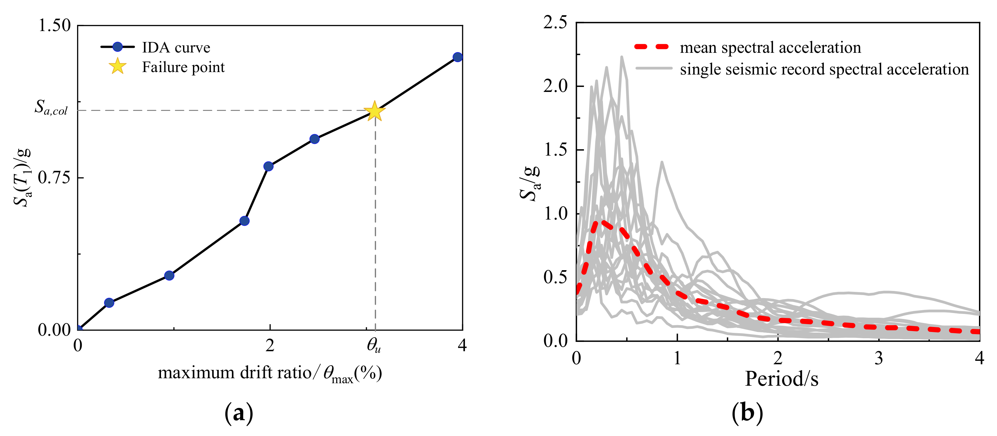
The IDA method scales the intensity of one (or more) ground motion records to obtain a curve (or more) that parameterizes the response with the intensity level, as shown in Figure 3. Sa(T1), commonly used in engineering seismic studies, is used as the ground motion intensity measure in this paper, where Sa(T1) refers to the 5% damped elastic spectrum acceleration corresponding to the fundamental vibration period of the structure. The maximum drift ratio of columns θmax under each level of earthquake intensity is used to evaluate the RSC. The column is considered to be collapsed under the earthquake intensity when θmax is equal to the ultimate drift ratio θu, and the corresponding earthquake intensity represents the maximum intensity the column can resist, denoted as Sa,col in Figure 3a. To reduce the influence of the uncertainty of ground motions, 21 representatives’ far-field seismic records, recommended in the ATC-63 report [23], are used for IDA. The spectral acceleration curves of the selected seismic records are shown in Figure 3b.

2.4.2. Ultimate Drift Ratio of Damaged Columns

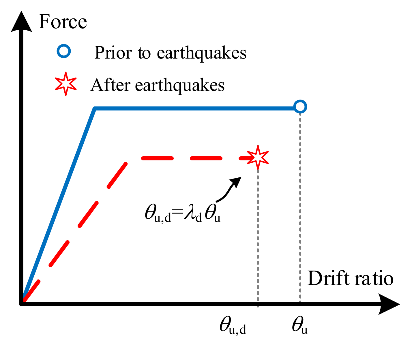
The mainshock-related damage to columns will decrease their drift capacity in aftershocks [31], meaning that the ultimate drift ratio of damaged columns θu,d may be smaller than that prior to earthquakes θu, as shown in Figure 4. To consider this effect, a reduction factor λd is here introduced, and θu,d = λdθu. According to FEMA 306 [12], λd is adopted, respectively, as 1.0, 0.9, 0.8, and 0.7 for slightly, moderately, severely, and extremely damaged columns in this paper.

2.4.3. Collapse Fragility of Damaged Column

The probabilistic collapse capacity of damaged columns is expressed by the fragility function. The expression is shown as follows:
P [ θ max θ u , d | S a T 1 ] = Φ ln θ max ln θ u , d β c 2 + β d 2
where P[θmaxθu,dSa(T1)] is the collapse probability of the damaged columns under the earthquake intensity Sa(T1); Φ[•] is the standardized normal cumulative distribution function. βc and βd represent logarithmic standard deviations for the seismic demand and capacity. When the Sa(T1) is taken as the intensity measure of the fragility analysis,  β c 2 + β d 2 can be estimated as 0.4 [32]; ln(θmax) can be calculated according to the result of IDA.
ln θ max = A + B ln S a T 1
where A and B are determined by a linear regression of ln(θmax) and ln(Sa(T1)).
The fragility results are obtained according to Equation (8). Next, the residual collapse capacity of columns can be determined using the Sa(T1) corresponding to the 50% collapse probability of the fragility curve. The validity of the numerical model of damage columns is the basis of the accurate evaluation of residual collapse capacity. In this paper, the damage distribution of the numerical model is quantified according to the DI, which is estimated in light of the actual post-earthquake damage phenomenon. This means the proposed method can evaluate the RSC of columns based on the actual post-earthquake damage phenomenon.

3. Example Application and Discussions

The proposed evaluation method of RSC for aged and damaged structures was applied to RC columns selected from the PEER database. In Section 3.1, the principles of selecting columns from PEER database are introduced. To demonstrate the reasonability of the numerical model in the proposed method, the model results of residual load–displacement curves of RC columns in different damage states are compared with the test results in Section 3.2. In Section 3.3 the residual collapse capacity of earthquake-damaged RC columns is quantified based on fragility analysis and the CFI is calculated. Finally, the CFI is used to analyze structural parameters, which provides a reference for the rapid evaluation of the residual collapse capacity of structures after major earthquakes.

3.1. Test Database of RC Columns

The size effect has an undeniable influence on the load–displacement response of RC columns. When selecting test data, full-scale columns are preferred because their behavior is close to that which occurs in actual engineering. Moreover, this paper targets flexural dominated columns, so short columns where shear effect cannot be neglected are not considered. Based on the above principles, a total of 41 column specimens were selected from the PEER database [33,34,35,36,37,38,39,40,41,42,43,44]. The detailed parameters of selected columns are shown in Table A1 in the Appendix A. Later, the residual load–displacement response of those columns will be analyzed using the proposed numerical model.

3.2. Validation of the Numerical Model

According to Section 2.2, the damage distribution of the selected RC columns in slight, moderate, severe, and extreme damage states was quantified. To help the readers repeat the authors’ work, the damaged strain and ultimate strain of the extreme fibers of confined concrete are shown in Table 1; the εcc,d of the intact state is equivalent to εcc.
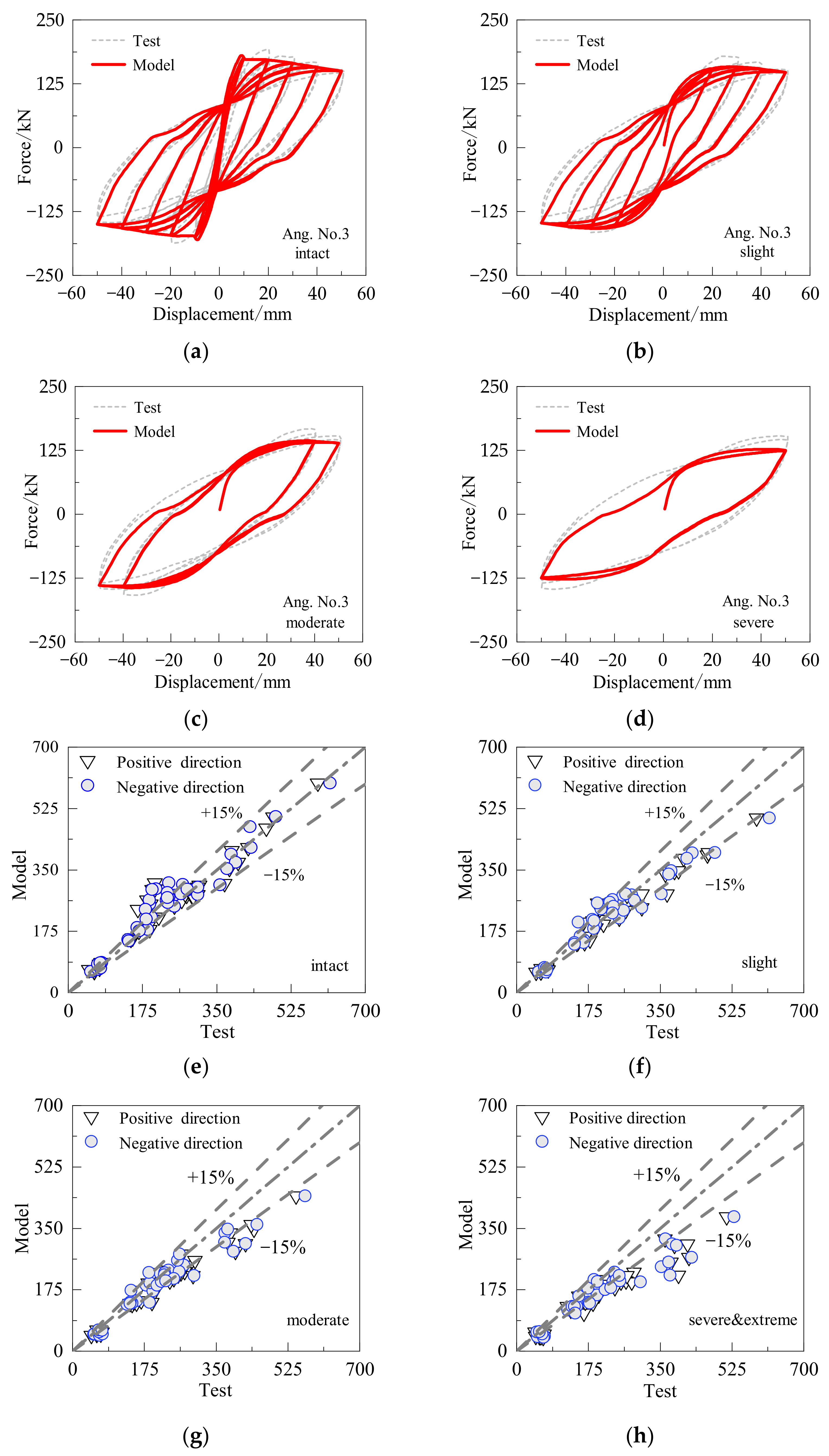
Then, substituting the damaged strain of materials into Equation (5) or (6), the residual strength of the damaged materials was obtained. After that, the numerical model for columns in different damage states could be developed. Examples of the residual load–displacement responses for Ang. No.3 are shown in Figure 5a–d, where the solid red line indicates the model results, and the dashed gray line represents the test results. According to the illustration, the model results for stiffness, residual bearing capacity, and hysteretic energy dissipation (shape of the hysteretic loops) of the specimen in intact, slight and moderate damage (Figure 5a–c) are in good agreement with the test results. In the condition of severe damage to the column (Figure 5d), the residual bearing capacity of model results is slightly lower than that of the test results, while the stiffness and hysteretic energy dissipation of the model results are generally consistent with the results of the experiment. Figure 5e–h shows a comparison between the model results and the test results of the residual bearing capacity of all the columns in different damage states. The model results are in good agreement with the test results, especially for columns with slight and moderate damage (Figure 5e,f). The prediction error of most columns in those two states is no greater than 15%. For columns with severe and extreme damage, the prediction error of some columns is slightly higher than 15%, whereas the overall coincidence degree is still acceptable.
In conclusion, the damage distribution model used in this paper can accurately predict the residual load–displacement responses of columns in different damage states. Therefore, it is reasonable to study the RSC of seismic damaged columns based on the damage distribution model.

3.3. Residual Collapse Capacity of Post-Earthquake Damaged Columns

The IDA method was performed on columns in different damage states, and then the collapse fragility curves of the damaged columns were obtained based on the method described in Section 2.4. The IDA curves of column Ang. No.3 in the extreme damage state subjected to the selected 21 ground motion records are shown in Figure 6a, which is used as an example to demonstrate the method of quantifying the residual collapse capacity of damaged columns. The ultimate drift ratio of the damaged column θu,d was determined according to the ultimate drift ratio θu of the undamaged columns. Generally, θu can be determined based on numerical analysis or test observation. However, it has been pointed out, in another work by the same authors [45], that the numerical model may not provide a sufficiently accurate simulation of the ultimate drift capacity of RC columns. Thus, θu shall be determined according to test data (shown in Table A1 in the Appendix A). The column is considered to be collapsed when θmax = θu,d, so the data when θmax > θu,d are not considered in the collapse fragility analysis of the damaged column.
Logarithm of the data when θmaxθu,d in Figure 6a was used to obtain ln(θmax) and ln(Sa(T1)), which were substituted into Equation (9) and finally fitted to obtain coefficients A and B, as shown in Figure 6b. Then, substituting the expression for ln(θmax) into Equation (8), the collapse fragility curve of the column Ang. No.3 in an extreme damage state was quantified.
Figure 7 depicts the collapse fragility curves of the column Ang. No.3 in intact, slight, moderate, severe, and extreme damage states in response to aftershocks. As shown in the figure, the collapse probability increases with the degree of mainshock-induced damage to the column at the same earthquake intensity. In other words, the capacity of the columns in aftershocks decreased with the increase in the damage that cumulated in mainshocks. Compared with the intact column, the earthquake intensity Sa(T1) corresponding to the 50% collapse probability decreased by 16%, 38%, 47%, and 56% for slightly, moderately, severely, and extremely damaged columns, respectively.
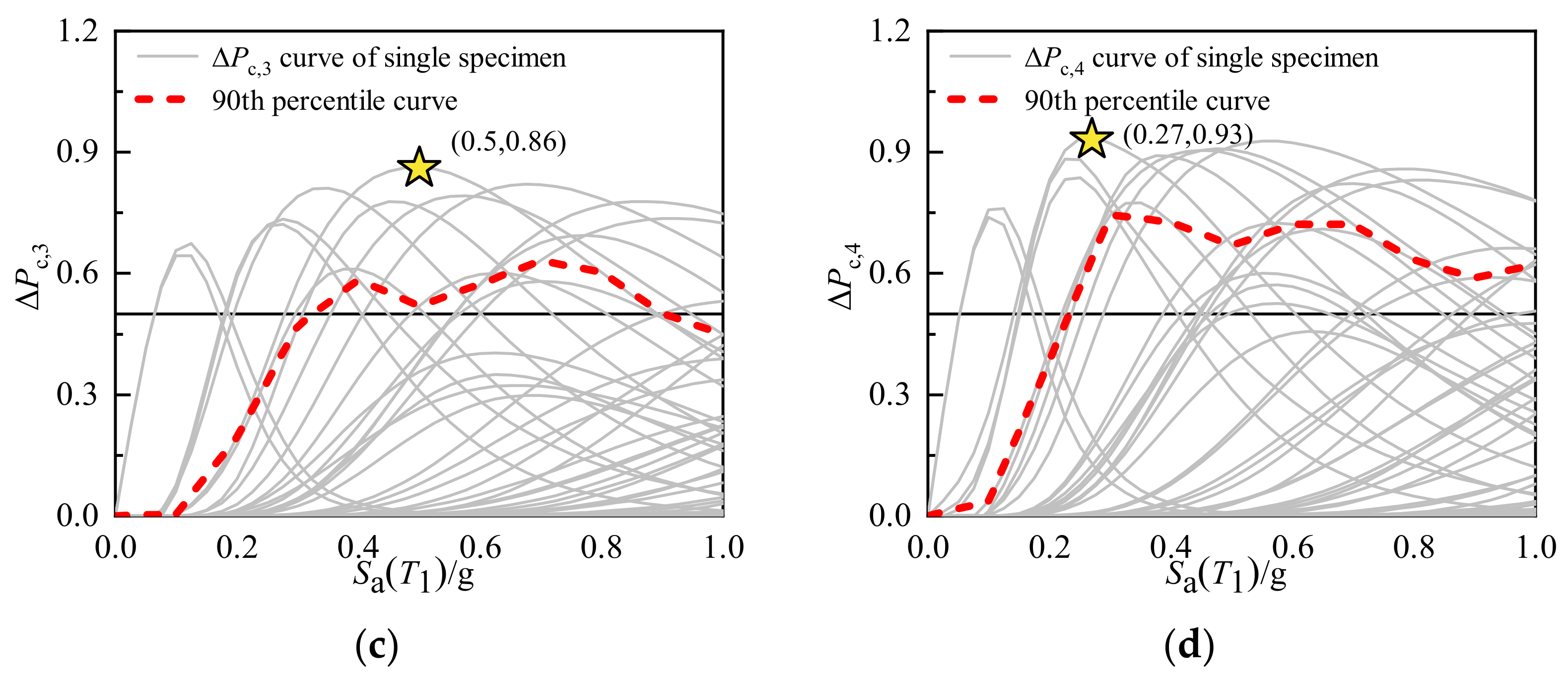
To further investigate the influence of mainshock-induced damage to columns on their residual collapse capacity in relation to aftershocks, the difference between the collapse probability of the columns in the intact state and that in the damaged state (denoted as ΔPc,i) was calculated. Here, subscript i in ΔPc,i denotes the i-th damage state of columns. The results of ΔPc,i are shown in Figure 8, where ΔPc,1, ΔPc,2, ΔPc,3, and ΔPc,4 represent the difference between the collapse probability of the columns in the intact state and that in slight, moderate, severe, and extreme damage, respectively. The solid gray lines in Figure 8 are the ΔPc,i curves of different columns. The magnitude of ΔPc,i reflects the likelihood of collapse during aftershocks. The column is very likely to collapse during aftershocks if ΔPc,i ≥ 50%. In Figure 8a–d, the maximum value of ΔPc,i is 60%, 67%, 86%, and 93%, respectively, indicating that the likelihood of collapse of the columns in aftershocks increases with the degree of mainshock-induced damage. In Figure 8a–d, the number of the columns of which ΔPc,i ≥ 50% is 3, 10, 16, and 23, respectively accounting for 7%, 24%, 39%, and 56% of the total number of columns. The more severe the mainshock-induced damage, the greater the proportion of the columns that collapse during aftershocks.
The red dotted lines in Figure 8 are the 90th percentile curves of ΔPc,i. As shown in Figure 8a, the 90th percentile curve of ΔPc,1 increases with the increase in earthquake intensity. In Figure 8a, the value of the 90th percentile curve of ΔPc,1 is always lower than 50%, indicating that 90% of the columns in the slight damage state do not collapse during the aftershocks. In Figure 8b, the increase rate of the 90th percentile curve of ΔPc,2 is significantly higher than that in Figure 8a. When the earthquake intensity is 0.9 g, the value is close to 50%, indicating that the columns in a moderate damage state tend to collapse under a high level of aftershock intensity (0.9 g). In Figure 8c,d, the 90th percentile curve of ΔPc,3 and ΔPc,4 showed a trend of decrease after an initial increase with increasing earthquake intensity. The ΔPc,i on the 90th percentile curves reaches 50% when the aftershock intensity is 0.3 g (in Figure 8c) and 0.24 g (in Figure 8d), indicating that columns in severe and extreme damage states tend to collapse at a low level of aftershock intensity.
The above results and analysis explain the effect of mainshock-induced damage to columns in terms of their residual capacity from the perspective of probability. Notably, the gray solid lines in Figure 8 vary, indicating that the collapse capacity of each column may be significantly different. As shown in Table A1 in the Appendix A, the structural parameters of the 41 columns, such as the axial ratio, traverse reinforcement ratio, and shear span ratio, are different. The collapse capacity of the columns in aftershocks is influenced not only by the mainshock-induced damage, but also by the structural parameters. In the following section, the effects of structural parameters were discussed.

4. Effect of Structural Parameters on Degradation of Collapse Capacity of Damaged Columns

The post-earthquake evaluation is usually required to be completed within a short period of time. Clearly, the investigation of a rapid evaluation method for the collapse capacity of damaged columns facilitates an enhanced efficiency of post-earthquake evaluation. In this section, the CFI of the damaged columns, which reflected the degradation of collapse capacity after mainshock, is calculated (Section 4.1) based on fragility curves. Then, a parametric study is conducted to analyze the correlation between structural parameters and degradation of collapse capacity (Section 4.2). Finally, an empirical model used to predict the degradation of residual collapse capacity of damaged columns is proposed according to the results of parameter study (Section 4.3), providing a reference for the rapid evaluation of the residual collapse capacity of RC structures after mainshocks.

4.1. Collapse Fragility Index of Damaged Columns

The level of ground motion intensity corresponding to 50% collapse probability is a frequently used indicator. Here, it was used to construct the CFI, which quantified the degradation of collapse capacity of RC columns after mainshocks. The expression of κ is as follows:
κ = S ^ a c o l , D M G S ^ a c o l , I N T
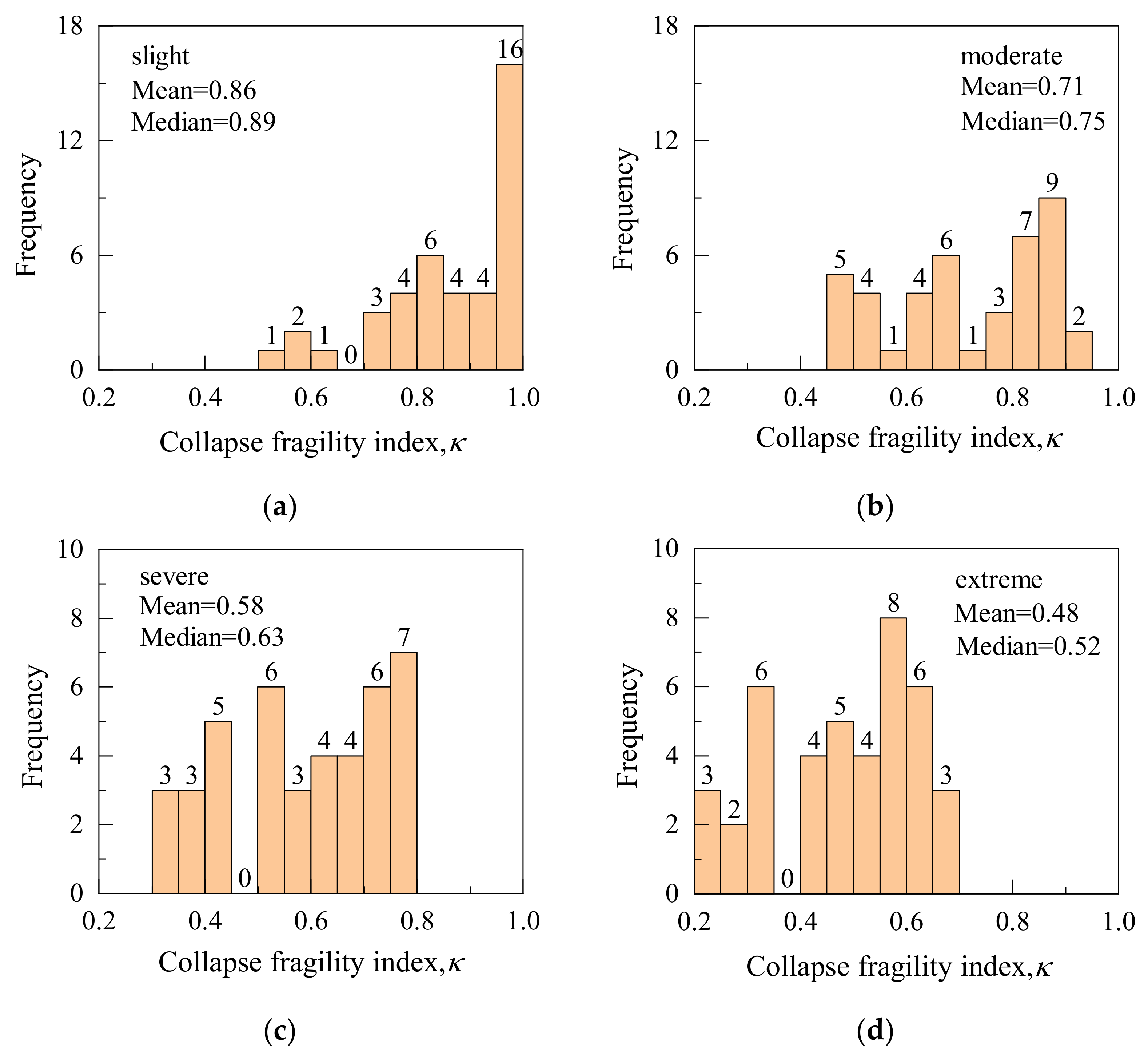
where  S ^ a c o l , I N T and  S ^ a c o l , D M G are, the Sa(T1) corresponding to the 50% collapse probability of RC columns in intact and damaged states, respectively. The lower the FCI, the more severe the degradation of the collapse capacity. If κ is close to one, the degradation of collapse capacity of the damaged column is not significant. The CFI can be calculated by combining the fragility curves of the columns for different damage states with Equation (10). For example, the ground motion intensities correspond to 50% collapse probability of Ang. No.3 specimen in intact state, and the slight, moderate, severe, and extreme damage states are, respectively, 0.86 g, 0.72 g, 0.56 g, 0.46 g, and 0.38 g. The CFI of the slightly, moderately, severely, and extremely damaged columns under the action of aftershock were 0.84, 0.65, 0.53 and 0.44, respectively. The frequency distribution of κ for all the selected 41 columns in different damage states is shown in Figure 9. As shown in Figure 9, the distribution of CFI gradually shifts to the left side of the coordinate axis as the degree of damage increases and the median and mean values gradually decrease. The median and mean values of κ decreased by 56% and 58% when the damage level increased from slight to extreme, respectively. An increase in the damage degree has a substantial impact on the degradation of the residual collapse capacity of the structure.

4.2. Structural Parameter Analysis

In this paper, six dimensionless structural parameters, namely the axial load ratio I1, volumetric stirrup ratio I2, ratio of confined concrete area to section area (Acor/A) I3, span-to-depth ratio I4, longitudinal reinforcement ratio I5, and stirrup spacing to section height ratio (s/h) I6, are selected to analyze their effects on the CFI of columns with different seismic damage states. The structural parameters are represented by Ii, subscript i in Ii denotes the i-th parameters. Figure 10 shows the distribution of structural parameters of each specimen. The first four plots show a more even distribution of the selected corresponding structural parameters. The distribution of parameters I5 and I6 is relatively concentrated. On the whole, the distribution of various structural parameters of the selected RC columns covered the common values in the existing studies and in engineering and could be used in the subsequent analysis.
Then, the correlation between the above six dimensionless structure parameters and the CFI was analyzed. The distribution of the CFI and the chosen structural parameters does not match the normal distribution, as seen in Figure 9 and Figure 10. Therefore, Spearman’s correlation coefficient r [46,47] with no variable distribution requirement was adopted as part of the correlation analysis. Generally, the correlation coefficient r has the following provisions: first, if the absolute value of the correlation coefficient |r| is greater than 0.5, this indicates that the characteristic parameter Ii is strongly correlated with κ. Second, when |r| is between 0.3 and 0.5, it is moderately correlated. Third, when |r| is between 0.1 and 0.3, it is weakly related. Lastly, |r| less than 0.1 indicates no correlation. Additionally, a significance test is required, since a correlation analysis alone cannot demonstrate that the link between structural characteristics Ii and the CFI is accurate.
First, we established the hypotheses (null hypothesis H0: Ii and κ are independent of each other; alternative hypothesis H1: Ii and κ are related), supposed that the test level α = 0.05, and then calculated the statistics. The p-value can be obtained by referencing the table according to statistics and sample numbers. If the p-value is smaller than the test level α, the null hypothesis should be rejected, and the alternative hypothesis should be accepted, leading to the conclusion that Ii is connected to κ. Otherwise, Ii and κ are independent of each other.
Table 2 shows the calculation results of Spearman correlation coefficients r and the p-value between structural parameters and CFI. As observed in Table 2, the axial load ratio under different damage states and the collapsed fragility index of the correlation coefficient absolute value |r| are greater than 0.5, explaining that the axial load ratio and κ have strong correlation. At the same time, the damage condition of the p-value is less than the α test level, which further proves the correlation. The correlation between κ and the structural parameters is depicted in Figure 11. Figure 11a demonstrates that κ decreases as the axial load ratio rises under various damage states.
In addition, the results shown in Table 2 show the state of a slight damage volume stirrup ratio I2 associated with κ medium (0.3 ≤ |r| ≤ 0.5, and p-value < α), but also that the other three damage states of the p-value were greater than α. Thus, a volume stirrup ratio I2 with α correlation has no statistical significance. In Figure 11b, it is difficult to observe the change rule of I2 related to κ, which further proves the results of correlation analysis. As one of the most important structural characteristic parameters, the volumetric stirrup ratio I2 affects many seismic performance indexes. For example, increasing I2 can significantly improve the ductility, deformation, and energy dissipation capacity of the structure, thus greatly improving the collapse capacity of the structure in the earthquake, but it is difficult to improve the aftershock fragility of the structure after the earthquake damage.
For the other structural parameters, as shown in Table 2, the corresponding correlation coefficients r of 0.1 indicate a very weak correlation, and the p-value is greater than 0.05, so these parameters show no correlation with κ. The scatter distributions shown in Figure 11c–f are further evidence that these parameters and the fragility index are not related to κ.

4.3. Establishment of Empirical Model

In this section, based on the discussion in Section 3.2, an empirical model is established on the basis of existing test data to study the evolution law of damage degree (damage index DI) and axial load ratio of CFI of earthquake-damaged structures. According to the discussion in Section 3.2, assume that the model form is as follows:
κ = 1 ( a + b n 0 ) D I
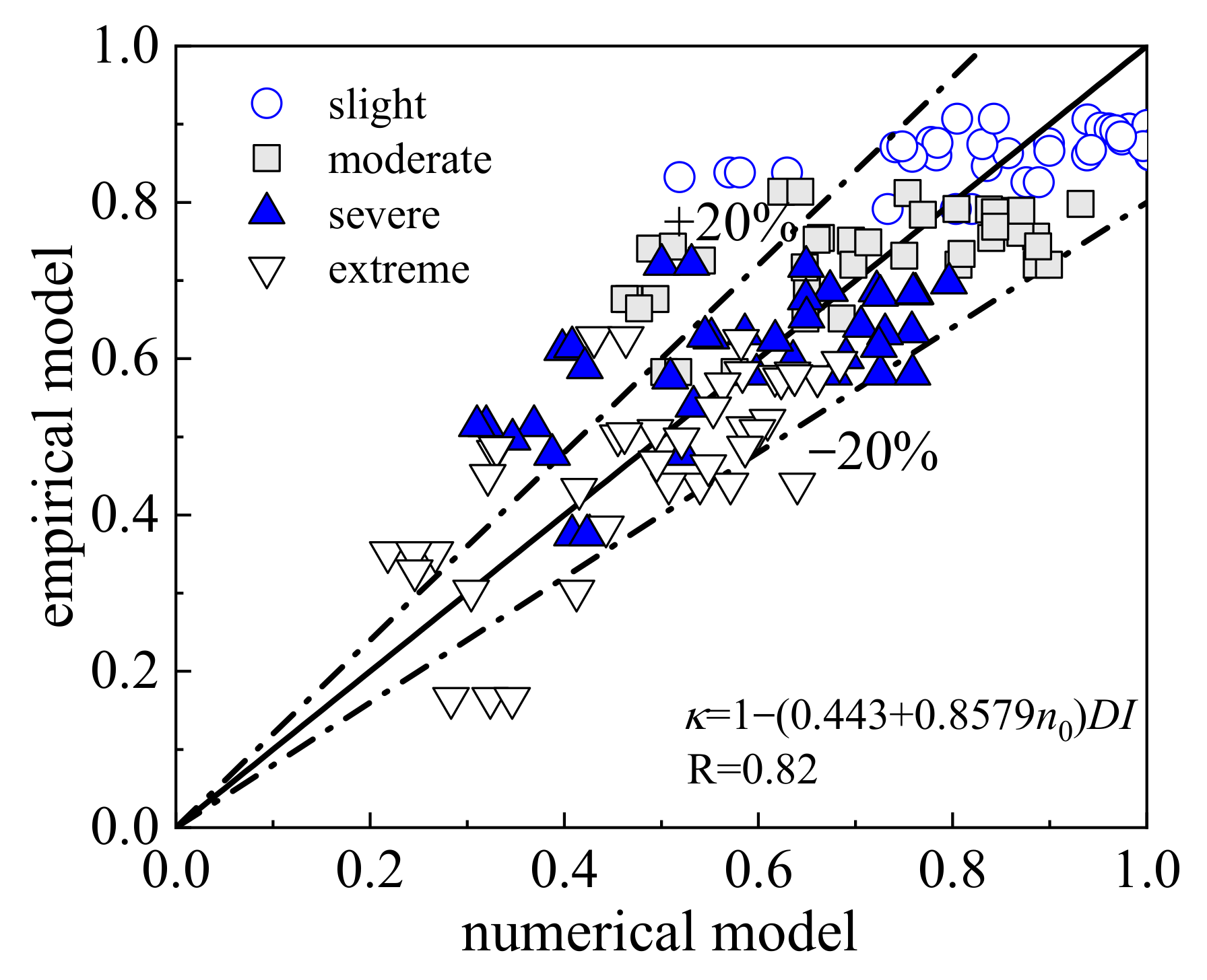
The coefficients a and b were 0.433 and 0.857, respectively. Figure 12 shows the comparison between the calculated value of κ obtained by Equation (11) and the numerical model simulation data. In Figure 12, the average errors of the fitted and simulated results for the slight, moderate, severe, and extreme damage states are 0.12, 0.14, 0.18, and 0.19, respectively. In slight, moderate, severe, and extreme damage states, the number of specimens with errors greater than 20% accounted for 9%, 22%, 29%, and 36% of the total specimens, respectively. It can be seen that, due to the decline of the prediction accuracy of the numerical model (Figure 5), the accuracy of the empirical model also shows a trend of decline with the increase in the damage degree, but the maximum error is still no greater than 20%. In general, the outcomes of the empirical model match the numerical model results well and can predict the degradation of the RSC of the damaged columns accurately.

5. Conclusions

In this study, based on the actual post-earthquake damage phenomenon, the uneven distribution of post-earthquake damage in columns was quantified using the damage distribution model. Then, a numerical analysis model of the earthquake damaged columns was established. Then, the numerical analysis model was used for IDA, simulating and evaluating the RSC of the post-earthquake damaged columns. The novelty of the proposed method is that the RSC of the column can be evaluated based on the actual post-earthquake damage phenomenon. Lastly, an empirical model was proposed for application in an actual post-earthquake rapid assessment. A number of conclusions can be drawn:
(1)
Based on the actual post-earthquake damage phenomenon and the damage distribution model, the simulation method of earthquake-damaged columns was suggested. Forty-one specimens were selected from the PEER database to verify the proposed numerical model. The results show that the proposed numerical model can accurately predict the residual load–displacement response of RC columns under different damage states.
(2)
Twenty-one ground motion records were selected for collapse fragility analysis of the numerical models of 41 specimens under different damage states. The fragility analysis results revealed that the higher the degree of main shock damage, the lower the residual collapse capacity. In addition, the 90% fractional line of the difference between aftershock collapse probability and main shock collapse probability of structures with different damage degrees was discussed. It is concluded that the RC column in the slightly damaged state has a 90% probability of not collapsing after aftershocks, and RC columns with moderate damage will collapse only under the action of strong aftershocks. For RC columns in severe and extremely damaged states, collapse will occur at low aftershock levels.
(3)
The CFI was calculated based on the fragility results. The mean values of the CFI for the slight, moderate, severe, and extreme damage states are 0.86, 0.71, 0.58, and 0.48, respectively. This shows that the risk of collapse of the structure increases significantly with the increase in the degree of damage. The two parameters with the greatest influence on the CFI were I1 and DI, as determined by parametric analysis. The empirical model of CFI related to I1 and DI is fitted. The fitted empirical model can effectively predict the degradation of the residual collapse capacity of damaged RC columns in different damage states (r = 0.82).
(4)
The method outlined in this paper can evaluate the RSC of columns based on the actual post-earthquake damage phenomenon. If the damage strain distribution of post-earthquake damaged columns can be quantified based on damage images and combined with computer vision and unmanned aerial vehicle technology, the efficiency of the evaluators can be greatly improved.

Author Contributions

Conceptualization, L.L.; methodology, J.C.; software, W.W. and J.C.; formal analysis, J.C.; data curation, J.C.; writing—original draft preparation, J.C. and L.L.; writing—review and editing, L.L. and W.W.; project administration, L.L.; funding acquisition, L.L. All authors have read and agreed to the published version of the manuscript.

Funding

This work is founded by the National Natural Science Foundation of China (Grant Number:52278531) and the Independent Research and Development project of the State Key Laboratory of Green Building in Western China (Project Number: LSZZ202226).

Data Availability Statement

The data reported in this article are available from the corresponding author upon request.

Conflicts of Interest

The authors declare no conflict of interest.

Appendix A. Parameters of Test Specimen Used in this Research (Table A1)

Table A1. Parameters of test specimen used in this research.
Specimenb
(mm)
h
(mm)
H
(mm)
c
(mm)
d1
(mm)
d2
(mm)
fc
(Mpa)
fy
(Mpa)
fyv
(Mpa)
n0
(%)
rv
(%)
θu
(%)
Ang. No.3400400160024.5161223.64273200.382.83.12
Ang. No.4400400160022.51610254272800.212.23.62
Soes. No.140040016001316746.54463640.10.96.25
Soes. No.2400400160013168444463600.31.25.3
Soes. No.3400400160013167444463640.30.82.8
Soes. No.4400400160013166404462550.30.62.8
Watson. No.5400400160013168414743720.50.72.5
Watson. No.6400400160013166404743880.50.31.5
Watson. No.74004001600131612424743080.71.31.12
Watson. No.8400400160013168394743720.70.71.12
Watson. No.94004001600131612404743080.72.32.68
Tanaka. No.1400400160040201225.64743330.22.53.5
Tanaka. No.55505501650402012325113250.11.76
Tanaka. No.7550550165040201232.15113250.32.15
Ohno. L3400400160031.519924.83623250.0320.34.6
Atalay. No.1S1305305167632229.529.13673630.0991.86
Atalay. No.2S1305305167632229.530.73673630.0931.54.8
Atalay. No.4S1305305167632229.527.64293630.1040.95.3
Atalay. No.5S1305305167632229.529.44293920.1950.96
Atalay. No.6S1305305167632229.531.84293920.1811.54.8
Atalay. No.9305305167632229.533.33633920.2590.93.03
Atalay. No.10305305167632229.532.43633920.2661.53.03
Azizinamini. NC-2457457137238.125.412.739.34394540.2060.94.7
Azizinamini. NC-4457457137241.325.49.539.84396160.312.22.9
Wehbe. A138061023352819.1627.24484280.0981.95.2
Wehbe. A238061023352819.1627.24484280.2390.45.2
Wehbe. B138061023352519.1628.14484280.0920.46.85
Wehbe. B238061023352519.1628.14484280.2320.54.83
Lynn. 2CLH18457.2457.2147338.125.49.533.13312990.0730.52
Lynn. 2CMH18457.2457.2147338.125.49.525.53313990.2840.21
Saatcioglu. BG-135035016452919.59.534455.65700.4280.23.04
Saatcioglu. BG-235035016452919.59.534455.65700.42815
Saatcioglu. BG-335035016452919.59.534455.65700.227
Saatcioglu. BG-435035016452919.59.534455.65700.46224.86
Saatcioglu. BG-535035016452919.59.634455.65700.4621.36
Saatcioglu. BG-835035016452919.56.634455.65800.2312.77
Mo. C1–1400400140034196.324.94974590.1131.36.3
Mo. C1–2400400140034196.326.74974590.1581.56.7
Mo. C1–3400400140034196.326.14974590.2161.56.65
Takemura. Test1400400124527.512.7635.93633680.0271.53.5
Takemura. Test2400400124527.512.7635.73633680.0270.55.6

References

  1. Applied Technology Council. ATC-20 Procedures for Post-Earthquake Building Safety Evaluation Procedures; Applied Technology Council (ATC): Redwood City, CA, USA, 1995. [Google Scholar]
  2. GB/T 24335−2009; Classification of Earthquake Damaged Buildings and Special Structures. Standards Press of China: Beijing, China, 2009.
  3. Mitrani-Resier, J.; Wu, S.; Beck, J.L. Virtual inspector and its application to immediate pre-event and post-event earthquake loss and safety assessment of buildings. Nat. Hazards 2016, 81, 1861–1878. [Google Scholar] [CrossRef]
  4. Anagnostopoulos, S.; Moretti, M. Post-earthquake emergency assessment of building damage, safety and usability—Part 1: Technical issues. Soil Dyn. Earthq. Eng. 2008, 28, 223–232. [Google Scholar] [CrossRef]
  5. Cheng, B.; Chang, R.; Yin, Q.; Li, J.; Huang, J.; Chen, H. A PSR-AHP-GE model for evaluating environmental impacts of spoil disposal areas in high-speed railway engineering. J. Clean. Prod. 2023, 388, 135970. [Google Scholar] [CrossRef]
  6. Qu, B.W.; Zhang, H.Y.; Mao, C.X. Quantitative seismic damage assessment method for reinforced concrete frame column. Word Earthq. Eng. 2018, 34, 85–93. [Google Scholar]
  7. Fu, H.; Niu, J.; Wu, Z.; Cheng, B.; Guo, X.; Zuo, J. Exploration of public stereotypes of supply-and-demand characteristics of recycled water infrastructureEvidence from an event-related potential experiment in Xi’an, China. J. Environ. Manag. 2022, 322, 116103. [Google Scholar] [CrossRef]
  8. Valente, M.; Milani, G. Alternative retrofitting strategies to prevent the failure of an under-designed reinforced concrete frame. Eng. Fail. Anal. 2018, 89, 271–285. [Google Scholar] [CrossRef]
  9. Valente, M.; Milani, G. Advanced numerical insights into failure analysis and strengthening of monumental masonry churches under seismic actions. Eng. Fail. Anal. 2019, 103, 410–430. [Google Scholar] [CrossRef]
  10. Valente, M.; Barbieri, G.; Biolzi, L. Seismic assessment of two masonry Baroque churches damaged by the 2012 Emilia earthquake. Eng. Fail. Anal. 2017, 79, 773–802. [Google Scholar] [CrossRef]
  11. Miao, Z.; Ji, X.; Wu, M.; Gao, X. Deep learning-based evaluation for mechanical property degradation of seismically damaged RC columns. Earthq. Eng. Struct. Dyn. 2022, 1–22. [Google Scholar] [CrossRef]
  12. FEMA 306; Evaluation of Earthquake Damaged Concrete and Masonry Wall Buildings: Basic Procedures557 Manual. Federal Emergency Management Agency: Washington, DC, USA, 1998.
  13. Trevlopoulos, K.; Gueguen, P. Period elongation-based framework for operative assessment of the variation of seismic vulnerability of reinforced concrete buildings during aftershock sequences. Soil Dyn. Earthq. Eng. 2016, 84, 224–237. [Google Scholar] [CrossRef]
  14. Burton, H.V.; Deierlein, G.G. Integrating visual damage simulation, virtual inspection, and collapse capacity to evaluate post-earthquake structural safety of buildings. Earthq. Eng. Struct. Dyn. 2018, 47, 294–310. [Google Scholar] [CrossRef]
  15. Shokrabadi, M.; Burton, H.V. Risk-based assessment of aftershock and mainshock-aftershock seismic performance of reinforced concrete frames. Struct. Saf. 2018, 73, 64–74. [Google Scholar] [CrossRef]
  16. Abdelnaby, A.E. Fragility curves for RC frames subjected to Tohoku mainshock-aftershocks sequences. J. Earthq. Eng. 2018, 22, 902–920. [Google Scholar] [CrossRef]
  17. Raghunandan, M.; Liel, A.B.; Luco, N. Aftershock collapse vulnerability assessment of reinforced concrete frame structures. Earthq. Eng. Struct. Dyn. 2015, 44, 419–439. [Google Scholar] [CrossRef]
  18. Di Trapani, F.; Malavisi, M. Seismic fragility assessment of infilled frames subject to mainshock/aftershock sequences using a double incremental dynamic analysis approach. Bull. Earthq. Eng. 2019, 17, 211–235. [Google Scholar] [CrossRef]
  19. Iervolino, I.; Chioccarelli, E.; Suzuki, A. Seismic damage accumulation in multiple mainshock–aftershock sequences. Earthq. Eng. Struct. Dyn. 2020, 49, 1007–1027. [Google Scholar] [CrossRef]
  20. Furtado, A.; Rodrigues, H.; Varum, H.; Arêde, A. Mainshock-aftershock damage assessment of infilled RC structures. Eng. Struct. 2018, 175, 645–660. [Google Scholar] [CrossRef]
  21. Lu, X.; Cheng, Q.; Xu, Z.; Xiong, C. Regional seismic-damage prediction of buildings under mainshock-aftershock sequence. Front. Eng. Manag. 2021, 8, 122–134. [Google Scholar] [CrossRef]
  22. Liao, W.; Fei, Y.; Ghahari, F.; Zhang, W.; Chen, P.Y.; Kurtulus, A.; Yen, C.H.; Cheng, Q.; Lu, X.; Taciroglu, E. Influence of accelerometer type on uncertainties in recorded ground motions and seismic damage assessment. Bull. Earthq. Eng. 2022, 20, 4419–4439. [Google Scholar] [CrossRef]
  23. FEMA-P695; Quantification of Building Seismic Performance Factors. Applied Technology Council; Federal Emergency Management Agency: Washington DC, USA, 2009.
  24. Shafei, B.; Zareian, F.; Lignos, D. A simplified method for collapse capacity assessment of moment-resisting frame and shear wall structural systems. Eng. Struct. 2011, 33, 1107–1116. [Google Scholar] [CrossRef]
  25. Park, Y.J.; Ang, A.H. Mechanistic seismic damage model for reinforced concrete. J. Struct. Eng. 1985, 4, 722–739. [Google Scholar] [CrossRef]
  26. Li, L.; Luo, G.X.; Wang, Z.H.; Zhang, Y.X.; Zhuge, Y. Prediction of residual behaviour for post-earthquake damaged reinforced concrete column based on damage distribution model. Eng. Struct. 2021, 234, 111927. [Google Scholar] [CrossRef]
  27. Kent, D.C.; Park, R. Flexural members with confined concrete. J. Struct. Div. 1971, 97, 1969–1990. [Google Scholar] [CrossRef]
  28. Mander, J.B.; Priestley, M.J.N.; Park, R. Theoretical stress–strain model for confined concrete. J. Struct. Eng. 1988, 114, 1804–1826. [Google Scholar] [CrossRef] [Green Version]
  29. Feng, D.C.; Cao, X.Y.; Wang, D.; Wu, G. A PDEM-based non-parametric seismic fragility assessment method for RC structures under non-stationary ground motions. J. Build. Eng. 2023, 63, 105465. [Google Scholar] [CrossRef]
  30. Zhou, Y.; Chen, L.Z.; Long, L. Modeling cyclic behavior of squat reinforced concrete walls exposed to acid deposition. J. Build. Eng. 2023, 63, 105432. [Google Scholar] [CrossRef]
  31. ASCE/SEI 41-13; Seismic Evaluation and Retrofit of Existing Buildings. Engineers AmS O C: Reston, VI, USA, 2014.
  32. Melchers, R.E. Structural Reliability: Analysis and Prediction, 2nd ed.; John Wiley & Sons: New York, NY, USA, 1999. [Google Scholar]
  33. Ang, B.G.; Priestley, M.J.N.; Park, N. Ductility of Reinforced Bridge Piers under Seismic Loading. Master’s Thesis, University of Canterbury, Canterbury, New Zealand, 1981. [Google Scholar] [CrossRef]
  34. Soesianawati, M.T. Limited Ductility Design of Reinforced Concrete Columns. Master’s Thesis, University of Canterbury, Canterbury, New Zealand, 1986. [Google Scholar] [CrossRef]
  35. Watson, S. Design of Reinforced Concrete Frames of Limited Ductility. Ph.D. Thesis, University of Canterbury, Canterbury, New Zealand, 1989. [Google Scholar] [CrossRef]
  36. Tanaka, H. Effect of Lateral Confining Reinforcement on the Ductile Behaviour of Reinforced Concrete Columns. Ph.D. Thesis, University of Canterbury, Canterbury, New Zealand, 1990. [Google Scholar] [CrossRef]
  37. Ohno, T.; Nishioka, Y. An Experimental Study on Energy Absorption Capacity of Columns in Reinforced Concrete Structures. Doboku Gakkai Ronbunshu 1984, 1984, 23–33. [Google Scholar] [CrossRef] [Green Version]
  38. Atalay, M.B.; Penzien, J. The Seismic Behavior of Critical Regions of Reinforced Concrete Components as Influenced by Moment, Shear and Axial Force; Earthquake Engineering Research Center, University of California: Berkeley, CA, USA, 1975. [Google Scholar]
  39. Azizinamini, A.; Corley, W.G.; Johal, L.P. Effects of Transverse Reinforcement on Seismic Performance of Columns. Aci Struct. J. 1992, 89, 442–450. [Google Scholar] [CrossRef]
  40. Wehbe, N. EERI Annual Student Paper Award Confinement of Rectangular Bridge Columns in Moderate Seismic Areas. Earthq. Spectra 1998, 14, 397–406. [Google Scholar] [CrossRef]
  41. Lynn, A.C.; Moehle, J.P.; Mahin, S.A.; Holmes, W.T. Seismic Evaluation of Existing Reinforced Concrete Building Columns. Earthq. Spectra 1996, 12, 715–739. [Google Scholar] [CrossRef]
  42. Saatcioglu, M.; Grira, M. Confinement of Reinforced Concrete Columns with Welded Reinforced Grids. Aci Struct. J. 1999, 96, 29–39. [Google Scholar] [CrossRef]
  43. Mo, Y.L.; Wang, S.J. Seismic Behavior of RC Columns with Various Tie Configurations. J. Struct. Eng. 2000, 126, 1122–1130. [Google Scholar] [CrossRef]
  44. Takemura, H.; Kawashima, K. Effect of loading hysteresis on ductility capacity of reinforced concrete bridge piers. J. Struct. Eng. 1997, 43, 849–858. [Google Scholar]
  45. Li, L.; Wang, W.T.; Shi, P.P. Modelling catastrophic degradation of flexural-dominated RC columns at ultimate displacements based on fibre beam-column model. J. Build. Eng. 2022, 45, 103476. [Google Scholar] [CrossRef]
  46. Genest, C.; Favre, A.C. Everything you always wanted to know about copula modeling but were afraid to ask. J. Hydrol. Eng. 2007, 12, 347–368. [Google Scholar] [CrossRef]
  47. Cheng, B.; Fu, H.; Li, T. Evolutionary computation-based multitask learning network for railway passenger comfort evaluation from EEG signals. Appl. Soft Comput. 2023, 136, 110079. [Google Scholar] [CrossRef]
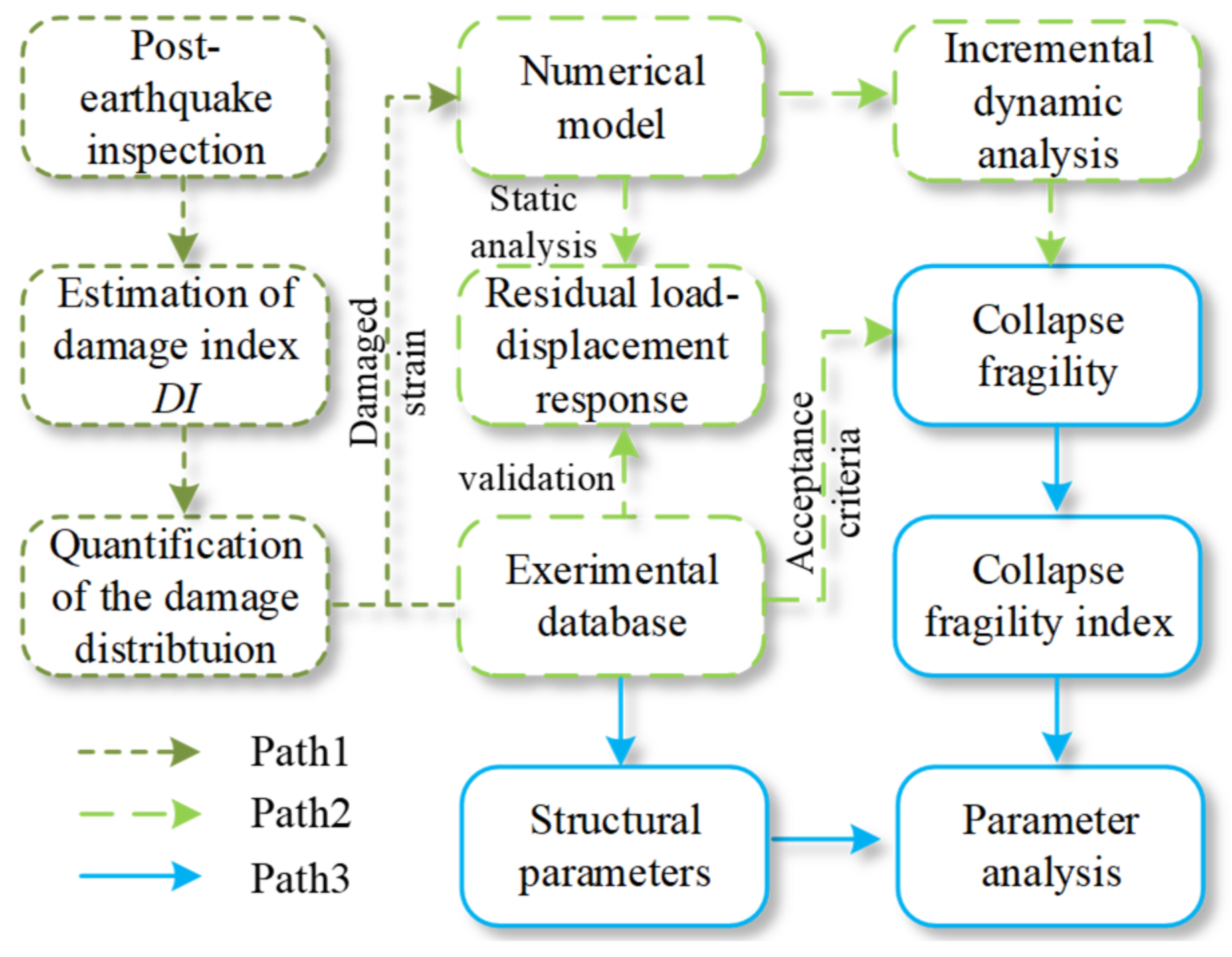
Figure 1. Overview of the methodology.
Buildings 13 00595 g001
Figure 2. Schematic showing the material location.
Buildings 13 00595 g002
Figure 3. Schematic diagram of the IDA curve and spectral acceleration response of the selected ground motions. (a) Schematic diagram of the IDA curve; (b) Spectral acceleration response of the selected ground motions.
Buildings 13 00595 g003
Figure 4. The collapse point of the RC column.
Buildings 13 00595 g004
Figure 5. The residual load–displacement response of the seismic damage column Ang. No.3 and the residual bearing capacity of all the columns in different damage degree. (a) Response in the intact state. (b) Response in the slight damage state. (c) Response in the moderate damage state. (d) Response in the severe damage state. (e) The residual bearing capacity in the intact state. (f) The residual bearing capacity in the slight damage state. (g) The residual bearing capacity in the moderate damage state. (h) The residual bearing capacity in the severe and extreme damage state.
Buildings 13 00595 g005
Figure 6. IDA curves and regression analysis of the results. (a) The IDA curves of column Ang. No.3 in the extreme damage state. (b) Regression analysis based on IDA results.
Buildings 13 00595 g006
Figure 7. Collapse fragility curves of columns with different damage states.
Buildings 13 00595 g007
Figure 8. Results of ΔPc,i for damaged column of different initial damage level. (a) Results of ΔPc,1. (b) Results of ΔPc,2. (c) Results of ΔPc,3. (d) Results of ΔPc,4.
Buildings 13 00595 g008aBuildings 13 00595 g008b
Figure 9. Frequency distribution of collapse fragility index of column specimen under different damage degrees. (a) Under the slight damage state. (b) Under the moderate damage state. (c) Under the severe damage state. (d) Under the extreme damage state.
Buildings 13 00595 g009
Figure 10. The frequency distribution of the structural parameters. (a) The axial load ratio I1. (b) The volumetric stirrup ratio I2. (c) The ratio of confined concrete area to section area I3. (d) The span-to-depth ratio I4. (e) The longitudinal reinforcement ratio I5. (f) The stirrup spacing to section height ratio I6.
Buildings 13 00595 g010
Figure 11. Distribution of collapse fragility index corresponding to each structural characteristic parameter under different damage states. (black square: slight damage state; grey circle: moderate damage state; blue triangle: severe damage state; white inverted triangle: extreme damage state).
Buildings 13 00595 g011aBuildings 13 00595 g011b
Figure 12. Comparison between predicted value of empirical model and value of numerical model.
Buildings 13 00595 g012
Table 1. The damaged strain of extreme fibers of confined concrete in the RC specimen.
Ref.Specimenεcc,d (%)εccu (%)
Slight DamageModerate DamageSevere DamageExtreme Damage
[33]Ang. No.31.243.5114.8884.17.67
Ang. No.40.952.6711.3364.035.6
[34]Soes. No.10.541.526.4336.312.64
Soes. No.20.661.887.9544.913.53
Soes. No.30.541.526.4336.312.62
Soes. No.40.421.25.0728.671.7
[35]Watson. No.50.691.968.2946.833.68
Watson. No.60.481.365.7532.492.27
Watson. No.70.852.3910.1557.345
Watson. No.80.732.088.7949.693.3
Watson. No.91.43.9516.7494.617.42
[36]Tanaka. No.11.243.5114.8884.17.58
Tanaka. No.50.852.3910.1557.344.84
Tanaka. No.70.972.7511.6765.943.3
[37]Ohno. L30.571.66.7738.232.9
[38]Atalay. No.1S10.782.199.352.563.41
Atalay. No.2S10.511.446.0934.42.38
Atalay. No.4S10.541.526.4336.312.57
Atalay. No.5S10.812.279.6454.473.57
Atalay. No.6S10.521.486.2635.362.45
Atalay. No.90.752.128.9650.653.28
Atalay. No.100.511.446.0934.42.42
[39]Azizinamini. NC-21.022.8712.1868.814.02
Azizinamini. NC-40.862.4310.3258.292.05
[40]Wehbe. A10.481.365.7532.491.84
Wehbe. A20.481.365.7532.491.84
Wehbe. B10.541.526.4336.312.15
Wehbe. B20.541.526.4336.312.15
[41]Lynn. 2CLH180.30.843.5520.070.94
Lynn. 2CMH180.30.843.5520.071.1
[42]Saatcioglu. BG-10.651.847.7843.963.07
Saatcioglu. BG-21.193.3514.2180.274.5
Saatcioglu. BG-31.193.3514.2180.274.5
Saatcioglu. BG-40.792.239.4753.523.7
Saatcioglu. BG-51.474.1517.5999.395.28
Saatcioglu. BG-80.952.6711.3364.033.41
[43]Mo. C1–11.193.3514.2180.273.95
Mo. C1–21.133.1913.5376.453.78
Mo. C1–31.133.1913.5376.453.78
[44]Takemura. Test10.451.285.4130.581.28
Takemura. Test20.451.285.4130.581.28
Table 2. Calculation results of correlation coefficient and p-value.
Structural ParametersSlight DamageModerate DamageSevere DamageExtreme Damage
rp-Valuerp-Valuerp-Valuerp-Value
I1−0.5320.000−0.5290.000−0.6140.000−0.6990.000
I2−0.3760.015−0.2670.091−0.2220.162−0.3000.056
I3−0.0340.834−0.1020.524−0.1200.455−0.0880.584
I40.1350.4000.1310.4140.1190.4570.0650.689
I50.0320.844−0.0770.632−0.1300.418−0.1280.423
I60.1310.4140.1110.4890.1070.5070.0570.722
Disclaimer/Publisher’s Note: The statements, opinions and data contained in all publications are solely those of the individual author(s) and contributor(s) and not of MDPI and/or the editor(s). MDPI and/or the editor(s) disclaim responsibility for any injury to people or property resulting from any ideas, methods, instructions or products referred to in the content.