Article

Prestressed Steel-Concrete Composite I-Beams with Single and Double Corrugated Web

1
Engineering Management Department, College of Engineering, Prince Sultan University, Riyadh 11586, Saudi Arabia
2
Structural Engineering Department, Zagazig University, Zagazig 44519, Egypt
3
Department of Engineering and Technology, Texas A&M University-Commerce, Commerce, TX 75429, USA
4
Housing and Building National Research Center, Giza 12622, Egypt
*
Author to whom correspondence should be addressed.
Buildings 2023, 13(3), 647; https://doi.org/10.3390/buildings13030647
Submission received: 7 February 2023 / Revised: 25 February 2023 / Accepted: 25 February 2023 / Published: 28 February 2023
(This article belongs to the Special Issue Steel-Concrete Composite Structures: Design and Construction)

Abstract

:
Composite steel girders with concrete have been used for many years and advances in structural and fabrication technology have established their optimization. One of the changes in structural steel I-beams during the past few years has been the availability of web corrugation. The economic design of steel girders normally requires thin webs. Moreover, using externally prestressed tendons as a strengthening technique controls deflections and stresses. However, this strengthening technique causes shear buckling of the steel beams. In this study, the flexural behavior of externally prestressed composite steel-concrete I-beams with a single and double corrugated web was experimentally and numerically investigated. Three simply supported prestressed steel-concrete composite I-beams with single corrugated web (SCW) and double corrugated web (DCW) were tested under four-point loading. The tested beams were externally prestressed by using straight tendons along the full length. The experimental results showed that using SCW was more efficient in shear buckling resistance than DCW with the same equivalent web thickness. The ABAQUAS package was used to simulate the nonlinear behavior of the tested beams. The developed model was validated against the experimental results to carry out a parametric study in order to investigate the effect of various parameters on the behavior of the composite beams with SCW and DCW. Using stiffeners at the loading points as deviators to maintain the prestressed tendon positions increased the beam capacity and improved the beam performance.

1. Introduction

Steel-concrete composite beams present a popular and economical form of construction in both buildings and bridges. Advances in structural and fabrication technology have established the optimization of steel girders. The idea of using corrugated webs in steel structures to increase buckling resistance was first tried out as early as 1924, but due to difficulties in fabrication, its use was limited until further technical development [1,2]. As part of a national French project, a search for lighter and stronger girders took place, which could be achieved by external prestressing and corrugated web (CW). A large-scale test model was built by Campenon Bernard in 1983 and was externally prestressed. Afterwards, they built the first ever corrugated steel web bridge, Cognac Bridge, which was constructed in France between June 1985 and July 1986 [2,3]. Many advantages can be gained from using external prestressing [4]. Prestressing can increase the beam capacity and reduce the serviceability deflection. It can also improve the behavior of the beam against fatigue and increase the elastic behavior zone. The first ever corrugated steel-built web bridge was the Cognac Bridge, constructed in France between June 1985 and July 1986 [2,3,5]. The Maupre Bridge was the second bridge built with a corrugated steel web [2].
It is well known in the literature that flat steel web (FW) is widely used for composite beams. For instance, Ayyub et al. [4] tested three prestressed composite beams under a positive bending moment. They concluded that adding prestressing to beams could reduce the mid-span deflection and increase the elastic behavior regime and the ultimate load capacity. They also found that the use of the straight tendon profile with saddle points is more efficient than that of the draped tendon profile. Chen and Gu [6,7] studied prestressed composite beams under negative and positive moments and found that, in negative moment regions, the cracking resistance of the beams can increase, but the yield moment does not always increase. In contrast, positive moment regions showed a significant increase in yield and ultimate load. Lorenc and Kubica [8] tested six simply supported prestressed and non-prestressed composite beams with straight and draped tendon profiles under the sagging moment. It was found that the tendon profile had no significant effect on the beam resistance. El-Zohairy and Salim [9,10] studied numerically the composite beams at sagging moment regions. The study found that the trapezoidal profile shape shows better behavior than the straight tendon, which shows more ductile behavior at the same level of eccentricity. Prestressing the beam using a full-length tendon can reduce the formation of fatigue cracks and a partial degree of composite action greater than 80% is recommended to obtain the desired performance in prestressing. El-Zohairy et al. [11] developed FEM to simulate the behavior of continuous prestressed composite beams at hogging moment regions. The FEM was validated with existing laboratory tests. They found that the beam capacity increases by about 8% and the cracked moment redoubles. El-Zohairy et al. [12] tested four composite beams to assess the effect of externally prestressed tendons on fatigue behavior and beam capacity. They found that the prestressed tendon could decrease the strain of the beam elements at all stages of loading, which leads to improved beam performance under fatigue. Da Rocha Almeida et al. [13] tested two prestressed and non-prestressed composite beams with profiled steel decking under two points of loading. The test ended before its failure because of the excessive deformations of the models and safety fears. They developed FE models to simulate the behavior of the tested beam and found that the failure mechanism was the yielding of structural steel beams in tension, and that adding prestressing force to the beams can increase the maximum moment by up to 19%. A parametric analysis on an external prestressed composite beam was conducted by Da Rocha Almeida et al. [14]. An analytical model using plastic moment analysis and a numerical FE model was used in this study after vitrification in previous tests. They found that the analytical model results are comparable with the FE model and the position of a shorter tendon in a pure moment region is less efficient than the full and moderate tendon length.
Comparing CW with FW, the CW has the following advantages [2,15,16]; adequate out-of-plane stiffness, high in-plane shear force resistance with narrow-spaced folds, stiffeners elimination, less weigh and economical beams. Therefore, several case studies were proposed to accurately study the effect of the external prestressing on the different types of steel concrete composite I-beams. For example, five prestressed girders with a span of 5.5 m, fabricated with prestressed concrete bottom flanges, reinforced concrete top flanges, and zigzag corrugated steel webs, were tested on two points of load by [17]. They concluded that no post-buckling will be shown when the web reaches shear yield strength. The tested girder showed high deflection recovery because of its ductility. Three full-scaled composite beams were tested by Kim and Lee [18], who found that the steel beam with CW was able to introduce larger prestress into the top and bottom flanges, compared with the typical I-shaped steel beam, because of the accordion effect. Based on numerical analyses, Kim et al. [19] used the concept of the effective moment of inertia (Ieff) and the effective sectional area (Aeff) to obtain the section stress and strain of a prestressed composite beam with CW. By using the coefficient of the effective moment of inertia (ηf) and the coefficient of effective web area (ηa), a very accurate estimation of the accordion effect and of flexural behavior can be achieved. They also found that the flexural strength and stiffness of the prestressed composite beams increased by about 20% to 25% compared with the non-prestressed. Lee et al. [20] studied two new specimens to investigate the effect of the welding method and concluded that the use of partial welding can reduce time and cost and give the required performance, compared with gross welding. Xu, Zhang [21] investigate the reliability of the ABAQUS finite element model that was used to simulate the external prestressed concrete composite beam with CW after its verification in the work of Song, Zhang [22], who found that the consideration of secondary effects for externally prestressed tendons in the calculation is irrational. Motlagh and Rahai investigated numerically the long-term losses of prestressed composite beams with CW. Decreasing the corrugation depth could decrease the prestressing losses [23]. The structural performance and cost-effectiveness of a composite beam with CSW for an extradosed cable-stayed bridge were investigated [24]. Three different prestressed steel–concrete composite beams with corrugated web were investigated experimentally and numerically by Zhou et al. [25] under fire conditions, the first beam without encased web, the second encased with concrete from one side, and the third encased on two sides. The failure of the first beam was the buckling of the web. The beam with one-sided concrete between the flanges experienced horizontal deflection, and shear centers move in the direction of the coldest side of the web. Numerical analyses showed that the failure appears to have been caused by cable strands rupturing inside of concrete enclosure.
An overview of the different contributions of different types of prestressed composite steel-concrete I-beams that have been investigated in the literature is presented in Table 1.
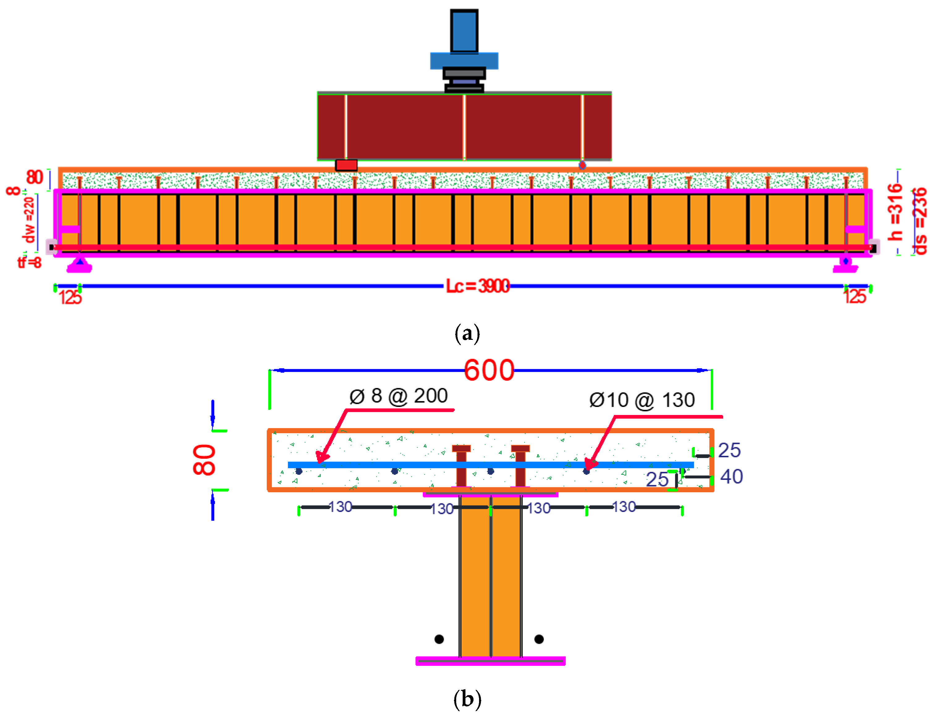
In light of the previous discussion, ample research has been focused on the use of composite flat web beams and their behavior under external prestressing, but utilizing corrugated web in buildings and bridges has also increased in recent years. There is also an urgent need to strengthen these types of beams, which can be achieved by using external prestressing. A small amount of research has been conducted on the full and partially encased prestressed I-beam with CW, based on information available to the authors. Additionally, no studies have investigated the behavior of the externally prestressed steel I-beam with a single or double corrugated web. Therefore, the flexural behavior of externally prestressed composite steel-concrete I-beams with a single and double corrugated web was experimentally and numerically investigated in this paper. Three simply supported prestressed steel-concrete composite I-beams with single corrugated web (SCW) and double corrugated web (DCW) were tested under four-point loading. The tested beams were externally prestressed by using straight tendons along the full length. The ABAQUAS package was used to simulate the nonlinear behavior of the tested beams. The developed model was validated against experimental results to carry out a parametric study to investigate the effect of various parameters on the behavior of the composite beams with SCW and DCW.

2. Experimental Test Program

Three simply supported prestressed steel-concrete composite I-beams with SCW and DCW were tested in this experimental program. The tested beams were externally prestressed by using straight tendons along the full length. The experimental program was conducted at the Housing and Building National Research Center (HBRC), Egypt. Table 2 lists a summary of the tested beams.

2.1. Test Specimens and Fabrication

As shown in Figure 1, the total length of the beams was 4150 mm and the clear span was 3900 mm. The overall height of the beams was 316 mm. The beam with DCW was designed to have an equivalent thickness and corrugation depth to the beams with SCW.
The top and bottom flanges of the steel beams had a total length of 4100 mm and a thickness of 8 mm. The widths of these flanges were 180 mm and 200 mm, respectively. The dimensions of the single and double corrugated web plates were 4100 mm in outer length and 220 mm in depth. The plate thicknesses were 6 mm and 3 mm for the SCW and DCW, respectively. Figure 2 illustrates the geometry and corrugation dimensions of the single and double corrugated webs. The nominal and measured thicknesses of the different steel parts are listed in Table 3. Two pairs of vertical stiffeners with thicknesses of 25 mm and 15 mm were welded to the steel web of each beam at the beam ends and support locations, respectively. Holes with a 20 mm diameter were created in each of the vertical stiffeners at the intersection with the prestressed strands. Moreover, horizontal stiffeners with a 10 mm thickness were welded between the vertical stiffeners. The steel I-beam parts were welded and assembled in a workshop and then the concrete slabs were cast and cured in the laboratory, as shown in Figure 3.
The concrete slabs were compositely connected to the steel beams using high-strength bolts of grade 8.8 as shear connectors (see Figure 3). These bolts were 12 mm in diameter and 50 mm in height. The shear connectors were welded to the top steel flange at the interface with the concrete slab in two rows with transverse and longitudinal spacing of 80 mm and 200 mm, respectively. The Shear connectors were designed to obtain a full interaction between the concrete slab and steel beam. The concrete slabs of dimensions 4100 mm in length, 80 mm in thickness, and 600 mm in width were reinforced with steel rebars of 10 mm and 8 mm in diameter (see Figure 1b).
After reaching the full strength of the concrete slabs, the prestressing forces were applied to the composite beams. Each composite beam was designed to have two seven-wire low relaxation strands with 5500 mm in length, 15.24 mm in diameter, and 140 mm2 as the nominal area. The tendons were anchored to the end stiffener plates and prestressed to an initial prestressing force of Ni = 90 kN. This level of prestressing was chosen so that the tensile stress in the top concrete fiber does not exceed the allowable tensile strength of concrete according to ACI [26]. The prestressing force was applied using a hydraulic jack with a capacity of 200 kN by Specialized Construction Company, Egypt (see Figure 4). In beam SW4150-S, each of the tendons was restrained by the two stiffener plates under the loading points (Saddle Points, S) (see Table 2). However, the prestressed tendons were free and there were no saddle points in the other two beams (SW4150-N and DW4150-N).

2.2. Material Properties

2.2.1. Steel

Coupon specimens were cut out from the flanges and corrugated web plates of the steel beams and were tested to obtain the mechanical properties of steel according to EN 2 January 1993 [27]. Moreover, tension tests were conducted to obtain the mechanical properties of the steel rebars according to EN 1992-1-1 [28]. The material properties of the tendons were provided by the manufacturer (United Wires Company Elsewedy, Egypt). The mechanical properties of the different steel components are summarized in Table 4.

2.2.2. Concrete

Portland Pozzolana cement grade 42.5 was used in the concrete mix. Locally available crushed coarse and fine aggregates were used. Clean drinking tap water was used for the casting and curing of the tested specimens. A superplasticizer additive was used in the mixture to reduce the required water content. The concrete mix proportions are listed in Table 5. Nine concrete cubes, 150 mm × 150 mm × 150 mm, were prepared and tested according to BS EN 12390-3 [29]. The cubic compressive strength results were 50.1 MPa, 49.5 MPa, and 41.7 MPa for the beams SW4150-N, DW4150-N, and SW4150-S.

2.3. Instrumentation

Three linear variable differential transducers (LVDTs) were installed on each beam. The first LVDT was installed at the interface between the concrete slab and steel beam to measure the relative slippages between the two parts. The second and third LVDTs were installed at the middle span to measure the vertical and out of plane displacements, as shown in Figure 5a. Strain gauges were installed on various locations of the steel web and flanges at the mid-span of each tested beam, as shown in Figure 5b. The incremental prestressing forces in each of the strands were monitored by strain gauges attached to the tendons during the test.

3. Test Results

3.1. Initial Prestressing Force versus Initial Camper

Figure 6 shows the upward camber while applying the initial prestressing force for the tested beam SW4150-S. The initial prestressing force was applied alternately in four stages for each tendon to minimize the undesired torsional stresses Table 6 lists the effective initial prestressing force versus the initial upward camber in each beam.

3.2. Tendon Eccentricity

As the tendons are placed outside the composite beam, the connection to the beam will be through deviators along the beam length and anchorages at the beam end. Between such points, the tendons are free to move up and down relative to the beam cross-section. If the deviators are not used, the second-order effects due to changing tendon eccentricity during deflection lead to a lower load-carrying capacity [30]. The use of deviators along the span of the beams can effectively reduce those effects. The main reason for using deviators is to maintain the tendon position with respect to the steel beam section during loading and to avoid the p-δ effect.
The change in tendon eccentricities was explored by measuring the distance from the top surface of the steel flange and the center of the tendons (ef) at the mid-span. The profile of the prestressed tendons was straight and anchored only at the beam ends of beams DW4150-N and SW4150-N. The tendons were free to move up or down relative to the beam cross-section (see Figure 7). The value of ef changed during the test when the beams were deflected downward while the tendons were straight. On the other hand, the prestressed tendons were restrained by two stiffener plates under the loading points in beam SW4150-S to maintain the eccentricity in place during the deflection of the tested beam.

3.3. Deformations and Modes of Failure

The load vs. deflection relationships for the tested beams are compared in Figure 8. First, the beams with SCW showed better behavior and larger capacity over the beam with DCW. According to these relationships, the initial upward movement of the prestressed beams was considered the same and their behaviors were very close during the elastic region. The beam SW4150-N obtained a higher yielding load in comparison to beam SW4150-S. However, the ultimate load capacities were the same for the two beams. The peak loads for the tested beams were 362.3 kN, 379.1 kN, and 383.2 kN for beams DW4150-N, SW4150-S, and SW4150-N, respectively.
The beam with double web DW4150-N failed due to shear buckling near the hinged support accompanied with separation and cracking due to tension at the bottom face of the concrete slab (see Figure 9a). Due to concrete separation, the concrete slab started to behave away from the steel beam and subsequently tension cracks were formed at the bottom surface. For beam SW4150-S, longitudinal cracks were observed on the bottom surface of the concrete slab starting at the loading level of 330 kN. The concentrations of the longitudinal shear forces at the shear connectors led to higher levels of damage in concrete around the headed stud connectors and formed such cracks during loading. The failure mode was local buckling in the steel top flange and concrete slab crushing, as shown in Figure 9b. The beam SW4150-N failed due to crushing in the concrete slab near the loading points accompanied by local buckling in the steel top flange (see Figure 9c). The local buckling mode of failure caused the tested beams to exhibit the same behavior and a slight difference in the load–deflection curves was obtained.

3.4. Incremental Increases in the Prestressing Force

Figure 10 presents the relationships between the incremental increase in the prestressing force and vertical deformation of the tested beams. The maximum prestressing forces were 181 kN, 164 kN and 148 kN for the beams SW4150-S, SW4100-N and DW4150-N; respectively. The highest level of prestressing force was recorded in the tendons of beam SW4150-S where the eccentricity was constant and maintained through the loading stages. Maintaining the tendon position with respect to the steel beam section during loading resulted in more stretching and then higher incremental increase in the prestressing force.

3.5. Slippages, out of Plane Deflections, and Strains

The relation between the applied load and relative slippage between the concrete slab and steel beam for the tested beams is illustrated in Figure 11a. The slippage for the beams was very similar during loading up to the yield of the steel beam, and then the slippage for the beam SW4150-S became higher than that for the other beams up to ultimate load. The slippages at the ultimate loads were 13 mm, 1.5 mm and 0.76 mm for the beams SW4150-S, SW4150-N and DW4150-N, respectively. On the other hand, the beam SW4150-S exhibited the least value of out of plane deformation up to failure compared to the other two beams, as shown in Figure 11b. Maintaining the tendon position with respect to the steel beam section during loading resulted in these small values of out of plane deflection, which stabilized the beam at the loading region. The out of plane deflections (d out) at failure were 1.27 mm, 15.1 mm, and 24.5 mm for the beams DW4150-N, SW4150-N, and SW4150-S; respectively.
The applied load–strain relationships for the tested beams are shown in Figure 12. The effect of the prestressed tendons generated compressive strains in the bottom steel flange before loading owing to its upward reverse effect, which reduced the net tensile strain induced during loading.

4. FE Models

ABAQUAS [31] package was used to simulate the nonlinear behavior of the tested beams.

4.1. Element Selection

The model has ten parts. The steel beam web and flanges were modeled using linear quadrilateral shell elements (S4R). Triangular shell elements (S3) were used in the steel flanges at the intersections with the inclined parts of the steel web. The prestressed tendons, anchors, and concrete slab were simulated by linear hexahedral elements (C3D8R). The shear connectors and steel rebars were modeled linear beam element (B31) and truss elements (T3D2), respectively. Figure 13 shows the various element types used in the FE model.

4.2. Part Assembly and Interaction

The sketched corrugated web with stiffeners, shear connectors and top and bottom steel flanges were assembled in the position and then merged into a new part called steel beam. The prestressed tendons and anchors were merged into one part. The embedded region constraint was used to simulate the interaction between the concrete slabs (host region) and both the slab reinforcement and studs (embedded region). The surface-to-surface contact was used to simulate the interaction between the concrete slab and steel beam, the loading beam and concrete slab, and the prestressed tendons with stiffeners. The tie constraint was used to model the interaction between the anchors and the end stiffeners of the steel beams. The rigid body constraint was applied between the loading beam and reference point at the top center of this beam.

4.3. Boundary Conditions and Steps of Solution

The analyzed beams were supported by two supports (hinge and roller supports). For the hinged support, the three translation degrees of freedom were restrained, whereas the two translation degrees of freedom were restrained in the roller supports (Y and Z directions). Two solution steps were used in the analysis. The first step was used to apply the prestressing force, whereas step two was to simulate the loading stage. The loads were applied as displacements, which were assigned to the reference point on the loading beam.

4.4. Material Constitutive Models

4.4.1. Steel Model

The nominal values of stresses and strains, which were obtained from the tension coupon tests, were translated to true stress and logarithmic strain that were used by ABQUAS. The stress–strain relationship of steel parts was established using the bi-linear elastic–plastic model.

4.4.2. Concrete Model

The concrete damage plasticity (CDP) model was adopted in this analysis. Two mechanisms of concrete failure were considered: tensile cracking and compressive crushing [32,33,34]. The inelastic strain in compression and cracking strain in tension were used instead of the total strains that were calculated from the concrete constitutive models. The damage parameters that were used in simulation were the program default values except for the dilation angle of 32° and viscosity parameters of 0.001. These adopted values provided accurate results and reduced the time of the analyses without any convergence problems.
The linear elastic, perfectly plastic stress-strain curve that was used by Kachlakev et al. [35] was selected to model the stress-strain curve of concrete in compression. In this relationship, the descending portion was ignored. The simplified model consists of a few points, as shown in Figure 14. The first point was located at 0.3 of the compressive strength (fc) and the corresponding strain was calculated by Equation (1). Equation (2) was used to calculate the stress at points (2), (3), and (4) for any corresponding strain (ε). Point (5) is located at the compressive strength and the strain (εo) calculated according to Equation (3). The concrete modulus of elasticity (Ec) was calculated according to the ACI-318 code [36].
E c =   f c   ε  
f c = E c ε 1 + ( ε ε 0 ) 2
ε 0 = 2 f c E c

4.5. Validation of the FE Results

Three finite element models were analyzed to validate the tested beams in terms of the deformation, prestressing force, and mode of failure as shown in Figure 15, Figure 16 and Figure 17 and Table 7. Figure 15 shows that the FE results agreed closely with the experimental results for the load–deflection responses. In the linear range, the FE load–deflection response coincides with that from the experimental results. When the load–deflection curve transitioned from linear to nonlinear, the yielding of the beam began. After this point, a slight difference in stiffness was obtained owing to the difference in the behavior of the shear connection between the concrete slab and steel beam in the experimental and FE model, which caused a difference in slippage behavior. Moreover, this difference in behavior could be attributed to the used constitutive models for materials and the full bond assumed between the concrete and steel rebars. The descending portion of the load–deflection curves was not well represented because of the assumed constitutive model of concrete. The descending portion of the stress–strain curve was not simulated and subsequently affected the analyzed beam behavior after reaching the peak loads. There was an un-convergence issue that stopped the solution at this loading level. The load step size was reduced and the element size was refined to avoid this problem. However, the solution continued until the beam showed good deformation behavior relative to the experimental results.
As listed in Table 7, the maximum loads predicted by the FE model were 382.5 kN, 379 kN, and 362.75 kN, which showed a −0.9%, +9.7%, and +1.2% difference to the experimental load capacities, for beams SW4150-N, SW4150-S, and DW4150-N, respectively.
Figure 16 shows comparison of deflection versus prestressing force in the prestressed tendons between the experimental and numerical results. The two curves for each beam were offset from the origin by an initial prestressing force of 90 kN. The prestressing force increased as the loading on the beam increased. Figure 17 shows the shear buckling of the beam DW4150-N in both experimental and finite element models. The developed FE models were able to capture the experimental mode of failure as well as the flexural behavior of prestressed steel-concrete composite beams with single and double corrugated web. Therefore, the verified model was used to conduct a parametric study to investigate different parameters that affect the beam behavior.

5. Parametric Study

The investigated parameters included the effect of the initial prestressing force, deviators to maintain the tendon position, stiffness of the steel beam, and using double corrugated web. The same material properties and beam dimensions in the experimental work were used in this parametric study.

5.1. Effect of the Initial Prestressing Force

The effect of using different initial prestressing force levels of 0 kN, 30 kN, 60 kN, 80 kN, 100 kN, and 120 kN was explored on the composite beam SW4150-N. Moreover, the steel cross-section parameters such as the steel flange width, web thickness, and flange thickness were investigated at these levels of prestressing force. The beams were compared with a conventional beam without any tendons. Figure 18 and Table 8 illustrate the effect of the initial prestressing force level (Ni) on the ultimate capacity (Pult) as a ratio to the capacity of the conventional composite beam (Po) and incremental increase in the prestressing force (Δ N). To consider the effect of the steel flange width beside the initial prestressing level, three different widths of 200 mm, 240 mm, and 280 mm were investigated (see Figure 18a). The results revealed that effectiveness of increasing the external prestressing force in improving the beam capacity decreased as the steel flange width increased. However, the incremental increase in the prestressing force was reduced. When the steel flange width increased, the neutral axis (NA) approached to the bottom flange of the steel beam and the eccentricity (e) between the prestressed tendons and the NA decreased. Consequently, the prestressed tendons can be used effectively when they are moved away from the NA or increase the initial prestressing force to give the same percentage increase in the ultimate load.
Changing the steel web thickness did not change the position of the NA. Therefore, a slight effect on the values of the beam capacity and ΔN was obtained. Figure 18b shows that beams with web thicknesses of 6 mm and 7 mm exhibited nearly identical behavior with different Ni values. The web thickness of 5 mm provided a better performance at Ni of 0 kN. The drop in the beam capacity occurred along with increased Ni due to the premature occurrence of web buckling. The beams at a web thickness of 4 mm failed at a lower value of Pult, as web buckling occurred with all levels of the Ni and the maximum value of the %Pult/Po increased by only 11.43% at Ni of 120 kN. However, this improvement was 23.3% for the beam with 6 mm thickness.
Three different bottom flange thicknesses of 8 mm, 10 mm, and 12 mm were investigated with two different web thicknesses of 8 mm and 10 mm, as shown in Figure 18c. Increasing the flange thickness decreased the values of the ΔN and % Pult/Po due to changing the position of the NA.

5.2. Effect of Deviators to Maintain the Tendon Position

The effect of deviators to maintain the tendon position with respect to the steel beam section during loading was introduced by comparing the stiffened beams at the loading points (SW-S) and the beams without these stiffeners (SW-N) using four different beam lengths (4100 mm, 5300 mm, 6100 mm, and 7100 mm). The results showed that using stiffeners at the loading points increased the ultimate loads. However, this improvement in the beam capacity decreased as the beam length increased, as shown in Figure 19. The behavior of the beams was nearly the same in the elastic stage due to the smaller deflection before yielding, which caused smaller changes in eccentricity. After yielding and larger deformations, the p-δ effect was avoided by maintaining the positions of the prestressed tendons, and subsequently enhanced the beam behavior and capacity.

5.3. Effect of Stiffenes of the Steel Beam

The CW behaves differently than the FW because of the lower axial rigidity, which makes it easier to stretch and contract; this is called the “accordion effect” [37]. The accordion effect can maximize the effectiveness of prestressing force; otherwise, a drop in the beam capacity can be observed compared with the FW. The accordion effect depends on various parameters, including not only the corrugation shape but also the stiffness of the steel beam. Both the beam depth and length are two major parameters in determining the beam stiffness. Three different beam lengths (Lc) of 5100 mm, 5900 mm, and 6900 mm were used with different web thicknesses (tw) and steel beam heights (ds). To determine the accordion effect, each composite beam with SCW was compared with the same beam with flat web (FW). The ratio between the ultimate load of the beam with SCW (Pult) and the ultimate load of the beam with FW (Pf) is presented as β. This ratio can represent the accordion effect for each beam. Increasing this ratio means less accordion effect and vice versa.
The results showed that increasing the beam length decreased the β ratio, which means an increase in the accordion effect. Shear buckling started to appear clearly with the beam with flat webs FW6100-ds400-tw4, FW5300-ds400-tw4, and FW5300-ds400-tw5. The same beams with corrugated web did not buckle and the β ratio increased in comparison to the peer beams with FW. Beam SW5300-ds400-tw4 exhibited a β ratio bigger than 1, where the capacity of the beam with SCW was greater than the peer beam with FW (see Figure 20a). For a small web thickness, more buckling resistance can be gained from the CW than the FW due to the premature shear buckling failure. Increasing the steel beam height decreased the β ratio, as shown in Figure 20b for the beam length of 6900 mm. The beam SW7100-ds500 obtained the lowest β value for the tw of 6 mm and the highest value of β for the tw of 4 mm. This behavior could be attributed to the shear buckling failure. Except for the beams that failed in shear buckling, increasing the web thickness could decrease the β ratio.

5.4. Effect of Using Double Corrugated Web

Although the tested beam with DCW showed a drop in the beam capacity due to buckling of the web when compared to the beam with SCW, the FE models showed good performance of the DCW in the absence of shear buckling. FE models with different web thicknesses are compared in Figure 21a. Moreover, the effect of changing the beam length with the web thickness are shown in Figure 21b. The results showed that increasing the web thickness and beam length improved the performance of the beams with DCW. The maximum ratio of increase in the ultimate load was about 4.22% for the beam DW6100-tw (4-4) relative to the same beam with SCW. This increase in the ultimate load could be attributed to the fact that each web in the beam with DCW has a corrugation depth (dr) of 40 mm. Figure 21c shows the effect of using two corrugations with a depth of 40 mm and 80 mm for SCW and 80 mm (40 + 40) for DCW. The results showed better performance for the beam with a single web. Due to the buckling shear failure of the steel beams with a smaller web thickness of 4 mm (2 + 2) and 5 mm (2.5 + 2.5), the beam with a SCW showed a better performance than the DCW. The maximum decrease in the ultimate load of the DCW was about 20% for beam DW4100-tw (2 + 2). Moreover, changing the closer distance between the two web sheets (CL) of the DW beams has no effect on the results (see Figure 21d).

6. Conclusions

In this paper, the flexural behavior of externally prestressed composite steel-concrete I-beams with a single and double corrugated web was experimentally and numerically investigated. Three simply supported prestressed steel-concrete composite I-beams with single corrugated web (SCW) and double corrugated web (DCW) were tested under four-point loading. The tested beams were externally prestressed by using straight tendons along the full length. The ABAQUAS package was used to simulate the nonlinear behavior of the tested beams. The developed model was validated against the experimental results to carry out a parametric study to investigate the effect of various parameters on the behavior of the composite beams with SCW and DCW. The following conclusion can be drawn from this study:
  • The experimental and FE results confirmed a higher shear buckling resistance for the composite beams with SCW, with the same equivalent web thickness relative to the DCW.
  • The failure mechanism was a yielding in the steel bottom flange, followed by crushing of concrete under the loading points for SCW beam without saddle points, local buckling and crushing under the loading points for SCW beam with saddle points, and shear buckling for DCW beam without saddle points.
  • Using stiffeners at the loading points as deviators to maintain the prestressed tendon positions increased the beam capacity and improved the beam performance.
  • Increasing the initial prestressing force improved the beam capacity relative to un-strengthened beams. However, reductions in the incremental increase of the prestressing force were obtained.
  • Greater accordion effect can be gained with increasing beam length, web thickness, and steel beam depth.
  • The FE models demonstrated better behavior for the DCW when compared to SCW when the equivalent web thickness and (or) beam length was increased.

Author Contributions

Conceptualization, E.M.; Data curation, A.E.-Z. and E.M.; Formal analysis, A.E.-Z.; Investigation, I.S.; Methodology, M.T.N. and H.M.M.; Resources, M.T.N., A.E.-Z. and E.M.; Software, M.H. and I.S.; Supervision, H.M.M. and M.H.; Validation, I.S.; Visualization, M.T.N. and H.M.M.; Writing—original draft, H.M.M., M.H. and I.S.; Writing—review & editing, A.E.-Z. All authors have read and agreed to the published version of the manuscript.

Funding

This research received no external funding.

Data Availability Statement

Not Applicable.

Acknowledgments

The support provided by the Housing and Building National Research Centers in Giza, Egypt is gratefully acknowledged for assistance in fulfilling the material test. Also, the financial support from Prince Sultan University is acknowledged.

Conflicts of Interest

The authors declare no conflict of interest.

References

  1. Kuzmanovic, B.O.; Sanchez, M.R. Girders composed of corrugated metal sheets. In Constructional Steel Design: World Developments, Dowling, P., Harding, J., Bjorhovde, R., Martinez-Romero, E., Ed.; CRC Press: Boca Raton, FL, USA, 1992; pp. 42–53. [Google Scholar]
  2. El Metwally, A.S. Prestressed Composite Girders with Corrugated Steel Webs; University of Calgary: Calgary, AB, Canada, 1998. [Google Scholar]
  3. Combault, J. The Maupre Viaduct near Charolles. In Proceedings of the AISC National Steel Construction Conference, Chicago, IL, USA, 8–11 June 1988. [Google Scholar]
  4. Ayyub, B.M.; Sohn, Y.G.; Saadatmanesh, H. Prestressed Composite Girders under Positive Moment. J. Struct. Eng. 1990, 116, 2931–2951. [Google Scholar] [CrossRef]
  5. Du Béton, F.-F.I. View Full-Size Image Corrugated-Steel-Web Bridges: State-of-the-Art Report; FIB-Féd. Int. du Béton: Lausanne, Switzerland, 2015; Volume 77. [Google Scholar]
  6. Chen, S. Experimental study of prestressed steel–concrete composite beams with external tendons for negative moments. J. Constr. Steel Res. 2005, 61, 1613–1630. [Google Scholar] [CrossRef]
  7. Chen, S.; Gu, P. Load carrying capacity of composite beams prestressed with external tendons under positive moment. J. Constr. Steel Res. 2005, 61, 515–530. [Google Scholar] [CrossRef]
  8. Lorenc, W.; Kubica, E. Behavior of composite beams prestressed with external tendons: Experimental study. J. Constr. Steel Res. 2006, 62, 1353–1366. [Google Scholar] [CrossRef]
  9. El-Zohairy, A.; Salim, H. Parametric study for post-tensioned composite beams with external tendons. Adv. Struct. Eng. 2017, 20, 1433–1450. [Google Scholar] [CrossRef]
  10. El-Zohairy, A.; Salim, H. Parametric study of the external strengthening of composite beams using post-tensioned tendons. In Proceedings of the Structures Congress 2017, Denver, CO, USA, 6–8 April 2017. [Google Scholar]
  11. El-Zohairy, A.; Salim, H.; Shaaban, H.; Mustafa, S.; El-Shihy, A. Finite element analysis and parametric study of continuous steel–concrete composite beams stiffened with post-tensioned tendons. Adv. Struct. Eng. 2017, 21, 933–945. [Google Scholar] [CrossRef]
  12. El-Zohairy, A.; Salim, H.; Saucier, A. Steel–Concrete Composite Beams Strengthened with Externally Post-Tensioned Tendons under Fatigue. J. Bridg. Eng. 2019, 24, 04019027. [Google Scholar] [CrossRef]
  13. Almeida, M.M.D.R.; de Souza, A.S.C.; de Albuquerque, A.T. Experimental study of prestressed steel-concrete composite beams with profiled steel decking. J. Constr. Steel Res. 2022, 194, 107331. [Google Scholar] [CrossRef]
  14. Almeida, M.M.D.R.; de Souza, A.S.C.; de Albuquerque, A.T.; Rossi, A. Parametric analysis of steel-concrete composite beams prestressed with external tendons. J. Constr. Steel Res. 2021, 189, 107087. [Google Scholar] [CrossRef]
  15. Cheyrezy, M.; Combault, J. Composite bridges with corrugated steel webs—Achievements and prospects. In IABSE Symposium Brussels 1990: Mixed Structures, Including New Materials, IABSE Reports; IABSE: Zurich, Switzerland, 1990. [Google Scholar]
  16. Leblouba, M.; Karzad, A.S.; Tabsh, S.W.; Barakat, S. Plated versus Corrugated Web Steel Girders in Shear: Behavior, Parametric Analysis, and Reliability-Based Design Optimization. Buildings 2022, 12, 2046. [Google Scholar] [CrossRef]
  17. Metwally, A.E.; Loov, R.E. Prestressed Concrete Beams with Corrugated Steel Webs. In Proceedings of the Composite Construction in Steel and Concrete IV, Banff, AB, Canada, 28 May–2 June 2000; pp. 81–92. [Google Scholar]
  18. Kim, K.; Lee, D.H. Flexural behavior of prestressed composite beams with corrugated web: Part II. Experiment and verification. Compos. Part B: Eng. 2011, 42, 1617–1629. [Google Scholar] [CrossRef]
  19. Kim, K.; Lee, D.; Choi, S.; Choi, Y.; Jung, S. Flexural behavior of prestressed composite beams with corrugated web: Part I. Development and analysis. Compos. Part B: Eng. 2011, 42, 1603–1616. [Google Scholar] [CrossRef]
  20. Lee, D.H.; Oh, J.Y.; Kang, H.; Kim, K.S.; Kim, H.J.; Kim, H.Y. Structural performance of prestressed composite girders with corrugated steel plate webs. J. Constr. Steel Res. 2015, 104, 9–21. [Google Scholar] [CrossRef]
  21. Xu, Q.; Zhang, N.; Zhao, A.; Song, J. Nonlinear Finite Element Analysis of Corrugated Steel Web Composite Beam Based on ABAQUS. In Proceedings of the IOP Conference Series: Earth and Environmental Science, Fisheries, Aquatic, 26–27 September 2018. [Google Scholar]
  22. Jianyong, S.; Shuren, Z.; Tong, W.; Jianming, L. A theoretical analysis and experimental study on the flexural behavior of externally prestressed composite beam with corrugated steel webs. China Civ. Eng. J. 2004, 37, 50–55. [Google Scholar]
  23. Motlagh, H.R.E.; Rahai, A. Prediction of Long-Term Prestress Loss in Prestressed Concrete Beam with Corrugated Steel Web. Int. J. Civ. Eng. 2022, 1309–1325. [Google Scholar] [CrossRef]
  24. Zhihua, X.; Xu, H.; Houda, Z.; Yuqing, L.; Yang, M.; Structural Performance and Cost Analysis of Multi-span Extradosed Cable-Stayed Bridge. Int. Assoc. Bridge Struct. Eng. 2022, pp. 387–395. Available online: http://www.globalauthorid.com/WebPortal/ArticleView?wd=29C722429A5EEE3751A76D1CF93E318D8715B71477F6DDB9FDB465731F7C672B (accessed on 24 February 2023).
  25. Zhou, H.; Li, H.; Qin, H.; Liang, T.; Naser, M. Examining fire response of unilaterally concrete-reinforced web prestressed composite beams with corrugated webs. Eng. Struct. 2023, 274, 115194. [Google Scholar] [CrossRef]
  26. Committee, A. Building Code Requirements for Structural Concrete:(ACI 318-99); and Commentary (ACI 318R-99); American Concrete Institute: Farmington Hills, MI, USA, 1999. [Google Scholar]
  27. EN 1993-1-2; Eurocode 3: Design of Steel Structures—Part 1-2: General Rules—Structural Fire Design. NSAI: Dublin, Ireland, 2005.
  28. EN 1992-1-1; Eurocode 2: Design of Concrete Structures—Part 1-1: General Rules and Rules for Buildings. NSAI: Dublin, Ireland, 2004.
  29. BS EN 12390-3; Testing Hardened Concrete—Compressive Strength of Test Specimens. BSI: London, UK, 2002.
  30. Tan, K.; Ng, C.K. Effects of Deviators and Tendon Configuration on Behavior of Externally Prestressed Beams. ACI Struct. J. 1997, 94, 13–22. [Google Scholar]
  31. Hibbit, Karlsson & Sorensen Inc. Abaqus Version 6.8; Hibbit, Karlsson & Sorensen Inc.: Warrington, UK, 2008. [Google Scholar]
  32. Ibrahim, Y.E.; Ismail, M.A.; Nabil, M. Response of Reinforced Concrete Frame Structures under Blast Loading. Procedia Eng. 2017, 171, 890–898. [Google Scholar] [CrossRef]
  33. Husain, M.; Maaly, H.M.; Salama, I. Numerical Analysis for Double Skin Profiled Steel-Concrete Shear Wall. Eng. Mater. Sci. 2017, 7, 43632940. [Google Scholar]
  34. Nawar, M.T.; Matar, E.B.; Maaly, H.M.; Alaaser, A.G.; El-Zohairy, A. Assessment of Rotational Stiffness for Metallic Hinged Base Plates under Axial Loads and Moments. Buildings 2021, 11, 368. [Google Scholar] [CrossRef]
  35. Kachlakev, D.; Miller, T.R.; Yim, S.; Chansawat, K.; Potisuk, T. Finite Element Modeling of Concrete Structures Strengthened with FRP Laminates; Oregon. Dept. of Transportation. Research Section: Salem, OR, USA, 2001. [Google Scholar]
  36. ACI Committee. Building Code Requirements for Structural Concrete (ACI 318-08) and Commentary; American Concrete Institute: Indianapolis, IN, USA, 2008. [Google Scholar]
  37. Inaam, Q.; Upadhyay, A. Accordion effect in bridge girders with corrugated webs. J. Constr. Steel Res. 2021, 188, 107040. [Google Scholar] [CrossRef]
Figure 1. Dimensions of the prestressed composite beams and reinforcement details. (a) Elevation. (b) Cross-section.
Buildings 13 00647 g001
Figure 2. Dimensions of the trapezoidal profile of the corrugated webs. (a) Single corrugated web. (b) Double corrugated web.
Buildings 13 00647 g002
Figure 3. Concrete casting.
Buildings 13 00647 g003
Figure 4. The application of the prestressing force.
Buildings 13 00647 g004
Figure 5. Instrumentations. (a) Locations of the LVDTs. (b) Distribution of the strain gauges.
Buildings 13 00647 g005
Figure 6. Stages of introducing the initial prestressing force for beam SW4150-S.
Buildings 13 00647 g006
Figure 7. Change in eccentricity (ef) of the prestressed tendons in beam DW4150-N during loading. (a) ef = 72 mm at d = 42 mm. (b) ef = 87 mm at d = 56 mm.
Buildings 13 00647 g007
Figure 8. Applied load vs. deformation relationships for the tested beams. (a) Beams SW4150-N vs. SW4150-S. (b) Beams DW4150-N vs. SW4150-N.
Buildings 13 00647 g008
Figure 9. Modes of failure of the tested beams. (a) Beam DW4150-N. (b) Beam SW4150-S. (c) Beam SW4150-N.
Buildings 13 00647 g009
Figure 10. The incremental increase in the prestressing force.
Buildings 13 00647 g010
Figure 11. Slippage and out of plane deflection. (a) Slippage. (b) Out of plane deflection.
Buildings 13 00647 g011
Figure 12. Strain measurements. (a) Beam SW4150-N. (b) Beam DW4150-N. (c) Beam SW4150-S.
Buildings 13 00647 g012aBuildings 13 00647 g012b
Figure 13. Various element types used in the FE model.
Buildings 13 00647 g013
Figure 14. Simplified uniaxial compressive stress–strain curve of concrete.
Buildings 13 00647 g014
Figure 15. Load–Delta curves for FEM and experimental. (a) Beam SW4150-N. (b) Beam SW4150-S. (c) Beam DW4150-N.
Buildings 13 00647 g015
Figure 16. Prestressing force in one tendon versus Delta for FEM and experimental. (a) Beam SW4150-N. (b) Beam SW4150-S. (c) Beam DW4150-N.
Buildings 13 00647 g016
Figure 17. Shear buckling of beam DW4150-N. (a) Experimental. (b) FEM.
Buildings 13 00647 g017
Figure 18. Effect of the initial prestressing force. (a) Effect of the steel flange width (bf). (b) Effect of the steel web thickness (tw). (c) Effect of the steel flange thickness (tf).
Buildings 13 00647 g018
Figure 19. Comparisons between the SW-N and SW-S beams for different beam lengths.
Buildings 13 00647 g019
Figure 20. Effect of changing tw and ds. (a) Various beam lengths. (b) The beam with Lc of 6900 mm.
Buildings 13 00647 g020
Figure 21. Comparison between SCW and DCW. (a) Effect of the web thickness (tw). (b) Effect of changing tw with the beam length. (c) Effect of the closer distance between the two web sheets (CL). (d) Effect of equivalent dr for L6100.
Buildings 13 00647 g021
Table 1. An overview of the different contributions of different types of prestressed composite beams.
Steel SectionConcrete Section Method
Web *FlangesTop FlangeBottom FlangeExternal PrestressingExperimentalNumericalAnalytical
Ayyub et al. [4]1--
Chen and Gu [6,7]1-
Lorenc and Kubica [8]1---
El-Zohairy and Salim [9,10]1---
El-Zohairy et al. [12]1---
Da Rocha Almeida et al. [14]1--
Da Rocha Almeida et al. [13]1-
Metwally and Loov [17]2˟-
Kim and Lee [18]3---
Lee et al. [20]3--
Xu, Zhang [21]2---
Zhou et al. [25]2,3-
* Flat web = 1, Corrugated web = 2, encased Corrugated web = 3.
Table 2. Summary of the tested beams.
Test SpecimenType of WebLength (mm)Description
SW4150-NSCW 4150N: No saddle point in the beam
SW4150-SSCW 4150S: Saddle points at points of loads
DW4150-NDCW4150N: No saddle point in the beam
Table 3. Nominal and measured thicknesses of the different steel parts.
Average Thickness DimensionsBottom FlangeTop FlangeSCWDCW
Nominal thickness (mm)8863
Measured thickness (mm)7.9 7.9 5.8 2.8
Table 4. Material properties of the different steel components.
SteelFy (MPa)Fu (MPa)Elongation %E (MPa)
Steel flanges30542720200,000
Steel web (3 mm)25034028200,000
Steel web (6 mm)30945418200,000
Steel rebars (Φ = 10 mm)55070028200,000
Steel rebars (Φ = 8 mm)43248529200,000
Prestressed tendons *177619596.67201,000
* Provided by the manufacturer (United Wires Company Elsewedy, Cairo, Egypt).
Table 5. Concrete mix proportions.
Cement (Kg/m3)Fine Aggregate (kg/m3)Coarse Aggregate (kg/m3)Water (kg/m3)Superplasticizer (kg/m3)
4507109301707.0
Table 6. Summary of the effective initial prestressing force versus the initial upward camber.
Beam DescriptionEffective Prestressing Force (kN)Upward Camber (mm)
Tendon-01Tendon-02
DW4150-N80.375.72.6
SW4150-N78.476.33.3
SW4150-S81.279.43.5
Table 7. Comparisons between the FE and experimental results.
BeamSW4150-NSW4150-SDW4150-N
TestFE% ChangeTestFE% ChangeTestFE% Change
Peak load (kN)382.5379−0.9379416+9.7362.75367.3+1.2
Deflection (mm)70 78 69.477 53.5556.3
Table 8. Initial camber for each beam versus effective prestressing force.
Beam Notation
(SW4100N-Ni-bf-tw-tf)
Ni (mm)NmaxPult (kN)Δ (mm)Po (kN)ΔN% Pult/Po
SW4100N-NoPs-200-4-800304.5278.27304.52--
SW4100N-NoPs-200-5-800312.3078.50312.30--
SW4100N-NoPs-200-6-800319.2078.61319.20--
SW4100N-NoPs-240-6-800366.0678.54366.06--
SW4100N-NoPs-280-6-800407.8478.32407.84--
SW4100N-NoPs-200-6-1000375.4178.17375.41--
SW4100N-NoPs-200-6-1200426.6477.49426.64--
SW4100N-NoPs-200-7-800326.1478.68326.14--
SW4100N-NoPs-200-7-1000382.9878.27382.98--
SW4100N-NoPs-200-7-1200436.1377.69436.13--
SW4100N-0.05-200-4-8077.29328.7077.49304.5277.247.94
SW4100N-30-200-4-830.02101.49331.9676.85304.5271.479.01
SW4100N-60-200-4-860.08125.75334.2569.70304.5265.679.76
SW4100N-100-200-4-8100.23155.03337.1752.63304.5254.8010.72
SW4100N-120-200-4-8120.34169.57339.3347.46304.5249.2411.43
SW4100N-0.05-200-5-8088.04346.4178.41312.3087.9910.92
SW4100N-30-200-5-830.02116.19356.5178.31312.3086.1714.16
SW4100N-60-200-5-860.08142.73364.9378.02312.3082.6516.85
SW4100N-100-200-5-8100.23177.06374.1677.42312.3076.8319.81
SW4100N-120-200-5-8120.34193.96377.2677.00312.3073.6320.80
SW4100N-0.05-200-6-8088.76353.7478.55319.2088.7110.82
SW4100N-30-200-6-830.02117.75364.8278.51319.2087.7314.29
SW4100N-60-200-6-860.08146.07375.3078.35319.2085.9917.58
SW4100N-100-200-6-8100.23182.90388.3678.09319.2082.6621.67
SW4100N-120-200-6-8120.34200.29393.5077.89319.2079.9623.28
SW4100N-0.05-200-7-8088.85360.6578.68326.1488.8010.58
SW4100N-30-200-7-830.02117.88371.5278.64326.1487.8613.91
SW4100N-60-200-7-860.08146.27382.1878.45326.1486.1817.18
SW4100N-100-200-7-8100.23183.23395.1478.22326.1482.9921.16
SW4100N-120-200-7-8120.34201.18401.0178.00326.1480.8422.95
SW4100N-0.05-240-6-8086.19399.5978.38366.0686.149.16
SW4100N-30-240-6-830.02114.05410.0078.20366.0684.0312.00
SW4100N-80-240-6-880.15158.51423.8577.62366.0678.3715.79
SW4100N-120-240-6-8120.34192.44432.1376.79366.0672.1118.05
SW4100N-0.05-280-6-8078.29435.1277.78407.8478.246.69
SW4100N-30-280-6-830.02104.16441.5677.51407.8474.148.27
SW4100N-80-280-6-880.15146.20450.7076.40407.8466.0610.51
SW4100N-120-280-6-8120.34179.25456.6975.31407.8458.9111.98
SW4100N-0.05-200-6-100.0582.67409.7877.85375.4182.629.15
SW4100N-30-200-6-1030.02109.68419.2177.65375.4179.6611.67
SW4100N-80-200-6-1080.15152.84431.2577.04375.4172.6914.87
SW4100N-100-200-6-10120.34186.03438.1376.14375.4165.6916.71
SW4100N-0.05-200-6-120.0569.89454.5976.61426.6469.846.55
SW4100N-30-200-6-1230.0295.13460.3476.05426.6465.117.90
SW4100N-80-200-6-1280.15136.41468.0074.72426.6456.269.70
SW4100N-100-200-6-12120.34169.03473.2773.61426.6448.6910.93
SW4100N-0.05-200-7-100.0583.20417.8178.04382.9883.159.09
SW4100N-30-200-7-1030.02110.78428.1677.84382.9880.7611.80
SW4100N-80-200-7-1080.15155.06442.6077.33382.9874.9215.57
SW4100N-100-200-7-10120.34189.48451.9676.69382.9869.1418.01
SW4100N-0.05-200-7-120.0573.60469.3577.05436.1373.557.62
SW4100N-30-200-7-1230.0299.69476.8676.64436.1369.679.34
SW4100N-80-200-7-1280.15141.36487.7675.45436.1361.2111.84
SW4100N-100-200-7-12120.34173.65493.2874.49436.1353.3213.10
Disclaimer/Publisher’s Note: The statements, opinions and data contained in all publications are solely those of the individual author(s) and contributor(s) and not of MDPI and/or the editor(s). MDPI and/or the editor(s) disclaim responsibility for any injury to people or property resulting from any ideas, methods, instructions or products referred to in the content.

