Article

Effects of Large-Diameter Rebar Replacement on Seismic Behavior of Precast Concrete Columns with Grouted Sleeve Connections

1
GuangXi Key Laboratory of New Energy and Building Energy Saving, Guilin University of Technology, Guilin 541004, China
2
College of Civil Engineering and Architecture, Guilin University of Technology, Guilin 541004, China
3
Collaborative Innovation Center for Exploration of Hidden Nonferrous Metal Deposits and Development of New Materials in Guangxi, Guilin University of Technology, Guilin 541004, China
*
Author to whom correspondence should be addressed.
Buildings 2023, 13(3), 706; https://doi.org/10.3390/buildings13030706
Submission received: 10 December 2022 / Revised: 5 January 2023 / Accepted: 20 January 2023 / Published: 8 March 2023
(This article belongs to the Section Building Structures)

Abstract

:
Congested reinforcement may lead to difficulties with compacting concrete and reduce the connection efficiency. To overcome this problem, using large-diameter longitudinal rebar to replace medium-diameter longitudinal rebar to reduce the number of longitudinal rebars may be a useful mean. However, the seismic behavior of precast concrete (PC) columns with different-diameter longitudinal rebars was still unclear. In order to evaluate the influence of large-diameter longitudinal rebar replacement on the seismic behavior of PC columns, a series of large-scale reinforced concrete (RC) columns adopting similar concrete strength, longitudinal rebar ratio, and transverse rebar ratio was fabricated and tested. Six of the columns were prefabricated with grouted sleeve connections and the remaining two were cast in place (CIP) for reference. The longitudinal rebar diameter varied from 18 mm to 32 mm. A low-cycle reversed horizontal load was applied to study their seismic performance, including failure modes, load-bearing capacity, hysteresis behavior, stiffness degeneration, and energy-dissipation capacity. The test results showed that the PC column with large-diameter longitudinal rebar replacement performed similarly to CIP columns in general. The column with large-diameter longitudinal rebar suffered significant bond-slip between longitudinal rebar and concrete, especially for columns with a high axial compressive ratio of 0.6. It may be of detriment to the seismic behavior of the columns to some extent. Additionally, with the increase in the diameter of longitudinal rebar, the ductility and energy-dissipation capacity of PC columns were reduced slightly. In the grouted sleeve region, a local rigid zone was formed, making its overall lateral stiffness higher than that of corresponding CIP columns. It is recommended to extend the strengthening zone, with closer transverse reinforcement, to two times the column depth of the PC columns with grouted sleeve connections, as the plastic hinges may be shifted upward.

1. Introduction

Developing precast concrete (PC) buildings can save resources and energy, reduce pollution at construction sites, and improve labor productivity and safety. PC techniques have been widely adopted in developed countries, including Europe, America [1,2,3,4], and Japan [5], as well as in earthquake-prone countries such as New Zealand [6,7,8]. Columns are key structural members responsible for the vertical force transfer. The building may have a high risk of collapse if columns fail. When prefabrication is used, column joints are assembled rather than cast in place (CIP). The rebar in the connection could be welded, spliced, or mechanical. Their seismic performance has always been an important research topic in the structural engineering field [9,10,11]. The grouted sleeve connection is a typical mechanical connection. For grouted sleeve connections of rebars, a single ribbed rebar is inserted into a metal sleeve, which is then injected with grouting mixture, which hardens to produce a butt-joint connection of force-transferring rebars. As the key to ensure adequate seismic performance, this technology has been addressed in main structural standards [1,6,12] and widely applied in PC frames and shear walls. The seismic behavior of PC columns with grouted sleeve connections of rebars has been studied experimentally [13,14,15,16,17,18,19,20,21] and it was concluded [13,14,15,16] that the main seismic performance characteristics, such as load-bearing capacity and energy-dissipation capacity, of PC columns were equivalent to CIP columns. The study results available of Ou et al. [17] show that although the seismic performance of PC columns is equivalent to counterpart CIP columns, there may be slight differences in their crack patterns, damage distribution, and hysteretic behavior. According to previous studies [18,19], PC columns are prone to failure at the position of grouted sleeve connections, the pinching in their hysteresis loops is obvious, and the energy-dissipation capacity is lower than that of CIP columns. The seismic performance of PC columns with grouted sleeve connections was studied experimentally [20]. The results showed that the large-diameter high-strength rebars developed full strength, and they were pulled out from the sleeve for the specimen with a low axial compressive ratio. Pinching of hysteretic loops was apparent, but the hysteretic loops of the specimen with a high axial compressive ratio were full. An experimental study was carried out on the seismic performance of small-size PC columns with grouted sleeve connections of grade 500 MPa rebars [21]. The results indicated that such members had low displacement ductility, with the mean value of only 2.20, but the mean value of ultimate drift ratio (DR) reached 1/35, conforming to the limit value (1/50) of elastic–plastic DR in reinforced concrete (RC) frames subjected to a major earthquake as specified in Chinese Code [22]. Tullini et al. [23,24] conducted a four-point cyclic bending test on PC columns and concluded that they exhibited stable ductility and hysteretic behaviors. Ameli et al. [25] studied the seismic performance of columns and showed that the seismic performance of the PC members was worse compared to that of the CIP members. However, when the grouted sleeve connections were embedded in the foundation rather than in the column base, the seismic performance was improved. Al-Jelawy et al. [26] experimentally evaluated the seismic behavior of columns spliced by grouted sleeves. The experimental studies found that the position of the plastic hinge was shifted from column base to the upper edge of the grouted sleeve, which ensured the column base kept its elasticity. The PC column achieved desirable stiffness, strength, and energy-dissipation capacity as well as ductility. The plastic hinge was slightly shorter than that of CIP columns. Liu et al. [27] quantified the effects of axial compressive ratio on the behavior of PC columns. Experimental studies demonstrated that PC columns performed similar global behavior, crack pattern, stiffness degradation, and energy-dissipation capacity as corresponding CIP columns. Guan et al. [28] studied the seismic response of PC columns strengthened by a UHPC shell. The results demonstrated that the critical failure of the column transferred away from the column base to the interface between UHPC and normal concrete. In addition, Cao et al. [29,30,31] studied the seismic performance of assembled external substructures for retrofitting frame buildings and achieved positive outcomes.
As is well known, in traditional CIP columns, there is a large amount of small-diameter longitudinal rebar for crack controlling, which is inconvenient for a PC column with grouted sleeve connections due to more grouting works. To avoid this issue, large-diameter rebars were preferred to reduce the number of longitudinal rebar, to increase the construction efficiency, and to reduce the number of grouted sleeves. Moreover, less longitudinal rebars could release the congestion problem in the beam–column joints and to reduce the manpower on site [32]. However, the change of the diameter of the longitudinal bar may affect the performance of structural members [33,34,35], especially using fewer large-diameter longitudinal rebars to replace a number of relatively small-diameter longitudinal rebars but keep a similar reinforcement ratio. Hence, it is necessary to investigate the seismic behavior of PC columns with large-diameter longitudinal rebar replacement. Given the above challenges, eight full-size RC columns adopting identical concrete strength, longitudinal rebar ratio, and transverse rebar ratio were designed and fabricated. Six are PC and the remaining two are CIP for comparison. A low-cycle reversed loading test was carried out on the columns with axial compressive ratios of 0.3 and 0.6, and the key test results, such as failure modes, load-bearing capacity, skeleton curves, stiffness degeneration, displacement ductility, and energy-dissipation capacity, were compared and discussed. The effects of large-diameter longitudinal rebar replacement, axial compressive ratio, and prefabrication versus CIP construction were quantified to help refine structural design standards.

2. General Behavior

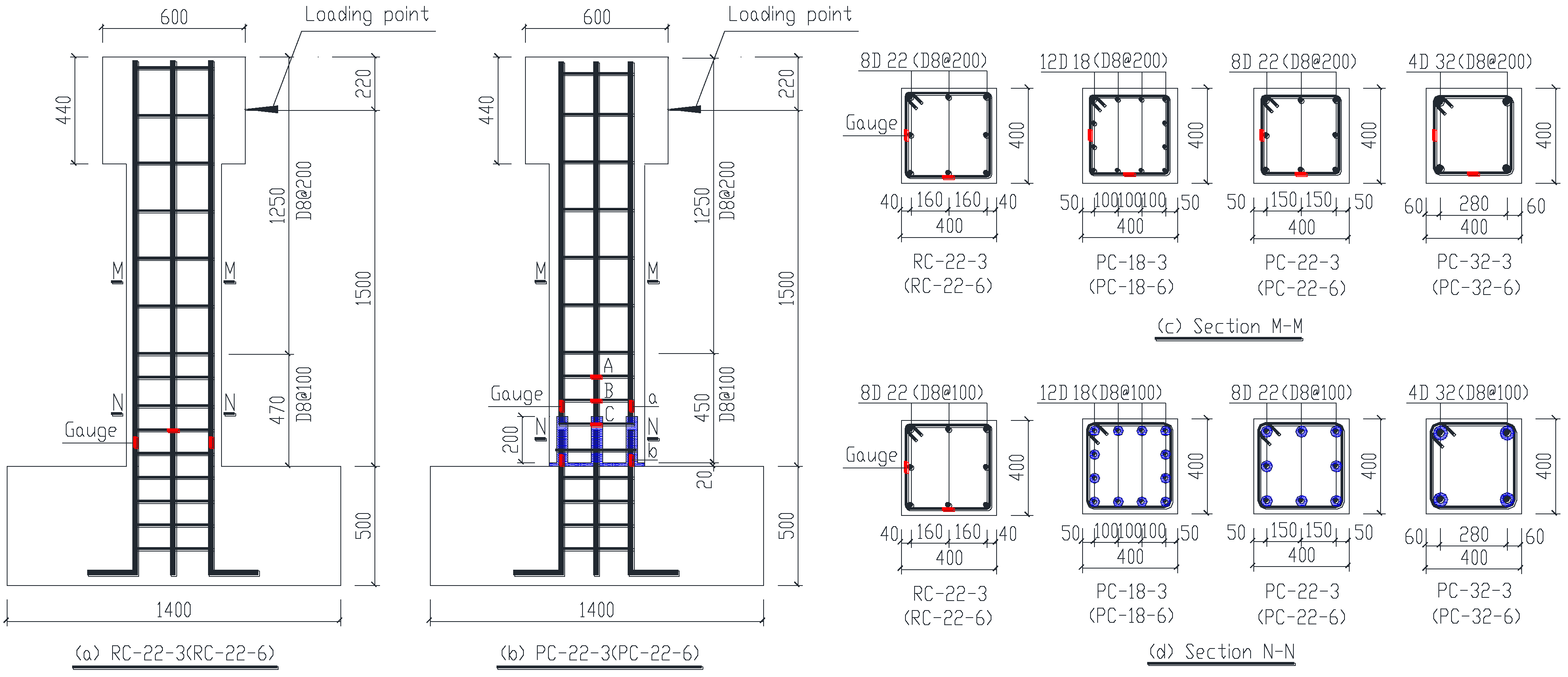
2.1. Tested Specimens and Material Properties

The characteristics of tested specimens are tabulated in Table 1, while their dimensions, reinforcement detailing, and positions of strain gauges are shown in Figure 1. As shown in the figure, the prototype CIP specimens are seismic-designed. A transverse rebar was set at 50 mm above the grouted sleeves [36]. Specimen RC-22-3 means a CIP column with a diameter of longitudinal rebar of 22 mm and axial compressive ratio of 0.3. Similarly, Specimen PC-18-6 represents a PC column with a diameter of longitudinal rebar of 18 mm and axial compressive ratio of 0.6. For remaining specimens, a similar labelling rule is followed. The longitudinal and transverse reinforcements are all HRB400-grade rebars, and the critical values are listed in Table 2. The size of grouted sleeves is presented in Table 3. The grouted sleeves are used for rebar splicing. The pullout test was carried out after the grouting material reached the design strength. It was found that the rebar fractured outside the sleeves without any pullout failure (refer to Figure 2a). The experimental results of rebar (including sleeve) are shown in Table 2. The comparison of constitutive model is shown in Figure 2b. This connection type has little effects on the axial tensile properties of the rebars. The designated strength of commercial concrete is C30. The cylindrical compressive strength, cube compressive strength, and elastic modulus of the concrete are 24.8 MPa, 31.4 MPa, and 33.8 GPa. In accordance with Cementitious Grout for Coupler of Rebar Splicing (JG/T 408-2013) [37] (refer to Figure 3), six specimens with dimensions of 40 mm × 40 mm × 160 mm were cast and cured for 28 days, followed by an axial compressive test (refer to Figure 4). The compressive strength of the grouted material is 90.6 MPa while the initial liquidity and 30 min liquidity of the grouted material are 315 mm and 265 mm, respectively. The grouting operation (refer to Figure 5) was carried out according to the requirements specified in the industry standard Technical Specification for Grout Sleeve Splicing of Rebars (JGJ 355-2015) [38].

2.2. Loading Scheme

A vertical axial force was applied at the top of the column using a hydraulic jack and it was then kept constant during the test. Horizontal low-cycle reversed concentrated load was applied at the column top, which was the assumed inflection point of the prototype column [39] (refer to Figure 6). Displacement control was adopted for horizontal loading, which was divided into two stages. In the initial four increments, a single cycle was adopted at each stage. However, during each of the subsequent displacement increments, at each DR increment the cycle was repeated three times. The loading process was stopped when the horizontal load resistance of the specimen declined to 85% of the load-bearing capacity. Figure 7 shows the loading history curve.

2.3. Measurement Types and Arrangement

The specimen horizontal displacement measurement points were arranged as shown in Figure 6. Several displacement transducers were mounted at the top and bottom column heads in order to monitor the varying of the lateral displacements. The LVDT located at the base of the column had a gauge length of 50 mm, while the LVDT installed on the column head had a gauge length of 200 mm. The strain gauge layout of the transverse reinforcements and longitudinal rebar is shown in Figure 1. For CIP columns, the strain gauges were placed on the two transverse reinforcements located at 20 mm and 60 mm away from the column base, respectively, while the strain gauges in the PC columns were arranged at the two transverse reinforcements immediately above the sleeve. The longitudinal rebar strain gauges were placed at the column base (i.e., the grouted joint) and 20 mm above the sleeve top. Measurements were taken using 10 mm temperature self-compensating resistance strain gauges.

3. Experimental Observations and Failure Modes

The crack propagation status before failure is shown in Figure 8 (face W is the front face), while Figure 9 shows the failure mode of tested specimens after the crushed concrete cover was chiseled away.

3.1. Cast-in-Place Columns

Specimen RC-22-3: When displacement reached a DR of 0.4%, a crack formed at the column side face, which is 100 mm away from the column base. The crack width measured up to 0.2 mm. As the displacement increased to a DR of 0.7%, many horizontal cracks with the maximum width of 0.7 mm appeared on the column side face within 300 mm above the column base. At a DR of 1.0%, a number of diagonal cracks developed on the front face of the column, X-shaped cracks gradually formed, and the longitudinal rebar of the column yielded. At a DR of 1.4%, the concrete cover was loosened, and the plastic deformation of the column was increased. When the DR increased to 1.8%, the column reached its peak load, concrete failure became serious, and clear main diagonal cracks appeared. When the DR increased to 2.2%, the horizontal load-bearing capacity declined to 85% of the peak value and the loading process was stopped. Concrete was crushed and spalled severely. The failure mode is shown in Figure 8a.
For Specimen RC-22-6: Once the DR reached 0.4%, a penetrated crack occurred at the side face of the column base. The longitudinal rebar yielded when the DR reached 0.7%, more cracks formed and extended to the front face of the column, thus forming X-shaped cracks. As the DR increased to 1.2%, the specimen obtained its peak load capacity. The horizontal load-bearing capacity of the member declined to 85% of its peak load when the DR reached 1.7%. As shown in Figure 9a, at this DR, severe concrete crushing and spalling was observed at the column base. The longitudinal rebar was buckled while the transverse rebar was partially opened.

3.2. Prefabricated Concrete Columns

The crack development of PC columns was generally like those of the CIP columns. Generally, in the initial loading phase up to the DR of 0.4%, a horizontal crack firstly occurred at the grouting joint near the column base (Figure 9e), but later it did not change much throughout the complete loading process. Later, cracks also occurred in the column, but due to the positive effects of the grouted sleeves, a local rigid zone was formed in the region of grouting sleeve connection. After member failure, the concrete core in the grouted sleeve region remained essentially intact and the diagonal cracks mainly occurred beyond the sleeve region. The longitudinal rebar beyond the grouted sleeve region yielded due to compression. However, the transverse reinforcements kept their shape, and the plastic hinge zone of the column showed an upward shift. However, when larger diameter rebars were used and the length of the grouted sleeve was increased, the overall stiffness of the column was markedly enhanced. The local failure of the specimens PC-18-3 and PC-32-3 are shown in Figure 9b,d, respectively. As the diameter of longitudinal rebar increases, the bonding stress required between the rebars and concrete increased, and diagonal cracks at the upper part of the sleeve region changed into bonding and anchoring cracks around the longitudinal rebar, which was more obvious for specimens with a high axial compressive ratio (refer to Figure 8c,h).

4. Experimental Result Analysis

4.1. Load-Displacement Hysteretic Loops and Skeleton Curve

The experimental results related to cracking load, yield load, and peak load of each specimen are listed in Table 4. The hysteretic loops of the specimens are shown in Figure 10 while the skeleton curve, which is the envelope connecting the peak points of the first cycle of each DR ratio, is shown in Figure 11. The yield displacement was calculated based on the suggestion from Park [40]. The load that dropped to 85% of the peak load capacity was defined as failure load. The ultimate displacement was defined as the displacement at the failure load.

4.1.1. Influence of Column Fabrication Method

By comparing the hysteretic loops of specimens RC-22-3, PC-22-3, RC-22-6, and PC-22-6, it was found that the hysteretic loops of the CIP columns were plumper. The hysteretic loops of the PC columns were relatively narrower comparing to the corresponding CIP specimens. The main reason is that the rigid region formed by the grouted sleeve makes the plastic hinge region of the column move upward. Thus, after shifting, the plastic hinge zone is beyond the strengthening region with closer transverse reinforcement; thus, the behavior of the plastic hinge in PC columns is worse than that of CIP columns. At the same time, the rigid area also shortens the effective bending length of the specimen. This improves its lateral stiffness. Under a similar ultimate bending moment, PC columns have higher horizontal bearing capacity (Figure 11a). During comparison of the crack patterns of the columns, the failure at the bottom of the CIP columns was more serious than that of the corresponding PC columns.

4.1.2. Influence of the Diameter of Longitudinal Rebar

For the specimen with an axial compressive ratio of 0.3, the hysteretic loops of Specimen PC-18-3 showed obvious pinching, but its displacement at each critical stage (yield strength, peak strength, and ultimate strength) was greater than those of Specimens PC-22-3 and PC-32-3. The hysteretic loops of Specimen PC-22-3 were narrower with greater pinching. The hysteretic loops of Specimen PC-32-3 is the worst, with the lowest deformation capacity, faster decline in load resistance, and poor ductility. For the axial compressive ratio of 0.6, the hysteretic loops of Specimens PC-18-6, PC-22-6, and PC-32-6 showed similar trends to those of the specimens subjected to an axial compressive ratio of 0.3. Comparing the hysteretic loops of the three specimens indicated that large-diameter replacement resulted in more serious pinching and lower energy-dissipation capacity and ductility. With the increase in the diameter of the longitudinal rebar, the bond performance between the reinforcement and the concrete deteriorates faster when the specimen is subjected to low-cycle repeated load. Thus, the ductility and energy consumption capacity are reduced when increasing the diameter of longitudinal rebar but keeping similar reinforcement ratio.

4.1.3. Effects of the Axial Compressive Ratio

A comparison of the hysteretic loops of Specimens PC-18-3 and PC-18-6 revealed that the ultimate DR of the specimens with a high axial compressive ratio were lower than those of the specimens with a low axial compressive ratio. Moreover, the decreasing of energy-dissipation capacity was as significant as increasing the axial compressive ratio. The shape of hysteretic loop of Specimens PC-22-3 and PC-22-6 was not significantly different from those of Specimens PC-32-3 and PC-32-6; the ultimate DR of specimens with a high axial compressive ratio was reduced in comparison to those of specimens with a low axial compressive ratio. This could be attributed to the specimens with a high axial compressive ratio achieving lower pinching. Moreover, the specimens with a high axial compressive ratio had greater peak loads.

4.2. Stiffness Degeneration

The secant stiffness, K, at stage i was calculated as Ki = Pii, where Pi and Δi were the peak load and corresponding displacement at loading stage i, respectively. The stiffness degradation curves of the specimens are shown in Figure 12.

4.2.1. Influence of Column Fabrication Method

A local rigid zone formed in the grouted sleeve region of the PC columns; thus, the effective length decreased and the shear span/depth ratio decreased, while the overall lateral stiffness was enhanced compared to those of the CIP columns. As shown in Figure 12a, the stiffness degeneration of the PC columns was similar to that of CIP columns under an axial compressive ratio of 0.3. When the axial compressive ratio was 0.6, the initial stiffness of the PC columns was larger, and their stiffness degeneration was slower.

4.2.2. Influences of Large-Diameter Rebar Replacement and Axial Compressive Ratio

As shown in Figure 12b, for specimens with identical diameter of longitudinal rebar, the lateral stiffness of the column increased with the increase in the axial compressive ratio, but the corresponding stiffness degeneration was faster. The initial stiffness of Specimen PC-22-6 was highest, experiencing the fastest declining. The initial stiffness of the columns with a low compression ratio was enhanced with the increase of the diameter of the longitudinal rebar, but it followed a similar trend in stiffness declining. For the specimens with a longitudinal rebar diameter of 22 mm, the initial stiffness of the specimens with an axial compressive ratio of 0.6 was clearly greater than that of the specimens with an axial compressive ratio of 0.3.

4.3. Displacement Ductility

The results of the specimen ductility ratio µΔ and ultimate drift ratio θm are shown in Figure 13 and Figure 14, respectively. From the figure, the ductility ratio of the PC columns ranged from 1.8 to 2.5, with the mean value of 2.2. The ultimate drift ratio was between 1/37 and 1/75, with the mean value of 1/52, i.e., less than the limiting DR value of 1/50 for RC frames subjected to a major earthquake [22]. By comparing CIP Specimens RC-22-3 and RC-22-6 with corresponding PC Specimens PC-22-3 and PC-22-6, it was discovered that the ductility of the PC columns was similar to that of the CIP columns under an axial compressive ratio of 0.3. However, under an axial compressive ratio of 0.6, the ductility of the PC columns was lower than that of CIP ones. At 0.3 axial compressive ratio, when the rebar diameter increased from 18 mm to 22 mm and 32 mm, the ductility ratio decreased by 8% and 24%, respectively. Additionally, the ultimate drift ratio decreased by 22% and 26%, respectively. Similarly, at 0.6 axial compressive ratio, when the rebar diameter increased from 18 mm to 22 mm and 32 mm, the ductility ratio decreased by 14% and 18%, respectively. Additionally, the ultimate drift ratio decreased by 13% and 19%, respectively.

4.4. Energy-Dissipation Capacity

The area enclosed by the hysteretic loop was used to calculate the accumulative energy dissipation of a member (Figure 15). It was observed that the energy-dissipation capacity of the PC columns was inferior to that of the CIP ones. At an axial compressive ratio of 0.3, when the rebar diameter increased from 18 mm to 22 mm and 32 mm, the energy-dissipation capacity decreased by 26% and 29%, respectively. At an axial compressive ratio of 0.6, the energy-dissipation capacity decreased by 3.6% and 9.6%, respectively, when the rebar diameter increased from 18 mm to 22 mm and 32 mm. The PC column with the longitudinal rebar diameter of 22 mm had a comparable energy-dissipation capacity as the PC column with a reinforcement diameter of 32 mm.

4.5. Hysteretic Loops of Reinforcement Strain

Under the action of low-cycle reverse horizontal loading, the longitudinal rebar of the specimens gradually yielded, the reinforcement cover cracked and spalled. While the concrete core expanded laterally under vertical compression, the transverse reinforcements constrained circumferentially the concrete core, thus enhancing the load-bearing capacity and ductility of the specimens. Reinforcement strain gauges were attached at the locations shown in Figure 1. The strain gauges were installed only at the base of the CIP columns and at the grouted sleeve region for PC columns (Figure 1).

4.5.1. Longitudinal Rebar

The longitudinal rebar strains recorded in the PC columns are shown in Figure 16. It was observed that the longitudinal rebar strain was strongly affected by the axial compressive ratio. For the specimens with an axial compressive ratio of 0.3, the longitudinal rebar yielded in both tension and compression. After yielding, the strain value kept increasing, and the hysteretic loops were relatively plump. In the columns with an axial compressive ratio of 0.6, the longitudinal rebar generally only experienced compression yield, but no tensile yield, and the hysteretic loops were relatively narrower. The strains in longitudinal rebar at the top and base of the grouted sleeve were essentially similar, and the grouted sleeve connection did not change the stress transfer of the longitudinal rebar. Moreover, the large-diameter rebar replacement had little influence on its strain development.

4.5.2. Transverse Reinforcements

The transverse reinforcement strains in the PC columns are shown in Figure 17. For PC specimens subjected to an axial compressive ratio of 0.3, the transverse strain increased slowly with increasing the horizontal DR. Even at the final test, the transverse strain did not yield. However, for PC specimens with an axial compressive ratio of 0.6, the transverse strain increased much faster when the horizontal DR increased. It can be seen that for PC-18-6 and PC-22-6, the transverse strain yielded. Moreover, from tested specimens, it was found that the transverse strain in section C was significantly less than that of section B as grouted sleeves formed a rigid zone and plastic hinges formed just beyond the grouted sleeve region.

5. Conclusions and Suggestions

Cyclic monotonic loading in order to evaluate seismic behavior was carried out on eight full-size columns with identical concrete strength, longitudinal rebar ratio, and transverse reinforcement ratio, but subjected to axial compressive ratios of 0.3 and 0.6. Six were prefabricated and the remaining two were cast in place for reference. The following conclusions can be drawn from the test results and analysis:
(1)
Under low-cycle reverse loading, increasing the diameter of longitudinal rebar, the bonding stress required between the rebars and concrete increased, which resulted in the crack pattern changing from diagonal cracks just beyond the grouted sleeve region to bond failure around the longitudinal rebar bars. Furthermore, the bond-slip of the rebars became evident, especially in the PC columns with a longitudinal rebar diameter of 32 mm under an axial compressive ratio of 0.3. It made the energy-dissipation capacity and ductility of PC columns decrease with the increase in the diameter of longitudinal rebar.
(2)
The longitudinal bar diameter had little effect on the cracking load, and the cracking load of the specimens with an axial compressive ratio of 0.6 was greater than that of the specimens with an axial compressive ratio of 0.3. The cracking load of PC columns was greater than that of CIP columns. When the diameter of the longitudinal rebar increased from 18 mm to 22 mm, the yield load and ultimate load of PC columns increased. Conversely, when the diameter of the longitudinal rebar increased from 22 mm to 32 mm, the yield load and ultimate load of PC columns decreased. Thus, it is necessary to conduct more tests to deeply understand the effects of diameter of longitudinal rebar in the future.
(3)
For PC columns, a local rigid zone formed in the grouted sleeve region; thus, the effective length decreased under the horizontal load, the shear span ratio increased, and the overall lateral stiffness was enhanced compared to those of the CIP columns. Moreover, the load resistance was always greater, but ductility was poorer than those of the CIP columns.
(4)
PC columns reinforced with 32 mm diameter rebar had poorer seismic performance than the columns reinforced with 22 mm or 18 mm diameter rebar but with 100% and 200% increased assembly efficiency, respectively. When a precast column with 32 mm longitudinal reinforcement is used, to further eliminate the negative effects of large rebar replacement, it is recommended to design a much higher transverse reinforcement ratio at the grouted sleeve region. If possible, the strengthening region with closer transverse reinforcement spacing due to potential plastic hinge development should be extended to two times the depth of the column due to the fact that the position of the plastic hinge may be shifted upward beyond the grouted sleeve region.
(5)
In general, the reduction in seismic performance of precast columns caused by the replacement of large-diameter rebar is limited. In addition, it still has a large space for lifting. Compared with the potential improvement of assembly efficiency and construction quality, a precast column with large-diameter rebar is worthy of promotion.

Author Contributions

Conceptualization, Q.W.; methodology, Q.W.; formal analysis, Q.W.; investigation, Q.W. and W.Q.; resources, Q.W.; data curation, Q.W; writing—original draft preparation, Q.W. and W.Q.; writing—review and editing, Q.W., and C.L.; visualization, Q.W.; supervision, C.L.; project administration, Q.W. and C.L.; funding acquisition, Q.W. and C.L.; All authors have read and agreed to the published version of the manuscript.

Funding

This research was funded by the Guangxi Natural Science Foundation, grant number Nos. 2021GXNSFFA196001 and 2019GXNSFAA245055; National Natural Science Foundation of China, grant number Nos. U22A20244 and 52168028; Key R&D projects in the Guangxi Autonomous Region, grant number No. AA20302006; Guanxi Key Laboratory of New Energy and Building Energy Saving, grant number No. 22-J-21-10.

Data Availability Statement

The data presented in this study are available on request from the authors.

Conflicts of Interest

The authors declare no conflict of interest.

References

  1. ACI 550.1R-09; Guide to Emulating Cast-in-Place Detailing Seismic Design of Precast Concrete Structures. American Concrete Institute: Detroit, MI, USA, 2009.
  2. ACI T1.2-03; Special Hybrid Moment Frames Composed of Discretely Jointed Precast and Post-Tensioned Concrete Members. American Concrete Institute: Detroit, MI, USA, 2003.
  3. PCI (Precast/Prestressed Concrete Institute). PCI Design Handbook: Precast and Prestressed Concrete, 7th ed.; Precast/Prestressed Concrete Institute: Chicago, IL, USA, 2010. [Google Scholar]
  4. FIB (The International Federation for Structural Concrete). Fib Model Code for Concrete Structures 2010; The International Federation for Structural Concrete: Lausanne, CH, USA, 2012. [Google Scholar]
  5. Kato, H.; Ichizawa, Y.; Takamatsu, K. Earthquake response of an eleven-story precast prestressed concrete building by substructure pseudo dynamic test. In Proceedings of the 12th World Conference on Earthquake Engineering, Auckland, New Zealand, 30 January–4 February 2000. [Google Scholar]
  6. JGJ 1-2014; Technical Specification for Precast Concrete Structures. China Architecture & Building Press: Beijing, China, 2014.
  7. JGJ 224-2010; Technical Specification for Framed Structures Comprised of Precast Prestressed Concrete Components. China Architecture & Building Press: Beijing, China, 2010.
  8. Park, R. A perspective on the seismic design of precast concrete structures in New Zealand. PCI. J. 1995, 40, 40–60. [Google Scholar] [CrossRef]
  9. Rave-Arango, J.F.; Blandón, C.A.; Restrepo, J.I.; Carmona, F. Seismic performance of precast concrete column-to-column lap-splice connections. Eng. Struct. 2018, 172, 687–699. [Google Scholar] [CrossRef]
  10. Yamashita, R.; Sanders, D.H. Seismic performance of precast unbonded prestressed concrete columns. ACI. Struct. J. 2009, 106, 821–830. [Google Scholar] [CrossRef]
  11. Kim, C.S.; Lim, W.Y.; Park, H.G.; Oh, J.K. Cyclic loading test for cast-in-place concrete-filled hollow precast concrete columns. ACI. Struct. J. 2016, 113, 205–215. [Google Scholar] [CrossRef]
  12. Bull, D.K. Guidelines for the Use of Structural Precast Concrete in Buildings. Centre for Advanced Engineering, University of Canterbury: Chirstchurch, New Zealand, 2000. [Google Scholar]
  13. Ong, H.Y. Experimental Study of Grout Filled Splice Sleeve Integrated with Shear Key for Precast Concrete Connection; Technological University of Malaysia: Johor, Malaysia, 2010. [Google Scholar]
  14. Ameli, M.J.; Parks, J.E.; Brown, D.N.; Pantelides, C.P. Seismic evaluation of grouted splice sleeve connections for reinforced precast concrete column-to-cap beam joints in accelerated bridge construction. PCI. J. 2015, 60, 80–103. [Google Scholar] [CrossRef]
  15. Ogura, K. Testing Program for the NMB Splice Sleeve; Splice Sleeve North America Inc.: Livonia, MI, USA, 2005. [Google Scholar]
  16. Tazarv, M. Saiidi MS. Seismic design of bridge columns incorporating mechanical bar splices in plastic hinge regions. Eng. Struct. 2016, 124, 507–520. [Google Scholar] [CrossRef]
  17. Ou, Y.C.; Alrasyid, H.; Haber, Z.B.; Lee, H.J. Cyclic behavior of precast high-strength reinforced concrete columns. ACI. Struct. J. 2015, 112, 839–850. [Google Scholar] [CrossRef]
  18. Kim, Y.M. A Study of Pipe Splice Sleeves for Use in Precast Beam-Column Connections; University of Texas at Austin: Austin, TX, USA, 2000. [Google Scholar]
  19. Riva, P. Seismic behaviour of precast column-to-foundation grouted sleeve connections. In Advances in Engineering Structures, Mechanics & Construction; Springer: Dordrecht, The Netherlands, 2006; pp. 121–128. [Google Scholar] [CrossRef]
  20. Zhao, Y.; Li, R.; Wang, X.F.; Han, C. Experimental research on seismic behaviors of precast concrete columns with large-diameter and high-yield strength reinforcements splicing by grout-filled coupling sleeves. China Civil. Eng. J. 2017, 50, 31–39+75. (In Chinese) [Google Scholar] [CrossRef]
  21. Kuttab, A.; Dougill, J.W. Grouted and dowelled jointed precast concrete columns: Behaviour in combined bending and compression. Mag. Concr. Res. 1988, 40, 131–142. [Google Scholar] [CrossRef]
  22. GB 50011-2010; Code for Seismic Design of Buildings. China Architecture & Building Press: Beijing, China, 2010.
  23. Tullini, N.; Minghini, F. Grouted sleeve connections used in precast reinforced concrete construction-experimental investigation of a column-to-column joint. Eng. Struct. 2016, 127, 784–803. [Google Scholar] [CrossRef]
  24. Tullini, N.; Minghini, F. Cyclic test on a precast reinforced concrete column-to-foundation grouted duct connection. Bull. Earthq. Eng. 2020, 18, 1657–1691. [Google Scholar] [CrossRef]
  25. Ameli, M.J.; Brown, D.N.; Parks, J.E.; Pantelides, C.P. Seismic column-to-footing connections using grouted splice sleeves. ACI. Struct. J. 2016, 113, 1021–1030. [Google Scholar] [CrossRef]
  26. Al-Jelawy, H.M.; Mackie, K.R.; Haber, Z.B. Shifted plastic hinging for grouted sleeve column connections. ACI. Struct. J. 2018, 115, 1101–1114. [Google Scholar] [CrossRef]
  27. Liu, H.; Wang, Z.; Xu, C.; Du, X. Influence of axial compressive ratio on the seismic performance of precast columns with grouted sleeve connections. J. Struct. Eng. 2021, 147, 04021194. [Google Scholar] [CrossRef]
  28. Guan, D.; Xu, R.; Yang, S.; Chen, Z.; Guo, Z. Development and seismic behavior of a novel UHPC-shell strengthened prefabricated concrete column. J. Build. Eng. 2022, 46, 103672. [Google Scholar] [CrossRef]
  29. Cao, X.Y.; Shen, D.; Feng, D.C.; Wang, C.L.; Qu, Z.; Wu, G. Seismic retrofitting of existing frame buildings through externally attached sub-structures: State of the art review and future perspectives. J. Build Eng. 2022, 57, 104904. [Google Scholar] [CrossRef]
  30. Cao, X.Y.; Feng, D.C.; Wang, Z.; Wu, G. Parametric investigation of the assembled bolt-connected buckling-restrained brace and performance evaluation of its application into structural retrofit. J. Build Eng. 2022, 48, 103988. [Google Scholar] [CrossRef]
  31. Cao, X.Y.; Feng, D.C.; Wu, G.; Wang, Z. Experimental and theoretical investigations of the existing reinforced concrete frames retrofitted with the novel external SC-PBSPC BRBF sub-structures. Eng. Struct. 2022, 256, 113982. [Google Scholar] [CrossRef]
  32. Alavi-Dehkordi, S.; Mostofinejad, D.; Alaee, P. Effects of high-strength reinforcing bars and concrete on seismic behavior of RC Beam-column joints. Eng. Struct. 2019, 183, 702–719. [Google Scholar] [CrossRef]
  33. Sun, Z.; Feng, D.C.; Sun, Y.; Yuan, J. Bond-slip behavior of bundled steel/FRP bars and its implementation in high-fidelity FE modeling of reinforced concrete beams. Constr. Build. Mater. 2021, 286, 122887. [Google Scholar] [CrossRef]
  34. Sun, Z.; Fu, L.; Feng, D.C. Experimental study on the flexural behavior of concrete beams reinforced with bundled hybrid steel/FRP bars. Eng. Struct. 2019, 197, 109443. [Google Scholar] [CrossRef]
  35. Pang, J.B.; Eberhard, M.O.; Stanton, J.F. Large-bar connection for precast bridge bents in seismic regions. J. Bridge. Eng. 2010, 15, 231–239. [Google Scholar] [CrossRef]
  36. GB/T 51231-2016; Technical Standard for Assembled Buildings with Concrete Structure. China Architecture & Building Press: Beijing, China, 2016.
  37. JG/T 408-2013; Cementitious Grout for Coupler of Rebar Splicing. China Standards Press: Beijing, China, 2013.
  38. JGJ 355-2015; Technical Specification for Grout Sleeve Splicing of Rebars. China Architecture & Building Press: Beijing, China, 2015.
  39. JGJ/T 101-2015; Specification for Seismic Test of Buildings. China Construction Industry Press: Beijing, China, 2015.
  40. Park, R. Evaluation of ductility of structures and structural assemblages from laboratory testing. Bull. N. Z. Soc. Earthq. 1989, 22, 155–166. [Google Scholar] [CrossRef]
Figure 1. Specimen size, reinforcement, location of strain gauges for steel.
Buildings 13 00706 g001
Figure 2. Pullout test of sleeve connecting rebar and constitutive relation: (a) pullout test; (b) constitutive relation.
Buildings 13 00706 g002
Figure 3. Fluidity test of grouting material.
Buildings 13 00706 g003
Figure 4. The compression test of the grouting material.
Buildings 13 00706 g004
Figure 5. Fabrication of specimens: (a) bottom of column; (b) clean base; (c) column hoisting; (d) joint grouting.
Buildings 13 00706 g005
Figure 6. Test setup. (a) Sketch of test setup. (b) Photo of the test setup.
Buildings 13 00706 g006
Figure 7. Applied lateral displacement history.
Buildings 13 00706 g007
Figure 8. Failure patterns of specimens: (a) RC-22-3; (b) RC-22-6; (c) PC-18-3; (d) PC-22-3; (e) PC-32-3; (f) PC-18-6; (g) PC-22-6; and (h) PC-32-6.
Buildings 13 00706 g008
Figure 9. Local failure features of specimens: (a) RC-22-3; (b) PC-18-3; (c) PC-22-6; (d) PC-32-3; and (e) PC-32-6.
Buildings 13 00706 g009
Figure 10. Load-displacement hysteretic loops: (a) RC-22-3; (b) RC-22-6; (c) PC-18-3; (d) PC-22-3; (e) PC-32-3; (f) PC-18-6; (g) PC-22-6; and (h) PC-32-6.
Buildings 13 00706 g010aBuildings 13 00706 g010b
Figure 11. Comparison of the envelope of the hysteresis curves: (a) effects of fabrication methods; (b) effects of loading direction and rebar diameter.
Buildings 13 00706 g011
Figure 12. Comparison of the stiffness degradation of tested specimens: (a) effects of fabrication methods; (b) effects of loading direction and rebar diameter.
Buildings 13 00706 g012
Figure 13. Ductility coefficient.
Buildings 13 00706 g013
Figure 14. Ultimate DR.
Buildings 13 00706 g014
Figure 15. Energy-dissipation capacity.
Buildings 13 00706 g015
Figure 16. Reinforcement strain of assembly column: (a) RC-22-3; (b) RC-22-6; (c) PC-18-3; (d) PC-22-3; (e) PC-32-3; (f) PC-18-6; (g) PC-22-6; (h) PC-32-6.
Buildings 13 00706 g016aBuildings 13 00706 g016b
Figure 17. Transverse rebar strain of assembly column: (a) RC-22-3; (b) RC-22-6; (c) PC-18-3; (d) PC-22-3; (e) PC-32-3; (f) PC-18-6; (g) PC-22-6; (h) PC-32-6.
Buildings 13 00706 g017aBuildings 13 00706 g017b
Table 1. Main parameters of specimens.
Specimen IDAxial Compressive Ratio nReinforcementReinforcement Ratio ρ (%)Transverse RebarTransverse Rebar Ratio ρv (%)Production Method
RC-22-30.38D222D10@100/2000.98/0.49Cast-in-place
RC-22-60.68D222D10@100/2000.98/0.49Cast-in-place
PC-18-30.312D182D10@100/2000.98/0.49Prefabricated
PC-22-30.38D222D10@100/2000.98/0.49Prefabricated
PC-32-30.34D322D10@100/2000.98/0.49Prefabricated
PC-18-60.612D182D10@100/2000.98/0.49Prefabricated
PC-22-60.68D222D10@100/2000.98/0.49Prefabricated
PC-32-60.64D322D10@100/2000.98/0.49Prefabricated
Note: n = N/(fc × A), A represents section area of column, fc represents measured value of concrete axial compressive strength.
Table 2. Mechanical properties of reinforcements.
Diameter of ReinforcementYield Strength fy (MPa)Ultimate Strength fst (MPa)Young’s Modulus Es (GPa)Elongation δ (%)
D10401.3600.820023
D18404.5 (417)605.5 (609)20022
D22411.3 (429)600.3 (602)20022
D32400.7 (423)603.9 (601)20020
Note: the values in brackets are the strength of the reinforcement after connection with grouting sleeve.
Table 3. Specifications of semi-grouting sleeve.
Sleeve ModelApplicable Reinforcement Diameter (mm)Outer Diameter (mm)Internal Diameter (mm)Length (mm)
GTB4-18-A184234160
GTB4-22-A224838195
GTB4-32-A326048360
Table 4. Test results summary.
Specimen NumberCrack PointYield PointPeak PointUltimate PointµΔθmE (kN·m)
Pcr (kN)Δcr (mm)Py (kN)Δy (mm)Pp (kN)Δp (mm)Pu (kN)Δu (mm)
RC-22-311632071324426208322.51/4710.6
RC-22-613032261126418220252.31/609.4
PC-18-312032001623234196402.51/3711.2
PC-22-312232201528225245322.31/478.3
PC-32-312532181524424211301.91/508.0
PC-18-614532151125419214242.21/638.3
PC-22-615532651131917267211.91/718.0
PC-32-615732341127318230201.81/757.5
Note: Pcr = cracking load; Δcr = cracking horizontal displacement; Py = yield lateral load; Δy = yield horizontal displacement; Pp = peak lateral load; Δp = peak horizontal displacement; Pu = ultimate lateral load; Δu = ultimate horizontal displacement. μΔ = ductility ratio (μΔ = Δuy), θm = ultimate drift ratio (θm = Δu/l, l is column height), E = cumulative energy dissipation.
Disclaimer/Publisher’s Note: The statements, opinions and data contained in all publications are solely those of the individual author(s) and contributor(s) and not of MDPI and/or the editor(s). MDPI and/or the editor(s) disclaim responsibility for any injury to people or property resulting from any ideas, methods, instructions or products referred to in the content.

