Article

Investigating the Influence of Thermal Conductivity and Thermal Storage of Lightweight Concrete Panels on the Energy and Thermal Comfort in Residential Buildings

Department of Civil and Construction Engineering, Swinburne University of Technology, Hawthorn, VIC 3122, Australia
*
Author to whom correspondence should be addressed.
Buildings 2023, 13(3), 720; https://doi.org/10.3390/buildings13030720
Submission received: 7 February 2023 / Revised: 27 February 2023 / Accepted: 6 March 2023 / Published: 9 March 2023
(This article belongs to the Section Building Materials, and Repair & Renovation)

Abstract

:
Phase change materials (PCM) are integrated into lightweight concrete (LWC) panels to increase their thermal mass. However, the integration of PCM into LWC also increases the thermal conductivity of the panels, which may have a negative impact. This study investigated the impact of thermal resistance and storage of LWC panels on thermal comfort and energy use in buildings. Six different LWC panels with varying levels of thermal conductivity and storage were developed using various combinations lightweight aggregates and PCM. The experimentally measured properties were used in building simulation software EnergyPlus V9.3 to calculate overheating and building energy consumption for each panel. The result showed that thermal mass influences severe discomfort hours more than thermal resistance. However, the level of influence depends on the position of the panels compared to the insulation layer. The presence of an insulation layer reduced the energy savings rate. The cooling energy consumption was more influenced by the thermal mass, whereas the heating was more influenced by the resistance of the wall. Overall, the LWC panel with the highest thermal mass was the best to reduce severe discomfort hours and energy consumption despite having the highest thermal conductivity. The outcome of this study can help to design an external building envelope with PCM panel as per user requirements, which could be to reduce overheating or cooling only, heating only, or both cooling and heating.

1. Introduction

Buildings are responsible for 32% of total energy use worldwide, including residential and commercial energy consumption of 24% and 8%, respectively. Energy use in buildings is increasing due to population growth, changes in human lifestyle, and technological advancement. Energy consumption in buildings contributes to 30% of total greenhouse gas (GHG) emissions in the world, while construction materials account for 13% of total CO2 emissions in buildings [1]. They are responsible for global warming. Already, the average air temperature in Europe has increased by 1.7 °C compared to the preindustrial period [2], and the average Earth temperature is expected to increase by 1.5–6 °C over the next century. This global warming has already increased the frequency of heatwave periods [3] across the globe.
Heatwaves exacerbate summertime overheating by increasing indoor air temperature in buildings [4]. Occupants spend 90% of their time indoors. Residents have shown concern regarding summertime overheating in a multi-story building in Melbourne. Sharifi et al. [5] found from their investigation that the indoor air temperature was higher than adaptive thermal comfort criteria by 343 h on the top floor of a house built after 2010 in the summer climate of Adelaide. An internally insulated UK dwelling was found to be overheated during the 2015 summer when the daily maximum outdoor air temperature was between 25 and 30 °C [6]. Similarly, UK and Canadian dwellings were overheated when the summertime temperature was above 30 °C without cross-ventilation at night [4,7].
Building overheating has a severe health hazard. It caused 1700 heat-related mortalities in France and Portugal in 2022 and 167 deaths in Victoria, Australia [4]. In European countries, heating, ventilation, and air conditioning (HVAC) are responsible for 20% of building energy consumption and will increase by 72% by 2030 due to climate change [2]. The cooling energy use is expected to increase by 223–1050% and 26–101% in Switzerland [8] and Australia [9], respectively, by 2050. However, introducing energy conservation measures, including materials (low carbon concrete [8,10], insulation [9], phase change, and retroreflective [11]), energy efficient and intelligent monitoring of air conditioning systems [12], and using renewable energy resources, should reduce building energy use and GHG emission [13]. For instance, phase change materials (PCMs) have the potential to reduce cooling energy demand by 20–50% and mitigate overheating by 4.7 °C in air-conditioned and passive buildings in temperate and hot climates, respectively [14].
PCMs are latent heat energy storage materials. They store and release thermal energy with the heat of fusion and solidification by changing phases. They can reduce and shift peak cooling demand in buildings, resulting in lower cooling costs. PCMs are applied in building with different encapsulation techniques, including active and passive measures [15]. They can be applied in building envelopes as a structural component (tube, pouch, and panel) and construction materials (direct mixing and form-shape stabilization) [16]. Form-shape stabilization is better than direct mixing and macro-encapsulation due to its high structural integrity and lack of leakage and acidification [17]. The form-shape stabilization techniques have been studied due to their simple and energy efficient preparation procedure, low cost, better structural integrity, thermal and chemical stability, and mechanical reliability [17]. The form-stable PCM (FSPCM) composite was used to develop thermal energy storage panels (TESP). They were used in buildings to reduce and shift peak cooling demand, reduce energy consumption, and mitigate thermal discomfort [18].
Several studies investigated the effect of melting point temperature [19,20], thermal conductivity [21,22], thickness [23], location [24], configuration [25], orientation [26], and structural [27] and surface materials [22] on the thermal performance of PCMs experimentally, numerically, and through analytical modeling. The optimum melting point temperature (OMPT) was determined as 24–28 °C [19], 18–22 °C [19], and 34 °C [28] in cold, warm, and hot climates, respectively. The OMPT of a passive building (20–26 °C) was higher than air-conditioned buildings (22–24 °C), depending on climatic conditions [20]. For instance, Kumar et al. [25] found that OMPT for wintertime (24 °C) was lower than in the summer period (30 °C) in a typical Victorian house. Internal loading conditions also increase PCM’s OMPT for the internal wall [29]. Khalifa and Abbas found that PCM reduced and shifted peak cooling load in low thermal mass envelopes more than in heavy thermal mass envelopes [23]. PCM application reduced cooling load by 43–87% [30] and 4–7% [31] in low and high thermal mass reference envelopes, respectively. Ahangari and Maerefat developed novel dynamic PCM panels for buildings. The PCM panel switches its location in the daytime and nighttime to absorb internal heat and release it to the surroundings. The dynamic PCM application reduced the cooling load by 136% compared to 21% of static PCM panel applications in the Mediterranean climate of Lleida [24].
Ramakrishnan et al. [18] integrated PCM in concrete panels. Their experimental study showed that the PCM-integrated concrete panel reduced test heat indoor air temperature by 2.4 °C more than the normal concrete panel (NCP) in the cool temperate climate of Melbourne. Their results also showed that the PCM-integrated concrete panel has a thermal conductivity of two-thirds that of NCP. Nowadays, ultralightweight, lightweight, and thermal insulating construction materials are becoming popular in building construction because of their lightweight and high structural strength properties. Previous researchers developed lightweight and thermal insulating concrete materials using expanded glass and aerogel [32]. For instance, Adhikary et al. [33] developed lightweight concrete (LWC) using silica aerogel, expanded glass, and prefabricated plastic and investigated their chemical stability and thermal and structural properties. The developed LWC were chemically stable, but replacing cement with lightweight fillers maximally reduced compressive strength and density by 60% and 12%, respectively, to achieve minimum thermal conductivity of 0.302 W/m-K. Reducing thermal conductivity and density reduces the thermal mass of LWC. Thus, buildings constructed with lightweight concrete (LWC) panels are prone to overheating and are energy inefficient. Therefore, form-stable PCM (FSPCM) composites were integrated into lightweight construction material by previous researchers to increase their thermal storage using expanded perlite [34], silica aerogel [35], lightweight aggregates [36], expanded clay [37], and hollow ceramsite [38]. The FSPCM-integrated lightweight wallboard reduced indoor air temperature by 0.9–1.5 °C and 1.2–5.8 °C in cool and hot climates, respectively [34].
However, the FSPCM-integrated lightweight concrete has higher thermal conductivity than lightweight concrete panels [39], which may negatively impact the indoor air temperature, comfort, and energy savings. The thermal conductivity of FSPCM composites is higher than the lightweight aggregates such as aerogel and expanded perlite because of the higher thermal conductivity of PCM. Therefore, the addition of PCM in lightweight insulated concrete may increase thermal conductivity, although it increases thermal storage as well. There is a need to understand the impact of thermal resistance and effective thermal storage of thermally enhanced lightweight concrete panels on thermal comfort and energy savings in residential buildings. The research question that should be answered is: What is the relationship between the thermal resistance and thermal storage of external walls with indoor thermal discomfort and energy consumption?
Therefore, this study aimed to investigate the impact of thermal resistance and storage on thermal discomfort and energy savings in a residential building with various lightweight panels integrated into external walls. This study has the following objectives:
  • To develop and measure the thermal properties of various lightweight panels with varying resistance and storage. Most of the previous research used hypothetical envelope properties to numerically investigate the impact of material properties on building thermal and energy performance. Kumar et al. [25] retrofit a typical Victorian house using phase material blanket, insulation, and aerogel rendered layer-wise. Their applications on the outside of an external wall were the most economical retrofit option with optimum phase change temperature and thickness of 25–32 °C and 25 mm, respectively. Al-Yasiri and Szabo determined that applying a 15 mm thick paraffin wax layer on the top of the test unit in a hot climate had lowered daily operative temperature by 6 °C. They also reduced the daily CO2 emissions by 2 kg in an air-conditioned house [40]. Yang et al. [41] compared the melting behavior of macro-encapsulation of PCM panels with pyramidal and tetrahedral surfaces. They found that the pyramidal surface melted 21% more PCM than tetrahedral surface due to higher surface area exposed to indoor environment. PCM and concrete panels were considered separate layers in the simulation instead of a single layer of PCM-integrated concrete panel, which is not real. To overcome this issue, six different lightweight concrete panels were developed, and their thermal properties were measured using appropriate standards. For instance, ASTM C830, ASTM C109, and ASTM D5334 standards were followed to measure density, compressive strength, and thermal conductivity, respectively, of developed concrete material [15,17].
  • To numerically investigate the impact of thermal resistance and storage of developed lightweight concrete panels on thermal comfort and energy savings in a case study house. The measured thermal properties in objective 1 were used in the respective numerical modeling of the lightweight panels.
In this study, Section 2 describes the research methodology, including sample preparation, measurement of thermal properties, and numerical modeling procedure to calculate thermal discomfort and energy consumption. Section 3 presents the results and discussion. Finally, Section 4 concludes the key findings of the present study.

2. Research Methodology

2.1. Sample Preparation

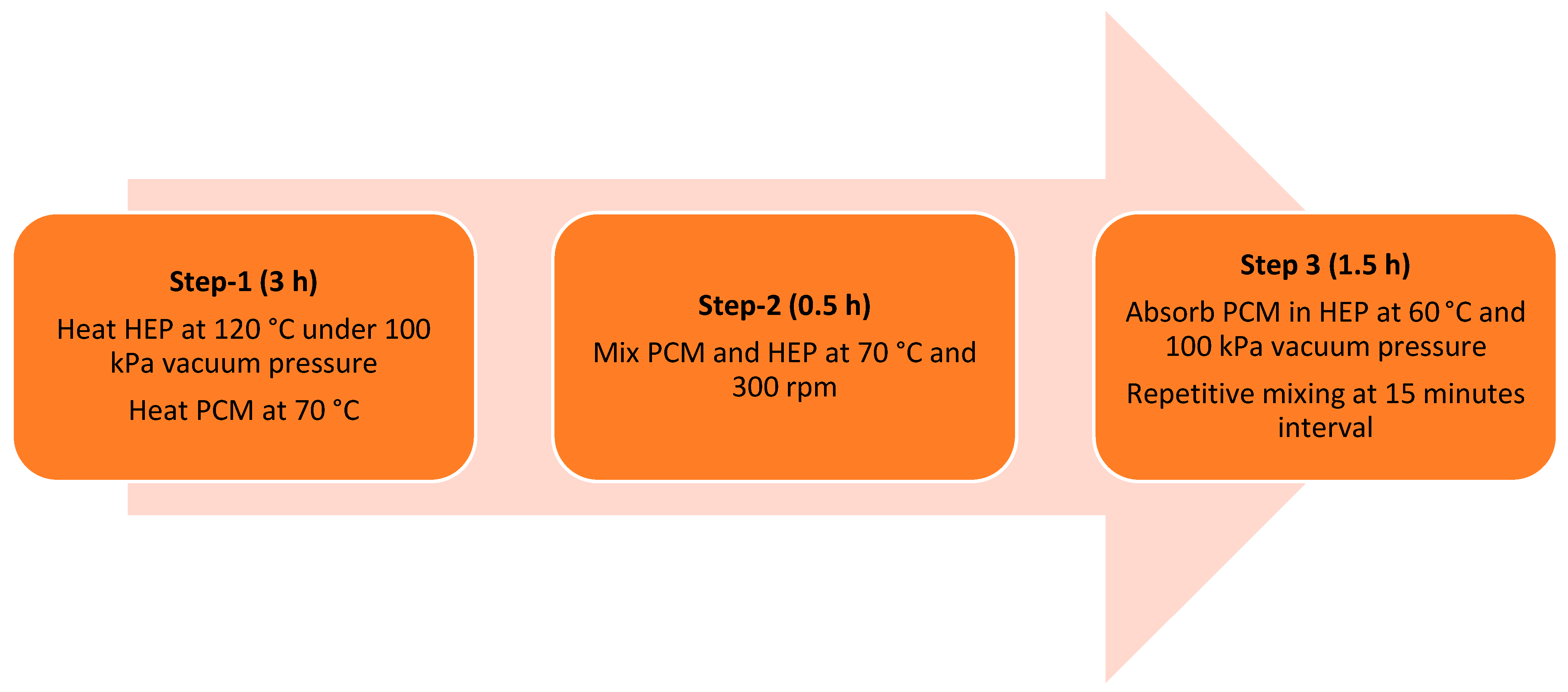
2.1.1. Preparation of Form-Stable PCM (FSPCM) Composites

In this study, hydrophobic expanded perlite (HEP) porous material was used to encapsulate capric acid (CA) PCM following the steps shown in Figure 1, as recommended in a previous study of the present authors [15] to prepare form-stable PCM (FSPCM) composites. The phase change temperature range of CA was 30–32 °C. The HEP was heated at 120 °C in a vacuum oven for 3 h under a vacuum pressure of 0 kPa (−100 kPa gauge pressure). The CA was heated in an electric oven above its melting point temperature and was mixed with the previously heated HEP at 70 °C at various mass ratios. The HEP and CA mixtures were then vacuumed at 0 kPa and 60 °C for 90 min to develop FSPCM composites. Details of the procedure can be found in [15,42].

2.1.2. Preparation of Concrete Panels

In this study, six different concrete panels were developed: normal concrete panel (NCP), recycled expanded glass panel (REGP), silica aerogel granule panel (SAGP), heat resistive and storage panel 1 (HRSP 1), heat resistive and storage panel 2 (HRSP 2), and thermal energy storage panel (TESP). The mix design recipe of each panel is presented in Table 1. The normal concrete panel (NCP) without PCM was developed according to the ASTM C108 standard, considering sand to cement ratio of 2.75 and water-to-cement ratio of 0.485 to adjust the workability to 110 ± 5 mm, as shown in Figure 2. In REGP and SAGP panel, 80 vol% of sand was replaced by REG (recycled expanded glass) and SAG (silica aerogel granule), respectively. In HRSP1, the sand was replaced by 40 vol% REG and 60 vol% FSPCM. Similarly, in HRSP2, the sand was replaced by 40 vol% SAG and 60 vol% FSPCM. Finally, the TESP was developed by replacing 80 vol% sand with FSPCM. The mass of FSPCM composites was calculated using Equation (1).
m F S P C M = 1 572 2657   ·   ρ F S P C M   ·   1430 2657
where m F S P C M and ρFSPCM denote mass and density of FSPCM composite in kg and kg/m3, respectively.

2.2. Measurement of Thermal Properties

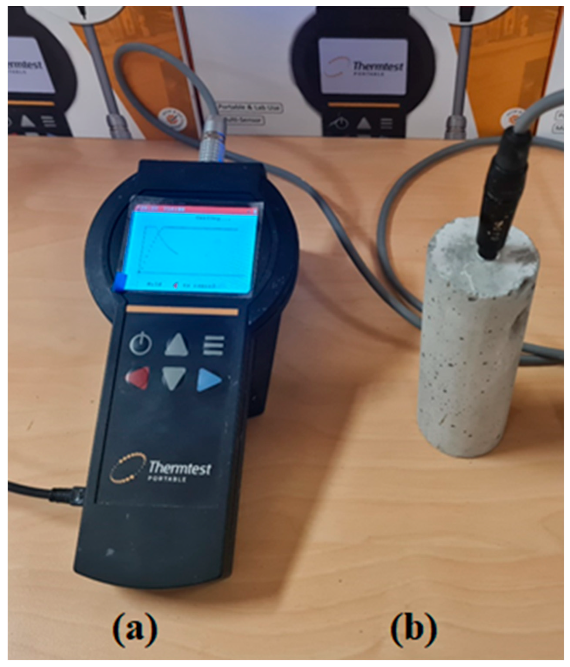
2.2.1. Thermal Conductivity

The thermal conductivity of the developed panels was measured using TLS-100 (transient line source) from Thermtest [43], as shown in Figure 3. This portable meter measures thermal conductivity following ASTM D5334 standards and is appropriate for soil, rock, concrete, and polymer. In addition, the measurement accuracy (±5%) and range (0.1 to 5 W/m·K) of this meter made it suitable for this study. To measure the thermal conductivity, wet mixtures of each panel were poured into a 50 mm diameter and 120 mm long cylinder and cured in an environmental chamber at temperature and relative humidity of 23 °C and 50%, respectively. Then the cured samples were drilled to insert the 100 mm long needle sensor fully into the specimen, as shown in Figure 3. Thermal paste was used to ensure close contact between the sensor and the concrete specimen. Each measurement took approximately 3 min, after which the results for thermal conductivity and thermal resistivity were displayed on the meter. The results were then exported to a computer via USB connections.

2.2.2. Latent Heat Storage

The established method of measuring latent heat storage of a material is differential scanning calorimetry (DSC). However, DSC has limitations in measuring the latent heat storage of heterogeneous materials such as the panels developed in this study. This is due to the very small sample size used in DSC analyzer. Therefore, the latent heat storage of the developed panels was calculated using Equation (2) [44].
h C C = m F S P C M h F S P C M m w + m O P C + m S + m F S P C M  
where m w ,     m O P C ,     m S ,   and   m F S P C M   denote mass of water, OPC, sand, and FSPCM composites, respectively. The hCC and h F S P C M are the latent heat storage of developed panels and FSPCM composites, respectively. The latent heat storage of FSPCM composites were calculated using DSC. Five grams of FSPCM composites were encapsulated in a hermetically tight capsule. Thermal cycling was performed between 15 °C and 45 °C at a ramp of 5 °C/min.

2.3. Operational Energy and Thermal Performance of Developed Panels

This study adopted a numerical modeling approach to calculate the operational Energy and thermal performance of the developed panels. A typical Victorian house was selected for the modeling study because it represents 80% of detached houses in Australia [25,45]. Figure 4 shows the floor plan of the selected house that is north-oriented. According to the Australian Building Code Board (ABCB), this house plan is one of the eight houses selected for energy-efficient star rating platform development in Australia [46]. The house has a gross floor area of 290 m2, including four bedrooms, two bathrooms, a kitchen/family room, a rumpus room, laundry, and a double garage, as seen in Figure 4. The thermo-physical properties of the construction materials used in this case study buildings are given in Table 2. Table 3 shows the measured thermo-physical properties of the developed concrete panels using the methodology described in Section 2.2.
The developed concrete panels were applied to external walls in five different ways to understand the influence of its properties, location and the presence other wall components on the operational energy consumption and overheating of the building. The ceiling and internal wall in each case were constant. The ceiling includes a plasterboard and R4.0 insulation. The internal wall consists of plasterboards on two sides with an air gap in the middle. Figure 5 illustrates the five simulation cases investigated in this study. In each case, the one with normal concrete panel (NCP) was considered as the reference case.
Building simulation software EnergyPlus v9.3 was used to simulate the case study house to determine overheating risk and operation energy consumption considering passive and active houses, respectively [47]. The present authors’ previous studies validated the model house [25]. In addition, the results of the simulated house were validated with experimental observation and analytical outcomes in several relevant studies [48,49]. A conduction finite difference algorithm and convective heat transfer model were used to simulate heat transfer through a building envelope exposed to the sun. The ground surface heat transfer was determined using the GroundHeatTransfer: Slab module. The heating and cooling energy consumption were simulated using the ideal load HVAC template object considering thermostat settings of 20 °C and 24 °C, respectively. The Australian housing energy star rating guideline was followed to schedule standard HVAC system operation. To calculate the internal heat gain, four occupants were considered with different metabolic rates depending on the activity following ASHRAE 55 standard. In addition, the lighting and electric equipment loads of 2.5 W/m2 and 1.875 W/m2, respectively, were considered. The house was occupied by 4 people with a metabolic rate of 108 W/m2 for writing, seating, reading, relaxing, and standing and 171 W/m2 for cleaning and cooking [50]. Further details of the simulation parameters can be found in [25]. The total window area is assumed as 25% of the total floor area complying with ABCB [51]. The properties of single-glazed aluminum-framed windows are given in Table 4 [52]. The window blinds were used for shading when indoor air temperature increased above 26.5 °C and the incident radiation on the window surface was higher than 200 W/m2. The infiltration was considered to be around 0.6 ACH [50]. The window was opened when the outdoor air temperature was between 18 °C and 26.5 °C. The climatic conditions of the extreme heatwave period of 2009 were used to calculate overheating risk in a case study dwelling [25,46]. The overheating risk was calculated using discomfort index proposed by [53].
The EnergyPlus model requires temperature vs. enthalpy graph of PCM integrated panels to simulate the thermal behaviors of PCM. In this study, the HRSP1, HRSP2, and TESP includes FSPCM composites. The temperature vs. enthalpy graph of those panels were generated from measured specific heat capacity data and presented in Figure 6a. Figure 6b shows the measured specific heat capacity of developed panels with and without the FSPCM composites.

2.4. Life Cycle Cost Analysis of Developed Panels

Life cycle cost analysis is used to determine the costs/benefits of retrofit and refurbishment measures introduced in the building considering the integration of thermal energy storage systems and materials. LCC estimates the present value of energy cost over the expected building lifetime, considering the energy cost inflation rate and market discount rate [54]. The actual energy cost was calculated by multiplying the annual energy cost by the present worth factor (PWF), as follows [55].
P 1 = P W F = 1 + r L T 1 r   1 + r L T ,     i f   i > g                             r = i g 1 + g     i f   i < g                           r = g i 1 + i    
P 1 = P W F = L T   1 + i   ,                   i = g  
where i, d and LT show the energy cost inflation rate (9%), discount rate (8.5%), and the lifetime of a building (20–40 years) [54]. Hence, life cycle energy cost (LCEC) was calculated using Equation (5).
L C E C = E C r e f E C r e t ·   P W F
where E C r e f   and   E C r e t   denote operation energy cost of reference and retrofitted building, which are calculated using Equations (6) and (7), respectively.
E C r e f = C L o , r e f C O P · U e l + H L o , r e f ɳ · L H V N G · U n g
E C r e t = C L o , r e f C O P · U e l + H L o , r e f ɳ · L H V N G · U n g
where Uel and Ung represent unit electricity cost (0.31 AUD/kWh) and natural gas consumption cost (0.115/kWh) [25]. LCC of the retrofitted building was calculated using Equation (8).
L C C = E C r e f E C r e t ·   P W F + I r e t I r e f
where Iref and Iret denotes initial investment in reference and retrofit houses, which were calculated by Equations (9) and (10), respectively.
I r e f = i = 1 N m · C n + a = 1 A A · C a + u = 1 U n · C u
I r e t = I r e f + m · C r e t
The payback period (PP) was calculated considering interest and inflation rate as follow [56]:
P P = ln 1 + r I r e t I r e f E C r e f E C r e t l n   1 1 + r

3. Results and Discussion

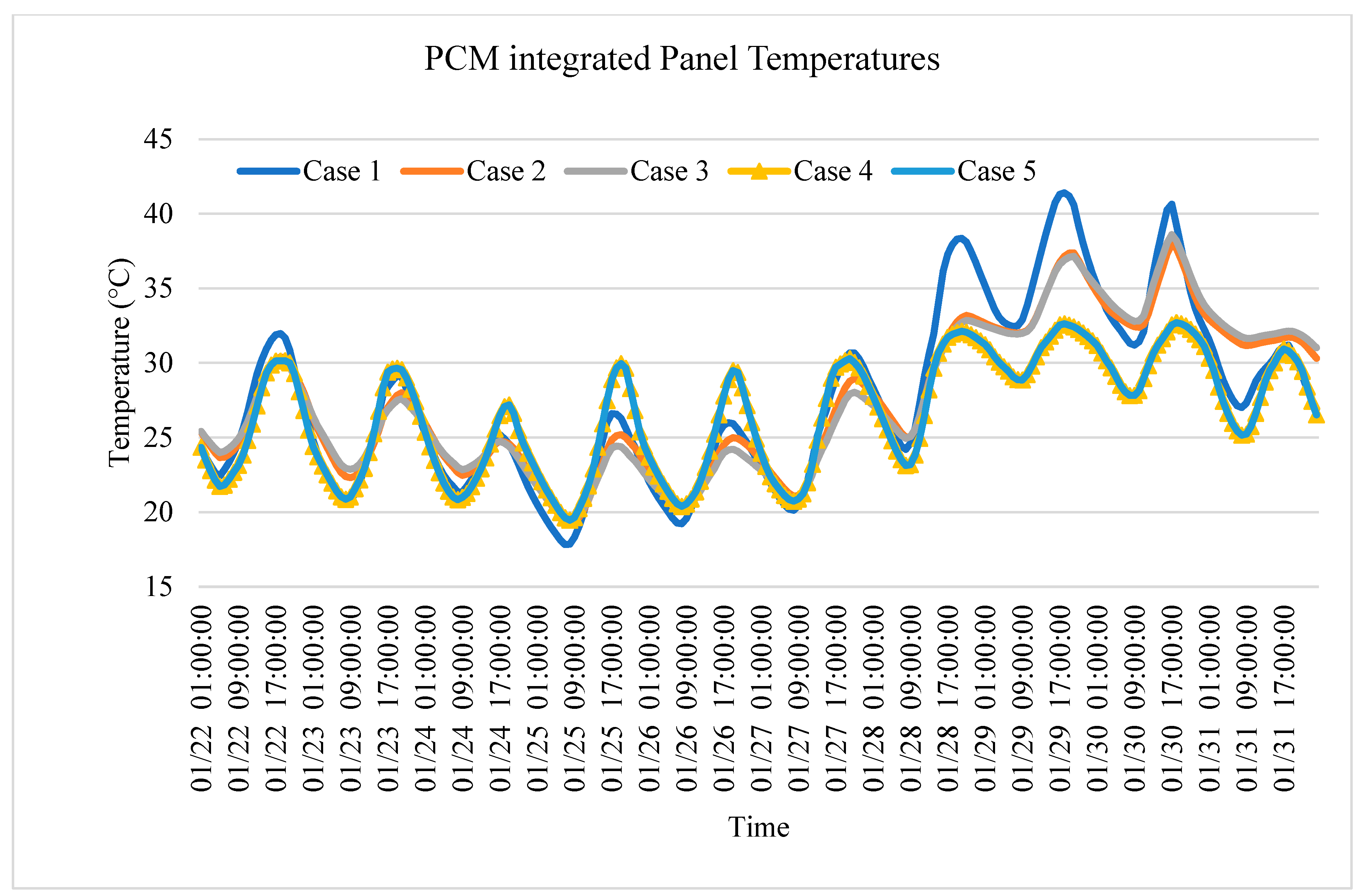
3.1. Impact of Developed Panels on Indoor Overheating

The living zone experienced the highest number of severe thermal discomfort hours in the studied house. Hence, the number of severe discomfort hours of the living zone was used for the comparative analysis. Figure 7 shows the impact of external wall thermal mass on severe discomfort hours for five cases with six developed panels. In most cases, the number of severe discomfort hours in the living zone was higher when SAGP was used and was lower when TESP was used. This was because SAGP had the lowest thermal mass among the developed panels in each case, and TESP had the highest thermal mass. For all cases, a decreasing trend in severe discomfort hours was observed with increasing thermal mass, which was expected. However, the rate of decrease in the number of severe discomfort hours was different in different cases. Cases 4 and 5 exhibited a steeper decrease in the number of discomfort hours with increasing thermal mass. In these cases, the developed panels were placed closer to the indoor environment replacing the plasterboard. As a result, they significantly influenced the indoor thermal condition. However, the comparison of cases 4 and 5 for the number of severe discomfort hours revealed that the presence of external wall insulation (see case 4 and 5 in Figure 5) did not have any significant impact on the decrement rate of the number of severe discomfort hours with thermal mass. Cases 2 and case 3 had similar external wall construction except for the fact that the air gap in case 2 was replaced by R2.0 insulation in case 3. This insulation layer flattened the decreasing rate of severe discomfort hours in case 3 compared to case 2. Hence, the thermal mass has a lower influence on indoor thermal environment when placed between the insulation and the outdoor environment. Because of having the highest thermal mass, TESP was found to have the lower number of severe discomfort hours in all cases except case 1, where HRSP1 had a lower number of discomfort hours. This was probably because the panels were placed close to the outdoor environment on the outer face of 0.11 m thick brick veneer in this case. The brick cladding also had high thermal and hence additional thermal mass of TESP compared to HRSP1 and did not have an impact. Rather, the higher thermal resistance of HRSP1 contributed to a lower number of severe discomfort hours in this case.
Figure 8 shows the impact of external wall thermal resistance on the number of severe discomfort hours for all cases with developed panels. Unlike thermal mass, the relationship between thermal resistance and the number of severe discomfort hours does not follow a pattern. An increase in wall thermal resistance does not necessarily decrease the number of severe discomfort hours. In most cases, NCP, REGP, and SAGP resulted in a similar number of discomfort hours, although the resistance of NCP is much lower than REGP and SAGP. The number of severe discomfort hours for TESP was lower in most cases, although its resistance was lower than SAGP and REGP. This was because of the higher thermal mass of TESP panels as mentioned before. The combined number of severe discomfort hours for all cases has been plotted against corresponding resistance and thermal mass in Figure 9. The figure shows that the relationship between external wall thermal mass and the number of severe discomfort hours is more prominent than the relationship between the number of severe discomfort hours and external wall thermal mass irrespective of the position of the panels. Hence, increasing the thermal mass of the external wall can help to reduce the number of severe discomfort hours. Overall, TESP was found to be the best panel to reduce the number of severe discomfort hours in all cases because of its highest thermal mass, although its thermal resistance is much lower than the other panels.

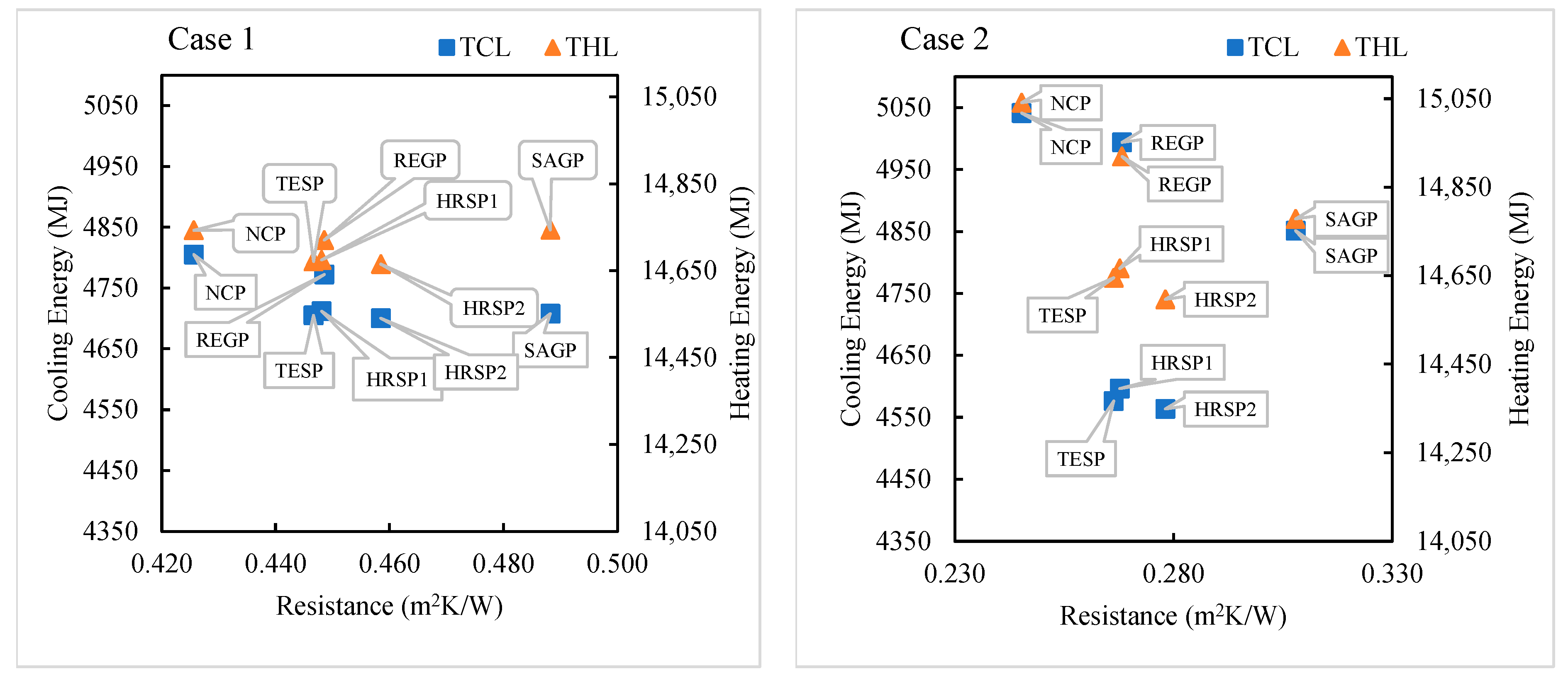
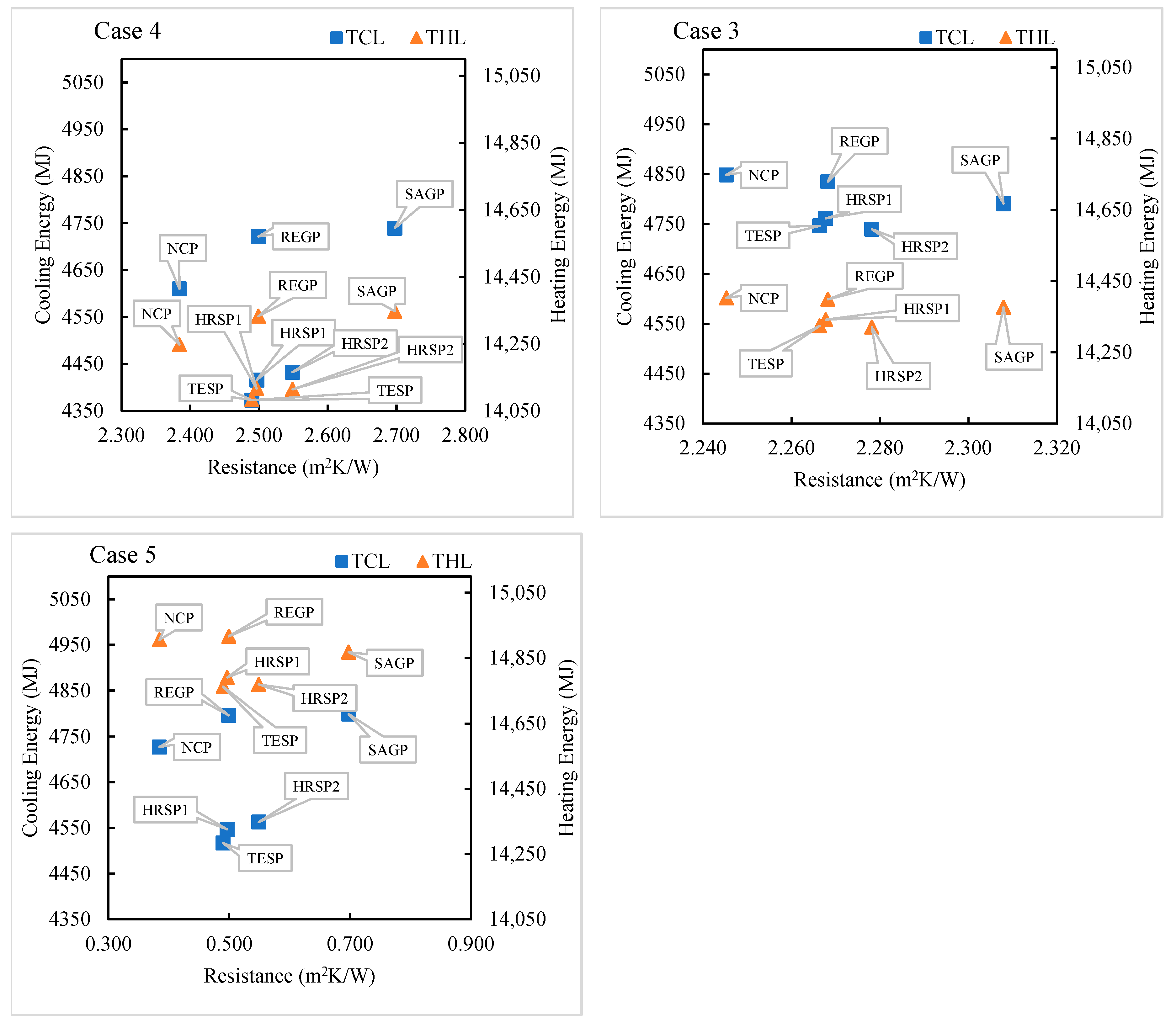
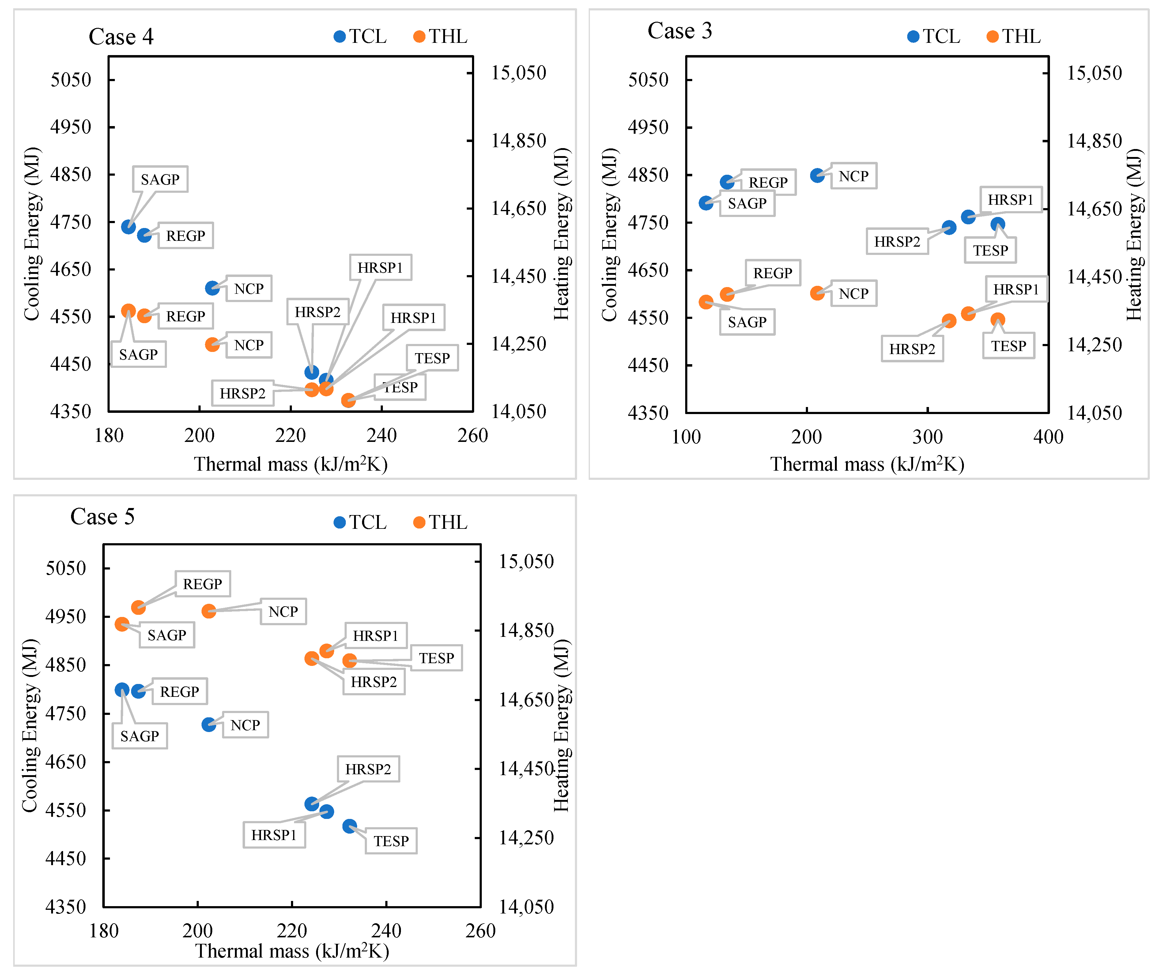
3.2. Impact of Developed Panels on Heating and Cooling Energy Savings

Figure 10 shows the heating and cooling energy savings rates of all developed panels compared to the reference. In each case (as shown in Figure 5), the heating and cooling energy consumption with NCP was considered the reference for % savings calculation. Overall, the panels with FSPCM resulted in higher cooling and heating energy savings compared to the panels without PCM. It is evident from the figure that the energy savings rate varies depending on the location of the panels in the external wall. Case 2 showed the highest heating and cooling energy savings when NCP was replaced with other developed panels. On the other hand, cases 1 and 3 show the lowest energy savings rate. In case 2, the developed panels were used as 0.1 m thick cladding replacing the brick veneer cladding. Hence, the panels in case 2 have a higher amount of PCM compared to the other cases, which contributed to higher savings rates. However, case 3 is also the same as case 2 except it has R2.0 insulation instead of the air gap in case 2. The presence of this insulation layer between indoor environment and the developed panels in the external walls significantly reduced the energy savings rate. However, a comparison of case 4 and case 5 results revealed that if the insulation layer is placed between the developed panels and outdoor environment, and the developed panels are placed close to the indoors (case 4), the presence of insulation does not have a significant impact on the energy savings rate. The energy savings rate was lowest for REGP, which has the second lowest thermal mass and medium resistance level among the six studied panels. Despite having the highest resistance (Figure 11), the heating and cooling energy savings rates of SAGP were much lower than the HRSP1, HRSP2, and TESP due to the lowest thermal mass of SAGP, as shown in Figure 12. Among the panels integrated with FSPCM, HRSP2 was found to be the best option in cases 1, 2, and 3, whereas TESP was the best for case 4 and case 5. HRSP2 has higher resistance (lower conductivity) and lower thermal mass compared to TESP. In cases 1, 2, and 3, the panels were placed close to the outdoor environment where the thermal mass has lower interaction with the indoor environment. In addition, case 1 also includes brick veneer as cladding, which also has high thermal mass. As a result, the additional thermal mass of TESP did not have an impact. Rather, the higher resistance of HRSP2 was effective in reducing the energy consumption. In cases 4 and 5, TESP was more effective in reducing the heating and cooling load due to having higher thermal mass and being close to the indoor environment where it had much greater interaction with the indoor environment. As a result, the relatively lower thermal resistance of TESP compared to HRSP2 did not have an impact.
Figure 11 and Figure 12 show the calculated heating and cooling energy consumption for all developed panels in each case, corresponding to external wall resistance and thermal mass, respectively. In case 1, the heating and cooling energy consumption were decreased slightly with an increase in resistance and thermal mass of the external wall. In this case, the developed panels were applied as a render on the outside face of the brick veneer cladding. The brick veneer already had a relatively low thermal conductivity and medium thermal storage. As a result, a slight increase in resistance did not have much impact on energy savings. Moreover, thermal mass of the developed panels had smaller influence on energy savings because of being close to the outdoor environment.
As mentioned before, case 2 and case 3 have similar external wall structures except for the fact that case 3 has an R2.0 insulation layer in place of the air gap in case 2. However, the pattern of heating and cooling energy consumption was significantly different. In case 3, the heating and cooling energy consumption was insensitive to the resistance and thermal mass of the developed panels. However, in case 2 (Figure 11), an increase in resistance was found to decrease the heating and cooling energy consumption except in the case of SAGP. The heating and cooling energy consumption of SAGP is higher than other panels in this case, although it has the highest resistance. This is due to the low thermal mass of SAGP. Case 2 in Figure 12 shows that heating and cooling energy consumption increases with thermal mass first and then decreases. REGP and NCP have much lower resistance than SAGP, although thermal mass was higher for the former cases. HRSP1, HRSP2, and TESP have much higher thermal mass than the other panels and hence resulted in lower energy consumption. Overall HRSP2 was found to be the best option for case 2 because of its second lowest resistance and second highest thermal mass.
Cases 4 and 5 in Figure 12 show that an increase in thermal mass reduces both heating and cooling energy demand. However, it is evident that the rate of decrease was much steeper in case of cooling energy compared to heating energy. Hence, it can be said that thermal mass helps to reduce cooling energy consumption more than the heating energy consumption. Additionally, case 4 has an insulation layer in place of the airgap in case 5. The presence of this insulation did not have a significant impact on heating and cooling energy consumption rate. This contrasts with the observations for cases 2 and 3. Hence, in the case of an insulated wall, the thermal mass should be added after the insulation, closer to the indoor environment. In case of the non-insulated wall, the thermal mass can be placed close to outdoor environment as well.
Moreover, case 4 and case 5 in Figure 11 show that an increase in resistance does not necessarily reduce the heating and cooling energy consumption. Both in case 4 and case 5, the SAGP has the highest resistance, but the energy consumption was higher compared to other developed panels with PCM. TESP was found to be the most energy efficient panel in case 4 and 5. Figure 13 shows the overall relationship between thermal mass and heating and cooling energy consumption, irrespective of the position of the developed panels on the external wall. The figures show strong correlation between resistance and heating energy consumption compared to the resistance and cooling energy. However, the relationship between cooling energy and thermal mass is more significant than that of heating energy and thermal mass.

3.3. PCM Melting and Solidification Status

Figure 14 shows the temperature of TESP located in the external wall for a period of 10 days during the summer period in Melbourne. It has been assumed that the PCM was melted and solidified when the layer temperature was above and below the PCM melting point of 30 °C. Following that assumption, PCM melted and solidified more frequently in case 4 and case 5 compared to the other cases. This means PCM is more effective when applied close to the indoors.

3.4. Life Cycle Cost and Payback Period of Developed Panels in a Typical Victorian House

Figure 15a shows the life cycle costs (LCC) and payback periods (PBP) of developed panels integrated into building envelopes considering different cases. The cases having 20 mm thick concrete panels are incurred with smaller cost than those case with 100 mm thick concrete panel irrespective of the insulation board. The 20 mm thick HRSP1 is the most economical option for building envelope applications, with the minimum LCC comparable to NCP and the lowest PBP of 1.67–22.12 years. The SAGP and HRSP2 are responsible for higher LCC than reference concrete panels, and their payback period is longer than the building life (40 years), as seen in Figure 15b. No payback period was calculated for REGP and SAGP in case 5 as they resulted in negative energy savings compared to NCP, as shown in Figure 10. Internal application of HRSP1 to an air-gapped and insulated wall produced maximum cost saving with lower PBP than their outside application in the envelope. This is due to the maximum energy savings due to the phase change phenomenon. The economic outcomes agree with the studies regarding economic analysis of phase change material applications in buildings. For instance, Cunha et al. [57] determined energy cost savings of 11% in a typical Portuguese house. Implementing PCM panels in high-rise buildings reduced energy consumption by 27%, resulting in a minimum payback period of 20 years in Shanghai [20]. Oscar et al. [54] determined a PBP of 9.3 years considering the energy savings potential of PCM application in residential buildings in the hot/arid climate of Alice Springs, Australia [54]. Yousra et al. [58] found cooling energy savings of 10% and 3% in earthen and concrete buildings enveloped in an arid and Mediterranean climate with PCM. They calculated a minimum payback period of 23 years. The application of PCM-integrated concrete panels has reduced energy consumption by 28% in the lightweight building, resulting in a minimum payback period of 29 years in Hong Kong. Ali et al. [59] used form-stable phase change material (PCM) composites in a four-person house in NSW with daily energy consumption of 25 kWh. Applying the FSPCM composite reduced annual energy costs by $328, resulting in a payback period of 25 years [59]. This study found minimum payback periods of 16.6 years, 22.5 years, and 24.8 years for form-stable CAHEP-integrated REGP, SAGP, and NCP, respectively, with maximum annual energy savings of 10.5%, 10.3%, and 10.4%, respectively, in a four-person house in Victoria. It should also be noted that the PBP is less when the PCM is added close to the indoors and there is no insulation in the external wall.
The HRSP1 and HRSP2 had a compressive strength of 17.76 MPa and 7.6 MPa, respectively, which was higher than commonly used insulation materials (0.47 MPa) [60] and LWC materials (6.2 MPa) [50]. The compressive strength of TESP was 8.86 MPa [17]. From application perspectives, the HRSP2 and TESP were suitable for plastering because their compressive strength is above the minimum compressive strength required for non-load bearing applications [61]. However, the HRSP1 was suitable for structural application because its compressive strength is comparable for thermally enhanced load-bearing structural applications [62]. In conclusion, the developed panels were structurally suitable for buildings. The compressive strength can be increased further by adding multi-layer graphene [63], which has been shown to have excellent mechanical properties, but it may increase the thermal conductivity of the panel. Further research is recommended to investigate and optimize strength and conductivity.

4. Conclusions and Future Recommendations

This study aimed to investigate the impact of thermal resistance and storage on thermal comfort and energy consumption in a typical Victorian house in temperate oceanic climates. Various concrete panels with different thermo-physical properties were developed using sand, cement, porous materials (SAG, REG, HEP), and capric acid PCM. The thermos-physical properties of each developed panel were measured following appropriate standards and equipment. Then, the thermal and energy-saving performance of those panels was investigated using building simulation software EnergyPlus using a typical Victorian house model. The following are the key conclusions reached from this study:
(1)
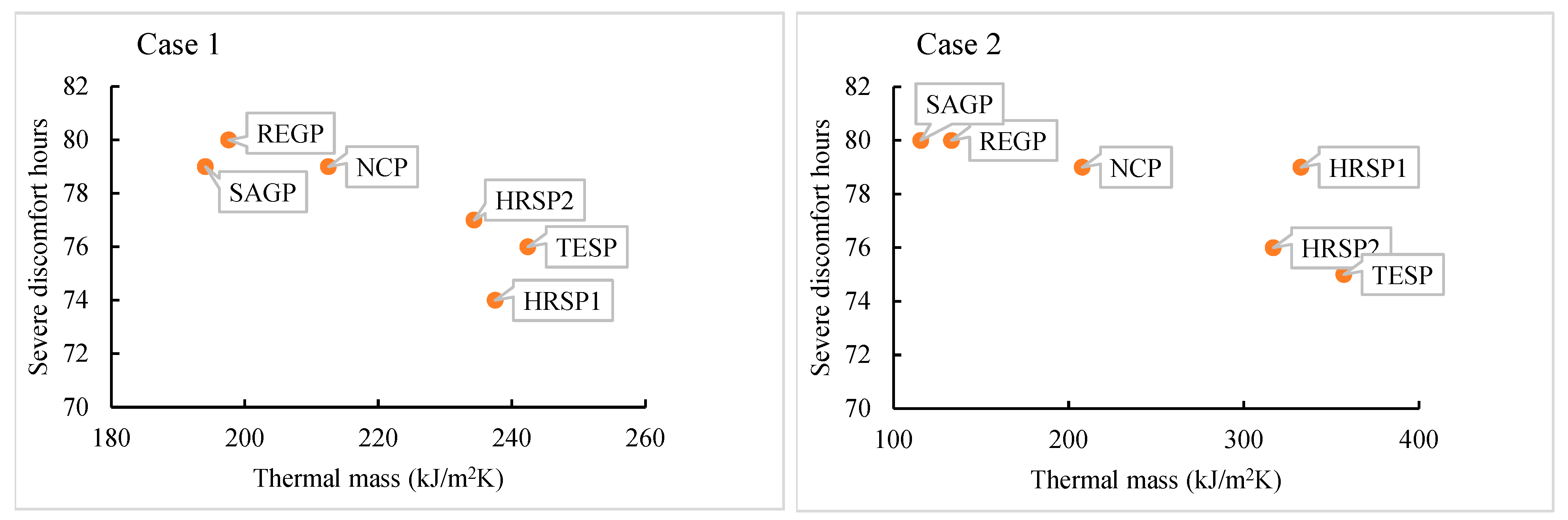
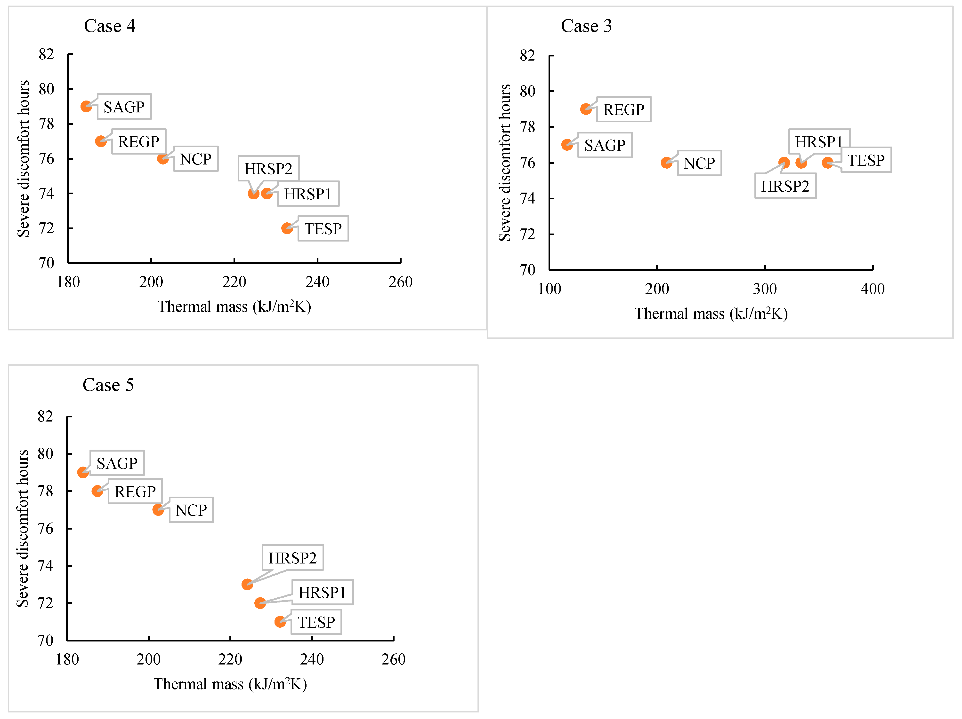
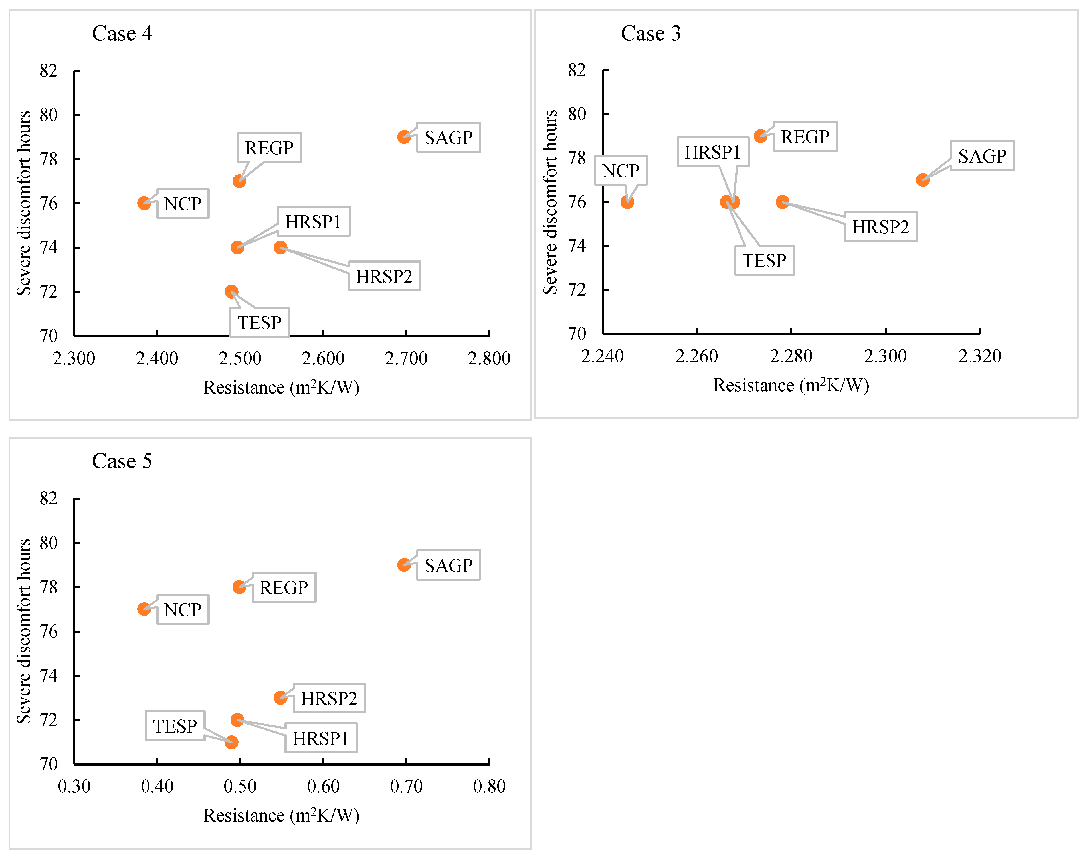
Thermal mass has more influence on severe discomfort hours compared to thermal resistance. However, the thermal mass has a very low influence on severe discomfort hours when placed in an insulated wall between the insulation and outdoor environment. When the thermal mass is placed between the insulation and indoor environment, the presence of insulation has no significant impact on the number of severe discomfort hours. An increase in wall thermal resistance does not necessarily decrease the number of severe discomfort hours.
(2)
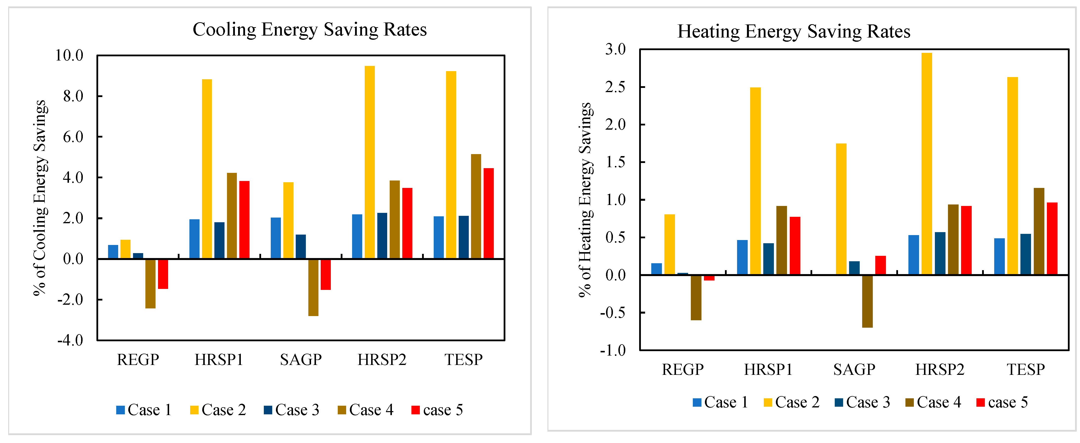
The presence of an insulation layer between indoor environment and the developed panels in external walls also significantly reduces the energy savings rate. When the insulation layer was placed between the developed panels and outdoor environment, and the developed panels were placed close to the indoors (case 4), the presence of insulation did not have a significant impact on energy savings rate.
(3)
In the case of an insulated wall, the thermal mass should be added after the insulation closer to the indoor environment. In the case of a non-insulated wall, the thermal mass can be placed close to outdoor environment as well.
(4)
The resistance is more influential than thermal mass when the panel is placed close to the outdoors. The opposite is true when the panel is placed close to the indoors.
(5)
The heating energy consumption is more influenced by the resistance compared to thermal mass. In contrast, the cooling energy consumption is more influenced by the thermal mass than the resistance. Therefore, a balance is required between these two parameters to make an optimum panel.
(6)
The 20 mm thick HRSP1 is the most economical option for building envelope applications, with the minimum life cycle cost and payback period. The TESP is the next cheapest option after HRSP1. Additionally, TESP was found to be the best panel to reduce severe discomfort hours and energy consumption in most cases. Hence, TESP is considered the best option in terms of cost, energy, and comfort.
In future, this study should be extended to conduct life cycle energy and emission assessment to determine environmental sustainability of thermally enhanced lightweight concrete panels for wall application.

Author Contributions

Conceptualization, formal analysis, writing—review and editing, supervision, M.A.; Conceptualization, methodology, software, writing—original draft preparation, funding acquisition, D.K.; investigation, writing—original draft preparation, A.J.D. All authors have read and agreed to the published version of the manuscript.

Funding

This research was funded by the Higher Education Commission (HEC), Pakistan, with grant number No. 5-1/HRD/HESTPI/(Batch-VI)/6021/2018/HEC.

Data Availability Statement

Some or all data, models, or code generated or used during the study are available from the corresponding author by request.

Conflicts of Interest

The authors declare no conflict of interest.

References

  1. Pérez-Lombard, L.; Ortiz, J.; Pout, C. A review on buildings energy consumption information. Energy Build. 2008, 40, 394–398. [Google Scholar] [CrossRef]
  2. Adilkhanova, I.; Memon, S.A.; Kim, J.; Sheriyev, A. A novel approach to investigate the thermal comfort of the lightweight relocatable building integrated with PCM in different climates of Kazakhstan during summertime. Energy 2021, 217, 119390. [Google Scholar] [CrossRef]
  3. Alassaad, F.; Touati, K.; Levacher, D.; Mendili, Y.E.; Sebaibi, N. Improvement of cob thermal inertia by latent heat storage and its implication on energy consumption. Constr. Build. Mater. 2022, 329, 127163. [Google Scholar] [CrossRef]
  4. Kumar, D.; Alam, M.; Sanjayan, J. Building Adaptation to Extreme Heatwaves. In Engineering for Extremes: Decision-Making in an Uncertain World; Stewart, M.G., Rosowsky, D.V., Eds.; Springer International Publishing: Cham, Switzerland, 2022; pp. 189–216. [Google Scholar]
  5. Sharifi, S.; Saman, W.; Alemu, A. Identification of overheating in the top floors of energy-efficient multilevel dwellings. Energy Build. 2019, 204, 109452. [Google Scholar] [CrossRef]
  6. Tink, V.; Porritt, S.; Allinson, D.; Loveday, D. Measuring and mitigating overheating risk in solid wall dwellings retrofitted with internal wall insulation. Build. Environ. 2018, 141, 247–261. [Google Scholar] [CrossRef]
  7. Baba, F.M.; Ge, H.; Wang, L.; Zmeureanu, R. Do high energy-efficient buildings increase overheating risk in cold climates? Causes and mitigation measures required under recent and future climates. Build. Environ. 2022, 219, 109230. [Google Scholar] [CrossRef]
  8. Cui, K.; Liang, K.; Chang, J.; Lau, D. Investigation of the macro performance, mechanism, and durability of multiscale steel fiber reinforced low-carbon ecological UHPC. Constr. Build. Mater. 2022, 327, 126921. [Google Scholar] [CrossRef]
  9. Lu, D.; Shi, X.; Zhong, J. Understanding the role of unzipped carbon nanotubes in cement pastes. Cem. Concr. Compos. 2022, 126, 104366. [Google Scholar] [CrossRef]
  10. Zhang, H.; Wang, L.; Li, J.; Kang, F. Embedded PZT aggregates for monitoring crack growth and predicting surface crack in reinforced concrete beam. Constr. Build. Mater. 2023, 364, 129979. [Google Scholar] [CrossRef]
  11. Rossi, F.; Castellani, B.; Presciutti, A.; Morini, E.; Filipponi, M.; Nicolini, A.; Santamouris, M. Retroreflective façades for urban heat island mitigation: Experimental investigation and energy evaluations. Appl. Energy 2015, 145, 8–20. [Google Scholar] [CrossRef]
  12. Kumar, D.; Memon, A.G.; Memon, R.A.; Ali, I.; Nord, N. Parametric study of condensation at heating, ventilation, and air-conditioning duct’s external surface. Build. Serv. Eng. Res. Technol. 2018, 39, 328–342. [Google Scholar] [CrossRef] [Green Version]
  13. Kumar, D.; Alam, M.; Memon, R.A.; Bhayo, B.A. A critical review for formulation and conceptualization of an ideal building envelope and novel sustainability framework for building applications. Clean. Eng. Technol. 2022, 11, 100555. [Google Scholar] [CrossRef]
  14. Abbas, H.M.; Jalil, J.M.; Ahmed, S.T. Experimental and numerical investigation of PCM capsules as insulation materials inserted into a hollow brick wall. Energy Build. 2021, 246, 111127. [Google Scholar] [CrossRef]
  15. Kumar, D.; Alam, M.; Sanjayan, J.; Harris, M. Comparative analysis of form-stable phase change material integrated concrete panels for building envelopes. Case Stud. Constr. Mater. 2023, 18, e01737. [Google Scholar] [CrossRef]
  16. Lamrani, B.; Johannes, K.; Kuznik, F. Phase change materials integrated into building walls: An updated review. Renew. Sustain. Energy Rev. 2021, 140, 110751. [Google Scholar] [CrossRef]
  17. Kumar, D.; Alam, M.; Sanjayan, J. An Energy-Efficient Form-Stable Phase Change Materials Synthesis Method to Enhance Thermal Storage and Prevent Acidification of Cementitious Composite. Constr. Build. Mater. 2022, 348, 128697. [Google Scholar] [CrossRef]
  18. Ramakrishnan, S.; Sanjayan, J.; Wang, X. Experimental Research on Using Form-stable PCM-Integrated Cementitious Composite for Reducing Overheating in Buildings. Buildings 2019, 9, 57. [Google Scholar] [CrossRef] [Green Version]
  19. Saffari, M.; de Gracia, A.; Fernández, C.; Cabeza, L.F. Simulation-based optimization of PCM melting temperature to improve the energy performance in buildings. Appl. Energy 2017, 202, 420–434. [Google Scholar] [CrossRef] [Green Version]
  20. Wang, H.; Lu, W.; Wu, Z.; Zhang, G. Parametric analysis of applying PCM wallboards for energy saving in high-rise lightweight buildings in Shanghai. Renew. Energy 2020, 145, 52–64. [Google Scholar] [CrossRef]
  21. Rai, A.C. Energy performance of phase change materials integrated into brick masonry walls for cooling load management in residential buildings. Build. Environ. 2021, 199, 107930. [Google Scholar] [CrossRef]
  22. Ling, Z.; Zhang, Y.; Fang, X.; Zhang, Z. Structure effect of the envelope coupled with heat reflective coating and phase change material in lowering indoor temperature. J. Energy Storage 2021, 41, 102963. [Google Scholar] [CrossRef]
  23. Khalifa, A.J.N.; Abbas, E.F. A comparative performance study of some thermal storage materials used for solar space heating. Energy Build. 2009, 41, 407–415. [Google Scholar] [CrossRef]
  24. de Gracia, A. Dynamic building envelope with PCM for cooling purposes–Proof of concept. Appl. Energy 2019, 235, 1245–1253. [Google Scholar] [CrossRef]
  25. Kumar, D.; Alam, M.; Sanjayan, J.G. Retrofitting Building Envelope Using Phase Change Materials and Aerogel Render for Adaptation to Extreme Heatwave: A Multi-Objective Analysis Considering Heat Stress, Energy, Environment, and Cost. Sustainability 2021, 13, 10716. [Google Scholar] [CrossRef]
  26. Kharbouch, Y.; Ouhsaine, L.; Mimet, A.; El Ganaoui, M. Thermal performance investigation of a PCM-enhanced wall/roof in northern Morocco. Build. Simul. 2018, 11, 1083–1093. [Google Scholar] [CrossRef]
  27. Ahangari, M.; Maerefat, M. An innovative PCM system for thermal comfort improvement and energy demand reduction in building under different climate conditions. Sustain. Cities Soc. 2019, 44, 120–129. [Google Scholar] [CrossRef]
  28. Saxena, R.; Biplab, K.; Rakshit, D. Quantitative Assessment of Phase Change Material Utilization for Building Cooling Load Abatement in Composite Climatic Condition. J. Sol. Energy Eng. 2018, 140, 011001. [Google Scholar] [CrossRef]
  29. Li, M.; Cao, Q.; Pan, H.; Wang, X.; Lin, Z. Effect of melting point on thermodynamics of thin PCM reinforced residential frame walls in different climate zones. Appl. Therm. Eng. 2021, 188, 116615. [Google Scholar] [CrossRef]
  30. Soares, N.; Gaspar, A.R.; Santos, P.; Costa, J.J. Multi-dimensional optimization of the incorporation of PCM-drywalls in lightweight steel-framed residential buildings in different climates. Energy Build. 2014, 70, 411–421. [Google Scholar] [CrossRef]
  31. Ascione, F.; Bianco, N.; De Masi, R.F.; de’ Rossi, F.; Vanoli, G.P. Energy refurbishment of existing buildings through the use of phase change materials: Energy savings and indoor comfort in the cooling season. Appl. Energy 2014, 113, 990–1007. [Google Scholar] [CrossRef]
  32. Adhikary, S.K.; Rudžionis, Ž.; Tučkutė, S. Characterization of novel lightweight self-compacting cement composites with incorporated expanded glass, aerogel, zeolite and fly ash. Case Stud. Constr. Mater. 2022, 16, e00879. [Google Scholar] [CrossRef]
  33. Adhikary, S.K.; Rudžionis, Ž.; Vaičiukynienė, D. Development of flowable ultra-lightweight concrete using expanded glass aggregate, silica aerogel, and prefabricated plastic bubbles. J. Build. Eng. 2020, 31, 101399. [Google Scholar] [CrossRef]
  34. Guardia, C.; Barluenga, G.; Palomar, I.; Diarce, G. Thermal enhanced cement-lime mortars with phase change materials (PCM), lightweight aggregate and cellulose fibers. Constr. Build. Mater. 2019, 221, 586–594. [Google Scholar] [CrossRef]
  35. Kumar, D.; Alam, M.; Sanjayan, J. Experimental and numerical investigation of novel light weight concrete panels made with aerogel and phase change materials. Energy Build. 2023, 283, 112836. [Google Scholar] [CrossRef]
  36. Sukontasukkul, P.; Uthaichotirat, P.; Sangpet, T.; Sisomphon, K.; Newlands, M.; Siripanichgorn, A.; Chindaprasirt, P. Thermal properties of lightweight concrete incorporating high contents of phase change materials. Constr. Build. Mater. 2019, 207, 431–439. [Google Scholar] [CrossRef] [Green Version]
  37. Mokhtari, S.; Madhkhan, M. The performance effect of PEG-silica fume as shape-stabilized phase change materials on mechanical and thermal properties of lightweight concrete panels. Case Stud. Constr. Mater. 2022, 17, e01298. [Google Scholar] [CrossRef]
  38. Wang, F.; Zheng, W.; Qiao, Z.; Qi, Y.; Chen, Z.; Li, H. Study of the structural-functional lightweight concrete containing novel hollow ceramsite compounded with paraffin. Constr. Build. Mater. 2022, 342, 127954. [Google Scholar] [CrossRef]
  39. Kumar, D.; Alam, M.; Sanjayan, J.G. A novel concrete mix design methodology. In Proceedings of The Seventh International Symposium on Nanotechnology in Construction (NICOM7), Monash University, Melbourne, Australia, 31 October–3 November 2022; Shah, S.P., Duan, W., Zhang, L., Eds.; pp. 1–7. [Google Scholar]
  40. Al-Yasiri, Q.; Szabó, M. Numerical analysis of thin building envelope-integrated phase change material towards energy-efficient buildings in severe hot location. Sustain. Cities Soc. 2023, 89, 104365. [Google Scholar] [CrossRef]
  41. Yang, S.; Zhang, Y.; Zhao, Y.; Felipe Torres, J.; Wang, X. PCM-based ceiling panels for passive cooling in buildings: A CFD modelling. Energy Build. 2023, 285, 112898. [Google Scholar] [CrossRef]
  42. Suresh, C.; Kumar Hotta, T.; Saha, S.K. Phase change material incorporation techniques in building envelopes for enhancing the building thermal Comfort-A review. Energy Build. 2022, 268, 112225. [Google Scholar] [CrossRef]
  43. Thermtest. Available online: https://thermtest.com/tls-100 (accessed on 31 January 2023).
  44. Ramakrishnan, S.; Wang, X.; Sanjayan, J.; Petinakis, E.; Wilson, J. Development of thermal energy storage cementitious composites (TESC) containing a novel paraffin/hydrophobic expanded perlite composite phase change material. Sol. Energy 2017, 158, 626–635. [Google Scholar] [CrossRef]
  45. Ramakrishnan, S.; Wang, X.; Sanjayan, J.; Wilson, J. Thermal performance of buildings integrated with phase change materials to reduce heat stress risks during extreme heatwave events. Appl. Energy 2017, 194, 410–421. [Google Scholar] [CrossRef]
  46. Wang, X.; Chen, D.; Ren, Z. Global warming and its implication to emission reduction strategies for residential buildings. Build. Environ. 2011, 46, 871–883. [Google Scholar] [CrossRef]
  47. Crawley, D.B.; Lawrie, L.K.; Winkelmann, F.C.; Buhl, W.F.; Huang, Y.J.; Pedersen, C.O.; Strandd, R.K.; Liesend, R.J.; Fishere, D.E.; J.Wittef, M.; et al. EnergyPlus: Creating a new-generation building energy simulation program. Energy Build. 2001, 33, 319–331. [Google Scholar] [CrossRef]
  48. Amiri Rad, E.; Fallahi, E. Optimizing the insulation thickness of external wall by a novel 3E (energy, environmental, economic) method. Constr. Build. Mater. 2019, 205, 196–212. [Google Scholar] [CrossRef]
  49. Ramakrishnan, S.; Wang, X.; Sanjayan, J.; Wilson, J. Thermal performance assessment of phase change material integrated cementitious composites in buildings: Experimental and numerical approach. Appl. Energy 2017, 207, 654–664. [Google Scholar] [CrossRef]
  50. Kumar, D.; Memon, R.A.; Memon, A.G.; Ali, I.; Junejo, A. Critical analysis of the condensation of water vapor at external surface of the duct. Heat Mass Transf. 2018, 54, 1937–1950. [Google Scholar] [CrossRef]
  51. Alam, M.; Jamil, H.; Sanjayan, J.; Wilson, J. Energy saving potential of phase change materials in major Australian cities. Energy Build. 2014, 78, 192–201. [Google Scholar] [CrossRef]
  52. Ren, Z.; Wang, X.; Chen, D. Heat stress within energy efficient dwellings in Australia. Archit. Sci. Rev. 2014, 57, 227–236. [Google Scholar] [CrossRef]
  53. Epstein, Y.; Moran, D.S. Thermal comfort and the heat stress indices. Ind. Health 2006, 44, 388–398. [Google Scholar] [CrossRef] [Green Version]
  54. Acuña-Díaz, O.; Al-Halawani, N.; Alonso-Barneto, M.; Ashirbekov, A.; Ruiz-Flores, C.; Rojas-Solórzano, L. Economic viability of phase-changing materials in residential buildings–A case study in Alice Springs, Australia. Energy Build. 2022, 254, 111612. [Google Scholar] [CrossRef]
  55. Annibaldi, V.; Cucchiella, F.; De Berardinis, P.; Rotilio, M.; Stornelli, V. Environmental and economic benefits of optimal insulation thickness: A life-cycle cost analysis. Renew. Sustain. Energy Rev. 2019, 116, 109441. [Google Scholar] [CrossRef]
  56. Daouas, N. A study on optimum insulation thickness in walls and energy savings in Tunisian buildings based on analytical calculation of cooling and heating transmission loads. Appl. Energy 2011, 88, 156–164. [Google Scholar] [CrossRef]
  57. Cunha, S.; Aguiar, J.B.; Tadeu, A. Thermal performance and cost analysis of mortars made with PCM and different binders. Constr. Build. Mater. 2016, 122, 637–648. [Google Scholar] [CrossRef]
  58. M’Hamdi, Y.; Baba, K.; Tajayouti, M.; Nounah, A. Energy, environmental, and economic analysis of different buildings envelope integrated with phase change materials in different climates. Sol. Energy 2022, 243, 91–102. [Google Scholar] [CrossRef]
  59. Yousefi, A.; Tang, W.; Khavarian, M.; Fang, C. Development of novel form-stable phase change material (PCM) composite using recycled expanded glass for thermal energy storage in cementitious composite. Renew. Energy 2021, 175, 14–28. [Google Scholar] [CrossRef]
  60. Compressive Strengths of High-Temperature Thermal Insulation. Available online: https://www.jm.com/content/dam/jm/global/en/industrial-insulation/Industrial%20Documents/IND-TB011-Compressive-Strength-of-High-Temperature-Thermal-Insulation.pdf (accessed on 21 February 2023).
  61. Kumar, D. Development of Novel Heat Resistive and High Thermal Energy Storage Lightweight Concrete Panels for Energy Efficient Buildings. Ph.D. Thesis, School of Engineering, Swinburne University of Technology, Hawthorn, Australia, 2023. [Google Scholar]
  62. Berardi, U.; Gallardo, A.A. Properties of concretes enhanced with phase change materials for building applications. Energy Build. 2019, 199, 402–414. [Google Scholar] [CrossRef]
  63. Cui, K.; Chang, J. Hydration, reinforcing mechanism, and macro performance of multi-layer graphene-modified cement composites. J. Build. Eng. 2022, 57, 104880. [Google Scholar] [CrossRef]
Figure 1. Steps of form-stable PCM (FSPCM) preparation.
Buildings 13 00720 g001
Figure 2. Workability of (a) SAGP and (b) HRSP.
Buildings 13 00720 g002
Figure 3. Thermal conductivity (a) datalogger and (b) TLS-100 sensor with test specimen.
Buildings 13 00720 g003
Figure 4. Floor plan of case study buildings.
Buildings 13 00720 g004
Figure 5. Schematic view of building external wall for different simulated cases.
Buildings 13 00720 g005
Figure 6. (a) Enthalpy and (b) specific heat capacity vs. temperature curves of the developed panels.
Buildings 13 00720 g006
Figure 7. The effect of envelope thermal storage on the number of severe discomfort hours in the living zone.
Buildings 13 00720 g007aBuildings 13 00720 g007b
Figure 8. The effect of envelope resistance on the number of severe discomfort hours in the living zone.
Buildings 13 00720 g008aBuildings 13 00720 g008b
Figure 9. Severe discomfort hours with resistance and storage.
Buildings 13 00720 g009
Figure 10. Cooling and heating energy savings rates.
Buildings 13 00720 g010
Figure 11. Effect of external wall thermal resistance on operation energy consumption (cooling and heating).
Buildings 13 00720 g011aBuildings 13 00720 g011b
Figure 12. Effect of external wall thermal mass on operation energy consumption (cooling and heating).
Buildings 13 00720 g012aBuildings 13 00720 g012b
Figure 13. Energy savings with thermal mass and resistance.
Buildings 13 00720 g013
Figure 14. Charging and discharging of TESP layer.
Buildings 13 00720 g014
Figure 15. (a) Life cycle cost (LCC) and (b) payback period of developed panels.
Buildings 13 00720 g015aBuildings 13 00720 g015b
Table 1. Mix design recipe of developed panels.
PanelsCementWaterSandFSPCM CompositesPorous Materials
kg/m3
NCP5202521430--
REGP520252286-194
SAGP520252172-52
HRSP152025217215570
HRSP252025217215521
TESP520252172258-
Table 2. Thermo-physical properties of building materials [25].
Building MaterialsDesign and Thermo-Physical Parameters
Thickness (m)Conductivity (W/m K)Density (kg/m3)Specific Heat (J/kg K)
Concrete0.1001.422400880
Brick veneer0.1100.611690878
Roof insulation0.0440.04412883
Wall insulation0.0440.04412883
Roof tiles0.021.422400880
Ceramic tiles0.012-2000-
Carpet0.020.04651041420
Paint----
Window----
Timber doors0.050.1611221260
Garage door0.03-8000-
Plasterboard0.0130.178471090
Developed concrete panels0.02, 0.1See Table 3See Table 3See Table 3
Note: “Preprinted/adopted with permission from Ref. [25]. 2023, D. Kumar, M. Alam, and Jay Sanjayan”.
Table 3. Thermo-physical properties of thermally enhanced construction materials [15,17].
Developed
Panels
Thermo-Physical PropertiesCost
Density (kg/m3)Conductivity (W/m K)Specific Heat (J/kg K)Melting Point Temperature (oC)Enthalpy (J/g)AUD/m2
NCP22262.27886--9.74
REGP12860.631.09--9.23
SAGP10480.281.51--39.05
HRSP114420.641.7130.0812.6010.83
HRSP212800.481.7830.1914.7223.11
TESP15040.672.1323.9431.4512.29
Note: “Preprinted/adopted with permission from Refs. [15,17]. 2023, D. Kumar, M. Alam, and Jay Sanjayan”.
Table 4. Single-glazed aluminum-framed windows.
DescriptionValues
Thickness0.003 m
Overall heat transfer value5.5 W/(m2-K)
Solar transmittance0.45 (-)
Visible transmittance0.70 (-)
Disclaimer/Publisher’s Note: The statements, opinions and data contained in all publications are solely those of the individual author(s) and contributor(s) and not of MDPI and/or the editor(s). MDPI and/or the editor(s) disclaim responsibility for any injury to people or property resulting from any ideas, methods, instructions or products referred to in the content.

