Abstract
To analyze the seismic response characteristics of unequal-span subway station structures in saturated sites, a three-dimensional numerical model of an unequal-span subway station structure is established, based on the finite element analysis software MIDAS-GTS. The elastic modulus, cohesion, Poisson’s ratio, and friction angle are selected as the sensitivity parameters. Moreover, combined with the saturated two-phase medium dynamic analysis method, the orthogonal test method is also utilized, to obtain the corresponding seismic response range. The results show that, the lower end of the shear wall and the vicinity of the cantilever span are prone to bending failure, and that the central columns are prone to shear failure. Under the action of a horizontal ground motion, or under the combination of horizontal and vertical ground motions, the influence of the elastic modulus is the largest, the influence of the Poisson’s ratio and the friction angle is the second largest, and the influence of cohesion is the smallest. This procedure of seismic response characteristics for unequal-span subway station structures can provide a reference for the seismic design of these structures.
1. Introduction
With the acceleration of urbanization in China, the increase in ground traffic pressure has gradually saturated the means of transportation, so an increasing number of cities have begun to develop underground space. Subway construction is an important part of subway development [,]. While subway stations are convenient for travel and rich in travel modes, they also cause the scale and complexity of the cross-sectional form of the subway station structure to increase. Therefore, an unequal-span underground subway structure, with a wide upper part and a narrow lower part, has become the common selection of future stations in urban subway planning and construction []. Many scholars [,,,,] have studied the seismic response and disaster mechanism, considering soil-structure dynamic interactions, of large subway station structures with traditional rectangular frames, by using different dynamic analysis methods with different types of multilayer and multispan station structures as the research objects. For such complex cross-sectional structures, in particular, there have been few studies on the seismic dynamic response of unequal-span subway stations in saturated sites, and research on the sensitivity of seismic dynamic response parameters is still rare. At the same time, considering that China is an earthquake-prone country, the analysis of seismic dynamic response characteristics of different-span subway station structures in saturated sites, has an important guiding role and practical significance for earthquake prevention and disaster reduction, and seismic design of complex subway station structures [,,,].
To date, many scholars have analyzed and studied subway station structures in terms of the factors influencing their seismic response. Lin et al. [] modeled a subway station by using finite element software, and analyzed the influence of subway depth, soil distribution, and structure type on the seismic performance of the station structure. Taking underground frame structures such as subway stations as an example, Wang et al. [] proposed a method, based on the story drift angle, to examine the deformability of structural components and the effective stress value, to evaluate the strength of structural components. By changing parameters such as the axial force, spring stiffness, and damping coefficient, Huan et al. [] analyzed the structural seismic response of subway stations under different working conditions. Han [] analyzed the influence of the elastic modulus, cohesion, and friction angle on surface settlement, by FLAC 3D finite difference software, with the ground settlement displacement as an index, caused by shield construction of a subway tunnel in a loess region. Cui et al. [] studied the parameter sensitivity of subway station structures under soft soil foundations, by using the dynamic method of two-phase porous media and the method of multi-index comprehensive balance, and then further studied the seismic dynamic response characteristics and disaster mechanism of subway station structures in soft soil. Based on the measured earthquake damage data of tunnels, Wang et al. [] discussed the influence of tunnel geometry and site conditions on the seismic response of structures. Zhuang et al. [] studied the influence of the liquefaction degree of different sites on the seismic dynamic response of subway station structures under earthquake action, by shaking table experiments. Li et al. [] analyzed the variation law of the internal force of subway station structures in saturated soft soil, with different burial depths, under earthquake action. Hu et al. [] used the finite element and finite difference (FE-FD) coupling method, to analyze the influence of buried depth and soil relative density on the liquefaction degree of the site, and the uplifting effect of the structure of the saturated-sand-site subway station structure system. Xia et al. [] studied the effect of ground motion intensity and relative stiffness between soil and structure on the seismic dynamic response of subway station structure, by taking the interstory drift angle as an index. With the tunnel project of Guangzhou Rail Transit Line No. 22 as the research background, Song et al. [] combined the orthogonal experiment method and the finite element method and optimized the bolt-shotcrete support parameters and the thickness of the corrugated steel plate, through range analysis. The safety factor was also checked by the structural internal force, to meet relevant design requirements. Using the background of a section tunnel of Urumqi urban rail transit under a viaduct, Xu et al. [] selected seven influencing factors and nine levels of geotechnical and structural material parameters to establish a simulation scheme, and combined gray correlation analysis and numerical simulation for quantitative research. Wang et al. [,] analyzed the seismic response of unequal-span subway underground station structures under different types of sites. Xu et al. [] used the u-p effective stress formulations of the two-phase media method, to analyze the parameter sensitivity of a one-story subway station with double spans in saturated sand layers. Taking the foundation pit project of Guangzhou Metro Line 11 as an example, He et al. [] studied the effects of support stiffness, burial depth, and thickness of the diaphragm wall, on the maximum horizontal displacement of a diaphragm wall and the maximum horizontal and vertical displacement index of a subway tunnel, by orthogonal testing. Yang et al. [] analyzed the importance order of the effect of various factors on the deformation of underground subway tunnels during excavation of the foundation pit, by using orthogonal sensitivity tests. Wu et al. [] calculated the dynamic response of different unequal-span subway station structures, analyzed the structure failure mechanism, and established the seismic performance evaluation index. The results can help improve the understanding of the failure modes of underground frame structures. Wang et al. [] applied a constitutive model of saturated sand and the ALE method, to analyze the seismic performance and seismic design method for unequal-span subway stations at a liquefaction site, from the liquefaction distribution site, lateral deformation, and earthquake-induced damage of the underground structure. Shatnawi et al. [] studied the behavior of reinforced concrete box culverts with different sizes and thicknesses, under different soil fill heights. Chen et al. [] determined the influence of buried depth variation on the seismic capacity of underground subway stations, in the framework of performance-based seismic design, with a particular focus on the interstory drift ratio limit.
The above studies mostly applied single factor analysis, which can intuitively reflect the impact of various parameters on the benchmark index value, but does not consider the correlation between parameters. However, orthogonal experimental design can achieve the expected and scientific statistical results through fewer tests, in multifactor sensitivity analysis. Therefore, this paper establishes a three-dimensional finite element numerical model of the structural system of an unequal-span subway station in a saturated site, based on MIDAS-GTS. Using saturated two-phase medium dynamic analysis, range analysis, and orthogonal testing of four factors and three levels, the seismic dynamic response characteristics of the unequal-span subway underground station structure are explored. Additionally, the sensitivity of the soil parameters around the subway to internal forces at the structural feature points of the unequal-span subway station, and the relative displacement of the roof and floor under the action of a single horizontal ground motion and the combined action of horizontal and vertical ground motions, are also investigated. The flow chart of the main steps is shown in Figure 1.
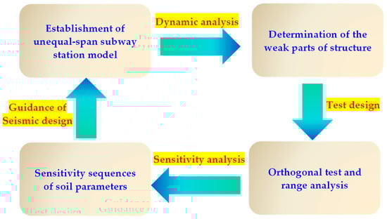
Figure 1.
Flow chart of the main steps.
2. Numerical Model and Orthogonal Test Design
The station is a large and complex unequal-span subway station, with five spans in the upper layer and three spans in the lower layer. The buried depth, height, and width of the upper and lower layers of the station are 3.2 m, 12.53 m, 31.5 m, and 18.7 m, respectively, and the size of the frame columns of each layer is 1.2 m × 0.6 m. To ensure that the dynamic calculation results are close to the actual engineering conditions, and avoid the influence of lateral boundary conditions, the soil layer size around the subway is 220.5 m × 40 m. The cross-sectional characteristics and detailed dimensions of the subway structure are shown in Figure 2, and the structural model of the cross-span subway underground station is shown in Figure 3. The distributions of soil parameters and station structure parameters are shown in Table 1.
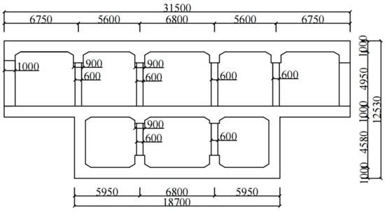
Figure 2.
Cross-sectional view of the subway station structure (mm).
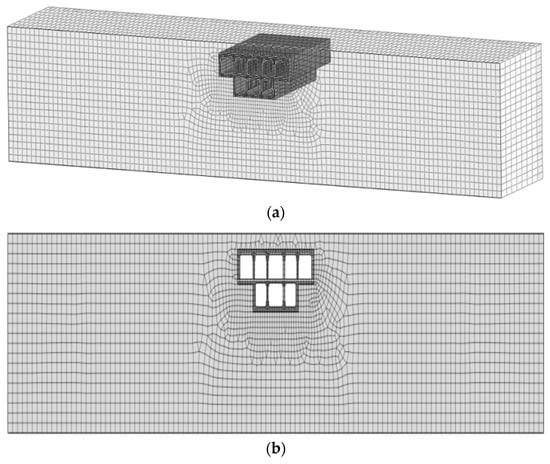
Figure 3.
Structural model of unequal-span subway station. (a) Three-dimensional model of the subway station. (b) Section of the subway station.

Table 1.
Values of parameters.
The clay property and concrete property are applied to the soil material and concrete material, respectively. The Mohr–Coulomb constitutive model is used for the soil constitutive model around the underground station of the unequal-span subway. The concrete structure is simulated by an elasto-plastic constitutive model. The two sides of the station model are set with the same plane free field boundary, and the bottom end is fixed. The subway station grid is 0.5 m × 0.5 m, and the surrounding soil grid size is 1 m × 1 m. Soil and subway station structure exhibit 5% Rayleigh damping. In this study, the station structure and the soil are completely bonded, without considering the separation and slip between the contact surfaces.
The fluid-solid coupling two-phase media dynamic model, considers the coupling relationship between the dynamic response of the solid phase and the fluid phase in saturated soil, which is an accurate calculation model in theory. The effective stress formulations of two-phase media are shown below [].
Here, M is the total mass matrix, C is the null matrix, Ω is the domain of integration, u is the displacement vector, B is the strain-displacement matrix, is the effective stress tensor, Q is the discrete gradient operator of coupling water and soil particles, p is the pore pressure vector, S is the compression coefficient matrix, and H is the permeability coefficient matrix. Vectors and represent the given boundary conditions for volumetric forces in the soil-water mixture and the liquid phase, respectively.
The Mohr–Coulomb constitutive model demonstrates comprehensive, reliable, and reasonable performance, so it is widely used in geotechnical engineering by researchers [,]. The yield surface function of the Mohr–Coulomb constitutive model is shown in Equation (3) [].
In Equation (3), is the inclination angle of the Mohr–Coulomb yield surface on the stress plane, as shown in Figure 4, and is called the friction angle of the material, where , is the cohesion of the material, and according to the following formula, controls the shape of the yield surface in the -plane.
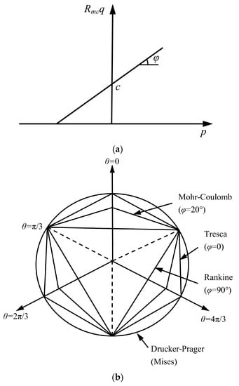
Figure 4.
Yield surface of the Mohr–Coulomb model. (a) Mohr–Coulomb yield surface on the π surface. (b) Comparison of the Mohr–Coulomb yield surface with other constitutive yield surfaces.
In Equation (4), is the polar angle, and the definition formula is . r is the third deviatoric stress invariant . The shape of the Mohr–Coulomb yield surface on the plane is shown in Figure 4. The relationship between the Mohr–Coulomb yield surface and other constitutive yield surfaces is also shown in Figure 4.
As the energy consumption of underground structures is related to the duration of earthquakes, the longer the underground structure is subjected to vibration, the more energy it consumes. Considering that the fundamental period of the structural vibration of the unequal-span subway station is 1.52 s and the duration of ground motion is generally five to ten times the fundamental period [], the duration of the earthquake is taken as 15 s in this paper. The input directions are the horizontal input and horizontal and vertical input. The horizontal and vertical input seismic waves are adjusted based on the El Centro seismic wave [], as shown in Figure 5.
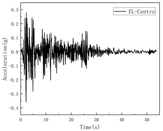
Figure 5.
Acceleration–time history curve of the El Centro earthquake wave.
Orthogonal experimental design is a multifactor experimental approach based on the fractional principle of factor design, which arranges design experiments using orthogonal tables derived from combinatorial theory and performs statistical analysis and design based on the results []. In multifactor experiments, when the number of factors and levels increases, the number of experimental treatments increases dramatically if a full-scale trial is performed, and it is difficult to schedule all treatments in a single trial. To solve these problems, it is necessary to select some highly representative treatment combinations to perform the experiments, which can generally be determined by orthogonal tables. These treatments are usually orthogonal points in linear space.
In this paper, a test refers to a numerical simulation computed under a given set of physical parameters of the soil, with the same simulation steps. The purpose of designing the test scheme, is to determine the influence of each parameter on the test index, through fewer simulation calculations. In this paper, the elastic modulus, cohesion, Poisson’s ratio, and friction angle of clay are selected as factors. To reduce the number of experiments as much as possible, the scheme is designed using orthogonal tables with three factors and four levels, resulting in a total of nine simulation experiments. The tables of factor level and test design are shown in Table 2 and Table 3, respectively.
Table 2.
Levels of factors.
Table 3.
Test design.
3. Seismic Dynamic Response Analysis of an Unequal-Span Subway Station Structure
Facilitating the dynamic response and sensitivity analysis, the characteristic points of the unequal-span subway station structure are selected, as shown in Figure 6. The maximum axial force, shear force, and bending moment data of the characteristic points of the subway station structure under horizontal ground motion and working condition 1 (i.e., the elastic modulus, cohesion, Poisson’s ratio, and friction angle of clay, are 5 × 10⁴ kPa, 18 kPa, 0.3, and 20°, respectively), are shown in Figure 7.
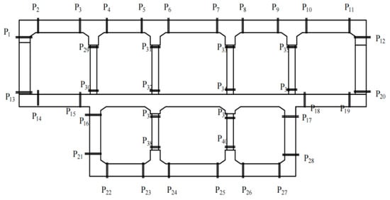
Figure 6.
Distribution of feature points of the subway station structure.
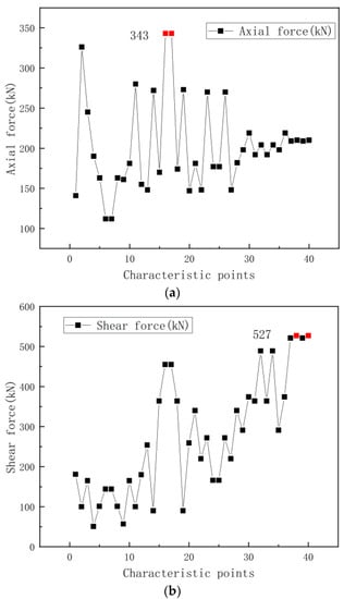
Figure 7.
Maximum internal force of the characteristic points of the subway station structure. (a) Maximum axial force of the subway station structure. (b) Maximum shear force of the subway station structure. (c) Maximum bending moment of the subway station structure.
As shown in Figure 7, the maximum internal force of the unequal-span subway station structure is symmetrically distributed along the axis of the structure. At the same time, the maximum axial force, maximum shear force, and maximum bending moment in the subway station structure are located near the overhang span (feature points and ), the lower frame column (feature points and ), and both ends of the bottom plate (feature points and ).
In the subway station structure, for the vertical members, the amplitude of the upper shear wall of the subway station is close to 90.90% of the maximum bending moment amplitude of the subway station structure, the lower shear wall is close to 94.32% of the maximum bending moment level, the upper level of the lower column is close to 98.86% of the maximum shear level of the structure, and the lower shear amplitude of the upper middle column is close to 92.79% of the maximum shear level of the subway station structure. In summary, in the structure system of the unequal-span subway station under earthquake action, the lower end of the shear wall and the cantilever span of the station structure are prone to bending failure, and the upper middle column and lower column of the station structure are prone to shear failure. These locations are weak parts of stress failure. Therefore, in the future design of such subway station structures, attention should be given to these issues.
4. Parameter Sensitivity Analysis of the Seismic Dynamic Response Index of Unequal-Span Subway Station Structure
Figure 7 shows that the dynamic response of the unequal-span subway station structure is symmetrical along the axis of the structure. Therefore, this section selects the maximum dynamic internal force response of a single span structure to construct the evaluation index system. The maximum interstory drift ratio, the maximum axial force (feature point ), the maximum shear force (feature point ), and the maximum bending moment (feature point ) of the roof and floor, are selected as the typical indices of the dynamic response of the unequal-span subway station structure. Then, parameter sensitivity analysis is carried out, for the dynamic response index caused by the parameter change in the soil layer around the subway.
Due to the heterogeneity and complexity of the soil, an orthogonal test table is used in this paper, to record the data []. Reference [] shows that the main physical parameters of soil affecting the deformation and dynamic response of subway station structures are the friction angle, elastic modulus, cohesion, and Poisson’s ratio. Therefore, in this study, the sensitivity of the dynamic response index parameters of the underground station structure of the unequal-span subway station, to the elastic modulus (range of – kPa), cohesion (range of 18–30 kPa), Poisson’s ratio (range of 0.3–0.5), and friction angle (range of 18°–25°) of the soil layer parameters around the subway, is analyzed. The design of the four factors and three-level orthogonal test program, and the corresponding conditions, typical indicators of dynamic response values, are shown in Table 4.
Table 4.
Dynamic response values under a horizontal transverse earthquake.
Figure 8 shows the range distribution of the maximum internal force and the maximum interstory drift ratio of the structural characteristic points of the unequal-span subway station, under the action of horizontal ground motion. In can be seen from Figure 8, that among the four soil layer parameters, the change in elastic modulus has the most significant effect on the maximum axial force, maximum shear force, maximum bending moment, and maximum interstory drift ratio. The effect of the change in the Poisson’s ratio on the maximum shear force is similar to that of cohesion. In particular, the change in cohesion has little effect on the maximum shear force, maximum bending moment, and maximum interstory drift ratio of the roof and floor, which indicates that cohesion is the least sensitive parameter among the four soil parameters under the action of a single, horizontal and lateral ground motion. Furthermore, the ground motion changes from a single horizontal motion, to the combined action of horizontal and vertical motions. Table 5 shows the dynamic response value of the unequal-span subway station structure, under the combined action of the horizontal and vertical motions.
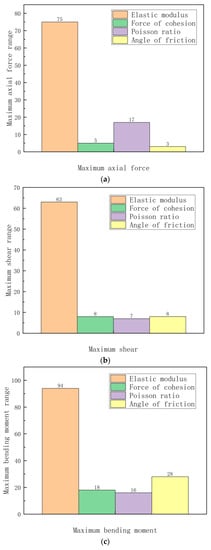
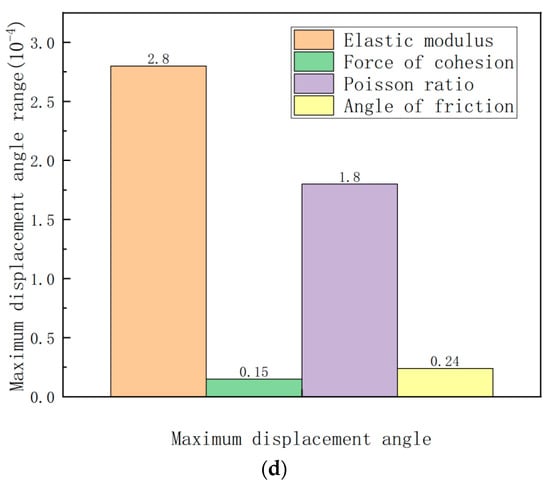
Figure 8.
Range of the structural dynamic response index corresponding to the variation in soil parameters. (a) Maximum axial force range of the feature points. (b) Maximum shear range of the feature points. (c) Maximum bending moment range of the feature points. (d) Maximum displacement angle range of the feature points on roof and floor.
Table 5.
Dynamic response values under horizontal and vertical earthquakes.
Figure 9 shows the range distribution of the maximum internal force, and the maximum roof-to-floor displacement angle of the structural characteristic points of the unequal-span subway station, under the combined action of horizontal and vertical ground motions. As seen in Figure 8, among the four soil parameters, the change in elastic modulus has the most significant influence on the maximum axial force, maximum shear force, and maximum bending moment. The change in the Poisson’s ratio has the most obvious effect on the maximum displacement angle of the roof and floor, and its effect on the maximum shear force is similar to that of the friction angle. In particular, the change in cohesion has little influence on the maximum shear force, the maximum bending moment, and the maximum displacement angle of the roof and floor, which indicates that cohesion has the least influence among the four soil parameters, under the combined action of horizontal and vertical ground motions.
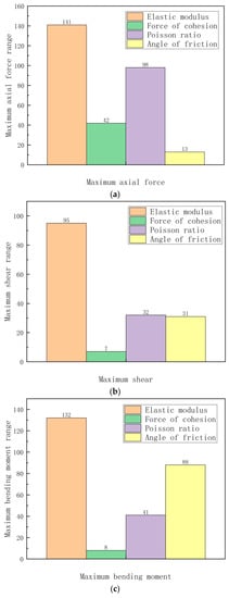
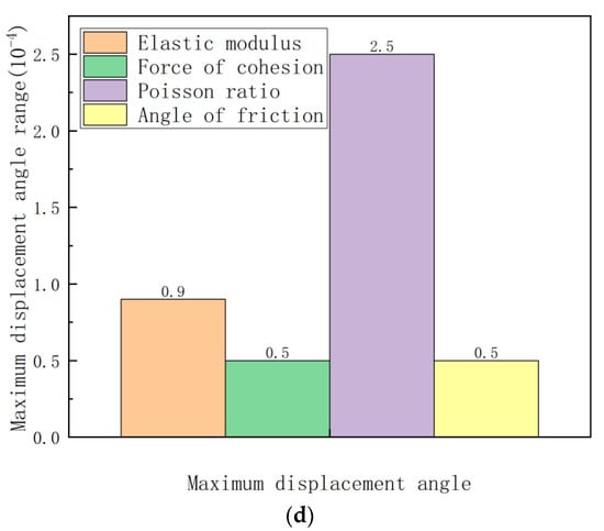
Figure 9.
Range of the structural dynamic response index corresponding to the variation in soil parameters. (a) Maximum axial force range of the feature points. (b) Maximum shear range of the feature points. (c) Maximum bending moment range of the characteristic points. (d) Maximum displacement angle range of the characteristic points on the roof and floor.
5. Conclusions
In this paper, the seismic response characteristics and parameter sensitivity of an unequal-span subway station structure system in a saturated site are analyzed, based on an orthogonal test design scheme of four factors and three levels, which considers the coupling relationships between multiple factors. The main conclusions are as follows:
- (1)
- Under the action of an earthquake, the lower end of the shear wall and the vicinity of the cantilever span of the unequal-span subway station structure in the saturated site, are prone to bending failure, and the central columns of the station structure are prone to shear failure. All of them are weak components of the structure, with the accumulation of stress damage.
- (2)
- Comparing the range of soil parameters on the dynamic response of the unequal-span subway station structure under the action of a single horizontal or combination of horizontal and vertical ground motions, it is clear that the elastic modulus has the greatest impact on the dynamic response of the unequal-span subway station structure, followed by the Poisson’s ratio and friction angle, and the sensitivity of cohesion has the least influence.
These research results can be adopted to guide the seismic design and seismic reliability analysis of unequal-span subway station structures. However, it should be noted that the randomness of ground motions was ignored in this paper. This is of high significance for further work on the influence of earthquake uncertainty on the seismic performance of unequal-span subway station structures.
Author Contributions
Conceptualization and methodology, J.S.; software, C.C., W.X. and L.L.; validation, J.S., M.X., W.X. and J.Z.; data curation, W.X.; writing—original draft preparation, J.S.; writing—review and editing, C.C.; supervision, C.C. and L.L.; funding acquisition, C.C. All authors have read and agreed to the published version of the manuscript.
Funding
This research was funded by the National Natural Science Foundation of China (grant no. 51578100), and special funds for the basic scientific research expenses of central government universities (grant no. 3132019349).
Institutional Review Board Statement
Not applicable.
Informed Consent Statement
Not applicable.
Data Availability Statement
The data reported in this article are available from the corresponding author upon request.
Conflicts of Interest
The authors declare no conflict of interest.
References
- Cui, C.; Xu, M.; Xu, C.; Zhang, P.; Zhao, J. An ontology-based probabilistic framework for comprehensive seismic risk evaluation of subway stations by combining Monte Carlo simulation. Tunn. Undergr. Space Technol. 2023, 135, 105055. [Google Scholar] [CrossRef]
- Yuan, B.; Li, Z.; Zhao, Z.; Ni, H.; Su, Z.; Li, Z. Experimental study of displacement field of layered soils surrounding laterally loaded pile based on transparent soil. J. Soils Sediments 2021, 21, 3072–3083. [Google Scholar] [CrossRef]
- Wang, J.; Ma, G.; Dou, Y.; Zhuang, H.; Fu, J. Performance levels and evaluation method for seismic behaviors of a large-scale underground subway station with unequal-span frame. J. Vib. Shock 2020, 39, 92–100. [Google Scholar] [CrossRef]
- Tang, X.; Fu, P.; Li, H.; Gong, J. Seismic simulation and analysis of the two-layer prestressed long-span subway station. J. Northeast. Univ. (Nat. Sci.) 2015, 36, 892–896. [Google Scholar] [CrossRef]
- Tao, L.; Liu, C.; Bian, J.; Wu, B.; Li, J.; Xu, Y. Seismic response of subway station with large span and Y shaped column. Chin. J. Theor. Appl. Mech. 2017, 49, 55–64. [Google Scholar] [CrossRef]
- Wang, J.; Dou, Y.; Zhuang, H.; Fu, J.; Ma, G. Seismic response of dynamic interaction system of soil-diaphragm wall-complicated unequal-span subway station. Chin. J. Geotech. Eng. 2019, 41, 1235–1243. [Google Scholar]
- Cui, C.; Liang, Z.; Xu, C.; Xin, Y.; Wang, B. Analytical solution for horizontal vibration of end-bearing single pile in radially heterogeneous saturated soil. Appl. Math. Model. 2023, 116, 65–83. [Google Scholar] [CrossRef]
- Meng, K.; Cui, C.; Liang, Z. A new approach for longitudinal vibration of a large-diameter floating pipe pile in visco-elastic soil considering the three-dimensional wave effects. Comput. Geotech. 2020, 128, 103840. [Google Scholar] [CrossRef]
- Zhong, Z.; Shen, Y.; Zhao, M.; Li, L.; Du, X.; Hao, H. Seismic fragility assessment of the Daikai subway station in layered soil. Soil Dyn. Earthq. Eng. 2020, 132, 106044. [Google Scholar] [CrossRef]
- Bu, X.; Ledesma, A.; Lopez-Almansa, F. Novel seismic design solution for underground structures: Case study of a 2-story 3-bay subway station. Soil Dyn. Earthq. Eng. 2021, 153, 107087. [Google Scholar] [CrossRef]
- Cui, C.; Meng, K.; Xu, C.; Wang, B.; Xin, Y. Vertical vibration of a floating pile considering the incomplete bonding effect of the pile-soil interface. Comput. Geotech. 2022, 150, 104894. [Google Scholar] [CrossRef]
- Yuan, B.; Chen, W.; Zhao, J.; Li, L.; Liu, F.; Guo, Y.; Zhang, B. Addition of alkaline solutions and fibers for the reinforcement of kaolinite-containing granite residual soil. Appl. Clay Sci. 2022, 228, 106644. [Google Scholar] [CrossRef]
- Lin, L.; Chen, J. Analysis of earthquake-resistant capacity of shallow-buried subway station structures in soft soil. J. Disaster Prev. Mitig. Eng. 2006, 26, 268–273. [Google Scholar] [CrossRef]
- Wang, G.; Yuan, M.; Miao, Y.; Wu, J.; Wang, Y. Experimental study on seismic response of underground tunnel-soil-surface structure interaction system. Tunn. Undergr. Space Technol. 2018, 76, 145–159. [Google Scholar] [CrossRef]
- Huan, Y.; Fang, Q.; Liu, J.; Chen, L.; Du, M. Theoretical and numerical investigations on enhancement of a seismic capability of metro stations. J. Vib. Shock 2011, 30, 252–257. [Google Scholar] [CrossRef]
- Han, X. Formation parameters sensitivity analysis of subway construction in loess region. Shanxi Sci. Technol. Commun. 2012, 4, 50–52+63. [Google Scholar]
- Cui, C.; Cheng, X.; Sun, Z.; Xu, C. Analysis of seismic response and parametric sensitivity of subway station surrounded by saturated soft soil. J. Railw. Eng. Soc. 2017, 34, 92–98. [Google Scholar] [CrossRef]
- Wang, Z.; Zhang, Z. Seismic damage classifcation and risk assessment of mountain tunnels with a validation for the 2008 Wenchuan earthquake. Soil Dyn. Earthq. Eng. 2013, 45, 45–55. [Google Scholar] [CrossRef]
- Zhuang, H.; Chen, G.; Hu, Z.; Qi, C. Influence of soil liquefaction on the seismic response of a subway station in model tests. Bull. Eng. Geol. Environ. 2016, 75, 1169–1182. [Google Scholar] [CrossRef]
- Li, L.; Shi, P.; Du, X.; Jiao, H. Using numerical simulation to determine the seismic response of coastal underground structures in saturated soil deposits. J. Coast. Res. 2017, 33, 583–595. [Google Scholar] [CrossRef]
- Hu, J.; Liu, H. The uplift behavior of a subway station during different degree of soil liquefaction. Proc. Int. Sci. Conf. Transp. Geotech. Geoecol. 2017, 189, 18–24. [Google Scholar] [CrossRef]
- Xia, C.; Qi, C.; Zhao, B.; Qu, X. Seismic response of the subway station due to a specific active fault. Tunn. Undergr. Space Technol. 2019, 85, 12–20. [Google Scholar] [CrossRef]
- Song, Y.; Huang, M. Orthogonal numerical simulation experiment on structural parameter sensitivity of new type of primary support of metro tunnel. Tunn. Constr. 2019, 39, 163–168. [Google Scholar] [CrossRef]
- Xu, C.; Ma, J.; Meng, J.; Ge, Y. Sensitivity study on deformation influencing factors of metro tunnel underpass viaduct. Water Power 2019, 45, 29–32. [Google Scholar] [CrossRef]
- Wang, J.; Fu, J.; Zhuang, H.; Dou, Y.; Ma, G. Seismic response analysis of complex subway station structure with unequal-span in liquefiable foundation. J. Vib. Shock 2020, 39, 170–179. [Google Scholar] [CrossRef]
- Wang, J.; Ma, G.; Zhuang, H.; Dou, Y.; Fu, J. Seismic responses of a large unequal-span underground subway station in different classified sites. J. Basic Sci. Eng. 2021, 29, 324–336. [Google Scholar] [CrossRef]
- Xu, M.; Cui, C.; Wang, G.; Wang, Q.; Su, J. Parameter sensitivity analysis for seismic response of subway station embedded in saturated sand layers. J. Disaster Prev. Mitig. Eng. 2022, 42, 499–506. [Google Scholar] [CrossRef]
- He, Z.; Wang, P.; Wang, L.; Qiu, J. Influence of deep foundation pit construction on adjacent subway tunnel deformation and parameter sensitivity analysis. J. Chang. Univ. (Nat. Sci. Ed.) 2022, 42, 63–72. [Google Scholar] [CrossRef]
- Yang, X.; Xu, X.; Gu, Y.; Shi, W. Study on orthogonal sensitivity test of deep excavation above tunnel. Fly Ash Compr. Util. 2022, 38, 74–80. [Google Scholar] [CrossRef]
- Wu, C.; Lu, D.; El Naggar, M.; Ma, C.; Li, Q.; Du, X. Upgrading seismic performance of underground frame structures based on potential failure modes l Dynamics & Earthquake Engineering Soil Dynamics & Earthquake Engineering based on potential failure modes. Soil Dyn. Earthq. Eng. 2022, 153, 107116. [Google Scholar] [CrossRef]
- Wang, J.; Ma, G.; Zhuang, H.; Dou, Y.; Fu, J. Influence of diaphragm wall on seismic responses of large unequal-span subway station in liquefiable soils. Tunn. Undergr. Space Technol. 2019, 19, 102988. [Google Scholar] [CrossRef]
- Shatnawi, A.; Almasabha, G.; Tarawneh, B. Structural behavior of concrete box culverts under deep burial. J. Pipeline Syst. Eng. Pract. 2017, 8, 04017025. [Google Scholar] [CrossRef]
- Chen, Z.; Fan, Y.; Jia, P. Influence of buried depth on seismic capacity of underground subway stations through performance-based evaluation. Structures 2021, 32, 194–203. [Google Scholar] [CrossRef]
- David, M.; Antonio, M.; Ana, I. A state parameter-dependent constitutive model for sands based on the Mohr–Coulomb failure criterion. Comput. Geotech. 2022, 48, 104811. [Google Scholar] [CrossRef]
- Cheng, B.; Xu, T.; Tang, J. Reservoir brittleness prediction method based on the Mohr–Coulomb failure criterion and effective in situ stress principle. Rock Mech. Rock Eng. 2022, 55, 5933–5951. [Google Scholar] [CrossRef]
- Franeisco, J. Site Effects in Parkway Basin Comparison between Observations and 3-D Modeling. Appl. Geophys. 2003, 154, 633–646. [Google Scholar] [CrossRef]
- Zhou, Y.; Xiao, Y.; Gu, A.; Zhong, G.; Feng, S. Orthogonal experimental investigation of steel-PVA fiber-reinforced concrete and its uniaxial constitutive model. Constr. Build. Mater. 2019, 197, 615–625. [Google Scholar] [CrossRef]
- Chen, Q.; Hong, N.; Zhang, T.; Zhao, Z. Experiment-based performance evaluation framework for isolated structures in underground subway station–soil–aboveground structure interaction system under seismic excitations. J. Build. Eng. 2022, 56, 104790. [Google Scholar] [CrossRef]
Disclaimer/Publisher’s Note: The statements, opinions and data contained in all publications are solely those of the individual author(s) and contributor(s) and not of MDPI and/or the editor(s). MDPI and/or the editor(s) disclaim responsibility for any injury to people or property resulting from any ideas, methods, instructions or products referred to in the content. |
© 2023 by the authors. Licensee MDPI, Basel, Switzerland. This article is an open access article distributed under the terms and conditions of the Creative Commons Attribution (CC BY) license (https://creativecommons.org/licenses/by/4.0/).