Article

Experimental Study on the Impact Resistance of Steel Fiber Reinforced All-Lightweight Concrete Beams under Single and Hybrid Mixing Conditions

College of Civil Engineering, Jilin Jianzhu University, Jilin 130118, China
*
Author to whom correspondence should be addressed.
Buildings 2023, 13(5), 1251; https://doi.org/10.3390/buildings13051251
Submission received: 11 April 2023 / Revised: 6 May 2023 / Accepted: 8 May 2023 / Published: 10 May 2023
(This article belongs to the Special Issue Materials Engineering in Construction)

Abstract

:
An impact action can cause local, or even overall, damage to structural components. This paper investigates the effect of flat and wavy steel fibers on the mechanical impact resistance of all-lightweight concrete beams under single and mixed conditions. Four all-lightweight concrete beams were subjected to drop hammer impact tests. From the failure mode, local shear-type damage occurred at the midspan of the all-lightweight concrete beams, with mainly shear cracks. The steel fiber has an inhibitory effect on the generation and development of cracks and improves the phenomenon of concrete crushing and spalling after the impact of the beam. Different mixing methods will have different effects on the crack-inhibition effect of steel fiber. The mixed addition of steel fiber has a more prominent effect on crack-development inhibition, making the cracks finer. Under the conditions of adding the flat steel fibers alone, the wavy steel fibers alone, and the mixed addition of steel fibers, the peak displacement at the midspan was reduced by 14.29%, 22.86%, and 37.14%, respectively; in comparison, residual displacement was reduced by 18.18%, 50.91%, and 54.55%, and the peak impact force was increased by 6.98%, −2.62%, and 1.89%. In addition, the stiffness loss of the steel fiber-added specimens is slight, which can have a higher impact response when the drop hammer falls. The results show that the addition methods of the steel fibers have different effects on the improvement of the impact resistance of the all-lightweight concrete beams, and the mixed addition has a better effect than the single addition.

1. Introduction

When a structure is suddenly subjected to an abnormal external strong-impact loading, such as explosion and impact, the impact behavior is completed in a short time and the strain rate of the material is much higher than the strain rate under quasi-static loading. Reinforced concrete is very stress-sensitive and is a commonly used material for structures. Its failure mode and damage behavior under high-strain rate loading are significantly different from those under quasi-static loading, mainly in terms of prominent brittle characteristics, severe damage such as local intrusion and punching, and complex impact energy absorption and dissipation [1,2,3,4,5,6,7]. Reinforced concrete members have different dimensions [1,2], material types [8,9], and reinforcement configuration methods [10] as well as different impact energies, impact velocities, and impact frequencies [11,12,13]; the results produced by their impacts have also been different. This makes it difficult for researchers to understand the damage mechanism and damage process of structures under impact loading. The occurrence of 9/11 has put forward new challenges and demands on the impact resistant design of buildings. Improving the impact resistance of building structures has gradually become the focus of academic discussions. As beams are important horizontal load-bearing elements in building construction, studying the dynamic response and damage characteristics of beams under impact loads is of great engineering value and theoretical significance.
At present, scholars at home and abroad have achieved more results in testing and studying the impact resistance of beams. The literature [14,15] reported that the shear mechanism occupies an important role in the overall mechanical behavior of reinforced concrete beams under impact loading and greatly influences the overall performance of the structure. Li and Chen [16] established and verified a two-degree-of-freedom analytical model for RC beams with falling hammer impact, which can better predict the impact force distribution. Kazunori Fujikake [17] found that the mechanical properties of GFRP-reinforced concrete beams under static and impact loads were carried out by M. Goldston [18]. The results showed that the reinforcement rate was inversely proportional to the midspan displacement. The energy absorption of the reinforcement was much stronger than that of concrete.
Researchers have incorporated fibers into concrete materials mainly to increase their toughness and improve the characteristics of brittle and cracking concrete materials. Abdullah M. Merwad [19] studied the effect of the type of filled concrete on the lateral impact performance of steel pipe concrete columns. The results showed that the steel fiber, concrete-filled steel pipe columns were less likely to crack after the impact energy was applied to the outer steel pipe. Mateusz Jackowski [20] added cement substitutes and waste materials as fibers into concrete to make cement composite bricks and measured the optimum cementitious material ratio. Compared to the concrete without fibers, the compressive strength, splitting strength, and flexural strength of the final composite bricks were increased by 22%, 14%, and 32%, respectively. Bassam Tayeh [21] investigated the mechanical properties of high-performance concrete by incorporating hybrid synthetic waste fibers into the concrete and found that the fiber-infused specimens were more capable of absorbing energy at the beginning of the test, thereby inhibiting the generation of cracks, and smaller warning cracks would appear before the damage. Vitalijs Lusis [22] carried out four-point bending test experiments on concrete beams with three different fiber combinations. The results showed that the type of fiber has an important effect on the mechanical and fracture properties of fiber concrete beams. The phenomena observed through the tests divided the fiber concrete beams, from bending to cracking, into three stages: the linear elastic deformation stage, the critical load stage, and the quasi-plastic deformation stage. Marta Kadela [23] used fibers extracted from used tires blended into perlite aggregate lightweight concrete and the compressive, tensile, and flexural strengths of the concrete specimens were significantly increased. The thermal conductivity and diffusion coefficients were also improved, which were the highest when the fiber was blended at 2.6%, but the specific heat value was reduced. Ivan Trabucchi [24] found that the addition of steel fibers can effectively reduce the splitting phenomenon of concrete due to concentrated loading, inhibit the development of cracks, make the transition from the splitting to the crushing of concrete-damage phenomenon, and shorter steel fibers can control the development of cracks earlier than hoop reinforcement, thus making the specimen have a higher strength in the initial stage of loading. Tuğçe Sevil [25] developed a steel fiber reinforced mortar for hollow brick fillers in reinforced concrete structures and the best reinforcement effect on the specimens was measured by tests with a steel fiber dosing of 2%. The flexural and bond strengths of the mortar specimens were increased by 16% and 88%, respectively, compared to those without steel fiber doping at the optimum ratio.
The all-lightweight concrete used in this paper uses non-sintered fly ash ceramic granules and ceramic sand prepared from solid waste fly ash as coarse and fine aggregates, which reduces the dependence on traditional natural resources such as sand and stone and has the advantages of being lightweight, having good thermal insulation and fire resistance compared to traditional concrete, and being a new concrete material with both economic and environmental benefits [26,27,28,29]. This study used two shapes of steel fibers, flat and wavy, to investigate their effects on the impact resistance of all-lightweight concrete beams under single and mixed admixture conditions, respectively. Damage and damage patterns of four all-lightweight concrete beams under drop hammer impact tests were obtained. Their impact resistance performance was evaluated by analyzing the specimens’ impact forces and displacement responses. The test results can be used as a reference for using steel fiber all-lightweight concrete beams to resist impact loads in practical projects.

2. Materials and Methods

2.1. Materials

In this experiment, P.O 42.5 ordinary Portland cement was selected, and the designed strength of the concrete was LC30. The particle sizes of the coarse and fine aggregates were 5~30 mm and 3~5 mm, respectively. The mix proportion of steel fiber reinforced lightweight concrete was designed according to the “Technical specification for application of fiber reinforced concrete [30]” and the “Technical standard for application of lightweight aggregate concrete [31]” and optimized based on “Steel fiber for concrete [32]”. The concrete mix proportion is shown in Table 1, and the constituent materials are shown in Figure 1.
The length (L) of the steel fibers was determined from the shape template drawing given by the supplier, and the width (w) and thickness (t) were measured by an outside diameter micrometer with an accuracy of 0.01 mm. The equivalent diameter is calculated by Equation (1), and the equivalent L/D ratio is calculated by Equation (2). Table 2 provides the main parameters of the steel fibers.
D = 4 wt π
λ = L D

2.2. Specimens

Based on the mixing ratio information in Table 1, this experiment focuses on four types of all-lightweight concrete with different methods of incorporating steel fibers. The first type is all-lightweight concrete without steel fibers, while the second and third types contain flat and wavy steel fibers. The fourth type is a mix of flat and wavy steel fibers. For each type of lightweight concrete, six 150 × 150 × 150 mm cubic specimens, six 150 × 150 × 300 mm prismatic specimens, and three 150 × 150 × 550 mm prismatic specimens were prepared during casting. These specimens were used to measure the lightweight concrete’s compressive strength, splitting tensile strength, flexural strength, axial compressive strength, and elastic modulus. Three samples were cast for each strength test, resulting in 60 specimens.
The preparation of the all-lightweight concrete was carried out in three steps. First, the steel fibers, coarse aggregate, and fine aggregate were dry-mixed in a horizontal mixer for 30 s. Second, cement, fly ash, a water reducing agent, and 30% of the total water were added and mixed until the mixture was uniform. Third, the remaining 70% of the water was added and mixed until the concrete was uniform. The water-to-cement ratio and the ratio of admixtures were strictly controlled during the mixing process, and the mixing time was not excessively prolonged. After casting, the specimens were placed in a standard curing room for 7 days and the molds were removed before continuing to cure for 28 days.

2.3. Test Methods and Results

The specimen was loaded on a 200T electro-hydraulic servo universal testing machine for the test. The loading speed of the test was 0.5~0.8 MPa/s, and the test results were averaged. The results of the tested specimen are given in Table 3.
As indicated in Table 3, steel fibers have enhanced various mechanical properties of the all-lightweight aggregate concrete. While the compressive strength of cubes and the axial compressive strength has been improved, the increase is less significant than that of flexural strength and splitting tensile strength [33]. The data showed that the flexural strength increased by 33.58% to 52.83%, and the splitting tensile strength increased by 34.48% to 65.52% after adding steel fibers. It is noteworthy that under the condition of single steel fiber addition, the wavy steel fiber significantly impacts the improvement of splitting tensile strength. Under mixed conditions, combining straight and wavy steel fibers with all-lightweight aggregate concrete can achieve optimal mechanical performance with a positive hybrid effect [34].

3. Experimental Content

3.1. Specimen Design

The reinforcement layout and cross-sectional dimensions of the all-lightweight concrete beams are shown in Figure 2. Four all-lightweight concrete beams with different parameter designs were set up for the test to investigate the impact resistance of the beams under the conditions of steel fiber mixing alone and mixed mixing. Table 4 presents the design parameter information of the specimens. HRB400 reinforcement was used for the tests, and the concrete protective layer thickness was 25 mm.

3.2. Experimental Set-Up

The experiment used a self-designed and advanced drop hammer testing machine from the Structural Laboratory of Jilin Jianzhu University, as shown in Figure 3. The maximum impact drop of the testing machine is 16 m, and the mass range of the hammerhead is 185–1185 kg, with a maximum impact velocity of 17 m/s and a maximum impact energy of 170 KJ. A circular hammer head with a diameter of 220 mm and a weight of 235 kg was selected for the experiment, with an impact drop of 3.6 m and an impact velocity of 35.28 m/s. The impact energy of the drop hammer (E = mgh, g = 9.8 m/s2) was 8291 J.
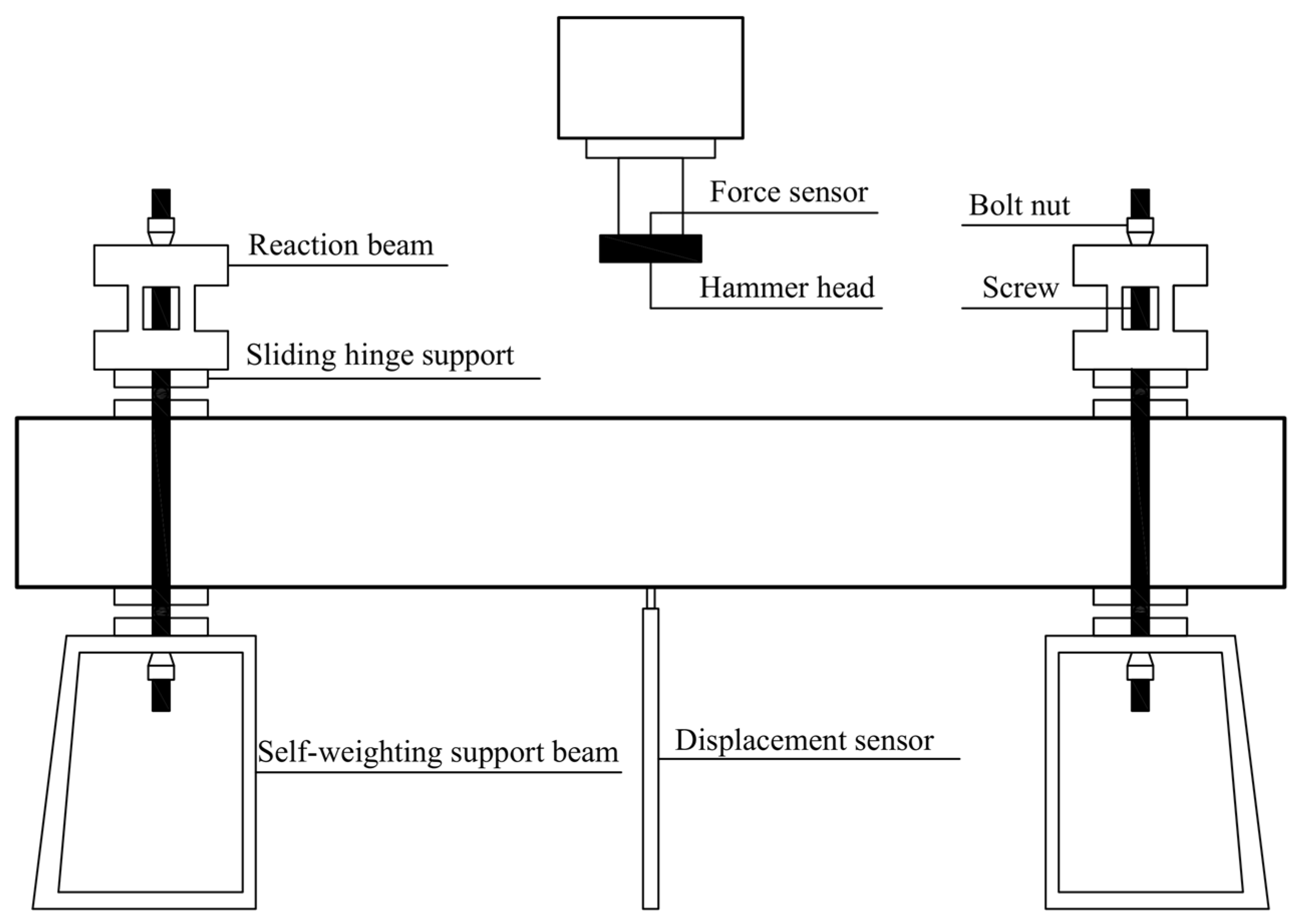
The experimental setup is shown in Figure 4. A rod-type displacement sensor was used to collect midspan deflection. The force sensor on the upper part of the hammerhead was used to collect the strain signal generated by the impact. The data acquisition system of the testing machine consists of an infrared laser trigger and a grating plate on the upper part of the hammerhead. When the grating plate passes through the infrared probe, it causes a change in the reflection signal, triggering a high-speed camera to capture the testing process and simultaneously triggering the data acquisition system to record the strain signal generated by the impact. The high-speed camera and infrared trigger device are shown in Figure 5.

4. Experimental Results and Discussion

4.1. Experimental Phenomenon

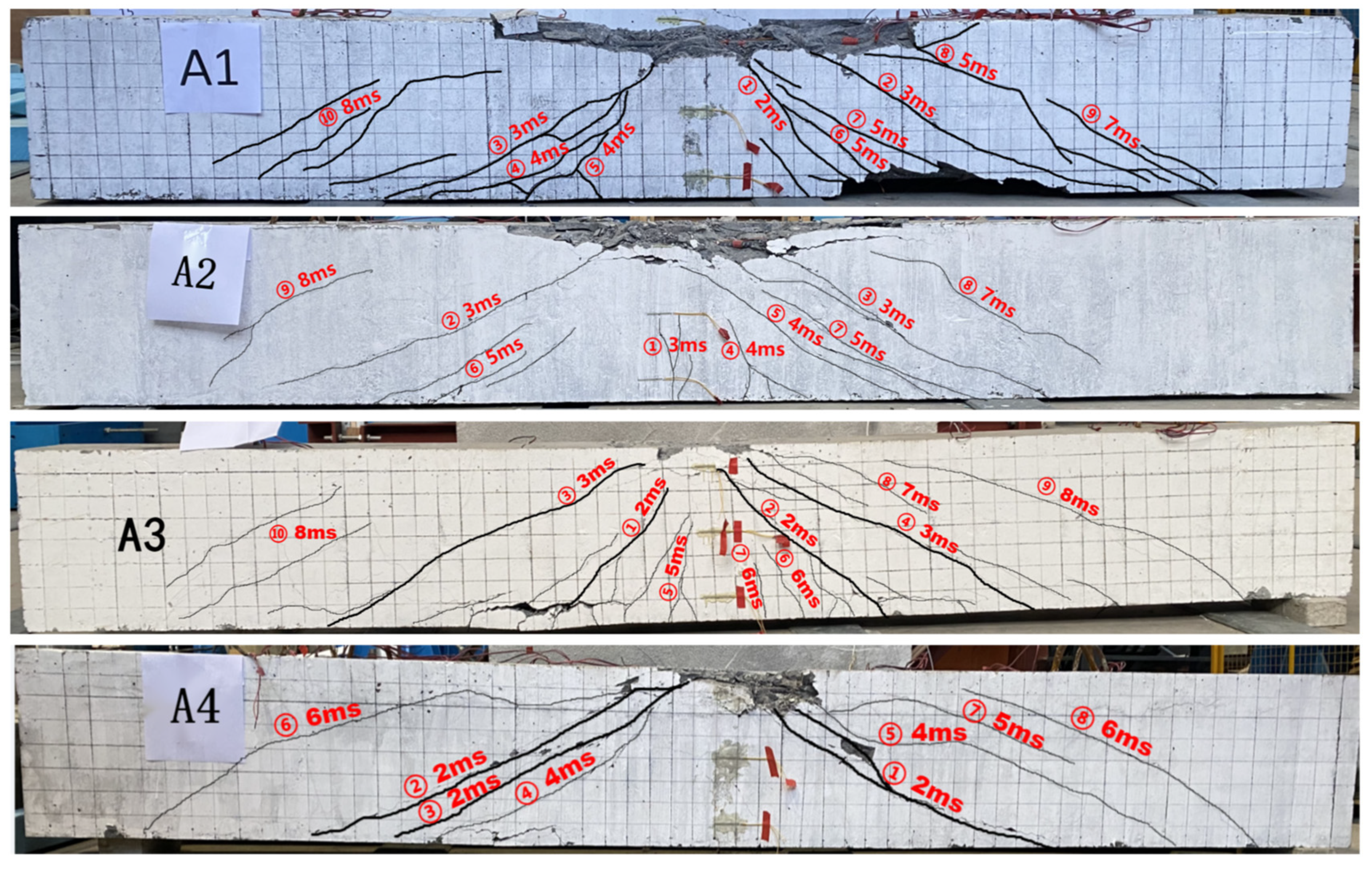
Figure 6 shows each specimen’s final crack and damage phenomenon, and Figure 7 shows the specimen’s crack and damage development process captured by the high-speed camera.
Specimen A1 is an unadulterated steel fiber test beam. Finally, the concrete of the protection layer in the compression zone at the top of the beam is completely crushed and spalled on the impact hammer body and the surrounding area. The upper longitudinal reinforcement is exposed, with a more damaged area and a flat damaged surface. As shown in Figure 7a, at 3 ms, extensive spalling occurred in the local concrete near the right support at the bottom of the beam where the oblique crack penetrated. The beam’s damage under the impact is concentrated on both sides of the impact area in the span, and the damage characteristics are shown as shear damage and local punching damage in the impact area in the span.
Specimen A2 was a 1% flat steel fiber-doped test beam. After the test, the specimen was observed and it was found that the angle of oblique cracks were mostly 60°. Vertical crack No.1 in the middle of the beam was extended by the cracking at the bottom of the beam, and the cracks were mainly fine shear oblique cracks without critical cracks. The concrete in the impact area was crushed off in a large area, and the longitudinal reinforcement was exposed. The concrete at the bottom of the beam was spalled off in a small amount by the impact, the lower longitudinal reinforcement was not exposed, and the beam as a whole was shear damaged.
Specimen A3 is a test beam with 1% wave-type steel fiber. The number of cracks in Specimen A3 is large, except for the cracks marked as No. 1~4 with a large width. The rest of the cracks are fine cracks. The cracks are radially concentrated in the middle of cracks No. 3 and No. 4, and the damage is characterized by shear damage and local punching damage in the impact area in the span.
Specimen A4 is a test beam with 0.5% flat- and 0.5% wave-type steel fibers. Figure 6 shows that a significant crack of comparable width was formed on the left and right sides of the span of the specimen. The final main cracks are radially distributed on both sides of the impact zone in the span, and arch-like shear diagonal cracks developed toward the impact load action point at the supports at both ends. The top impact area of the beam is broken and spalled in a small area, and the overall integrity of the beam is good. The local damage degree of the impact area in the span of the specimen is improved, and the damage mode is shear damage.

4.2. Analysis of Damage Pattern

According to the high-speed camera’s images, each specimen’s damage characteristics after impact are similar. At the beginning of the test, the test beam is subjected to the impact load, and the specimen is in the local response stage at the moment of hammer contact. The impact force rapidly reaches the peak, and the local area in the span of the beam is subjected to shear force and produces oblique cracks, at which time the span almost does not produce downward displacement. Subsequently, the stress wave generated by the impact load is transmitted to the supports at both ends. The beam specimen enters the overall response phase, the peak impact force drops to the bottom, the impact kinetic energy is transformed into deformation energy, the deflection in the span reaches the peak, and the pre-formed crack develops rapidly and its width increases and extends in the direction of the impact point.
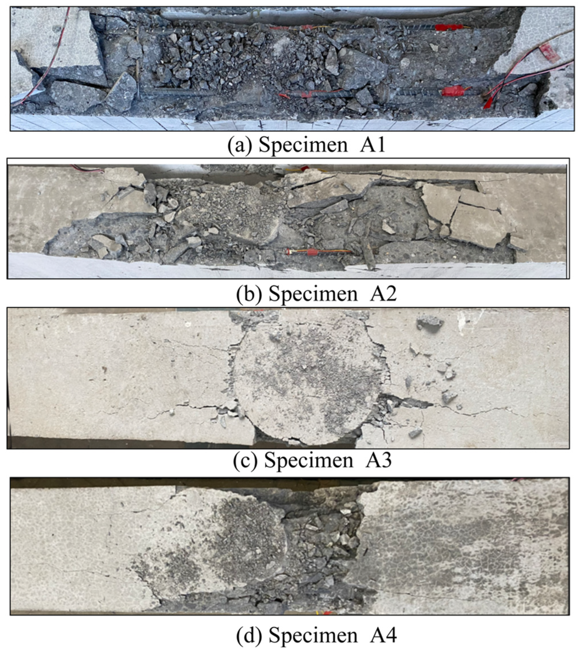
The stress wave generated by the impact produces an extremely high-stress concentration inside the concrete in the impact zone. During this process, the bonding force between the concrete aggregate and cementitious binder is destroyed under extremely high stress, resulting in aggregate cracking or detachment. As shown in Figure 8, under the impact load the protective layer around the beam’s top impact zone and the surrounding concrete suffers damage and spalling. In contrast, the area of damage and spalling in the test beam containing steel fibers is significantly reduced. This indicates that the steel fibers play a role in connecting and winding between the concrete matrix and bar reinforcement, enhancing the bonding force between them, reducing the weak interface of the test specimen, and maintaining its integrity after impact loading, thus significantly improving the brittle failure characteristics. Specifically, in Test Specimen A1 large areas of the surrounding concrete suffer damage and spalling, which is improved in Test Specimens A2 and A3 where the top concrete hardly suffered any damage. Only slight spalling was observed in the impact area of Test Specimen A4. The experimental results show that wavy steel fibers significantly contribute to improving the damage and spalling of concrete in the impact zone under mixed conditions. Wavy steel fibers can effectively improve the degree of spalling in the concrete of all-lightweight concrete beams in the impact zone, maintaining the structural integrity after impact.
Before the initiation of cracks in the test specimen, the mechanical interlocking and bonding between the steel fibers and concrete matrix can effectively improve the compressive and flexural failure modes of the concrete matrix. After the test specimen cracks, steel fibers bridging across the cracks play a ‘bridging’ role by consuming stresses through forms such as pull-out, deformation, fracture, and offset, which improves the impact toughness of the component, prevents and suppresses the initiation and development of cracks, and thus impacts the final crack morphology [33,35]. In the absence of steel fibers in the test specimen, wide macroscopic shear cracks may occur in the impact zone at the midspan, causing significant deterioration of the working performance and obvious localization characteristics. After incorporating steel fibers, cracks in the local impact zone of the test specimen have smaller widths, especially in single-dose, straight steel fiber specimens, and the number of cracks is significantly reduced in mixed steel fiber specimens.
In summary, randomly distributed steel fibers in concrete can change the direction of stress transmission, allowing the test specimen to transition from localized stress to overall stress quickly, improving stress concentration phenomena, suppressing unstable crack propagation, and blocking the initiation of macroscopic cracks. This allows the test specimen to consume more energy and enhance its impact toughness. After the test specimen is added with steel fibers, the crack distribution becomes more uniform and the beam is more likely to participate in response to impact, improving the degree of local damage in the midspan impact zone and allowing the specimen to retain more bearing capacity, thereby continuing to work with cracks under impact loads.

4.3. Time Course Analysis of Impact Force

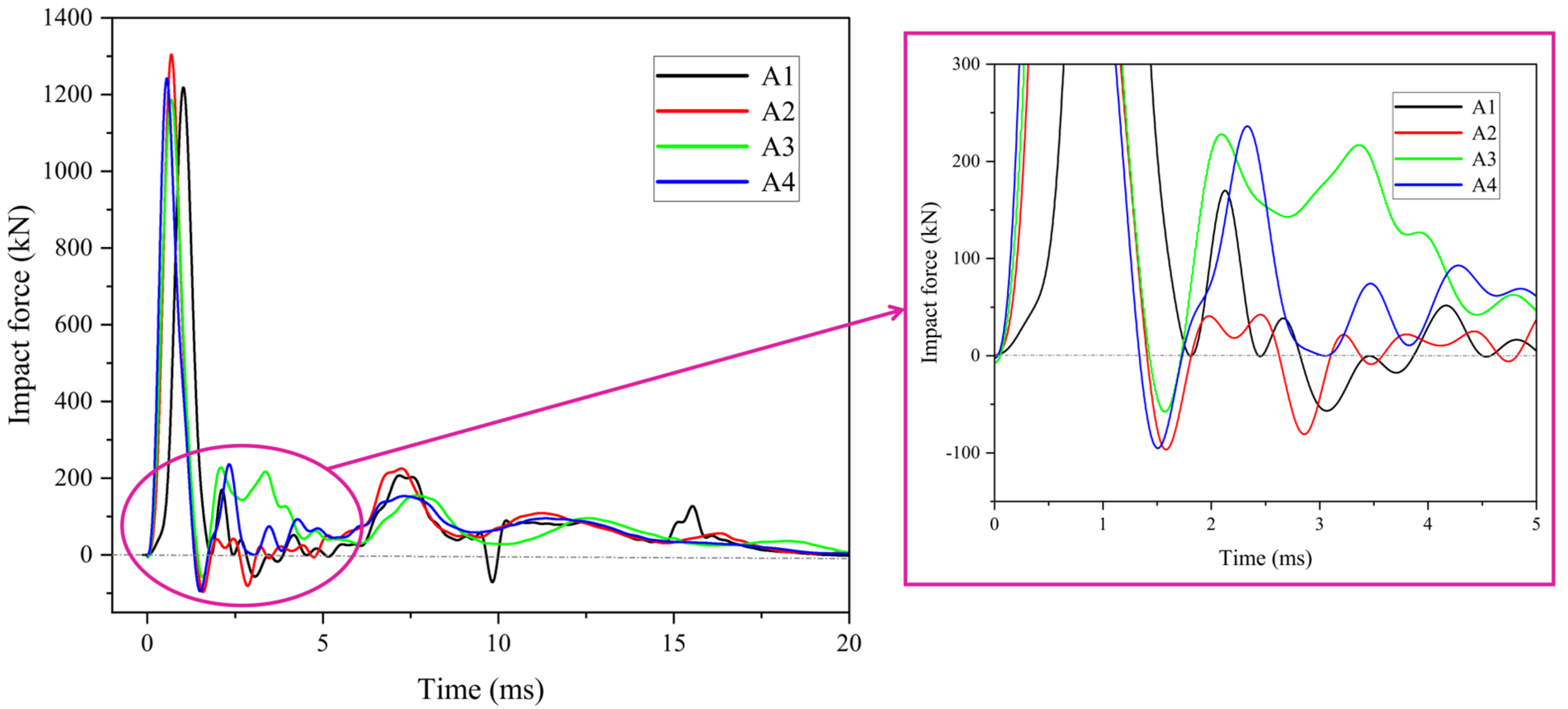
The impact force time-history curves for the beams under impact loading are given in Figure 9; the corresponding impact force characteristic values are listed in Table 5. Figure 9 shows that the compositions of the four beams are characterized by two larger amplitude oscillations and several smaller oscillations, a composition characteristic similar to the results of the published literature [11,12,13,18,36,37,38,39,40].
Analysis of the data in Table 5 reveals that Specimen A2 has the highest peak impact load, which is 6.98% higher than that of Specimen A1. Specimen A4 had a 1.89% higher peak impact force than A1, and Specimen A3 had a 2.62% lower peak impact force than A1. This means that the flat steel fiber significantly affects the specimens’ peak impact forces. It is worth noting that Specimen A3 has a significantly higher curve fluctuation range after the first peak load than the other specimens, A4 has a higher curve fluctuation range after the first peak load than A1 and A2, and A3 and A4 have a much higher second peak loads than the other specimens, which indicates that Specimens A3 and A4 still have a high stiffness after the first impact; Specimen A1 had issued local impact damage, the stiffness was much reduced, and no rebound occurred.
Within the design parameters of this test, the enhancement of the stiffness of Specimens A2 and A4 by steel fibers is the main reason for deciding that the peak impact force of Specimen A1 is smaller than the first two, which is consistent with the conclusion of the literature [16]. The lower peak impact force of Specimen A3 may be due to less distribution of steel fibers in the impact zone. However, it retains the most stiffness after being subjected to impact loading. The better integrity of the A3 beam body after being subjected to impact loading indicates that the wave-shaped steel fibers can effectively mitigate the internal and external damage of the all-lightweight concrete beam after impact.

4.4. Time History Analysis of Midspan Displacement

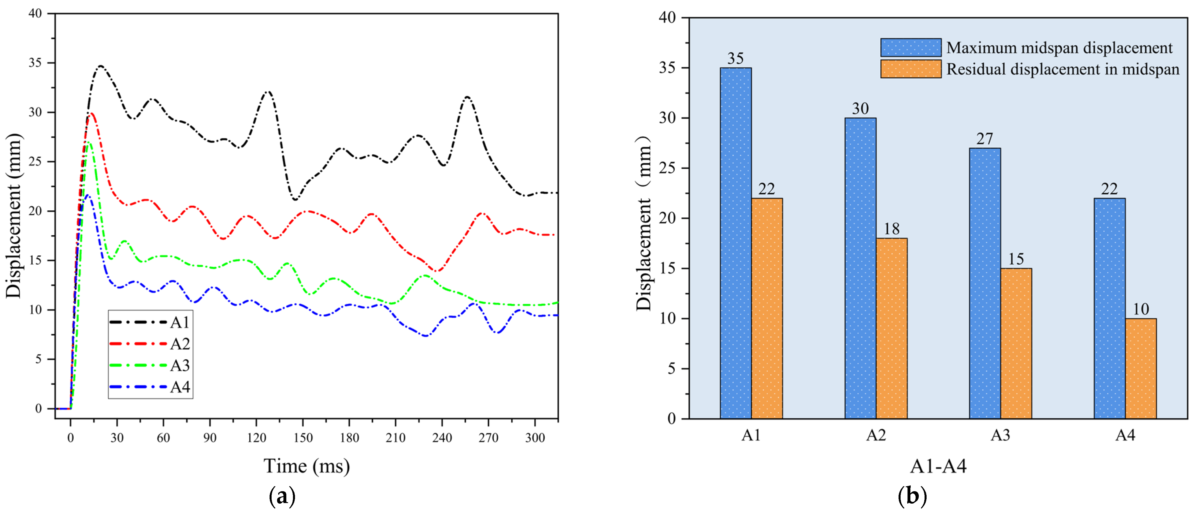
As shown in Figure 10, except for Specimen A1, Specimens A2, A3, and A4 have the same span displacement time curve, which roughly goes through two stages: First, the peak stage, where, after the contact between the falling hammer and the beam, the impact energy is transformed to the deformation energy, the test beam span develops to the maximum value rapidly within 10–20 ms, and then the beam body springs back upward and the displacement peak falls back rapidly. Second, the hammerhead repeatedly impacts the beam when falling and rebounding in the oscillation stage. The stress wave generated by the impact makes the curve fluctuate in a sine wave pattern. The displacement in the span slowly decreases and gradually stabilizes in a particular range.
As shown in Figure 10, Specimens A1, A2, A3, and A4 climbed to the second displacement peak after rising to the maximum displacement in the span and falling by 5 mm, 9 mm, 12 mm, and 9 mm, respectively, and the ratio of the second displacement peak to the maximum displacement peak was 0.89, 0.70, 0.63 and 0.59 for Specimens A1, A2, A3, and A4, respectively. During the period of 0.04–0.3 s, Specimen A1 experienced several undulating peaks, 0.04–0.3 s, while the peaks of Specimens A2, A3, and A4 were less undulating. The above data reflect that the steel fiber-doped specimens’ deformation process can reduce the specimens’ deformation amplitudes, reduce the internal damage of the specimens during the deformation process, and improve the durability of the specimens.
Figure 11 shows the maximum and residual displacement of Specimens A1-A4 in the span. Compared with Specimen A1, the maximum midspan displacements of Specimens A2, A3, and A4 are reduced by 14.29%, 22.86%, and 37.14%, respectively, and the residual displacements are reduced by 18.18%, 50.91%, and 54.55%, respectively, which indicates that the impact displacement magnitude of all-light concrete beams can be improved by mixing wave-shaped steel fibers alone than flat steel fibers. The improvement of the toughness of all-light concrete beams is better when mixing two shapes of steel fibers. This indicates that the impact displacement magnitudes of all-lightweight concrete beams are improved more by mixing both shapes of steel fibers than by flat steel fibers. As seen in Figure 11, the impact loads of Specimens A2, A3, and A4 peaked when the spanwise displacement of the four beams reached 3.5 mm. In contrast, the impact load of Specimen A1 is smaller at this time, indicating that the steel fiber-doped specimens can absorb more energy in the same displacement deformation so that the specimens retain more stiffness after the first impact, which is consistent with the findings in the impact time course analysis.

5. Conclusions

This study determined the mechanical property enhancement of steel fibers on all-lightweight concrete in material property tests. Based on the impact tests, four all-lightweight concrete beams were designed to investigate the effect of flat and wavy steel fibers on the impact resistance of all-lightweight concrete beams with single and mixed admixtures. The following conclusions were drawn from this study:
(1)
The incorporation of steel fibers can improve the mechanical properties of all-lightweight concrete. The flexural strength can be increased by up to 52.83%, and the splitting tensile strength can be increased by 65.52%.
(2)
Waveform steel fibers improve the splitting tensile properties better than flat rows, and the best mechanical properties of the material are achieved when two shapes of steel fibers are mixed.
(3)
Incorporating steel fibers in all-lightweight concrete beams can reduce the local damage of beams under impact loading and stall the generation of macroscopic cracks.
(4)
Flat steel fibers have the most prominent effect on the peak impact force enhancement of all-lightweight concrete beams, which is 6.98% higher than all-lightweight concrete beams without steel fibers.
(5)
The use of flat and straight steel fibers alone, wave-type steel fibers alone, mixed flat and straight steel fibers, and wave-type steel fibers resulted in a 14.29%, 22.86%, 37.14%, and 18.18%, 50.91%, and 54.55% reduction in peak midspan displacement and residual displacement, respectively, for all-lightweight concrete beams. The peak span-to-span displacement and residual displacement of all-light concrete beams under the steel fiber mixing condition are the smallest, showing a positive mixing effect.
(6)
Steel fibers can effectively alleviate the vibration amplitude of all-lightweight concrete beams after impact loading, reduce the internal damage of beams, and improve the impact toughness of beams. The specimens mixed with steel fibers have the smallest fluctuation of the displacement curve and the smallest weakening of specimen stiffness.

Author Contributions

Conceptualization, X.W.; methodology, X.W.; software, X.W. and W.C.; validation, X.W. and W.C.; formal analysis, X.W., Q.W. and W.C.; investigation, X.W.; resources, X.W.; data curation, W.C.; writing—original draft preparation, Q.W. and X.W.; writing—review and editing, X.W. and Q.W.; visualization, Q.W.; supervision, X.W.; project administration, X.W.; All authors have read and agreed to the published version of the manuscript.

Funding

This research was funded by [Key R & D Project of Jilin Provincial Science and Technology Department] grant number [20210203145SF] and the APC was funded by [W.X.].

Data Availability Statement

Not applicable.

Conflicts of Interest

The authors declare no conflict of interest.

References

  1. Bindiganavile, V.; Banthia, N. Size Effects and the Dynamic Response of Plain Concrete. J. Mater. Civ. Eng. 2006, 18, 485–491. [Google Scholar] [CrossRef]
  2. Yoo, D.-Y.; Banthia, N. Impact Resistance of Fiber-Reinforced Concrete—A Review. Cem. Concr. Compos. 2019, 104, 103389. [Google Scholar] [CrossRef]
  3. Ožbolt, J.; Sharma, A.; Reinhardt, H.-W. Dynamic Fracture of Concrete—Compact Tension Specimen. Int. J. Solids Struct. 2011, 48, 1534–1543. [Google Scholar] [CrossRef]
  4. Klepaczko, J.R. On a Very High Rate Sensitivity of Concrete Failure at High Loading Rates and Impact. In Brittle Matrix Composites 7; Elsevier: Amsterdam, The Netherlands, 2003; pp. 1–27. ISBN 978-1-85573-769-3. [Google Scholar]
  5. Fujikake, K.; Senga, T.; Ueda, N.; Ohno, T.; Katagiri, M. Effects of Strain Rate on Tensile Behavior of Reactive Powder Concrete. J. Adv. Concr. Technol. 2006, 4, 79–84. [Google Scholar] [CrossRef]
  6. Cusatis, G. Strain-Rate Effects on Concrete Behavior. Int. J. Impact Eng. 2011, 38, 162–170. [Google Scholar] [CrossRef]
  7. Papadopoulos, N.A.; Naoum, M.C.; Sapidis, G.M.; Chalioris, C.E. Cracking and Fiber Debonding Identification of Concrete Deep Beams Reinforced with C-FRP Ropes against Shear Using a Real-Time Monitoring System. Polymers 2023, 15, 473. [Google Scholar] [CrossRef]
  8. Xiao, J.; Li, L.; Shen, L.; Poon, C.S. Compressive Behaviour of Recycled Aggregate Concrete under Impact Loading. Cem. Concr. Res. 2015, 71, 46–55. [Google Scholar] [CrossRef]
  9. Guo, Y.; Xie, J.; Zheng, W.; Li, J. Effects of Steel Slag as Fine Aggregate on Static and Impact Behaviours of Concrete. Constr. Build. Mater. 2018, 192, 194–201. [Google Scholar] [CrossRef]
  10. Lee, S.; Kim, C.; Yu, Y.; Cho, J.-Y. Effect of Reinforcing Steel on the Impact Resistance of Reinforced Concrete Panel Subjected to Hard-Projectile Impact. Int. J. Impact Eng. 2021, 148, 103762. [Google Scholar] [CrossRef]
  11. Jin, L.; Lan, Y.; Zhang, R.; Du, X. Impact Resistance of RC Beams under Different Combinations of Mass and Velocity: Mesoscale Numerical Analysis. Archiv. Civ. Mech. Eng. 2020, 20, 119. [Google Scholar] [CrossRef]
  12. Liao, W.; Li, M.; Zhang, W.; Tian, Z. Experimental Studies and Numerical Simulation of Behavior of RC Beams Retrofitted with HSSWM-HPM under Impact Loading. Eng. Struct. 2017, 149, 131–146. [Google Scholar] [CrossRef]
  13. Zhou, D.; Li, R.; Wang, J.; Guo, C. Study on Impact Behavior and Impact Force of Bridge Pier Subjected to Vehicle Collision. Shock Vib. 2017, 2017, 1–12. [Google Scholar] [CrossRef]
  14. Saatci, S.; Vecchio, F.J. Effects of Shear Mechanisms on Impact Behavior of Reinforced Concrete Beams. ACI Struct. J. 2009, 106, 78–86. [Google Scholar] [CrossRef]
  15. Zhao, D.-B.; Yi, W.-J.; Kunnath, S.K. Shear Mechanisms in Reinforced Concrete Beams under Impact Loading. J. Struct. Eng. 2017, 143, 04017089. [Google Scholar] [CrossRef]
  16. Li, H.; Chen, W.; Pham, T.M.; Hao, H. Analytical and Numerical Studies on Impact Force Profile of RC Beam under Drop Weight Impact. Int. J. Impact Eng. 2021, 147, 103743. [Google Scholar] [CrossRef]
  17. Fujikake, K.; Senga, T.; Ueda, N.; Ohno, T.; Katagiri, M. Study on Impact Response of Reactive Powder Concrete Beam and Its Analytical Model. J. Adv. Concr. Technol. 2006, 4, 99–108. [Google Scholar] [CrossRef]
  18. Goldston, M.; Remennikov, A.; Sheikh, M.N. Experimental Investigation of the Behaviour of Concrete Beams Reinforced with GFRP Bars under Static and Impact Loading. Eng. Struct. 2016, 113, 220–232. [Google Scholar] [CrossRef]
  19. Merwad, A.M.; El-Sisi, A.A.; Mustafa, S.A.A.; Sallam, H.E.-D.M. Lateral Impact Response of Rubberized-Fibrous Concrete-Filled Steel Tubular Columns: Experiment and Numerical Study. Buildings 2022, 12, 1566. [Google Scholar] [CrossRef]
  20. Jackowski, M.; Malek, M. A Multi-Site Study of a New Cement Composite Brick with Partial Cement Substitutes and Waste Materials. Case Stud. Constr. Mater. 2023, 18, e01992. [Google Scholar] [CrossRef]
  21. Tayeh, B.; Hadzima-Nyarko, M.; Riad, M.Y.R.; Hafez, R.D.A. Behavior of Ultra-High-Performance Concrete with Hybrid Synthetic Fiber Waste Exposed to Elevated Temperatures. Buildings 2023, 13, 129. [Google Scholar] [CrossRef]
  22. Lusis, V.; Annamaneni, K.K.; Krasnikovs, A. Concrete Reinforced by Hybrid Mix of Short Fibers under Bending. Fibers 2022, 10, 11. [Google Scholar] [CrossRef]
  23. Kadela, M.; Małek, M.; Jackowski, M.; Kunikowski, M.; Klimek, A.; Dudek, D.; Rośkowicz, M. Recycling of Tire-Derived Fiber: The Contribution of Steel Cord on the Properties of Lightweight Concrete Based on Perlite Aggregate. Materials 2023, 16, 2124. [Google Scholar] [CrossRef]
  24. Trabucchi, I.; Tiberti, G.; Conforti, A.; Medeghini, F.; Plizzari, G.A. Experimental Study on Steel Fiber Reinforced Concrete and Reinforced Concrete Elements under Concentrated Loads. Constr. Build. Mater. 2021, 307, 124834. [Google Scholar] [CrossRef]
  25. Sevil, T.; Baran, M.; Bilir, T.; Canbay, E. Use of Steel Fiber Reinforced Mortar for Seismic Strengthening. Constr. Build. Mater. 2011, 25, 892–899. [Google Scholar] [CrossRef]
  26. Dabbaghi, F.; Dehestani, M.; Yousefpour, H. Residual Mechanical Properties of Concrete Containing Lightweight Expanded Clay Aggregate (LECA) after Exposure to Elevated Temperatures. Struct. Concr. 2022, 23, 2162–2184. [Google Scholar] [CrossRef]
  27. Shafigh, P.; Nomeli, M.A.; Alengaram, U.J.; Mahmud, H.B.; Jumaat, M.Z. Engineering Properties of Lightweight Aggregate Concrete Containing Limestone Powder and High Volume Fly Ash. J. Clean. Prod. 2016, 135, 148–157. [Google Scholar] [CrossRef]
  28. Ahn, Y.B.; Jang, J.G.; Lee, H.K. Mechanical Properties of Lightweight Concrete Made with Coal Ashes after Exposure to Elevated Temperatures. Cem. Concr. Compos. 2016, 72, 27–38. [Google Scholar] [CrossRef]
  29. Chung, S.-Y.; Elrahman, M.A.; Stephan, D.; Kamm, P.H. The Influence of Different Concrete Additions on the Properties of Lightweight Concrete Evaluated Using Experimental and Numerical Approaches. Constr. Build. Mater. 2018, 189, 314–322. [Google Scholar] [CrossRef]
  30. JGJ/T12-2010; Technical Specification for Application of Fiber Reinforced Concrete. Standards Press of China: Beijing, China, 2010.
  31. JGJ/T12-2019; Technical Standard for Application of Lightweight Aggregate Concrete. Standards Press of China: Beijing, China, 2019.
  32. GB/T 39147-2020; Steel Fiber for Concrete. National Standardization Management Committee: Beijing, China, 2020.
  33. Islam, A.; Alengaram, U.J.; Jumaat, M.Z.; Ghazali, N.B.; Yusoff, S.; Bashar, I.I. Influence of Steel Fibers on the Mechanical Properties and Impact Resistance of Lightweight Geopolymer Concrete. Constr. Build. Mater. 2017, 152, 964–977. [Google Scholar] [CrossRef]
  34. Thomoglou, A.K.; Falara, M.G.; Gkountakou, F.I.; Elenas, A.; Chalioris, C.E. Smart Cementitious Sensors with Nano-, Micro-, and Hybrid-Modified Reinforcement: Mechanical and Electrical Properties. Sensors 2023, 23, 2405. [Google Scholar] [CrossRef]
  35. Kytinou, V.K.; Chalioris, C.E.; Karayannis, C.G.; Elenas, A. Effect of Steel Fibers on the Hysteretic Performance of Concrete Beams with Steel Reinforcement—Tests and Analysis. Materials 2020, 13, 2923. [Google Scholar] [CrossRef]
  36. Deng, Y.; Tuan, C.Y.; Xiao, Y. Flexural Behavior of Concrete-Filled Circular Steel Tubes under High-Strain Rate Impact Loading. J. Struct. Eng. 2012, 138, 449–456. [Google Scholar] [CrossRef]
  37. Alam, M.I.; Fawzia, S.; Zhao, X.-L.; Remennikov, A.M.; Bambach, M.R.; Elchalakani, M. Performance and Dynamic Behaviour of FRP Strengthened CFST Members Subjected to Lateral Impact. Eng. Struct. 2017, 147, 160–176. [Google Scholar] [CrossRef]
  38. Fan, W.; Shen, D.; Yang, T.; Shao, X. Experimental and Numerical Study on Low-Velocity Lateral Impact Behaviors of RC, UHPFRC and UHPFRC-Strengthened Columns. Eng. Struct. 2019, 191, 509–525. [Google Scholar] [CrossRef]
  39. Han, L.-H.; Hou, C.-C.; Zhao, X.-L.; Rasmussen, K.J.R. Behaviour of High-Strength Concrete Filled Steel Tubes under Transverse Impact Loading. J. Constr. Steel Res. 2014, 92, 25–39. [Google Scholar] [CrossRef]
  40. Jiang, H.; Wang, X.; He, S. Numerical Simulation of Impact Tests on Reinforced Concrete Beams. Mater. Des. 2012, 39, 111–120. [Google Scholar] [CrossRef]
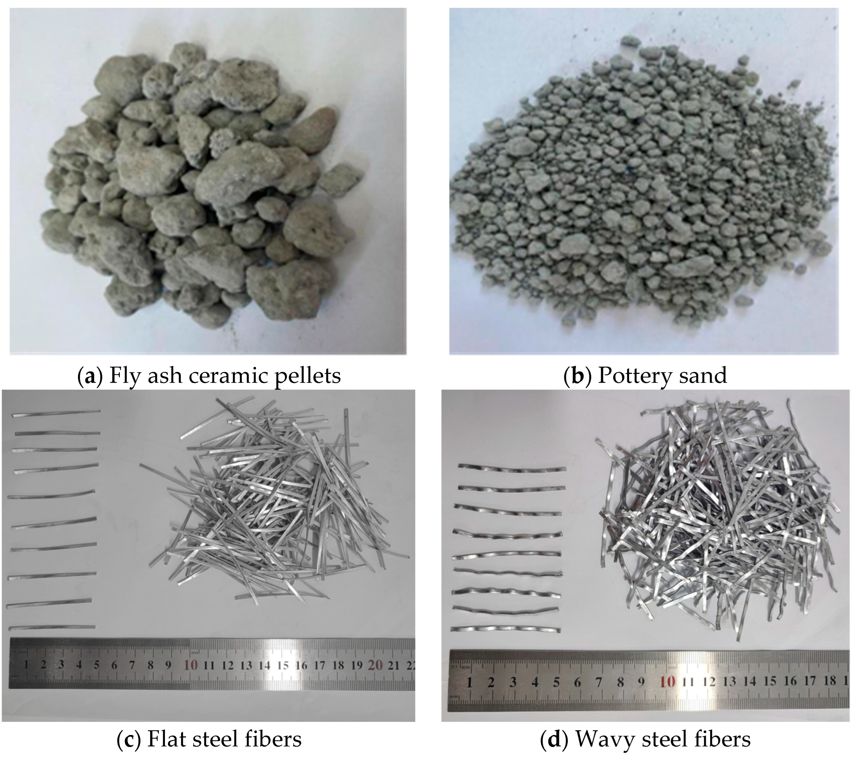
Figure 1. All-lightweight concrete composition materials.
Buildings 13 01251 g001
Figure 2. All-lightweight concrete beams details.
Buildings 13 01251 g002
Figure 3. Drop hammer tester.
Buildings 13 01251 g003
Figure 4. Experimental devices.
Buildings 13 01251 g004
Figure 5. Information collection equipment: (a) High-speed camera; (b) Infrared trigger device.
Buildings 13 01251 g005
Figure 6. Final crack and damage morphology of the specimens after the test.
Buildings 13 01251 g006
Figure 7. Specimens A1-A4 crack and damage development process.
Buildings 13 01251 g007
Figure 8. View of concrete damage in the impact area of the specimen.
Buildings 13 01251 g008
Figure 9. Impact force time history curve.
Buildings 13 01251 g009
Figure 10. Specimen midspan displacement details: (a) Midspan displacement time history curve; (b) Maximum midspan displacement and residual displacement.
Buildings 13 01251 g010
Figure 11. The displacement-impact curve of Specimen A1–A4.
Buildings 13 01251 g011
Table 1. Proportioning information of all-lightweight concrete mixtures.
Steel Fiber Volume Rate
(%)
Cement
(kg)
Fly Ash Ceramic Pellets (kg)Pottery Sand
(kg)
Fly Ash
(kg)
Water Reducing Admixture
(kg)
Water (kg)
-450693531503.6200
1440670558403.6192
Table 2. Steel fiber characteristics.
Type of Steel FiberThickness
(mm)
Width
(mm)
Length
(mm)
Equivalent L/D RatioTensile Strength
(MPa)
Flat1.02.05031.25≥700
Wavy1.02.05031.25≥700
Table 3. Strength test results for all-lightweight concrete.
Fiber Content(%)Cube Crushing Strength
(MPa)
Prism Compressive Strength
(MPa)
Break off Strength
(MPa)
Split Tensile Strength
(MPa)
Elastic Modulus
(MPa)
FlatWavy
--36.334.12.652.93.02 × 104
1-38.438.43.544.83.33 × 104
-142.038.94.043.93.33 × 104
0.50.542.139.64.054.73.43 × 104
Table 4. Design parameter information for all-lightweight concrete beams.
No. Steel Fiber Volume Rate
(%)
b × h
(mm)
Upper
Longitudinal Bar
Lower
Longitudinal Bar
StirrupsReinforcement Ratio
(%)
Stirrup Ratio
(%)
FlatWavy
A1--200 × 4002 C 163 C 20A8@2001.180.252
A21-
A3-1
A40.50.5
Table 5. Peak impact force values.
No. First Peak (KN)Duration of First Peak (ms)Second Peak (kN)
A112181.82170
A213031.5842
A311861.57228
A412411.49236
Disclaimer/Publisher’s Note: The statements, opinions and data contained in all publications are solely those of the individual author(s) and contributor(s) and not of MDPI and/or the editor(s). MDPI and/or the editor(s) disclaim responsibility for any injury to people or property resulting from any ideas, methods, instructions or products referred to in the content.