
Response Monitoring and Analysis in Deep Foundation Pit Excavation: A Case Study in Soft Soil at Subway Tunnel Intersections
 ,
,
Abstract
:1. Introduction
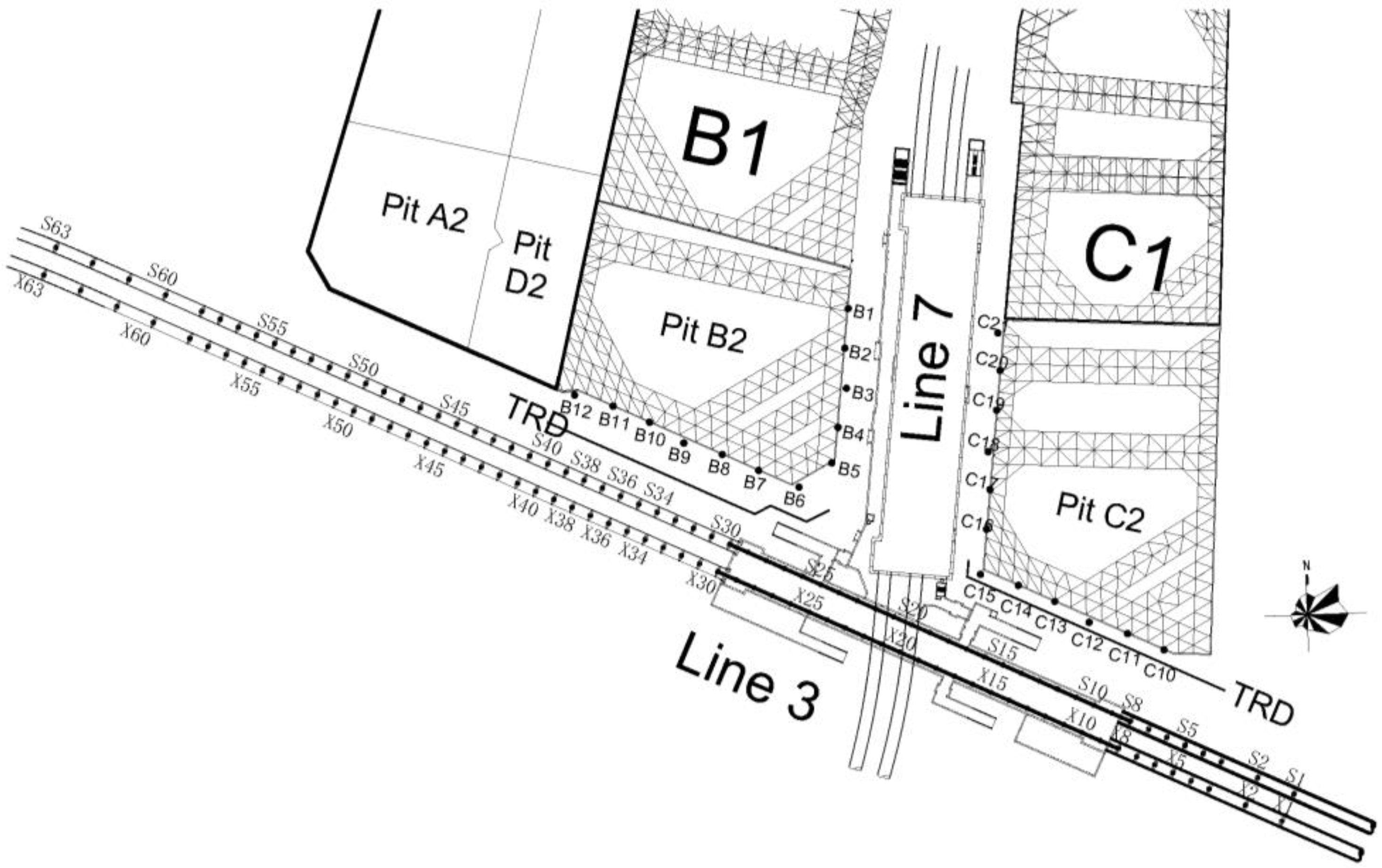
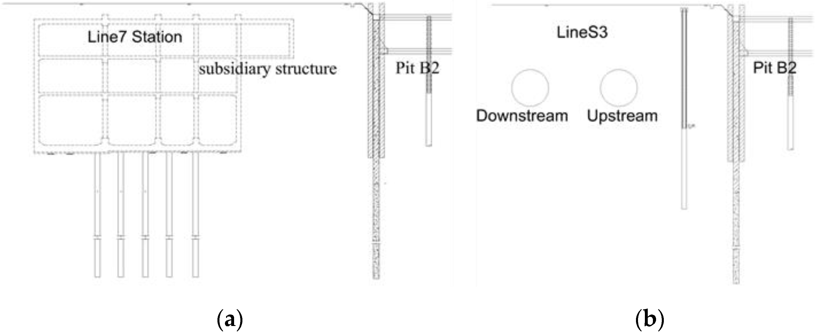
2. Project Overview
3. Measured Results of Foundation Pits and Subway Tunnel
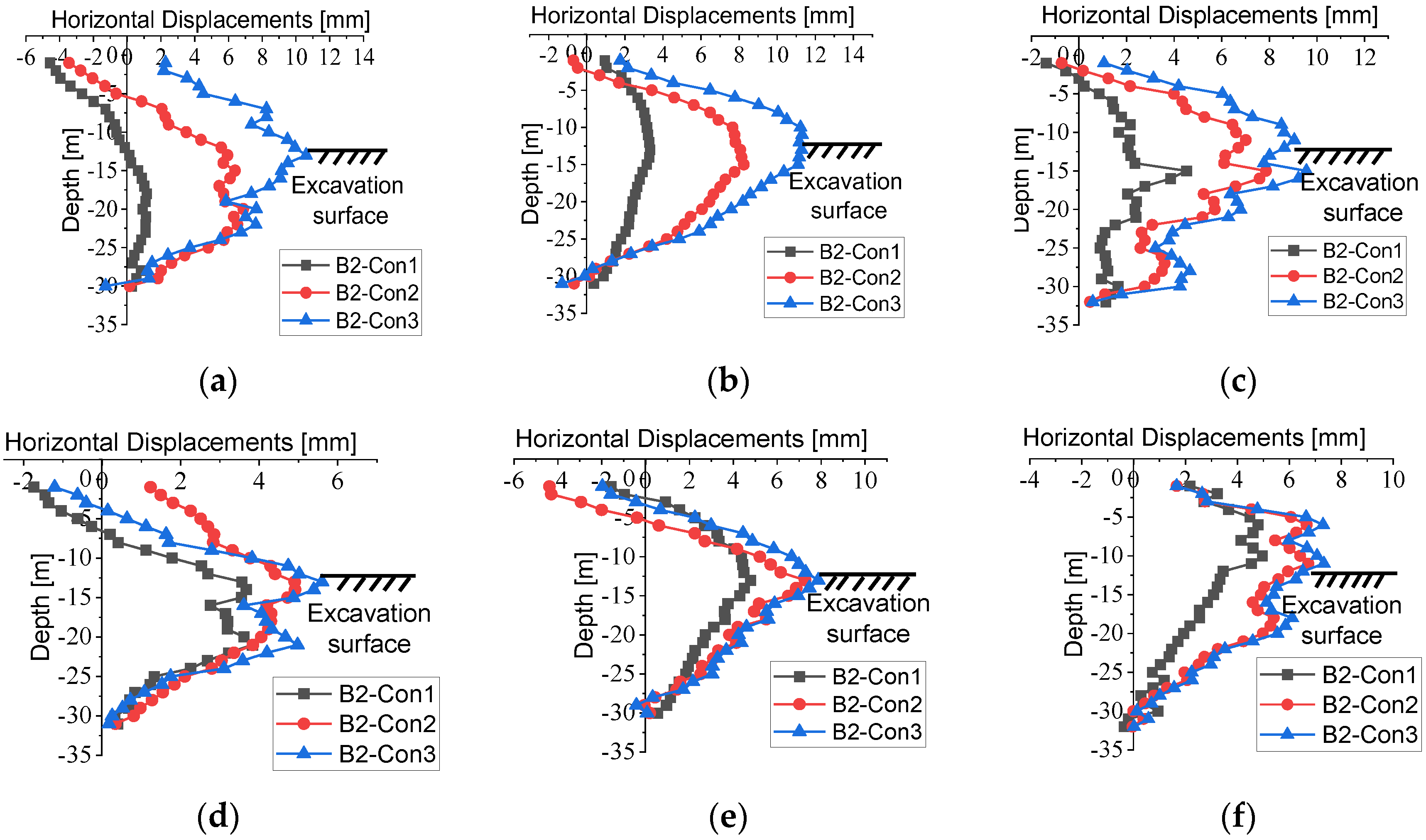
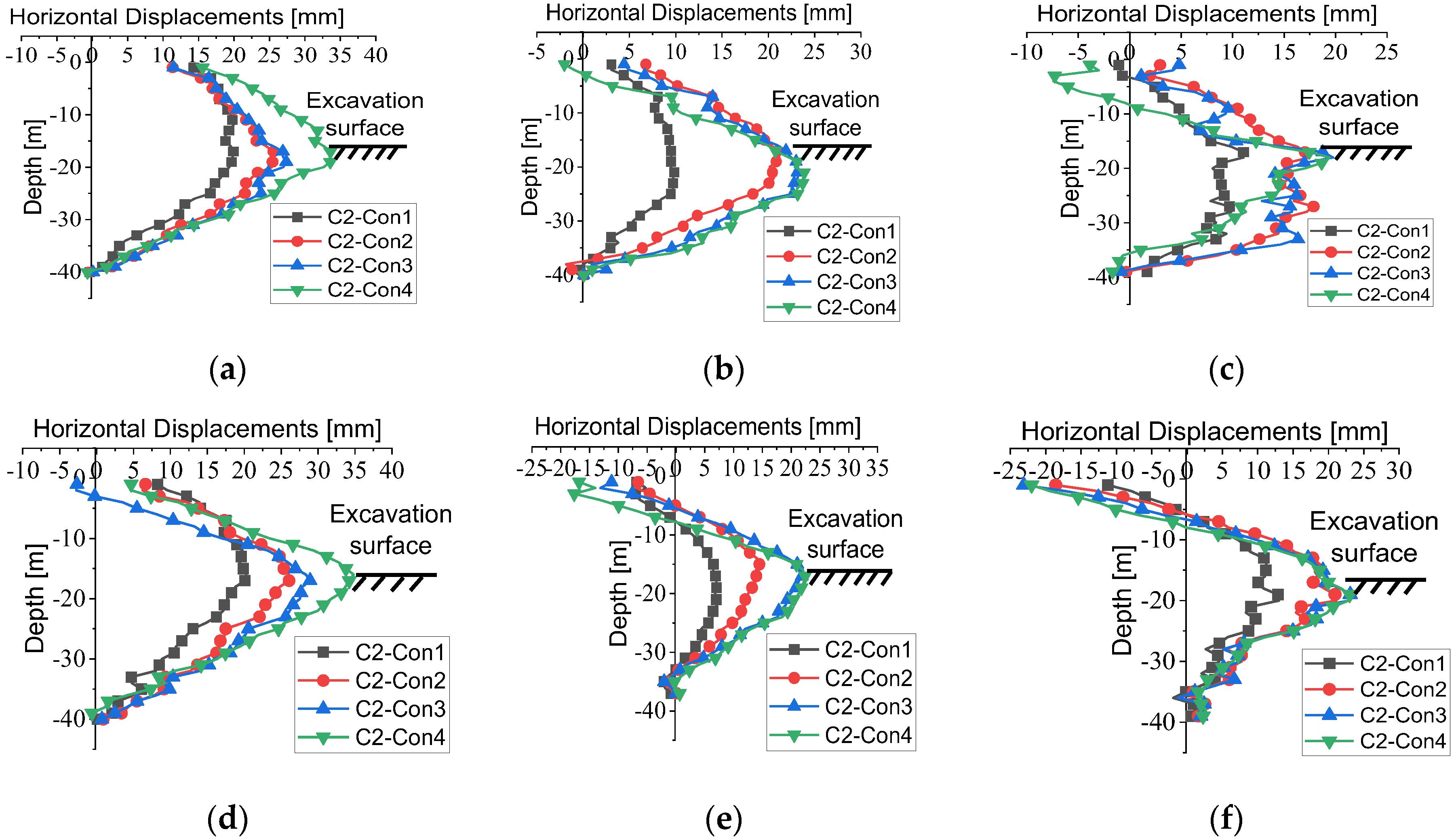
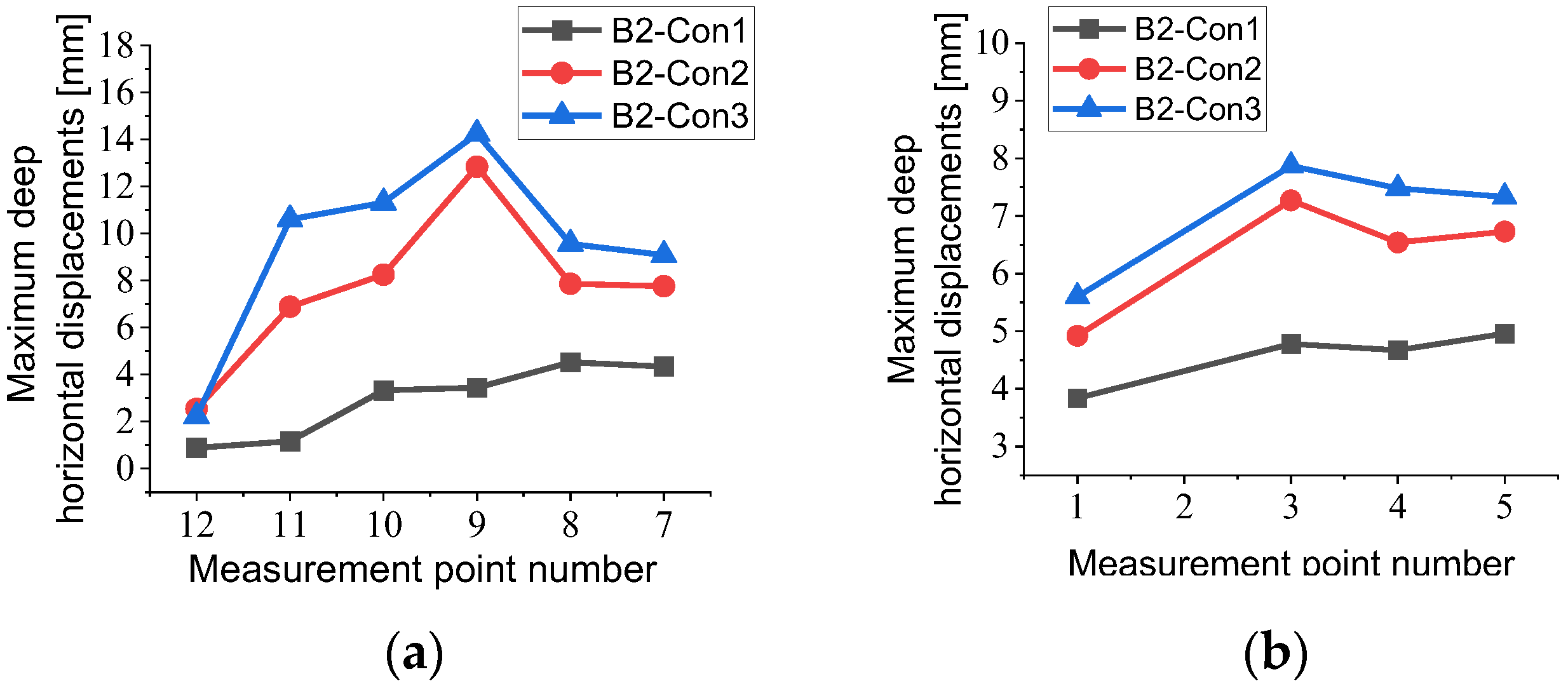
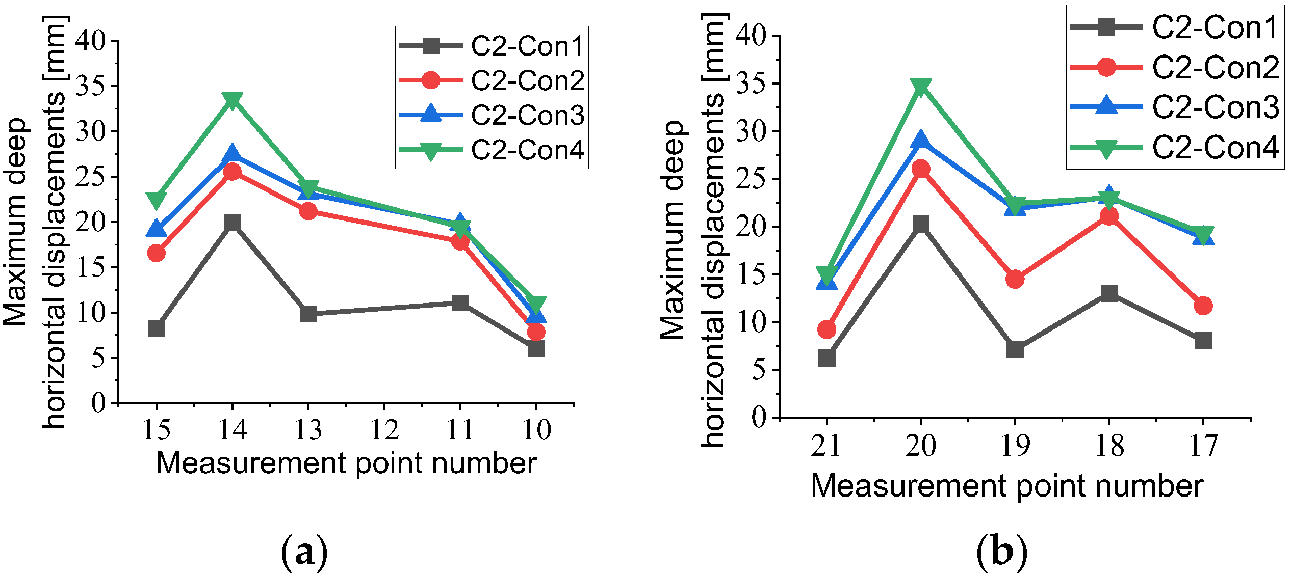
3.1. Displacements of Foundation Pits
3.2. Displacements of Subway Tunnel
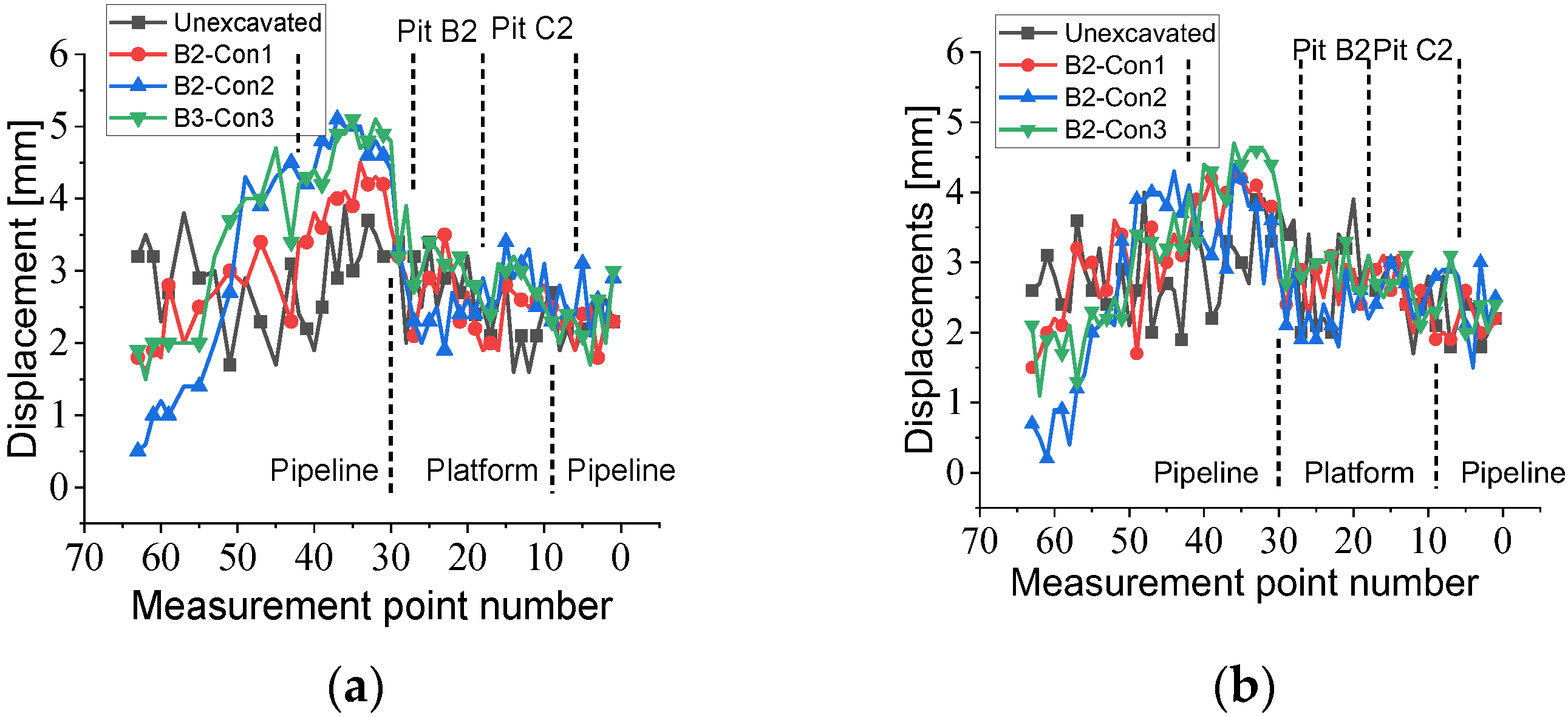
3.2.1. Horizontal and Vertical Displacements
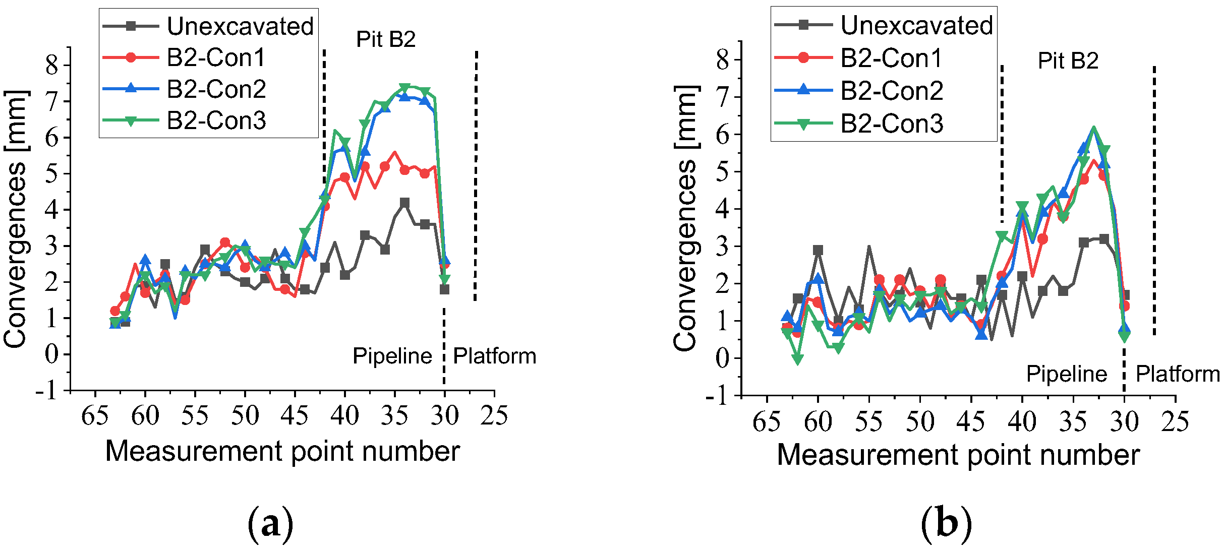
3.2.2. Horizontal and Vertical Convergences
4. Discussion
4.1. Displacement Relationship between the Tunnel and Foundation Pit
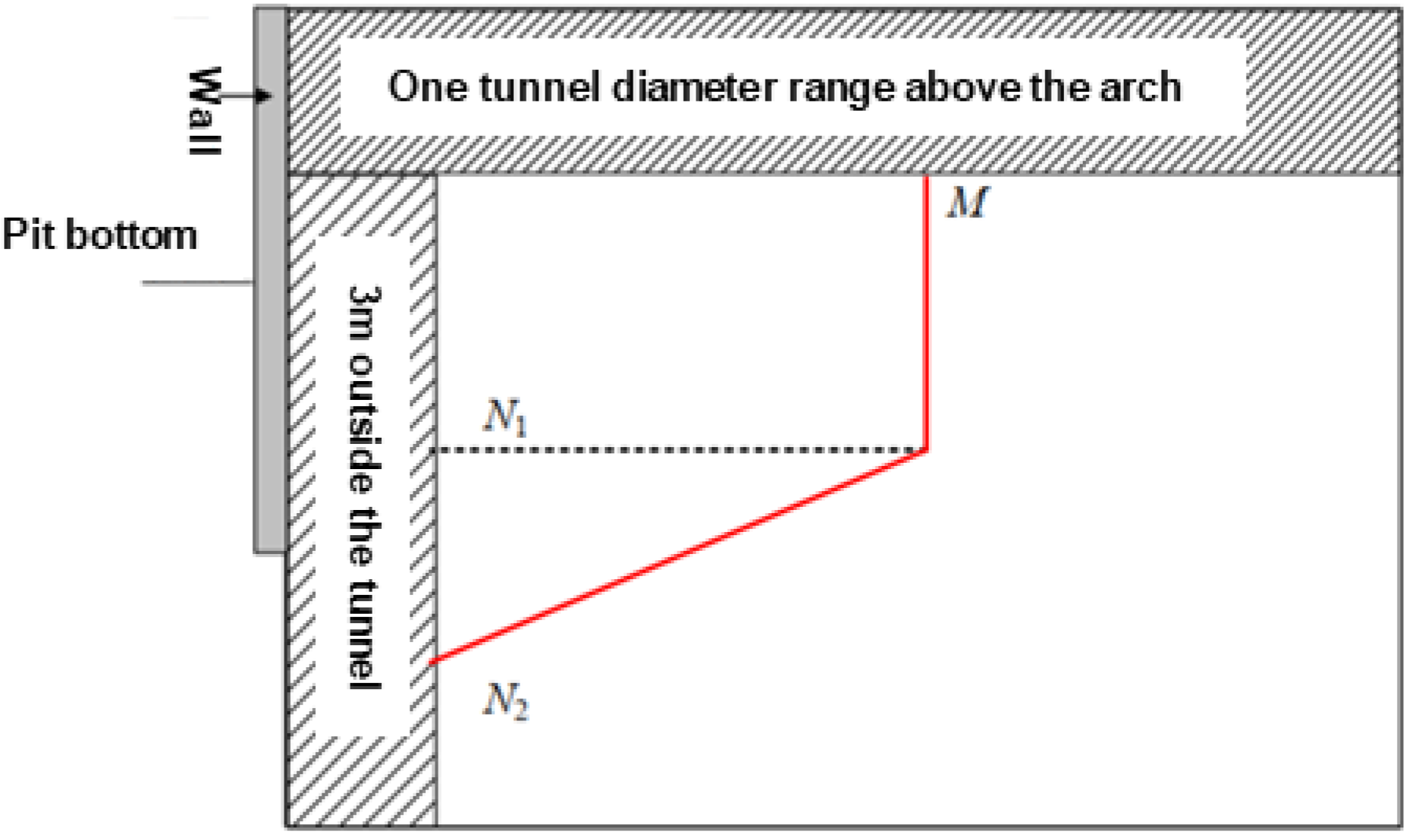
4.2. Influence Zone of Tunnel Displacement
5. Conclusions
Author Contributions
Funding
Data Availability Statement
Acknowledgments
Conflicts of Interest
References
- Ding, Z.; Jin, J.; Han, T.C. Analysis of the zoning excavation monitoring data of a narrow and deep foundation pit in a soft soil area. J. Geophys. Eng. 2018, 15, 1231–1241. [Google Scholar] [CrossRef]
- Yang, T.; Liu, S.; Wang, X.; Zhao, H.; Liu, Y.; Li, Y. Analysis of the deformation law of deep and large foundation pits in soft soil areas. Front. Earth Sci. 2022, 10, 9. [Google Scholar] [CrossRef]
- Chen, S.; Cui, J.; Liang, F. Case study on the deformation coupling effect of a deep foundation pit group in a coastal soft soil area. Appl. Sci. 2022, 12, 6205. [Google Scholar] [CrossRef]
- Zeng, F.Y.; Zhang, Z.J.; Wang, J.H.; Li, M.G. Observed performance of two adjacent and concurrently excavated deep foundation pits in soft clay. J. Perform. Constr. Facil. 2018, 32, 04018040. [Google Scholar] [CrossRef]
- Chen, X. Research on combined construction technology for cross-subway tunnels in underground spaces. Engineering 2018, 4, 103–111. [Google Scholar] [CrossRef]
- Vinoth, M.; MS, A. Behaviour of existing tunnel due to adjacent deep excavation-a review. Int. J. Geotech. Eng. 2022, 16, 1132–1151. [Google Scholar] [CrossRef]
- Meng, F.Y.; Chen, R.P.; Xu, Y.; Wu, K.; Wu, H.N.; Liu, Y. Contributions to responses of existing tunnel subjected to nearby excavation: A review. Tunn. Undergr. Space Technol. 2022, 119, 104195. [Google Scholar] [CrossRef]
- Liu, B.; Shao, C.; Xu, W. Influenced zone of deep excavation on adjacent tunnel displacement and control effect of ground improvement in soft soil. Appl. Sci. 2022, 12, 9047. [Google Scholar] [CrossRef]
- Liu, B.; Zhang, D.; Li, J. Prediction formula and its application of existing tunnel deformation induced by laterally adjacent deep excavation based on case statistics. Rock Soil Mech. 2022, 43, 501–512. [Google Scholar]
- Liu, B.; Shao, C.; Wang, N.; Zhang, D. Influenced zone of deep excavation and a simplified prediction method for adjacent tunnel displacement in thick soft soil. Appl. Sci. 2023, 13, 4647. [Google Scholar] [CrossRef]
- Fan, S.; Song, Z.; Xu, T.; Wang, K.; Zhang, Y. Tunnel deformation and stress response under the bilateral foundation pit construction: A case study. Arch. Civ. Mech. Eng. 2021, 21, 109. [Google Scholar] [CrossRef]
- Peng, H.; Tang, Q.; Zhu, L.; Li, Z.; Li, H.; Wang, G. Deformation control of subway stations under the influence of the construction of deep and large foundation pits with composite support systems. Appl. Sci. 2022, 12, 3026. [Google Scholar] [CrossRef]
- DB33/T1139-2017; Technical Code for Protection of Urban Rail Transit Structures. Department of Housing and Urban-Rural Development of Zhejiang Province: Hangzhou, China; China Building Materials Press: Beijing, China, 2017.
- CJJ/T 202-2013; Technical Code for Protection Structures of Urban Rail Transit Structure. MOHURD (Ministry of Housing and Urban-Rural Development of the People’s Republic of China): Beijing, China; China Architecture & Building Press: Beijing, China, 2013.
- GB50911-2013; Code for Monitoring Measurement of Urban Rail Transit Engineering. MOHURD (Ministry of Housing and Urban-Rural Development of the People’s Republic of China): Beijing, China; China Architecture & Building Press: Beijing, China, 2013.
- Zheng, G.; Du, Y.M.; Diao, Y.; Deng, X.; Zhu, G.P.; Zhang, L.M. Influenced zones for deformation of existing tunnels adjacent to excavations. Chin. J. Geotech. Eng. 2016, 38, 599–612. [Google Scholar]
- Mindlin, R.D. Force at a point in the interior of a semi-infinite solid. Physics 1936, 7, 195–202. [Google Scholar] [CrossRef]
- Liang, R.; Xia, T.; Huang, M.; Lin, C. Simplified analytical method for evaluating the effects of adjacent excavation on shield tunnel considering the shearing effect. Comput. Geotech. 2017, 81, 167–187. [Google Scholar] [CrossRef]
- Zhou, Z.; Chen, S.; Tu, P.; Zhang, H. An analytic study on the deflection of subway tunnel due to adjacent excavation of foundation pit. J. Mod. Transp. 2015, 23, 287–297. [Google Scholar] [CrossRef]
- Chen, R.; Meng, F.; Li, Z.; Ye, Y.; Ye, J. Investigation of response of metro tunnels due to adjacent large excavation and protective measures in soft soils. Tunn. Undergr. Space Technol. 2016, 58, 224–235. [Google Scholar] [CrossRef]
- Li, M.G.; Chen, J.J.; Wang, J.H.; Zhu, Y.F. Comparative study of construction methods for deep excavations above shield tunnels. Tunn. Undergr. Space Technol. 2018, 71, 329–339. [Google Scholar] [CrossRef]
- Ye, S.; Zhao, Z.; Wang, D. Deformation analysis and safety assessment of existing metro tunnels affected by excavation of a foundation pit. Undergr. Space 2021, 6, 421–431. [Google Scholar] [CrossRef]
- Wei, G.; Zhao, C.C. Mechanism of foundation pit excavation impact on existing nearby shield tunnel. Munic. Eng. Technol. 2013, 31, 141–146. [Google Scholar]
- Wei, G.; Li, J.; Xuan, H.L.; Dong, L.Z.; Xu, Y.Y.; Zhang, S.M. Monitoring data analysis on the influence of large deep foundation pit excavation on nearby metro shield tunnel. J. Railw. Sci. Eng. 2018, 15, 718–726. [Google Scholar]


| Pits | Conditions | Time | Main Description (Completion Details) |
|---|---|---|---|
| B2 | 1 | 13 October 2021 | B2: The excavation of the first layer of soil and the pouring of the second inner support |
| 2 | 8 December 2021 | B2: The excavation of the second layer of soil and the pouring of the bottom plate | |
| 3 | 28 December 2021 | B2: The removal of the second inner support | |
| C2 | 1 | 2 November 2021 | C2: The excavation of the first layer of soil and the pouring of the second inner support |
| 2 | 15 December 2021 | C2: The excavation of the second layer of soil and the pouring of the third inner support | |
| 3 | 8 February 2022 | C2: The excavation of the third layer of soil and the pouring of the bottom plate | |
| 4 | 10 March 2022 | C2: The removal of the third inner support |
| Warning Levels | Monitoring Ratio 1 | Warning Status Description |
|---|---|---|
| Yellow warning | 0.6 ≤ G < 0.8 | Start the alarm and take measures such as encrypting monitoring points or increasing monitoring frequency. |
| Orange warning | 0.8 ≤ G < 1.0 | Suspend external operations and conduct process safety assessments. |
| Red warning | 1.0 ≤ G | Activate the safety emergency plan. |
| Tunnel Horizontal Displacements | Tunnel Vertical Displacements | Tunnel Horizontal Convergences | Tunnel Vertical Convergences | |
|---|---|---|---|---|
| Upline | 0.701 | 0.918 | 0.913 | 0.913 |
| Downline | 0.601 | 0.699 | 0.73 | 0.73 |
Disclaimer/Publisher’s Note: The statements, opinions and data contained in all publications are solely those of the individual author(s) and contributor(s) and not of MDPI and/or the editor(s). MDPI and/or the editor(s) disclaim responsibility for any injury to people or property resulting from any ideas, methods, instructions or products referred to in the content. |
© 2023 by the authors. Licensee MDPI, Basel, Switzerland. This article is an open access article distributed under the terms and conditions of the Creative Commons Attribution (CC BY) license (https://creativecommons.org/licenses/by/4.0/).
Share and Cite
Chen, G.; Zhang, X.; Zhang, S.; Huang, F.; Xiao, H.; Ma, H.; Luo, L.; Bao, H. Response Monitoring and Analysis in Deep Foundation Pit Excavation: A Case Study in Soft Soil at Subway Tunnel Intersections. Buildings 2023, 13, 1286. https://doi.org/10.3390/buildings13051286
Chen G, Zhang X, Zhang S, Huang F, Xiao H, Ma H, Luo L, Bao H. Response Monitoring and Analysis in Deep Foundation Pit Excavation: A Case Study in Soft Soil at Subway Tunnel Intersections. Buildings. 2023; 13(5):1286. https://doi.org/10.3390/buildings13051286
Chicago/Turabian StyleChen, Gang, Xiaohui Zhang, Shujian Zhang, Feng Huang, Han Xiao, Huaizhang Ma, Linna Luo, and Han Bao. 2023. "Response Monitoring and Analysis in Deep Foundation Pit Excavation: A Case Study in Soft Soil at Subway Tunnel Intersections" Buildings 13, no. 5: 1286. https://doi.org/10.3390/buildings13051286