Article

An Approach to In Situ Evaluation of Timber Structures Based on Equalization of Non-Destructive and Mechanical Test Parameters

1
Faculty of Architecture, University of Belgrade, 11000 Belgrade, Serbia
2
Faculty of Forestry, University of Belgrade, 11000 Belgrade, Serbia
3
School of Electrical and Computer Engineering, Academy of Technical and Art Applied Studies, 11000 Belgrade, Serbia
4
Faculty of Civil Engineering, University of Belgrade, 11000 Belgrade, Serbia
5
Faculty of Civil Engineering and Architecture, University of Niš, 18000 Niš, Serbia
*
Author to whom correspondence should be addressed.
Buildings 2023, 13(6), 1405; https://doi.org/10.3390/buildings13061405
Submission received: 20 April 2023 / Revised: 13 May 2023 / Accepted: 19 May 2023 / Published: 29 May 2023
(This article belongs to the Special Issue Building Physics, Structural and Safety Engineering)

Abstract

:
This paper addresses the challenges in evaluating the structural performance of built structures using non-destructive methods and in situ tests. Such an examination of structural properties, without their sampling, is a diagnostic improvement, especially for historical heritage buildings, where it is not allowed to violate their physical integrity. Therefore, the research proposes a non-destructive testing method based on the equalization of the mechanically and non-destructively determined parameters of the strength of built-in timber. The research included three phases: (1) a preliminary examination; (2) a calibration procedure of the non-destructive method, and (3) in situ application of the established non-destructive method. The preliminary examination involved testing specimens using X-rays and ultrasonic waves by directing them, analogous to mechanical testing, in the fibers’ longitudinal, radial, and tangential directions. In the second phase, it was shown that equalizing the parameters of mechanical and non-destructive testing using ultrasound and X-rays of timber was feasible. Furthermore, mechanical calibration was conducted to establish an applicable non-destructive in situ method. Finally, in the third phase, an in situ assessment of timber architectural elements confirms the effectiveness of the suggested non-destructive approach in diagnosing architectural structures.

1. Introduction

Preserving existing structures and protecting architectural heritage has received significant attention as part of the worldwide goal of sustainable development. In situ diagnostics of heritage buildings require special care and consideration due to their cultural and historical significance. Consideration of diverse approaches to evaluating the performances of these buildings represents the focus of various papers [1,2,3,4,5,6], which provide insight into the different in situ diagnostics methods. When performing diagnostics on historical heritage buildings, it is essential to use non-destructive testing (NDT) methods [7] that do not cause damage to the building’s original materials. It is also essential to work with experts in conservation and restoration to ensure that any necessary repairs are made with sensitivity to the building’s original character.
Generally, in situ building diagnostics refer to the process of evaluating the condition and performance of a building using NDT methods. The diverse methods used in building inspection (including thermography, air tightness testing, acoustic testing, electrical testing, and water testing) can provide valuable information about the condition and performance of a building and can be used to identify areas for improvement and optimize efficiency.
In situ examination of the structural performances of timber architectural elements without their sampling, focused on by this paper, represents a diagnostic improvement, especially when it is not allowed to damage the physical integrity of buildings, such as in the case of historical heritage buildings [8]. Application of NDT for evaluating structural integrity and properties of timber buildings without causing damage includes diverse methods such as:
  • Visual Inspection (VI)—a method that involves a thorough visual examination of the timber to identify any visible defects or damage. VI can include using magnifying lenses, borescopes, endoscopes, and other specialized equipment to access hard-to-reach areas.
  • Impact Echo Tests (IET)—a method that involves striking timber with a hammer and measuring the resulting vibrations. The data can be used to evaluate the thickness and stiffness of the wood, as well as identify any internal decay or insect damage.
  • Drill Resistance Tests (DRT) involve drilling a small-diameter hole into the timber and measuring the resistance to drilling. DRT can be used to evaluate the internal condition of the wood, including density and moisture content, as well as identify any decay or insect damage.
  • Infrared Thermography (IRT)—a method that uses infrared cameras to detect differences in temperature on a building’s surface. IRT can be used to identify areas of heat loss, air leakage, and moisture intrusion.
  • Ultrasonic Tests (UT)—a method that uses high-frequency sound waves to detect cracks, voids, and other flaws in timber. UT can be used to evaluate the stiffness and density of the wood, as well as identify any internal decay or damage.
  • X-ray Imaging—a method that uses X-rays to create an image of the internal structure of timber. X-ray imaging can be used to identify the presence of knots, cracks, and decay in the wood.
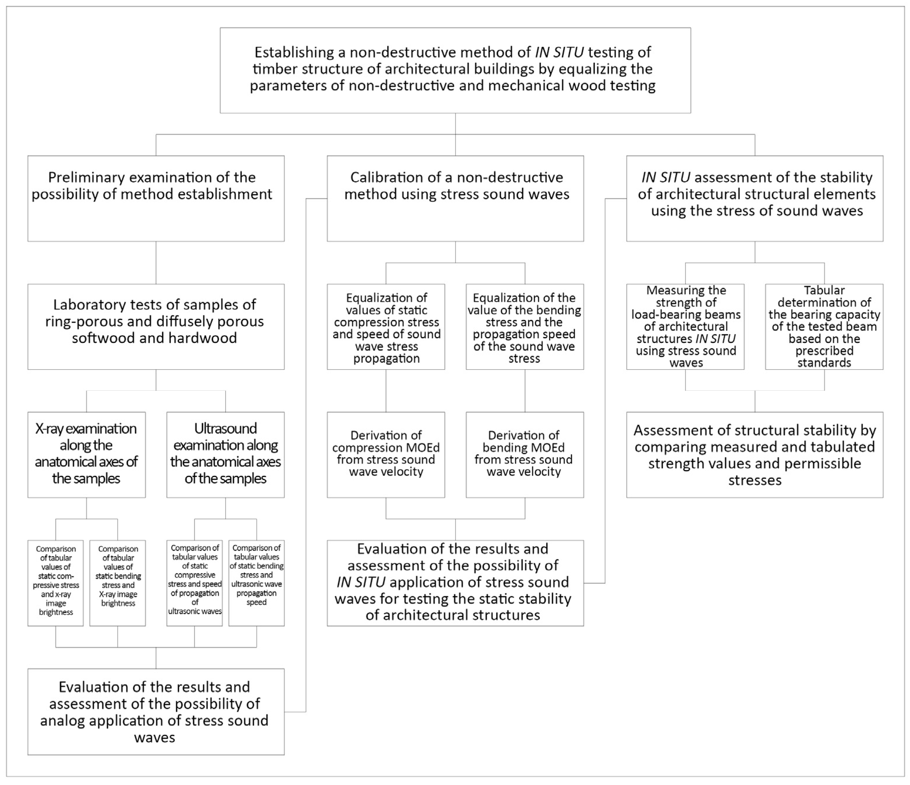
NDT methods, further discussed in [9], can effectively evaluate the condition of timber buildings without causing damage. However, it requires specialized training and equipment to be performed accurately.
The relevance of condition evaluation and ongoing monitoring of the existing timber structures has been discussed by various authors. For example, Cruz et al. [10] present guidelines for the on-site assessment of historic timber structures covering principles and possible approaches for the safety assessment of old timber structures of historical relevance that could be used as the basis for possible European Standards. On the other hand, Nowak et al. [11] present a survey of the state of the art of applying DRT methods as diagnostics techniques for testing timber structures and examples of their applications. Moreover, the paper by Gomes et al. [12] presents the assessment and diagnosis of two collar timber trusses using visual grading and NDT.
Furthermore, Stepinac et al. [13] present various methods for assessing the condition of the existing timber structures through the example of condition assessment of the Nikola Tesla Technical Museum in Zagreb. Conversely, De Matteis et al. [14] propose a design procedure for the structural assessment of ancient timber structures using resistographic NDT and apply this procedure to the case study of the Croce di Lucca Church in Naples. Significant structural flaws in the system are discovered when the roof structure’s carrying capability is assessed using the suggested experimental methods, particularly regarding the bottom tie beam.
Moreover, Wang et al. [15] propose a comprehensive evaluation method for historical timber structures and apply it to assess a typical historical Chinese timber structural building named the Fujiu Zhou house. Furthermore, Cruz et al. [16] propose joint use of non-destructive techniques, including acoustic emission, the elastic weave technique, and finite element numerical modeling, to make multi-feature decisions about repairing or replacing elements. They evaluate the effectiveness of the proposed approach on an old beam floor from a historic building in the center of Granada, Spain.
On the other hand, Martinez and Martinez [17] describe the use of infrared thermography (IRT) for the NDT assessment of a historic timber-roofed building in Madrid, Spain. Moreover, Nasir et al. [18] critically review diverse NDT methods, including spectroscopy, stress waves, guided wave propagation, X-ray computed tomography, and thermography, and introduce the concept of acoustic emission (AE) and its experimentation and analyze its possible application. Finally, Xin et al. [19] present an approach for evaluating ancient timber members’ density and mechanical properties that combines NDT, color parameters, and machine learning (ML).
A significant portion of historical architecture comprises timber floors and roofs, which must withstand vertical loads and adhere to safety regulations set forth by modern building codes. However, because it is biodegradable, wood is highly prone to harmful environmental factors, including xylophage attacks and persistently high humidity. Therefore, periodic assessments, preferably non- or minimally invasive, are required to protect old timber structures. Evaluating material properties is one of the critical steps in these assessments. Unfortunately, the previous task is not a simple one since (1) timber is a complex inhomogeneous material, (2) defects have a significant impact on a structural element’s total bearing capacity, and (3) in most cases, it may not be possible to perform comprehensive destructive testing.
Starting from the premise that it is possible to equalize the mechanical and non-destructive parameters of wood testing, the paper investigates whether the mechanical potentials of load-bearing timber beams may be immediately evaluated in situ with the stress-sound test techniques and their stability determined. The research aims to propose a reliable, non-destructive method based on equalizing the mechanical parameters of static resistance to pressure [20] and its extrapolation of the derived resistance to bending [21], the most common and most pronounced in timber structures in general [22], with the parameters of non-destructive methods, on the same standard profiled test samples. An in situ assessment of timber architectural elements of the roof structure of the Technical Faculties Building in Belgrade, Serbia, confirmed the proposed method’s effectiveness.

2. Methodologies

The research was planned and carried out in three phases (Figure 1), through a preliminary examination, calibration procedure of the non-destructive method and, finally, the immediate in situ application of the established non-destructive method.

2.1. Preliminary Examination

As wood is a heterotopic and orthotropic material [23], preliminary research was carried out using X-rays and ultrasonic waves. Analogous to mechanical testing, X-rays and ultrasonic waves were directed in the longitudinal, radial, and tangential directions of the mechanical fibers of the test samples.
The preliminary examinations showed that the achieved equalization of the mechanical parameters of static resistance to pressure and its extrapolation in the bending resistance of wood, with the parameters of ultrasound propagation speed and X-ray image brightness intensity, reflected the mechanical characteristics of a certain type of wood with identical regularity in relation to the standard anatomical directions of examination [24]. That the equalization of the parameters of mechanical and non-destructive testing of wood is a realistically feasible procedure is also confirmed by the fact that the results of research, obtained by approximating the mechanical parameters of the tested wood samples, by taking the highest mean table values, exhibit static resistance to pressure and bending, of samples of diffuse porous hardwoods, ring porous hardwoods and softwoods [25].
The fastest propagation of ultrasonic waves and the highest brightness of the X-ray image, completely analogous to the results of the static pressure resistance test, were obtained by directing the waves in the longitudinal direction of the flow of the mechanical fibers of the test samples, with their gradual reduction in the radial and tangential directions [26]. A similar regularity was also manifested for certain tree species, where the velocity of propagation of ultrasonic waves and the brightness of the X-ray image, in proportion to the table values of static resistance to pressure [27], were the highest in diffusely porous hardwood, and proportionally lower in annular porous hardwood and softwood [28] (p. 32).
Preliminary studies were carried out on standardized laboratory samples for testing the static resistance of wood to pressure, which are small in size, which enabled the principal confirmation of the functioning of the method, but due to the physical properties of scattering and weakening of ultrasonic and X-ray waves, proportional to the length of the path, their application in the third phase of testing structural elements, such as supporting wooden beams, was practically unfeasible. Taking into account the physical properties of rectilinear oscillatory sound wave propagation [27], and its negligible attenuation along the traveled path, the analogy with the methodology of conducting preliminary research could be fully achieved, with the fact that for the establishment of a non-destructive in situ method and its application, it was necessary to carry out its proper mechanical calibration.
The process of calibrating the method of applying stress sound waves should therefore be performed by directing the sound waves at right angles, analogous to the direction of static pressure forces on standard laboratory test tubes, in the longitudinal, radial, and tangential direction of the flow of mechanical fibers and compare the bending resistance values obtained by calculation [29] and by applying mechanical compression force. In this phase of the test, it was necessary to make a certain modification of the calibration procedure, because the application of stress sound waves on small test tubes for mechanical tests, as was done with X-ray and ultrasound waves in preliminary research, was not technically feasible.

2.2. Calibration of Non-Destructive Method

Calibration of the stress-sound method was performed by mechanical testing of static bending and compression stress, on standard hardwood and softwood test samples, cut from boards which were previously tested with stress-sound waves. To additionally check the correctness of the procedure, the same set of test samples from the preliminary research was not used in this test. The test samples were cut exactly from those parts of the boards through which the stress-sound wave was previously directed, so that the mechanical calibration of the method was performed on the same structure through which the sound wave went.
To equalize the test conditions on the test samples, before measuring the compressive stress, the equilibrium moisture content (EMC) and density were determined [28] (p. 190). Before the sound testing, the moisture level of the boards, which had been in the room at room temperature until that moment, was checked with a hygrometer.
The procedure of stress-sound testing is in principle similar to the one performed in preliminary research using ultrasonic waves. The values of static compressive stress obtained by mechanical testing of test samples were close to the above table values for the given type of wood [29]. Based on these values, the values of the static bending stress were determined by the relationship established between the complex bending stress and the resultant compressive and tensile stresses (compressive stress: bending stress: tensile stress; 1:2:2.8—hardwood; 1:1.5:2.5—softwood) [24]. Later, direct examination of the bending stress yielded values similar to the calculated values, which was also a confirmation of the validity of the conclusions reached in the premillennial research. The results of the mechanical calibration of the stress-sound wave method are presented in the given tables.

2.2.1. Determination of Wood Density

In this test, the wood density was calculated according to the given formula [28] (p. 213) in relation to 12% EMC of previously dried test tubes in the chamber (relative humidity—65 ± 5%; temperature 21 ± 2 °C). The test samples were previously dried because they are in a relatively stable relationship within the limits of up to 20% EMC (Kollman) [30]. The mass (m) of the test sample of each type of wood was formally measured with an electronic scale and was expressed in grams (g), and its volume was calculated according to the mathematical formula for a prismatic geometric body. The previous procedure is important for in situ testing, because within these limits, the mechanical potential of the wood does not change significantly with a change in moisture content [28] (p. 190).

2.2.2. Determination of Wood Moisture Content (MC)

Although the test samples were previously dried in the chamber, the EMC was checked immediately before their calibration, so that the stress-sound test and the determination of the static pressure stress were performed under the same conditions. EMC was determined only in standard cut test tubes so that these data could also be used as a benchmark when testing the elements of wooden structures with stress-sound waves, in the third phase of the research.
The determination of the MC of test samples and elements of wooden constructions was carried out using an electric hygrometer (SRPS EN 13163-2) because in the standard static calculations of elements of wooden architectural structures, the degree of hygroscopic MC is taken in the range of 7–25%, where this device is very reliable (Table 1) [28] (p. 212). The use of this hygrometer was also convenient because the decrease in the measuring electrical resistance of the device, by increasing the level of humidity in the range from absolutely dry to the point of fiber saturation point and, vice versa, its increase, do not require the introduction of a correction in relation to the type of wood and its density.

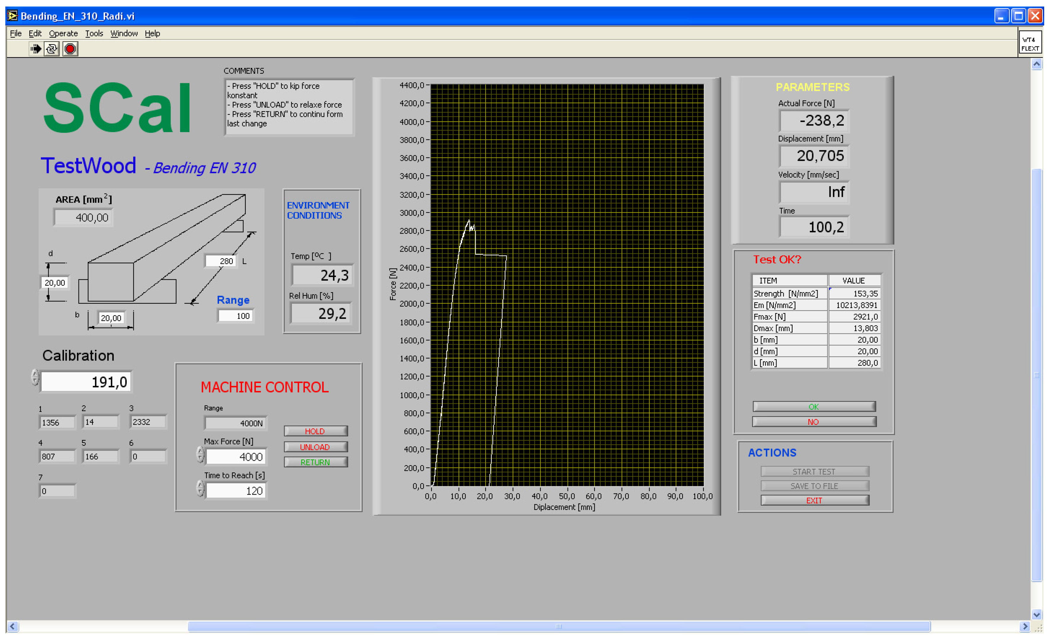
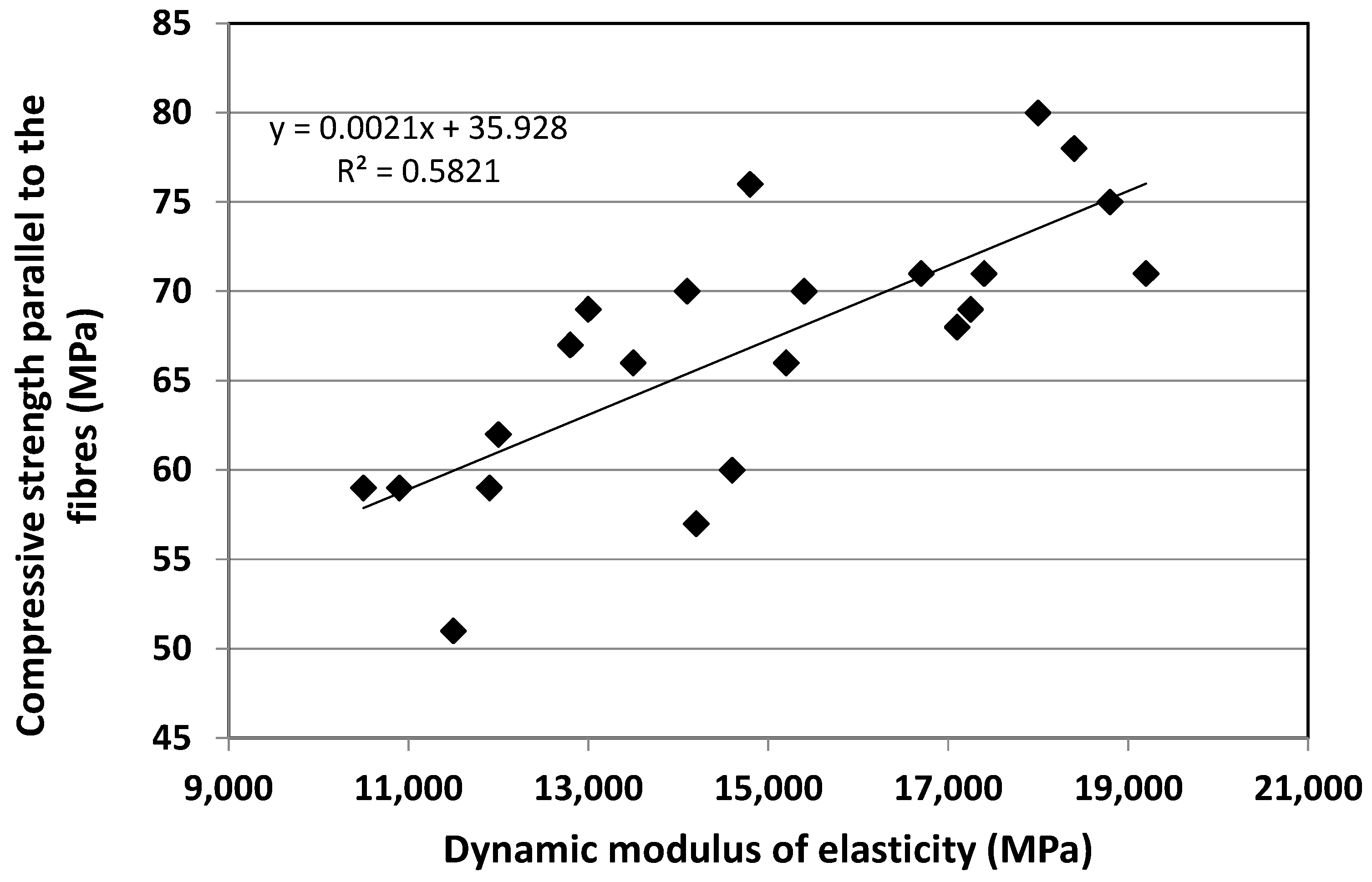
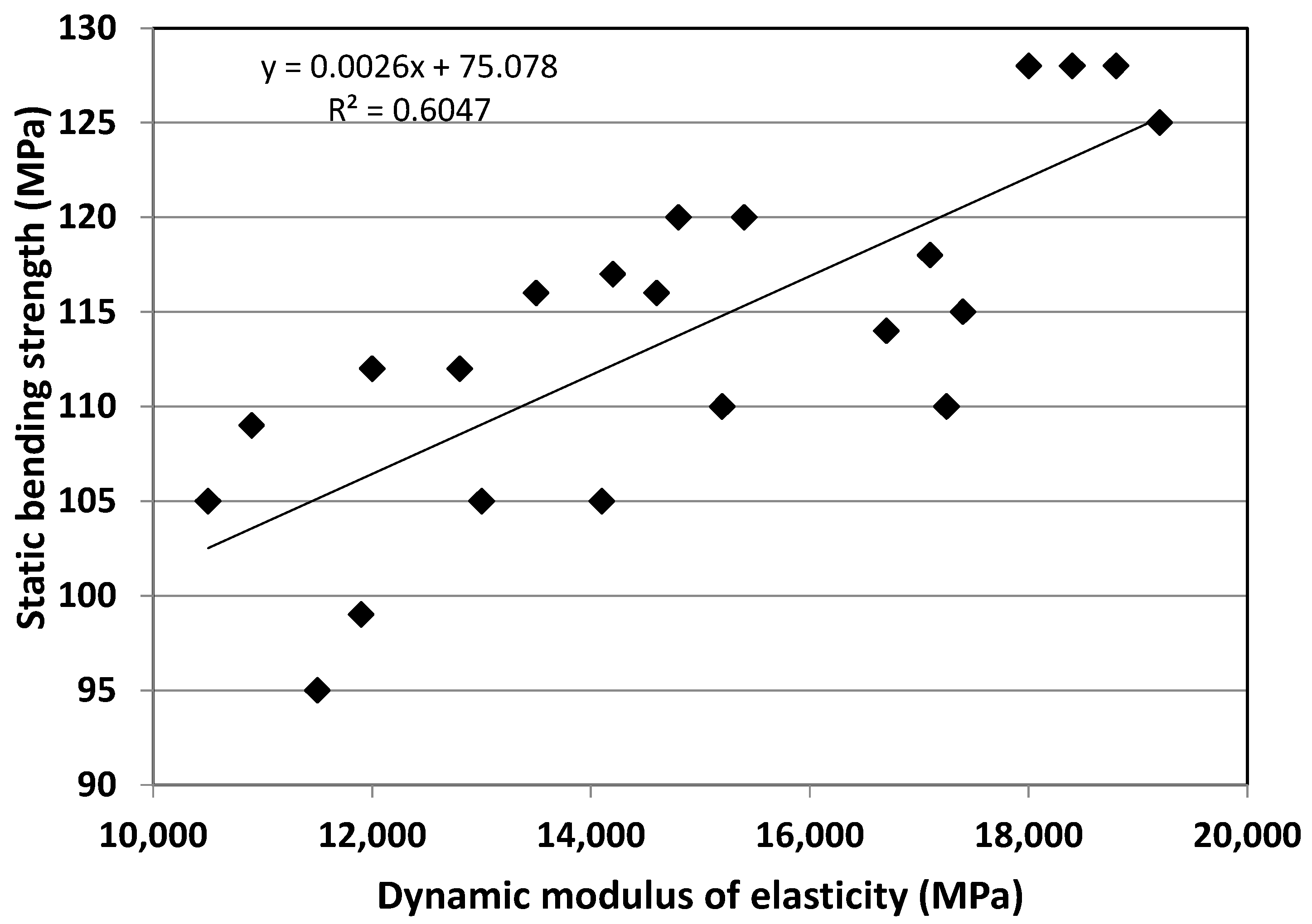
2.2.3. Determination of Compression and Bending Stresses

For this test, all test samples were of the normalized parallelopiped shape and standard dimensions SRPS ISO 13061. The calibration samples were cut in such a way that their longest side was parallel to the grain so that the plane that cut the sample longitudinally, at a right angle, parallel to the lines of the drawing, corresponded to the axial plane. Sections made by imaginary planes cutting two longitudinal adjacent sides at right angles corresponded to the radial, i.e., tangential, plane of the test sample. The test samples were cut in such a way that a corresponding projection of part of the growth ring of the wood was painted on their sides, which showed the direction of the flow of mechanical fibers, i.e., the plane of their cutting.
Calibration of test sample by applying pressure force was performed, as in the preliminary research, by directing it parallel and perpendicular to the direction of the fiber in the radial and tangential direction, as for the directions of ultrasound waves and X-rays. For the mechanical test of compressive stress, in parallel with the extension of mechanical fibers, the surface of the presser, according to the standard method, covered the entire surface of the upper side of the vertically placed test sample. When testing the compressive stress perpendicular to the grain, the presser covered the middle third of the longitudinal side of the test sample in the radial and tangential direction. The increase in the intensity of the pressure force was set to last a maximum of 5 min, and the strength of the pressure force, just before the test sample broke, was registered, equivalent to the stress at the limit of proportionality. The expression of the intensity of the compressive force was standard in N/cm/min, and the compressive stress in MPa [28] (p. 100) (see Figure 2, Table 2).
To assess the predictive potential of the stress-sound method, the dynamic flexural modulus was used (Figure 3, Table 3) as a significant indicator of the acoustic property of wood, which is calculated according to the formula based on the speed of propagation of the stress-sound wave [28] (p. 100) (Table 4 and Table 5). By correlating it with the parameters of static compressive strength and static bending strength (Figure 4 and Figure 5), correlation coefficients r-76 and r-77 were obtained, which, given that wood is an anisotropic material, can be considered very good. As the speed of sound, when it comes to wood, is not strongly dependent on the density:
c = √E/ρ,
then the dynamic modulus of elasticity (MOEdyn) can be considered a reliable predictor of the influence of bending and compression force on the wood.

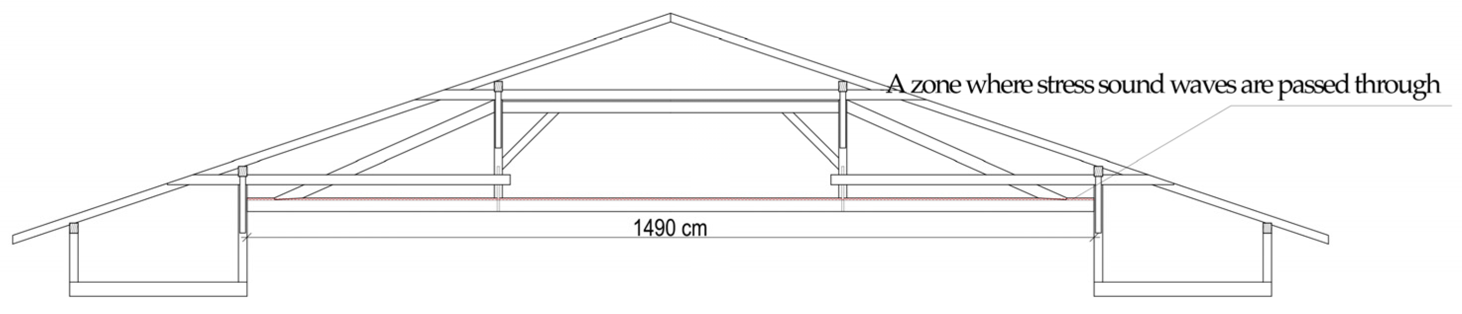
2.2.4. Stress-Sound Measurement Scheme and Equipment

In this research, the speed of stress-sound waves was measured. In the first part of the research, the measurement was performed on test samples, parallel to the grain and perpendicular to the grain in the radial and tangential directions, in a similar way as it was performed in the preliminary research using ultrasonic waves. The waves were transmitted from one side to the opposite side of the test tube mechanically, via the emissive transducer, and were registered via the receiving transducer. At the same time, the transducer function was performed by microphones, connected via a tuner to a computer program for signal analysis.

2.2.5. Stress-Sound Measurement Implementation

Waves were produced by the impact of the emission transducer on the surface of the tested sample, on the opposite side from the one on which the receiving transducer was located. Considering the small dimensions of the test sample for determining the static compressive stress, the sound test was performed on larger test tubes to determine the modulus of elasticity under pressure. The strength of the input signal was adjusted via the tuner, and the propagation speed of the sound wave was calculated based on the elapsed time between the two measurement points. The speed was determined in relation to the time and length of the path, in the same way it was used to determine the speed of conducting ultrasound:
V = L/T,
as well as to correlate the ratio, wavelength, speed, and frequency of the ultrasound wave:
Λ = V/f,
as proposed in reference [30].

2.2.6. Spectrogram

Spectral analysis of the frequency of stress-sound waves in this research was applied both in the calibration process of the method and in the in situ examination of the elements of the wooden structure. Speed and attenuation were important parameters of the calculation when evaluating the results obtained by this method. The degree of attenuation of sound wave stress is expressed by the natural logarithm of the decrease in the amplitude of the sound wave stress per unit of distance traveled using the equation:
α = l/x Ln A0/Ax,
(α attenuation factor, l-length of the wave propagation path, A0-initial wave amplitude, and Ax-wave amplitude at the end point of the distance), is directly correlated with the dynamic modulus of elasticity (MOEdyn), to consider the possibility of such behavior in situ examination phase.
Since wood is by its nature a heterotrophic and anisotropic material, the calculation of the dynamic modulus of elasticity required modifying the formula in order to obtain a true representative of wave propagation in a three-dimensional frame, which, in addition to wave speed and ρ —the wood density of the wood substance:
M O E d y n = ρ   ·   V 2
according to Newton’s general equation [30]:
V = E ρ   ( m s )
the speed of the propagating sound wave directly depends on the structural properties of the wood, i.e., from its specific density, and is directly proportional to the square root of the modulus of elasticity, and thus we had objective parameters for the immediate assessment of the strength, i.e., the load capacity of wooden structural elements based on the propagation speed of the stress sound wave.
The assessment was based on the fact that, due to decay or an excessive increase in humidity, wood loses a percentage of the content of the basic substance in its total mass, and thus its strength, so it was expected that the propagation of sound waves through damp or decayed wood (Table 5) would be significantly lower and exhibit irregular oscillation frequencies compared to the one recorded in healthy and dried wood (Table 4) [26]. These in situ measurements were made in three standard directions of the tested beam.
Table 4. The speed of propagation of stress sound waves in intact test samples.
No. of SamplesType of WoodLength
[m]
No. of
Selections
Time
[µs]
Speed
[m/s]
Thickness
[mm]
Width
[cm]
Mass
[kg]
MC
[%]
Softwood1Spruce2.055131682.292301247.2920.28.3910.3
1Fir1.9965153796.875250546.4423.98.969.6
2Fir1.79588458.333391647.2920.17.999.6
1Pine2.141136708.333302249.4423.914.387.9
2Pine2.1225161838.542253152.3923.915.697.7
Hardwood1Oak2.04108562.500362727.6117.256.6710.4
2Oak2.02111578.125349426.8121.259.039.8
1Black locust1.543103536.458287629.0812.44.1110
2Black locust1.50565338.542444528.4210.63.499.3
1Beech2.066101526.042392751.0315.612.467.3
2Beech2.099100520.833403050.0916.111.966.4
Table 5. The speed of propagation of stress sound waves in perforated test samples.
DamageNo. of SamplesTYPE OF WOODLength
[m]
No. of
Selections
Time
[µs]
Speed
[m/s]
Thickness
[mm]
Width
[cm]
Mass
[kg]
MC
[%]
11Fir1.9965141734.375271846.4423.98.969.6
11Fir1.996590468.750425946.4423.98.969.6
11Fir1.996594489.583407846.4423.98.969.6
01Oak2.04108562.500362727.6117.256.6710.4
11Oak2.04115598.958340627.6117.256.6710.4
21Oak2.04109567.708359327.6117.256.6710.4
1 + 11Oak2.02110572.917356027.6117.256.6710.4
21Oak2.04107557.292366027.6117.256.6710.4
31Oak2.04108562.500362727.6117.256.6710.4
51Oak2.04107557.292366027.6117.256.6710.4
51Oak2.04117609.375334827.6117.256.6710.4
5 + 52Oak2.04131682.292299027.6117.256.6710.4

2.2.7. Assessment of Timber Structural Elements

The approach used in this research for the in situ assessment of the structural performance of a timber structure is based on the standard allowable loads given according to the type and quality of wood (SRPS EN 1995-1-1) [31]. For modern truss wooden roof structures, the values defined by the Eurocode (EN 1991) [32] were used, calculated based on the weight of the loadbearing element and all the wooden elements of the supporting assembly.
Dimensioning of elements in the calculation of wooden structures is a concept that uses the values of their limit states, namely: limit state of elasticity—limit of failure; and usability limit state. The procedure itself is based on knowledge of technical mechanics, as well as on experimental validations. As, according to this adopted concept, the mechanically equalized parameter of the speed of sound wave progression, obtained on a wood sample of the first quality, was used for the assessment of the state of the supporting beam, the table value for the allowable compressive load, perpendicular to the wood fibers, given for the first-class wood, was taken for this in situ test.
The Eurocode (EN 1991) [32] prescribes normative values similar to these, so for trusses with a span of up to 20 m, a load of up to q = 0.25 kN/m2 is predicted, for spans of 20–25 m, that value is q = 0.35 kN/m2 and for spans over 25 m, the value q = 0.45 kN/m2 is provided. The values of the allowable load of the supporting beams according to the (SRPS EN 1995-1-1) [31] standard is shown in (Appendix A).
The assessment of the quality of the supporting beams of timber structures in the third phase of the test was intended to be performed by comparing the directly obtained, mechanically equalized, stress propagation speed parameter of the sound wave, using the calculated dynamic modulus of elasticity (MOEdyn) and its correlation with the values obtained by the static compressive and bending stress (Figure 3 and Figure 4), and the corresponding tabular values of the allowable load in N/cm2 defined by the standard.

2.2.8. Comparative Analysis of Table and Measured Load Values

This part of the research considers the limited state of static equilibrium of timber structural systems of architectural buildings based on the given values of destabilizing and stabilizing loads. The values of these loads were indirectly determined (laboratory) during the static pressure test during the calibration procedure of the experimental test tubes. By comparison, it is checked whether the measured load (destabilizing load) of the supporting structural element is excessive, in accordance with the laboratory and standardized values (stabilizing load) for timber structures (SRPS EN 1995-1-1) [31].
Based on the results of previous research, X-ray and ultrasound equivalents of static compressive stress were obtained, and by transposing tabular values, tensile, and shear stresses within the complex bending stress were obtained. According to the same principle, the parameters of the speed of propagation of stress-sound waves were reduced, with the fact that, now in this procedure, the mechanical calibration of the experimental test tubes was preceded, which achieved the establishment of a method by realistically comparing mechanical and stress-sound parameters.
The basic principle used in the assessment of static equilibrium was that the case where the result was measured on the element with the largest cross-section was valid [31]. In accordance with the recommendation and considering that the in situ research was carried out on a building with a timber structure (over 70 years old), it was acceptable that except for basic loads, other combinations of actions, such as vertical and horizontal loads, could be abstracted. In accordance with that allowable load of the structure, it would be acceptable that it is 15% higher than defined for the examined type of wood [28] (p. 170).
In order to somewhat computationally compensate the influence of abstracted additional loads (friction on bearings, temperature changes, shrinkage and swelling) and special loads (seismic, fire load), the values of the allowable stresses of the supporting beams were considered in relation to those values obtained by testing the test tubes, made of the highest quality wood. Considering the fact that the standardization of permissible stresses was established in relation to the humidity of the wood and that the test was carried out in Belgrade, it is in relation to the climatic conditions [28] in this work. A tabular model of the installed wood of the first exploitation class of 18% hygroscopic humidity was taken for calculation.

3. In Situ Measurement of the Strength of Timber Structural Elements

The results of in situ testing of the quality of the supporting beam of the timber roof structure (Figure 6) indicate that the speed of propagation of stress-sound waves, identically as in laboratory conditions, was the highest in the direction parallel to the axial axis of the supporting beam, and proportionally less along its radial and tangential direction. On the other hand, the directly measured moisture level of the beam was 10%, which meant that this circumstance, as well as the age of the beam (70 years) and the undoubted rheological influence [33,34], obtained values of the velocity of the sound wave stress through the beam, as a representative of its mechanical potential and from those points of view are considered and interpreted. Finally, due to the relatively small examined sample, it was impossible to take an absolute position in evaluating the obtained results. However, the primary goal was to present and confirm the new methodological approach to structural diagnostics.
The in situ test was carried out with an accelerometer (Bruel & Kjaer), which was used as an impulse hammer to provoke sound waves on one side of the beam, and with a measuring microphone (NTi), which registered the incoming stress-sound wave on the other side of the beam. The measuring microphone was positioned on the receiving side in a very near field, only 2 mm from beam. Both signals were recorded with the audio interface (Steinberg) with a sampling frequency of fs = 192 kHz. The minimum interval that can be registered with this device is Δt = 1/fs = 5.2083 μs. The number of samples (N) that the microphone signal receives after the provoking impulse is detected by comparing those signals. The time it takes for sound to pass through the beam was calculated by multiplying the number of samples N by the value Δt. The shortest recorded time was 2.6041 ms, and the longest was 3.1354 ms.
The maximum measured speed of the stress-sound wave along the central axial axis of the 14.9 m long beam, from the point of intersection of the diagonals of its cross-section (Figure 5), was 5721 m/s (2.6 ms), which corresponded to the time of sound passing through healthy wood (3000–5000 m/s)*, which was indicated by recording the propagation, and a gradual decrease in the wave amplitude (Table 4). By recording the wave propagation of the axial axis in 4/5* of the cross-section of the supporting beam, a gradual decrease in its amplitude was recorded, which indicated a healthy tree. That stress-sound wave velocity coefficient during axial propagation corresponded to MOEdyn of 14,744 MPa, which was obtained through the Formula (5), where ρ is the value of dense wood in absolute in a dry state V is the speed of sound passing through wood material, and ν is Poisson’s coefficient. According to the scatter line of the given graph, this MOEdyn value corresponded to a static compressive stress value of 6800 N/cm2 (68 MPa) and a static compressive stress value of 11,400 N/cm2 (114 MPa). If we consider that for our types of wood the average maximum value of bending pressure is around 100 MPa and that the limit of proportionality is 60–70% of that value, then according to the standard (SRPS EN 1995-1-1) [31] these are permissible stresses for class II European conifers, from which, according to the construction documentation, the roof structure of the building of the Technical Faculty in Belgrade was built. According to the same standard, the permissible static compressive stress perpendicular to the flow of mechanical fibers for that category of construction is 250 N/cm2 (2.5 MPa), which, according to the Eurocode standard (EN 1991) [32], even for lattice girders with a span of up to 20 m in this case, represents a certain coincidence and a kind of confirmation that the mechanical potential of the tested beam is within the limits of permissible loads.
Propagation of sound in the outer part of the upper fifth of the cross-section, along the line of the axial direction, was recorded at a lower speed (3.31354 ms) compared to the maximum (2.6 ms), recorded in the central part of the section, which indicated a defect in the structure on that line wave propagation (Table 5). Upon inspection of the beam, 10 m from the place of propagation, a slightly slanted crack with a length of about thirty centimetres was observed at the upper surface of the beam. Technically, however, the sound mapping of the cross-section was not possible on that surface due to limited access. From the findings of the inspection, the drop in the speed of sound propagation in the range of normal values, as well as the other results of the sound tests, indicating a negligible defect and healthy wood, it could be concluded that the mechanical potential of the beam is within the limits of permissible loads. Certain deviations of directly obtained values, static compressive stress, and static bending stress by comparing the non-destructive method and given tabular values could be explained by the fact that tabular average values were obtained by testing many samples and that the values of our small sample could roughly, therefore, be classified as extremes. The preservation of a very old supporting element of the timber architectural structure, with above-average mechanical potential, can be explained in this case by the rheological influence in conditions of isolation from moisture and extreme temperatures, as is the case here with the roof structure of the Technical Faculties Building in Belgrade, Serbia.

4. Discussion and Conclusions

To establish the NDT method for assessment of the quality of timber structural elements of architectural heritage buildings, all the given conditions were met according to the postulates of scientific research. This claim is based on consistently cited scientific facts related to the chemical and anatomical structure of wood, as well as the physical and mechanical properties of wood—therefore also on the laws in the behavior of wood as a material, on which the plan was conceived, and this research was carried out.
From the aspect of the methodological approach, this in situ method of examination of timber architectural structures was fully set following the valid conventional postulates for architectural buildings of cultural and historical importance. Considering that this test was successfully carried out under such conditions on the roof structure of the Technical Faculties Building in Belgrade, we can conclude that such an approach to testing guarantees respect for the given principle of preserving the authenticity and integrity of the protected object, as well as that it is generally applicable.
The presentation of other conclusions refers to examining the mechanical properties of wood. It is based on preliminary research results, laboratory establishment of the in situ method, and its immediate application. The application of X-rays and ultrasonic waves, analogous to the standard direction of the pressure force along the flow of wood fibers or perpendicular to them, confirmed the real possibility of equalization, perceptual gradation of the brightness of the X-ray image, and parameters of the speed of propagation of ultrasonic waves through the timber structure, with average table values of static stress parameters on pressure, taken for given, non-destructively tested samples—test tubes, of certain types of wood.
Based on one such numerical simulation of the mechanical testing of wood, where it was confirmed that the wood with a tabularly higher strength gave a brighter X-ray image and passed ultrasonic waves faster [5], it could be said that the mechanical calibration of any non-destructive method that can be applied analogously to the standard direction of a force in the normal stress test is feasible.
The mechanical calibration of the method of applying stress-sound waves for testing the quality of wood confirmed that this method is related to the ultrasonic method and that the results obtained by its application can be interpreted according to the same principle as in the previous reports [2,3,4]. Previous results meant that in this case, too, according to the physical laws of wave propagation, wood with a higher density, i.e., a higher value of static compressive stress (strength) and a higher dynamic modulus of elasticity (MOEdyn), will transmit stress-sound waves faster.
The calibration of the stress-sound method was carried out in conditions of standard hygroscopic humidity (12%) of test samples—test tubes, similar to the calibration of the ultrasonic method based on tabular approximation—a qualitatively new approach to in situ testing of elements of timber architectural structures was then established. Based on this, it finally follows that in equal conditions of hygroscopic humidity, the tested wooden structures will transmit stress-sound waves proportionately to their strength, thus giving a realistic reflection of their mechanical potential.
The results of the in situ tests were entirely in line with the expectations that, based on the equalization of the stress-sound wave propagation speed parameters, derived (MOEdyn) and parameters of static pressure and bending stress, obtained from test tubes made of healthy wood, can comparatively examine the mechanical potential of supporting beams of timber architectural structures. At the same time, both methods of comparison proved to be reliable in relation to the speed of stress-sound waves in healthy wood and according to the standard permissible compressive stresses for supporting wooden beams. By confirming the initial hypothetical assumptions about the possibility of equalizing the mechanical and non-destructive parameters of wood testing, we arrive at the main answer sought through this research—that the mechanical potential of load-bearing timber beams can be directly tested in situ with the stress-sound test method, and thus their structural stability.
The establishment of such a diagnostic approach, based on the equalization of the dynamic parameter of the speed of sound propagation, i.e., MOEdyn, and the parameter of static pressure and bending stress, opens the possibility of further improvement of the method. The preliminary research of this paper also shows that the principle of equalization can be applied to other NDT methods, where the diagnostic procedure is carried out analogously to the direction of the pressure force during the static pressure test. The development perspective of X-ray diagnostics is certainly of particular interest due to the possibility of direct visualization of the wood structure.
Another aspect of improving the methodology of the in situ diagnostic approach to testing the quality of wooden structures refers to introducing the degree of hygroscopic humidity as an exponential factor in the function of wave propagation speed through the wooden material. This reduces the parameters of non-destructive and mechanical testing of timber to a common denominator, which increases the precision of measurements, and, thus, the reliability of assessing the quality of built-in timber elements.
The practical application of the mechanically calibrated method of stress-sound waves could improve the process of restoration and renovation of architectural buildings of cultural and historical importance, as well as the construction process itself, primarily because of the method of application and because of a simpler choice of the suitable timber material for such purposes.

Author Contributions

Conceptualization, A.J., N.T. and J.M.; methodology, A.J., N.T. and J.M.; software, N.T., M.V. (Marko Veizović) and F.P.; validation, A.J., N.T. and J.M.; formal analysis, A.J. and N.T.; investigation, A.J., N.T., M.V. (Marko Veizović), F.P. and M.A.; resources, A.J. and N.T.; data curation, A.J. and N.T.; writing—original draft preparation, A.J. and J.M.; writing—review and editing, A.J. and J.M.; visualization, A.J.; supervision, N.T., J.M., M.V. (Miomir Vasov) and A.R. All authors have read and agreed to the published version of the manuscript.

Funding

This research was funded by the Ministry of Education, Science and Technological Development of the Republic of Serbia, grant number 451-03-68/2020-14/200090. The research was carried out under the research lab of the University of Belgrade, Faculty of Architecture—Laboratory for Innovative Structures in Architecture (LISA).

Data Availability Statement

Not applicable.

Conflicts of Interest

The authors declare no conflict of interest. The funders had no role in the design of the study; in the collection, analyses, or interpretation of data; in the writing of the manuscript; or in the decision to publish the results.

Appendix A

Table A1. Basic allowable stresses for wood moisture content of 18 and 15% in daN/cm2 for structures made of solid wood and glued laminated wood (SRPS EN 1995-1-1:2012) [31].
Permissible StressSolid Wood w = 18%Glued Laminated Wood
Stress TypeLabelSoftwoodOak, BeachSoftwoodOak, Beach
ClassClassClassClass
IIIIIIIIIIIIIII
Bendingσmd13001000700140012001400110016201370
Tensionσt‖d1050850011501000105085018001080
Compressionσc‖d110085060012001000110085015001200
Compression perpendicular to fibersσc┴d200200200300300200200
490

430
250250250400400250250
Shearingτ‖d9090901201209090150150
Shearing from T forcesτm‖d909090120120120120130110
Fiber cuttingτ┴d350300250400350350300250400

References

  1. Avdelidis, N.P.; Moropoulou, A. Applications of Infrared Thermography for the Investigation of historic structures. J. Cult. Herit. 2004, 5, 119–127. [Google Scholar] [CrossRef]
  2. Baar, J.; Tippner, J.; Rademacher, P. Prediction of mechanical properties-modulus of rupture and modulus of elasticity-of five tropical species by nondestructive methods. Maderas. Cienc. Tecnol. 2015, 17, 239–252. [Google Scholar] [CrossRef]
  3. Bachtiar, E.V.; Sanabria, S.J.; Mittig, J.P.; Niemz, P. Moisture-dependent elastic characteristics of walnut and cherry wood by means of mechanical and ultrasonic test incorporating three different ultrasound data evaluation techniques. Wood Sci. Technol. 2017, 51, 47–67. [Google Scholar] [CrossRef]
  4. Bucur, V.; Böhnke, I. Factors affecting ultrasonic measurements in solid wood. Ultrasonics 1994, 32, 385–390. [Google Scholar] [CrossRef]
  5. Keunecke, D.; Sonderegger, W.; Pereteanu, K.; Lüthi, T.; Niemz, P. Determination of Young’s and shear moduli of common yew and Norway spruce by means of ultrasonic waves. Wood Sci. Technol. 2007, 41, 309–327. [Google Scholar] [CrossRef]
  6. Kandemir-Yucel, A.; Tavukcuoglu, A.; Caner-Saltik, E.N. In situ assessment of structural timber elements of a historic building by infrared thermography and ultrasonic velocity. Infrared Phys. Technol. 2007, 49, 243–248. [Google Scholar] [CrossRef]
  7. Hussain, A.; Akhtar, S. Review of Non-Destructive Tests for Evaluation of Historic Masonry and Concrete Structures. Arab. J. Sci. Eng. 2017, 42, 925–940. [Google Scholar] [CrossRef]
  8. Fais, S.; Casula, G.; Cuccuru, F.; Ligas, P.; Bianchi, M.G. An innovative methodology for the non-destructive diagnosis of architectural elements of ancient historical buildings. Sci. Rep. 2018, 8, 4334. [Google Scholar] [CrossRef]
  9. Barnaure, M.; Cincu, M. Testing methods for the assessment of material properties in historical masonry structures: A review. Proc. IOP Conf. Ser.: Mater. Sci. Eng. 2019, 662, 032040. [Google Scholar] [CrossRef]
  10. Tejedor, B.; Lucchi, E.; Bienvenido-Huertas, D.; Nardi, I. Non-destructive Techniques (NDT) for the Diagnosis of Heritage Buildings: Traditional Procedures and Future Perspectives. Energy Build. 2022, 236, 112029. [Google Scholar] [CrossRef]
  11. Paipetis, A.S.; Matikas, T.E.; Aggelis, D.G.; Van Hemelrijck, D. Emerging Technologies in Non-Destructive Testing V, 1st ed.; CRC Press: Boca Raton, FL, USA, 2012. [Google Scholar]
  12. Jokileto, J. Aspekti autentičnosti. GDKS 2002, 26, 11–16. [Google Scholar]
  13. Klapálek, P.; Melzerová, L. Methods of Non-Destructive Assessment of Timber. Appl. Mech. Mater. 2015, 732, 369–372. [Google Scholar] [CrossRef]
  14. Cruz, H.; Yeomans, D.; Tsakanika, E.; Macchioni, N.; Jorissen, A.; Touza, M.; Mannucci, M.; Lourenço, P.B. Guidelines for On-Site Assessment of Historic Timber Structures. Int. J. Archit. Herit. 2014, 9, 277–289. [Google Scholar] [CrossRef]
  15. Nowak, T.P.; Jasieńko, J.; Hamrol-Bielecka, K. In situ assessment of structural timber using the resistance drilling method—Evaluation of usefulness. Constr. Build. Mater. 2016, 102, 403–415. [Google Scholar] [CrossRef]
  16. Gomes, I.D.; Kondis, F.; Sousa, H.S.; Branco, J.M.; Lourenço, P.B. Assessment and Diagnosis of Two Collar Timber Trusses by Means of Visual Grading and Non-destructive Tests. In Historical Earthquake-Resistant Timber Framing in the Mediterranean Area. Lecture Notes in Civil Engineering; Cruz, H., Saporiti Machado, J., Campos Costa, A., Xavier Candeias, P., Ruggieri, N., Manuel Catarino, J., Eds.; Springer: Berlin/Heidelberg, Germany, 2016; Volume 1, pp. 311–320. [Google Scholar] [CrossRef]
  17. Stepinc, M.; Rajčić, V.; Barbalić, J. Inspection and Condition Assessment of Existing Timber Structures. Građevinar 2017, 69, 869–873. [Google Scholar] [CrossRef]
  18. De Matteis, G.; Ricci, L.; Chisari, C.; Mandara, A.; Panico, S. Structural Assessment of Historical Timber Roof Trusses: The Case of the Croce di Lucca Church in Naples. In Protection of Historical Constructions. PROHITECH 2021. Lecture Notes in Civil Engineering; Vayas, I., Mazzolani, F.M., Eds.; Springer: Berlin/Heidelberg, Germany, 2022; Volume 209, pp. 1111–1125. [Google Scholar]
  19. Wang, P.; Li, S.; Macchioni, N.; Palanti, S.; Milani, G. Comprehensive Evaluation Method of Historical Timber Structural Building Taking Fujiu Zhou House as an Example. Forests 2021, 12, 1172. [Google Scholar] [CrossRef]
  20. Cruz, C.; Gaju, M.; Gallego, A.; Rescalvo, F.; Suarez, E. Non-Destructive Multi-Feature Analysis of a Historic Wooden Floor. Buildings 2022, 12, 2193. [Google Scholar] [CrossRef]
  21. Martinez, I.; Martinez, E. Qualitative Timber Structure Assessment with Passive IR Thermography. Case Study of Source of Common Errors. Case Stud. Constr. Mater. 2022, 16, e00789. [Google Scholar] [CrossRef]
  22. Nasir, V.; Ayanleye, S.; Kazemirad, S.; Sassan, F.; Adamopoulos, S. Acoustic Emission Monitoring of Wood Materials and Timber Structures: A Critical Review. Build. Mater. 2022, 350, 12887. [Google Scholar] [CrossRef]
  23. Xin, Z.; Ke, D.; Zhang, H.; Yu, Y.; Liu, F. Non-destructive Evaluating the Density and Mechanical Properties of Ancient Timber Members Based on Machine Learning Approach. Build. Mater. 2022, 341, 127855. [Google Scholar] [CrossRef]
  24. Galligan, W.J.; Courteau, R.W. Measurement of Elasticity of Lumber with Longitudinal Stress Waves and the Piezoelectric Effect of Wood. In Proceedings of the 2nd International Symposium of Nondestructive Testing of Wood, National Science Foundation, Washington State University, Pullman, WA, USA, April 1965; pp. 223–224. [Google Scholar]
  25. Gerhards, C.C. Bending Creep and Load Duration of Douglas-Fir 2 by 4s under Constant Load. Wood. Fiber. Sci. 1991, 23, 384–409. [Google Scholar]
  26. Gojković, M.; Stojić, D. Drvene Konstrukcije; Grosknjiga, Građevinski Fakultet Univerziteta: Belgrade, Serbia, 1996. [Google Scholar]
  27. Sisojević, D. Anatomija Drveta; Šumarski fakultet, Institut za Preradu Drveta: Belgrade, Serbia, 1987. [Google Scholar]
  28. Šoškić, B.; Popović, Z. Svojstva Drveta; Šumarski Fakultet Univerziteta: Belgrade, Serbia, 2002. [Google Scholar]
  29. Josifovski, A.; Savanović, D. Non-destructive testing of wood structures by X-rays. SAJ 2017, 1, 51–64. [Google Scholar]
  30. Armstrong, L.D. Effects of Moisture Changes of Crep in Wood. Nature 1965, 185, 862–863. [Google Scholar] [CrossRef]
  31. SRPS EN 1995-1-1:2012; Eurocode 5: Design of Timber Structures—Part 1-1: General—Common Rules and Rules for Buildings. Institute for Standardization of Serbia: Belgrade, Serbia, 2016. Available online: https://iss.rs/en/ (accessed on 10 March 2023).
  32. EN 1991-1-1:2002; Eurocode 1: Actions on Structures—Part 1-1: General Actions—Densities, Self-Weight, Imposed Loads for Buildings. European Committee for Standardization: Brussels, Belgium, 2002. Available online: https://eurocodes.jrc.ec.europa.eu (accessed on 10 March 2023).
  33. Popović, Z. Uticaj Vlažnosti i Temperature na Modul Elastičnosti i Savitljivost Bukovog Drveta. Master’s Thesis, Šumarski Fakultet Univerziteta, Beograd, Serbia, 1990. [Google Scholar]
  34. Pentoney, R.E.; Davidson, R.W. Rheology and the study of wood. Forest. Pro. J. 1962, 12, 243–248. [Google Scholar]
Figure 1. Flowchart of the in situ evaluation of timber structures.
Buildings 13 01405 g001
Figure 2. The graph of the ratio of applied force (N/cm2) and stress (MPa), shown on the display of the control panel of the measuring instrument, during the determination of the compression stress, in the calibration procedure of the stress-sound wave application method.
Buildings 13 01405 g002
Figure 3. The graph of the ratio of applied force (N/cm2) and stress (MPa), shown on the display of the control panel of the measuring instrument, during the determination of the bending stress, in the calibration procedure of the stress sound wave application method.
Buildings 13 01405 g003
Figure 4. The relation between the dynamic modulus of elasticity and compressive strength parallel to the fibers.
Buildings 13 01405 g004
Figure 5. The relation between the dynamic modulus of elasticity and the bending strength.
Buildings 13 01405 g005
Figure 6. Roof girder, a segment of the roof structure through which the stress-sound wave was passed.
Buildings 13 01405 g006
Table 1. Values of hygroscopic humidity and density of test samples determined in the calibration procedure of the stress sound wave method.
SoftwoodHardwood
Ring PorousDiffuse Porous
Spruce 1Fir 1Fir 2Pine 1Pine 2Oak 1Oak 2Black Locust 1Black Locust 2Beech 1Beech 2
Axial
[mm]
30.1928.9428.8129.2428.6628.9429.3229.1828.0829.4229.35
Radial
[mm]
19.7719.8219.7520.0519.9919.9319.9219.7420.1219.9519.75
Tangential
[mm]
19.7319.7819.812019.8419.8319.9419.920.3519.9419.81
Mass
[g]
5.644.724.827.846.457.739.558.558.679.18.02
Axial
[mm]
30.0828.9228.8129.1828.5828.9429.2429.1428.0329.3529.28
Radial
[mm]
19.3319.3919.3619.6119.7719.6519.6819.3719.7219.6619.49
Tangential
[mm]
18.8919.3119.2919.5619.5319.4719.4919.3319.7819.3519.41
Mass
[g]
4.924.334.427.195.917.088.817.868.028.47.41
MC
[%]
10.99.09.09.09.19.28.48.88.18.38.2
Oven-dry density
[g/cm3]
0.4480.4000.4110.6420.5360.6390.7860.7200.7340.7520.669
Table 2. Values of compressive stresses determined on test sample in the calibration procedure of the stress-sound wave application method.
SoftwoodHardwood
Ring PorousDiffuse Porous
Spruce 1Fir 1Fir 2Pine 1Pine 2Oak 1Oak 2Black Locust1Black Locust2Beech 1Beech 2
Length (mm)39.7240.239.1339.3739.139.0439.339.3239.339.4839.57
Width (mm)20.1820.1619.9620.1219.9319.9219.8619.7920.2719.9419.8
Thickness///////////
Compressive force—transversal (lateral)31131883164813,1294979414946215839473646244760
Compressive force—axial (transverse)///////////
Transversal stress3.92.32.116.66.45.35.97.55.95.96.0
Axial stress///////////
Length (mm)///////////
Width (mm)19.7510.8619.9420.0820.2919.8419.8419.9320.0219.8219.96
Thickness19.8619.8519.8920.0920.0819.7719.7919.920.1219.1919.9
Compressive force—transversal (lateral)///////////
Compressive force—axial (transverse)19,550211621,21234,21427,73924,22327,74239,24137,84231,56329,053
Transversal stress///////////
Axial stress49.853.753.584.860.061.870.798.993.980.573.1
Table 3. Values of bending stress determined on test samples in the calibration procedure of the stress sound wave application method.
SoftwoodHardwood
Ring PorousDiffuse Porous
Spruce 1Fir 1Fir 2Pine 1Pine 2Oak 1Oak 2Black Locust1Black Locust Acacia 2Beech 1Beech 2
h [mm]19.7419.8619.8420.0119.7819.8919.8519.7920.119.8819.91
b [mm]19.7219.8319.8820.1119.9119.8819.8419.9420.0619.9219.81
Bending strength MPa [N/mm2]88.979.971.6132.9102.891.09124.586.4170.3169.8128
Modulus of elasticity
MPa [N/mm2]
61088137790511,56774486792823211,02014,78811,9879145
Force max. [N]16271488133425721907170623161605328831822393
Deflection max. [mm]13.8511.7810.289.3917.9516.5815.0410.2714.512.6416.67
h [mm]19.7419.8319.8919.9820.0319.8519.9419.910.0719.919.8
b [mm]19.7819.7919.8619.9220.1419.8319.8519.9220.3119.8419.8
Bending strength MPa [N/mm2]84.181.376.9152.1119.1103.3105.8200.9185.2135.9133.3
Modulus of elasticity
MPa [N/mm2]
87848262730412,77810,3377722688215,17513,92010,3159722
Force max. [N]15441506143828802291192119873773360725422464
Deflection max. [mm]12.5811.2611.0618.2112.617.3620.0513.1614.7411.6112.59
Disclaimer/Publisher’s Note: The statements, opinions and data contained in all publications are solely those of the individual author(s) and contributor(s) and not of MDPI and/or the editor(s). MDPI and/or the editor(s) disclaim responsibility for any injury to people or property resulting from any ideas, methods, instructions or products referred to in the content.

