Abstract
The mechanism of blast damage to steel-clad concrete-filled steel tube (SCCFST) arched protective doors is studied using the dynamic response characteristics of such loads under the action of blast shock wave loads, and the ultimate blast load-bearing capacity formula is derived based on the “plastic hinge” damage mode of the doors using limit analysis, which explores the effect of the blast shock wave. The effect of the design parameters of each component of the protective door on the load-bearing capacity subjected to blast shock waves is discussed. Results show that the damage mechanism under a uniform radial load on the outer surface of the SCCFST arched protective door is characterized by the plastic hinge lines at the two arch feet, which results in a slip fracture and renders the protective door unstable. The load-bearing capacity of the SCCFST arched protective door depends on the coordinated functioning of the cross-sectional outer cladding steel plate and inner connecting partition, concrete-filled steel tube, and restraining concrete outside the steel tube. The load-bearing capacity of each of the three parts differs with the varying cross-sectional occupancies.
1. Introduction
Protective doors are important building components used to ensure the safety of personnel and property inside a building. Understanding the blast damage mechanism of protective doors and determining their limited load-bearing capacity are critical to their design and application. The available literature indicates that flat and arched doors have been studied more extensively. In order to improve the blast resistance of protective doors, several researchers have conducted experimental studies and numerical analysis using software such as ANSYS and ABAQUS to optimize the structural system and form of the doors [1,2,3,4]. Meanwhile, novel door materials or filling materials are being used to improve door performance [5,6,7,8,9,10,11]. Compared to flat doors, arched doors offer better protection for the same span and weight, are better suited to withstand dynamic impact loads, and have significant advantages in blast resistance [12]. Steel-clad concrete-filled steel tube (SCCFST) structures exhibit excellent load-bearing performance, capitalizing on the advantages offered by steel and concrete materials. Additionally, these structures are easily processable. Hence, they can be widely applied to national defense and human defense engineering [13,14,15]. Considering these attributes, a satisfactory protective effect is expected to be achieved, and this study is a step in that direction.
Li et al. [16] carried out a dynamic characteristic analysis of a double steel-clad concrete-filled arched protective door and calculated the intrinsic frequencies and corresponding vibration patterns of the door under various boundary conditions while carrying out a spectral analysis of the overpressure time-history curve of the blast shock wave in front of the door. They found that the shock wave energy was concentrated in the low-frequency interval, covering the main vibration frequencies of the door. Chen et al. [17] investigated an arched panel with a double-layered structure and numerically studied its blast load resistance and energy absorption capacity using the finite element software LS-DYNA 971, showing that this arched panel structure had a higher blast load resistance than other forms of panels. Chen et al. [18] used AUTODYN to determine the blast load on a protective door in an arched reinforced concrete test. They compared the dynamic response characteristics of the door under single and multiple loads with the test, concluding that the dynamic response of the door was mainly influenced by the non-linear contact between the door and the frame and the strain rate effect. Guo et al. [19] used ABAQUS to study the dynamic response characteristics of SCCFST protective doors under the effect of explosions, and the analysis concluded that the steel pipe inside the doors contributed greatly to the enhancement of structural resistance, while the effect of increasing the wall thickness of the steel pipe and the strength of the concrete was not obvious.
Most studies use experimental and numerical simulation methods to analyze the damage phenomena and dynamic response laws of arched protective doors and steel-clad concrete structures, but the blast damage mechanism has been studied less. This essentially limits the application of the blast resistance-bearing capacity method in engineering design. To help develop engineering applications, we conducted numerical simulations to analyze the damage mechanism of SCCFST arched protective doors subjected to blast shock waves. Based on the motorized hinge method of limit analysis, a relationship was derived for the blast resistance-bearing capacity, and the influence of section design parameters on the load-bearing performance of the protective door was analyzed.
2. Problem Formulation and Computational Model
A typical two-side-supported arched protective door system is shown in Figure 1. The protective door consists of three components: concrete-filled steel tube, confined concrete, and surrounding steel panel and separators, as shown in Figure 2.

Figure 1.
Schematic diagram of the arched protective door system.

Figure 2.
Schematic diagram of the SCCFST arched protective door. (a) Construction of the protective door. (b) Steel connections in the protective door. (c) Size of cross-section 1-1. (d) Size of cross-section 2-2.
As is shown in Figure 2b, the connection between the surface panel and its separators is realized by welding, as is the interface of the surface panel. Depending on the actual working conditions, either spot welding or welding through the length can be used. Supporting pads are used to isolate the steel tube and the surface panel, as well as the separators on the foot of the arch. After all the steel components are connected, concrete is poured inside.
In actual application, the net size of the aperture of the protective door is 3 m × 3 m. The parameters relevant to cross-section 1-1 are selected as follows: the inner diameter of the steel tube = 9.5 cm, the outer diameter = 11.5 cm, the minimum thickness of restrained concrete between the steel tube and the surrounding panel = 1.0 cm, the separator thickness = 0.5 cm, the net thickness of the concrete layer = 25 cm, the width of each cell = 25 cm, and the thickness of the surrounding panel = 1.0 cm. The number of cells other than the edge cells is denoted as n, and in this study, n = 10. The arch axis radius R = 2.325 m and the circular angle 2θ = 90° are set for the cross-section 2-2.
The protective door system in Figure 1 can be simplified using the model shown in Figure 3. Based on the symmetry, a 1/2 model is built.
Figure 3.
Schematic diagram of the numerical simulation model of the protective door.
The material properties are defined as follows: the steel is simulated using an intrinsic plastic strengthening model (Mat_Plastic_Kinematic) with yield strength = 400 MPa, density = 7850 kg/m3, and Young’s modulus = 206 GPa. The concrete is simulated using the Johnson-Holmquist-Cook plastic damage model, with the design value of compressive strength being 27.5 MPa and that of tensile strength being 2.04 MPa. High-strength reinforced concrete is selected for the door frame wall to provide sufficient support for the protective door. The Mat_Concrete_Damage model is selected for simulation, with the axial compressive strength of matrix concrete = 50.2 MPa. The reinforcement is uniformly distributed in the matrix as equivalent steel content in the concrete. The steel content is taken as 0.5%, and the yield strength of the reinforcement = 400 MPa [20].
Restraint is defined as the automatic contact between the protective door and door frame and the solid contact between the door frame and door frame wall, with a fixed-end restraint applied to the door frame wall.
The blast load is defined as a simplified sudden addition of a linear decay load without a boosting platform [16], as shown in Figure 4.
Figure 4.
Blast load curve.
in Figure 4 is the peak overpressure of the blast load (MPa). Six calculating conditions with values of 7 MPa, 10 MPa, 11 MPa, 12 MPa, 13 MPa, and 14 MPa are selected, respectively. is uniformly taken as 100 ms. The load shown in Figure 4 is applied normally to the blast surface of the protective door and the door frame wall.
3. Dynamic Response Law and Damage Mode of the Protective Door under Blast Load
By analyzing the dynamic response law and damage mode of the protective door under different , the damage mechanism of the protective door subjected to a blast load provides a basis for theoretical calculation.
3.1. Dynamic Response Law of Protective Door
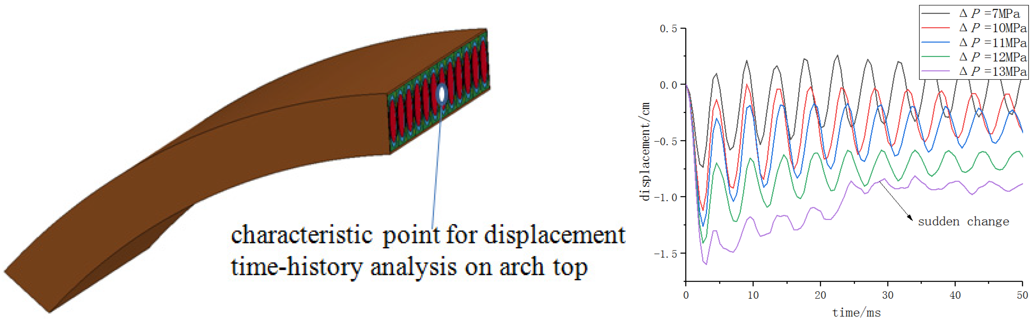
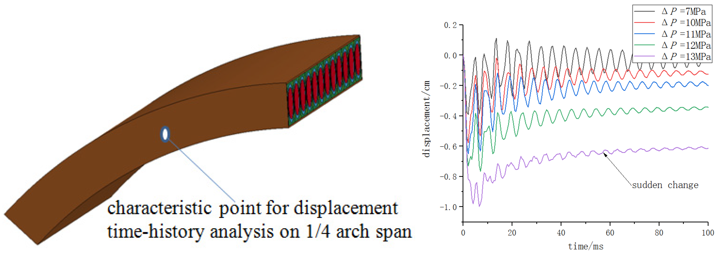
For the SCCFST arched protective door, the changes in the displacement of the arch top and 1/4 arch span position can represent the dynamic response law well [21]. Therefore, the arch top and 1/4 arch span positions are taken as the characteristic points for the displacement time-history analysis under different .
Figure 5 shows that at the top of the protective door arch, when is 7 MPa, the displacement time-history curve oscillates regularly about the zero scale, which shows the elastic dynamic response of the protective door. When is 10 MPa–12 MPa, the displacement time-history curve of the top of the arch is generally below the zero scale. After reaching the peak of negative displacement, it still presents regular damped vibration, which indicates the stable elastic-plastic vibration of the protective door. When reaches 13 MPa, there is a sudden change in the displacement time-history curve of the arch top, and there will no longer be stable vibration after reaching the peak of negative displacement. This indicates imminent plastic instability. Figure 6 shows that the displacement time-history change law on the 1/4 arch span is similar to that of the arch top, and there is a sudden change in the shape of the displacement time-history curve when reaches 13 MPa. This phenomenon coincides with the results observed by Budiansky and Roth in their study of the dynamic stability of spherical shells. They observed that, for a certain load level, when a small increment of the load causes a large change in the displacement response of the structure, the structure undergoes dynamic buckling, i.e., instability at the extreme point, and the corresponding load is referred to as the dynamic damage critical load [22]. This problem is also associated with a sudden change in the shape of the displacement time-history curve at the characteristic point when is between 12 MPa and 13 MPa. Then, the corresponding to the instant of sudden change can be considered as the ultimate load that the protective door can withstand.
Figure 5.
Displacement time-history on the top of the SCCFST arched protective door.

Figure 6.
Displacement time-history on 1/4 arch span of the SCCFST arched protective door.
3.2. Damage Mode of the Protective Door
For observation and analysis, an element from the middle of the protective door is selected, and the damage phenomena and damage mode are analyzed for each component. See Figure 7.
Figure 7.
Schematic diagram of the components of a cell of the protective door. (a) Inner concrete (b) Steel tube (c) Confined concrete (d) Surface panel and its separators.
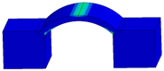
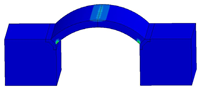
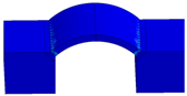
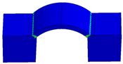
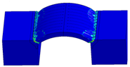
Two typical working conditions of = 10 MPa and = 12 MPa are selected, and the damage phenomena of each component in the protective door cell are presented in Figure 8 and Figure 9:(In the figures, e refers to ×, e.g., 8e+03 refers to 8 × 10³).
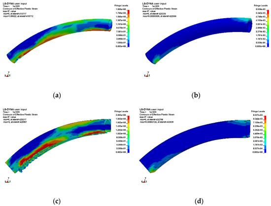
Figure 8.
Effective plastic strain distribution of each component of the protective door when
= 10 MPa. (a) Inner concrete. (b) Steel tube. (c) Confined concrete. (d) Surface panel and its separators.
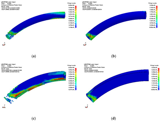
Figure 9.
Effective plastic strain distribution of each component of the protective door when
= 12 MPa. (a) Inner concrete. (b) Steel tube. (c) Confined concrete. (d) Surface panel and its separators.
The loading time of the two figures above is uniformly taken as the end of the simulation, i.e., 100 ms. Under the blast load of = 10 MPa, the inner concrete basically does not appear to be damaged. The confined concrete is dislodged on the tensile side, and the steel tube, surface panel, and separators enter the plastic state at the top and the foot of the arch in a part of the section. When = 12 MPa, the inner concrete and confined concrete at the foot of the arch are fractured, and the steel tube, surface panel, and separators show concentrated plastic strain distributions at the foot of the arch, indicating the trend of the plastic state of the entire section. Under the two different blast loads, the damage mode of the protective door is changed. When = 10 MPa, the protective door is damaged to some extent at the top and foot of the arch, but the damage limit is not yet reached. When = 12 MPa, the protective door suffers serious damage, mainly in the arch foot, which is close to the damage limit.
Additional working conditions have been selected, and the description of damage characteristics under each blast load is summarized in Table 1:

Table 1.
Damage situation of protective doors under different .
Table 1 shows that with the increase in , the degree of damage to the SCCFST arched protective door gradually aggravates. The value of is less than 11 MPa when the protective door shows the overall deformation response mode in which the load causes a continual increase in damage. This is evidenced by the deformation of the arch foot leading to the slip fracture damage mode. Combined with the description of the dynamic response of the protective door displacement in Section 3.1, it can be deduced that the door becomes dynamically unstable when the “plastic hinge” is formed at the foot of the arch, and the structure becomes a geometrically unstable system that reaches the limit of its load-bearing capacity.
3.3. Damage Mechanism of the Protective Door
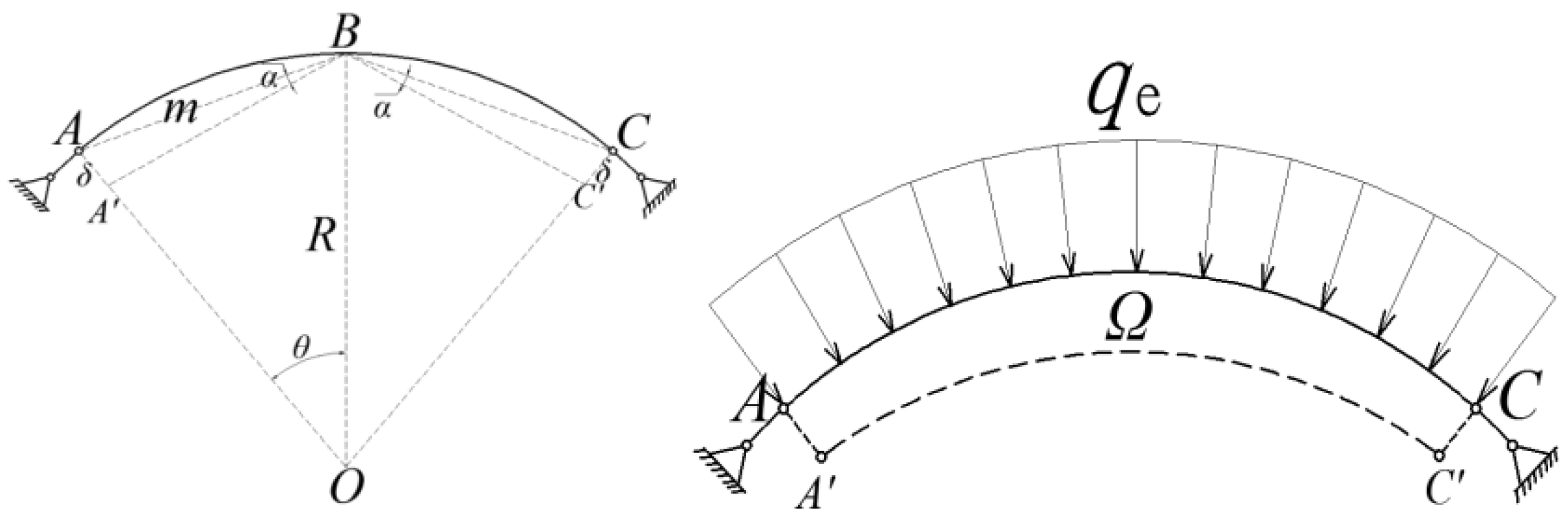
According to the analysis results presented in Section 3.2, under large blast loads (11 MPa), the regions of plastic damage are mainly located at the foot of the arch. In practical engineering design, it is necessary to consider the situation where the door is subjected to large blast loads, making the arch foot the most susceptible to damage, and the damage limit of the arch determines the load-bearing capacity of the door. According to the yield line theory [23], the plastic hinge formed at the foot of the arch when subjected to a radial blast load uniformly distributed on the outer surface is, by definition, the yield line. The protective door slides and collapses along the yield line and eventually becomes a geometrically unstable system. The diagram of the yield line is as follows:
The damage can be modeled using the maneuver method of limit analysis. If the SCCFST structure is considered an ideal elastic-plastic material, the structure will enter the plastic flow state when the load reaches a certain value. Using the upper limit theorem, the upper limit of the ultimate load can be determined by equating the internal work in the maneuvering tolerance field to the external work. The specific calculation method is shown in Section 4.
4. Theoretical Calculation of Ultimate Blast Resistance-Bearing Capacity of the Protective Door
4.1. Mechanical Model
In the motorized hinge method of limit analysis, each yield line in Figure 10 is integrated to establish the virtual work equation, where the external work performed by the uniform load is given by
where, is the load per unit area, is the displacement per unit area along the direction of the load, and is the area of the load-acting surface.
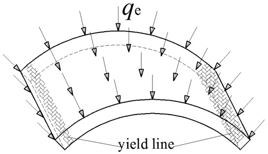
Figure 10.
Schematic diagram of yield line.
The internal work performed by the cross-sectional internal force along the yield line is:
where, is the normal turning angle, is the unit width of the section limit bending moment, and l is the yield line length, i.e., the section width.
From the geometry,
W = D
According to the principle of imaginary displacement, a normal imaginary displacement δ is applied at each yield line, as shown in Figure 11:

Figure 11.
Calculation sketch of the arched protective door.
The bending moment at the two plastic hinges is such that .
Since α is very small, it can be approximated as
Then, the work performed by the internal force along the yield line is:
The work performed by the external load can be expressed as:
where, Ω is the area formed by the movement of the protective door in the unit width of the cross-section 2-2.
Substituting Equations (6) and (7) into (3), we obtain the expression for the ultimate static load that the protective door can withstand:
To obtain the ultimate blast load that the protective door can withstand, a dynamic coefficient is introduced, which is the ratio of the dynamic effect of the blast load on the protective door to the equivalent static load required to produce the same response in the system. The equivalent static load on the system is:
For the elastic-plastic system subjected to the sudden addition of linear decay load shown in Figure 4, the value of is related to the load action time , structural self-oscillation circular frequency , and allowable ductility ratio as follows [24]:
For steel-concrete composite structures, is often taken as 3.
In Equation (10), tends to be 1.2 when . The arched protective door considered in this study is consistent with such a situation.
4.2. Ultimate Bending Moment of Cross-Sectional
The ultimate bending moment of the cross-section of the protective door is the positive cross-sectional bending-bearing capacity. It has three components associated with the concrete-filled steel tube, the steel frame that connects the surrounding steel panel and separators, and the confined concrete between the steel tube and steel frame, respectively. Here, the concrete-filled steel tube and separators can be seen as a unified steel bone. The following basic assumptions are satisfied for the calculation [25]:
- (1)
- Steel and concrete have flat sections with respect to deformation;
- (2)
- The plot of stresses in the compressed zone within the concrete can be simplified to an equivalent rectangle;
- (3)
- The plots of tensile and compressive stresses in the steel bones are trapezoidal, which can be simplified to an equivalent rectangle in calculation;
- (4)
- The tensile strength of the concrete is ignored.
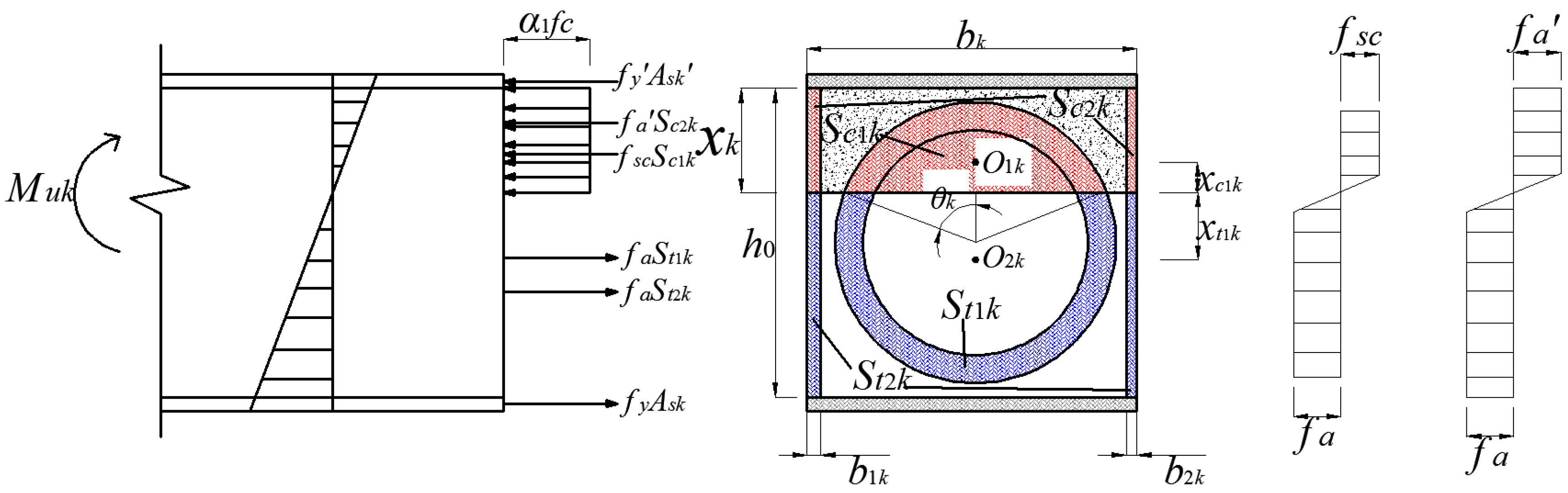
The SPSPC section can be divided into (n + 2) subsections or cells as indicated in Figure 2, and the calculation sketch for each sub-section is shown in Figure 12.
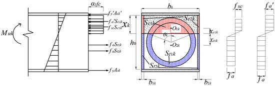
Figure 12.
Calculation Sketch of ultimate bending moment of SPSPC section.
According to the force balance:
where, is the concrete strength subfactor. When the strength does not exceed 50 MPa, is taken as 1.0; when the strength does not exceed 80 MPa, is taken as 1.0. Elsewhere, is determined by linear interpolation between 50 MPa and 80 MPa; is the axial compressive strength of concrete; is the equivalent width of the concrete compression zone of the k calculated section given by
where is the width of the concrete section of the k calculated section; is the height of the concrete compression zone of the k calculated section; , are the design values of compressive and tensile strength of the surrounding panel; , are the area of the panel in compression and in the tension of the k calculated cross-section; , are the design values of the compressive and the tensile strength of the steel bone; is the compressive strength of the combined section of the concrete-filled steel tube.
According to the standard DL/T5085-2021 [26],
In Equation (11), ; is the concrete-filled steel tube confinement factor, and ; is the steel tube cross-sectional area in the concrete-filled steel tube; is the concrete cross-sectional area in the concrete-filled steel tube; , are the area of the concrete-filled steel tube in the compression zone and tension zone of the kth calculated section.
From the geometry,
, are the area of the separators (or surrounding side panel) in the compression zone and tension zone of the kth calculated section;
, are the width of steel bone on two sides of the kth calculated section. When , , ; when , , ; when k is taken as else, ; , are the distance from the mass center of the concrete-filled steel tube in the compression zone and the mass center of the concrete-filled steel tube in the tension zone to the neutral axis of the kth calculated section.
The ultimate bending moment of the SCCFST section can be derived using the summation formula:
4.3. Analysis of Calculation Results
The ultimate blast resistance-bearing capacity of the protective door can be derived using Equations (8), (9), (11) and (16).
The numerical examples presented in Section 2 are solved using the theoretical methods described in this section.
The of the C60 concrete is 27.5 MPa and is 0.98, while the of steel is 400 MPa.
In this case, the ultimate blast resistance of the SCCFST arched protective door is 11.28 MPa by the theoretical method. According to the numerical simulation, the ultimate load capacity range obtained is 12–13 MPa, and the results of the theoretical calculation are slightly lower than those of the numerical simulation, but the relative error does not exceed 13%. The reason for this phenomenon is that the theoretical calculation considers only the confinement effect of the steel tube for the concrete inside, whereas the confinement effect of the surrounding panel and its separators for the confined concrete is ignored.
5. Analysis of the Impact of Design Parameters on the Ultimate Blast Resistance-Bearing Capacity
The cross-section of the SCCFST arched protective door consists of a concrete-filled steel tube, a steel frame connected with the surrounding panel and its separators, and a confined concrete section between the steel tube and the steel frame. Changing the design parameters related to any of these components will affect the blast resistance. In this section, the design parameters related to each component are varied. Using the calculation method proposed in Section 4, the effect of these changes on each component of the blast resistance-bearing capacity of the protective door is analyzed.
5.1. Influence of Concrete-Filled Steel Tube Design Parameters
From (13), it can be seen that the factors that influence the strength of the combined section of a concrete-filled steel tube include the outer diameter of the steel tube, the wall thickness of the steel tube, the strength of the steel tube, and the strength of the concrete.
For ease of comparison, the dimensional parameters of each component are expressed in terms of the steel ratio (section occupancy) , and it is the percentage of the cross-sectional area of each component to the cross-sectional area of the protective door, which is as follows:
Steel ratio of steel tube:
Occupancy of concrete-filled steel tube section:
Steel ratio of surrounding panel and separators:
Since the outer diameter and wall thickness of the steel tube determine the geometric dimension of internal concrete, the section occupancy of the pipe and the steel ratio of the pipe are analyzed first.
At = 19.42%, the corresponding relationship between different section occupancies of the concrete-filled steel tube and the blast resistance of the protective door is shown in Figure 13. At = 61.14%, the corresponding relationship between the different section occupancies of the steel tube and the blast resistance of the protective door is shown in Figure 14.
Figure 13.
Effect of
on the protective door load-bearing capacity.
Figure 14.
Effect of
on the protective door load-bearing capacity.
The relationship between the strength of the steel tube and the load-bearing capacity of the protective door is shown in Figure 15, and the relationship between the strength of the concrete inside the steel tube and the load-bearing capacity of the protective door is shown in Figure 16.

Figure 15.
Effect of steel tube strength on the protective door load-bearing capacity.
Figure 16.
Effect of the strength of the concrete in the steel tube on the protective door load-bearing capacity.
From Figure 13, Figure 14, Figure 15 and Figure 16, it can be observed that an increase in the section occupancy of the concrete-filled steel tube and steel tube strength can improve the blast load-bearing capacity of the protective door, whereas an increase in the steel ratio of the concrete-filled steel tube strength inside the steel tube in a certain interval has a negative effect on the blast load-bearing capacity of the protective door. This is because the confinement coefficient is an important factor that affects the strength of the combined structure when the concrete-filled steel tube is considered a composite structure. According to Equation (13), if the confinement coefficient is too large, the composite structure of the concrete-filled steel tube cannot perform as well, and it will result in a decrease in strength. Therefore, the wall thickness and strength of the steel tube and the concrete strength should be controlled within the appropriate range. Without changing the steel ratio, in comparison, the outer diameter of the steel tube can be increased to improve the blast resistance. This approach can make full use of the confinement of the steel tube on the concrete and offers an economical solution. Hence, it is advisable to maximize the increase in the outer diameter of the steel tube.
5.2. Influence of Design Parameters of Confined Concrete
The geometry of the confined concrete changes with that of the steel tube, surrounding panel, and separators. Thus, the effect of the geometry of confined concrete on the blast resistance is not considered in this subsection, and only the effect of changes in the concrete strength is analyzed, as shown in Figure 17.
Figure 17.
Effect of the strength of confined concrete on the protective door load-bearing capacity.
It can be seen from Figure 17 that as the strength grade of the confined concrete increases from C50 to C80, the load-bearing capacity of the protective door also rises slowly, but has been maintained at about 11.3 MPa, and the change is not obvious.
5.3. Influence of Design Parameters of the Surrounding Panel and Its Separators
The variable design parameters of the surrounding panel and separators are the steel ratio and steel strength, which do not change the thickness of the separators. The steel ratio is changed by adjusting the thickness of the surrounding panel. The influence of these two parameters on the blast resistance of the protective door is illustrated in Figure 18 and Figure 19.
Figure 18.
Effect of
on the protective door load-bearing capacity.

Figure 19.
Effect of steel strength on the protective door load-bearing capacity.
From the two figures above, it can be seen that increases by 75.5% when the steel ratio increases by 11.71% and by 36.8% when the steel strength is nearly doubled.
6. Conclusions
The following conclusions can be drawn from the study described herein:
- (1)
- Under a radially uniform load on the outer surface, as the load increases, the SCCFST arched protective door supported on both sides shifts from the overall deformation reaction mode into the development of a plastic hinge line at the foot of the two arches, resulting in dynamic instability. The protective door becomes a geometrically unstable system and eventually fails due to slip fracture damage.
- (2)
- This paper proposes a method for calculating the ultimate blast resistance of the SCCFST arched protective door based on the motorized hinge method of ultimate analysis. This method considers the geometric relationship between the “plastic hinge” damage mode of the door and the coordinated action of the components of the door section and can be used for the design and analysis of protective doors against blast load.
- (3)
- The impact of the design parameters of each part of the SCCFST arched protective door on the ultimate blast resistance-bearing capacity has a clear pattern: (A) The primary factor influencing the ultimate blast resistance is the surrounding panel and its separators. Hence, increasing the steel ratio and steel strength can significantly increase the ultimate blast resistance load capacity. (B) The concrete-filled steel tube contributes to the ultimate blast resistance to a lesser extent. Enhancing the steel ratio and strength of the steel tube within a certain range can moderately improve the ultimate blast resistance. (C) While confined concrete plays a role in the ultimate blast resistance capacity, the impact of increasing the concrete class on the load-bearing capacity is not particularly pronounced.
Author Contributions
Conceptualization, S.D. and Z.T.; methodology, S.D. and Z.T.; software, S.D.; validation, X.C., C.T. and Z.W.; formal analysis, C.T.; investigation, C.T.; resources, X.C.; data curation, Z.W.; writing—original draft preparation, S.D.; writing—review and editing, Z.T.; visualization, X.C.; supervision, Z.W.; project administration, Z.T.; funding acquisition, Z.T. All authors have read and agreed to the published version of the manuscript.
Funding
This research received no external funding.
Data Availability Statement
The raw/processed data required to reproduce these findings cannot be shared at this time as the data also form part of an ongoing study.
Conflicts of Interest
The authors declare no conflict of interest.
References
- Jacques, E.; Lloyd, A.; Berry, T.; Saatcioglu, M.; Shinder, J. Development of blast resistant steel doors. In Proceedings of the 11th International Conference on Shock & Impact Loads on Structures, Ottawa, ON, Canada, 14–15 May 2015; pp. 14–15. [Google Scholar]
- Meng, Y.; Li, B.; Wang, Y. Structure design of new airtight blast door based on topology and shape optimization method. Geotech. Geol. Eng. 2016, 34, 703–711. [Google Scholar] [CrossRef]
- Veeredhi, L.S.B.; Ramana Rao, N.V. Studies on the impact of explosion on blast resistant stiffened door structures. J. Inst. Eng. Ser. A 2015, 96, 11–20. [Google Scholar] [CrossRef]
- Thimmesh, T.; Shirbhate, P.; Mandal, J.; Sandhu, I.; Goel, M. Numerical investigation on the blast resistance of a door panel. Mater. Today Proc. 2021, 44, 659–666. [Google Scholar] [CrossRef]
- He, H.; Zhang, B.; Zheng, Q.; Fan, H. Anisotropic dynamic theory to predict blast responses of composite fluted-core sandwich protective door panels. Thin-Walled Struct. 2021, 161, 107436. [Google Scholar] [CrossRef]
- Li, X.; Miao, C.; Wang, Q.; Geng, Z. Antiknock performance of interlayered high-damping-rubber blast door under thermobaric shock wave. Shock. Vib. 2016, 2016, 2420893. [Google Scholar] [CrossRef]
- Zhang, B.; Chen, H.; Zhao, Z.; Fan, H.; Jin, F. Blast response of hierarchical anisogrid stiffened composite panel: Considering the damping effect. Int. J. Mech. Sci. 2018, 140, 250–259. [Google Scholar] [CrossRef]
- Meng, F.; Zhang, B.; Zhao, Z.; Xu, Y.; Fan, H.; Jin, F. A novel all-composite blast-resistant door structure with hierarchical stiffeners. Compos. Struct. 2016, 148, 113–126. [Google Scholar] [CrossRef]
- Zhang, Y.; Fan, J.; Tao, J.; Jia, X.; Huang, Z.; Liu, X.; Liang, S.; Zhao, Y.; Bai, X. A sutdy on impact resistance performance of a blast door with POZD coating. J. Vib. Shock. 2022, 4, 231–238. (In Chinese) [Google Scholar]
- Shi, S.; Zhang, X.; Yin, P. Static Analysis of the New Defensive Structure under Explosive Loading. Undergr. Space 2003, 23, 66–68+109. (In Chinese) [Google Scholar]
- Ganorkar, K.; Goel, M.D.; Chakraborty, T. Numerical Analysis of Double-Leaf Composite Stiffened Door Subjected to Blast Loading. J. Perform. Constr. Facil. 2023, 37, 04022067. [Google Scholar] [CrossRef]
- Tan, Z. The Dynamic Response and Optimum Design of Vaulted Blast Resistant Door; Chang’an University: Xi’an, China, 2015. [Google Scholar]
- Manojkumar, V.C.; Mattur, C.N.; Kulkarni, S.M. Axial strength of circular concrete-filled steel tube columns-DOE approach. J. Constr. Steel Res. 2010, 66, 1248–1260. [Google Scholar]
- Chung, K.; Park, S.; Choi, S. Material effect for predicting the fire resistance of concrete-filled square steel tube column under constant axial load. J. Constr. Steel Res. 2008, 64, 1505–1515. [Google Scholar] [CrossRef]
- Jiang, Z.; Sun, S.; Lu, H.; Yu, S. Analysis of dynamic response and influence factors of concrete-filled steel and steel tube blast doors. J. Ordnance Equip. Eng. 2022, 43, 41–47. (In Chinese) [Google Scholar]
- Li, E.; Sheng, X.; Wang, J. Dynamic analysis of vaulted protective doors under nuclear and conventional blast loadings. Prot. Eng. 2011, 33, 16–21. (In Chinese) [Google Scholar]
- Chen, W.; Hao, H. Numerical study of a new multi-arch double-layered blast-resistance door panel. Int. J. Impact Eng. 2012, 43, 16–28. [Google Scholar]
- Li, C.; Qin, F.; Zhang, Y.-D.; Zhang, Y.; Fan, J.-Y. Numerical and Experimental Investigations on the blast-resistant properties of arched RC blast doors. Int. J. Prot. Struct. 2010, 1, 425–441. [Google Scholar]
- Guo, D.; Li, Z.; Wang, Q.; Hou, X. Research on blast-resistant properties of concrete-filled steel and steel tube blast doors. Prot. Eng. 2013, 35, 38–43. (In Chinese) [Google Scholar]
- LS-DYNA Keyword User’s Manual; LSTC: San Francisco, CA, USA, 2017.
- Xu, Y.; Hu, S. A study on the dynamic ultimate capacity of CFST arch bridges. China Civ. Eng. J. 2006, 39, 68–73. (In Chinese) [Google Scholar]
- Budiansky, B.; Roth, R.S. Axisymmetric Dynamic Buckling of Clamped Shallow Spherical Shells. NASA TN 1962, 510, 597–606. [Google Scholar]
- Shen, J.; Wang, C.; Jiang, J. Finite Element of Reinforced Concrete and Limit Analysis of Shell; Tsinghua University Press: Beijing, China, 1993. [Google Scholar]
- US Department of the Army. TM5-1300 Structures to Resist the Effects of Accidental Explosions; US Department of the Army: Washington, DC, USA, 1990. [Google Scholar]
- Ma, H.; Wang, T. Combination Structure of Steel-Concrete; Building Materials Industry Press: Beijing, China, 2006. [Google Scholar]
- DL/T5085-2021; Code for Design of Steel-Comcrete Composite Structure. Department of Transportation: Beijing, China, 2021.


Disclaimer/Publisher’s Note: The statements, opinions and data contained in all publications are solely those of the individual author(s) and contributor(s) and not of MDPI and/or the editor(s). MDPI and/or the editor(s) disclaim responsibility for any injury to people or property resulting from any ideas, methods, instructions or products referred to in the content. |
© 2023 by the authors. Licensee MDPI, Basel, Switzerland. This article is an open access article distributed under the terms and conditions of the Creative Commons Attribution (CC BY) license (https://creativecommons.org/licenses/by/4.0/).