1. Introduction
Heat storage technologies are crucial for providing internal comfort conditions for building occupants [
1,
2,
3,
4,
5]. The benefits of thermal mass can be equally beneficial in both residential [
4,
6,
7] and commercial buildings [
2]. Thousands of years of architectural history show that buildings utilizing conventional thermal mass (stone, earth constructions, brick, adobe, solid wood, etc.) can provide excellent thermal comfort conditions, even in extremely hot or desert climates [
3,
8]. A large volume of research worldwide has already demonstrated that both conventional thermally massive and PCM-enhanced building components can be helpful in modifying buildings’ dynamic thermal responses and therefore their whole-building energy use characteristics [
1,
3,
4,
7,
8,
9,
10,
11]. These technologies have become an integral part of sustainable design, as have the management strategies for control of whole-building energy usage and interactions with the power grid [
2,
10].
As a result of their scale of energy consumption, buildings play a very important role in today’s energy economy and energy conservation policies. A great variety of PCM building applications have been introduced and evaluated, including building envelopes, internal building fabric, space conditioning systems, water heating, and building-scale energy storage applications [
1,
3,
7]. Active thermal storage and thermally massive building components can significantly influence not only the building’s internal thermal comfort and energy consumption but also the building’s dynamic thermal response, shifts in peak load times, and moderating seasonal energy demands. Usually, control of transient responses of thermally massive building elements depends on (i) anticipated demands for reserve energy capacity, (ii) variations in renewable power generation, and/or (iii) actual dynamics in electric power grid demands [
12]. A need for a manageable interaction with these network service requirements urges the creation of control strategies for dynamic energy demands coming from individual buildings. Consequently, building thermal storage applications as well as components and systems using PCMs can be added to offer internal comfort-related, temperature control, and load management strategies [
2,
13].
A large selection of organic and inorganic PCMs has been used in numerous heat storage and building component applications [
14,
15]. This usage trend also includes heat sinks in electronics and electric vehicles (batteries), data centers, food and pharmaceutical product packaging, solar thermal systems, shipping of medical products, etc. However, three major barriers are still reported for extensive PCM applications. They are (i) the relatively high cost of some PCMs; (ii) the absence of complete and verifiable information about PCM thermal performance; and (iii) often unreliable data on the durability of PCM products.
Design optimization is believed to be one of the most effective methods for reducing costs and enhancing the performance of PCM products [
16,
17]. However, achieving this requires a thorough understanding of the thermal performance characteristics of the examined PCMs and commercial products that utilize these PCMs. Therefore, the development of accurate and simple testing methods, enabling experimental determination of the thermal characteristics of both PCMs and products containing PCMs, is critical for the further expansion and market acceptance of these technologies. To avoid mistakes in performance assessments, in the case of building applications, such analysis should be performed from the viewpoints of (i) material, (ii) system, and (iii) whole-building scales.
Both PCM system design optimization and energy performance analysis are commonly performed today using numerical tools. For thermal and energy performance analyses of building components containing PCM, a large number of numerical heat transfer and whole-building energy programs have already been developed and are commonly used. In the widely referred IEA Annex 23 work based on the survey of over 250 research publications, it was concluded that the general confidence in currently used numerical models is still too low to use them for designing and coding purposes. In addition, it was found that in many cases, the thermal characteristics of PCMs are poorly known, which creates inherent sources of inaccuracies in computer simulations [
18]. Please keep in mind that in building applications, pure PCMs are rarely used. Instead, PCM-enhanced materials, PCM-based composites, or arrays of small containers with PCMs are utilized, which yields a need for sufficiently detailed thermal performance data and detailed physical characteristics before numerical analysis can be implemented.
2. Roofs and Attic Systems as Complexity Examples
Both passive and active thermal storage and conventional thermal mass systems can significantly influence not only the internal thermal comfort and energy consumption but also the building’s dynamic thermal response, shifts in peak load times, and moderating seasonal energy demands. Since roof and attic systems are exposed to the highest temperature fluctuations of all building components, their role in controlling internal comfort conditions inside the building cannot be overseen [
19]. In addition, roofs and attics are also one of the most complex building applications because of their multidimensional heat transfer effects, strong dynamic solar loads, and combined air and moisture transport. In spite of the fact that a large volume of experimental data is available for PCMs used in roofs and attics in a wide range of climatic conditions, for designing and optimization purposes, numerical analysis can be primarily important.
Depending on the considered design configuration and material applications, different types of numerical models can be utilized for the analysis of latent heat storage and thermally massive systems. In the case of thermal and energy usage analyses, these models need to be based on detailed experimental data, reflecting often complex, system-scale characteristics. They also need to reflect the common geometric complexity of multi-material PCM storage components. If combined with thermal bridging caused by structural and attachment elements, heat transfer in these components may have a strong three-dimensional character [
20,
21]. To reflect these facts, sufficient supporting experimental data needs to be developed.
2.1. Building Systems Using Composites and Blends Containing PCM
Advanced roofs and attic configurations usually contain thick layers of thermal insulation, which is often assisted with radiant barriers and air ventilation strategies. In addition, radiant barriers and heat storage components are used to enhance their thermal performance in different climatic conditions. The level of thermal performance improvements available with the introduction of building envelope components containing PCMs depends on the quantity of PCM that is used, its physical characteristics, climate conditions, and a general building design. A detailed whole-building energy model, including thermal and energy effects in building envelopes using PCMs, is important for the evaluation of their thermal behavior and prospective energy benefits. A comprehensive numerical analysis, including system-scale simulations of PCM-enhanced envelope components, is often needed to understand these systems’ impact on internal comfort conditions. Sometimes, however, simplified algorithms are preferred because they can quickly estimate the influence of PCMs’ thermal performance. They all require an accurate set of thermophysical characteristics for PCMs and PCM-based systems. That is why the development of test-based material characteristic information is a critical enabling factor for the wide market acceptance of many PCM building products.
2.2. Heat Transfer in Composites and Thermal Insulation Containing PCM
A variety of basic theoretical algorithms for temperature-dependent specific heat problems can be applied in the assessment of phase change processes in commonly used PCM-enhanced building components [
22,
23,
24,
25]. In materials containing a homogeneous internal structure and with temperature-dependent specific heat, one-dimensional heat transfer processes can be expressed in the following mathematical formula, where h represents a specific heat term that incorporates the energy related to the phase transitions.
In Equation (1), the symbols ρ and λ represent material density and thermal conductivity, T is temperature, and h has units like specific heat. Please consider that for many types of insulation, thermal conductivity can be strongly temperature-dependent. The heat flux, q, across a material thickness x is given by Equation (2):
The enthalpy derivative over the temperature can express the effective heat capacity after the assumption of a constant pressure. The phase change energy is one of these formula components, as shown in Equation (3):
For many types of composites and insulation blends containing PCMs, the variation of enthalpy following the temperature changes often depends on the direction of the heat flow (it is different for melting and solidification). For PCM-enhanced materials, numerical algorithms describing C
eff, only approximate the real material’s thermal characteristics unless they incorporate the direction of a heat process. In recent building applications, PCMs are often blended with other materials. In such cases, the formula for the effective heat capacity C
eff, can be written as Equation (4):
In Equation (4), α represents the wt.% of PCM, Ccarr is the specific heat of a material caring PCM, and CeffPCM denotes the PCM’s effective specific heat.
During the melting, while in a liquid phase, C
lPCM does not include temperature dependence. Thus, it may be expressed as the sum of the following Equation (5):
where C
lPCM represents the temperature-independent specific heat in the liquid state.
3. Different Scales of Performance Testing of PCMs and PCM-Based Products
Control of local transient thermal responses of building components as well as mitigation of dynamic building energy loads can be accomplished using both conventional thermal mass and latent heat storage systems. Latent storage using PCMs has been the focus of multiple building application studies due to its relatively high volumetric heat storage capacity compared to the sensible storage available in conventional construction materials.
Presently, both building products and systems containing PCMs are usually analyzed using material-scale test methods. These methods are limited because the thermal performance characteristics of PCM products can be notably different from those of original PCM formulations. PCMs need to be encapsulated, packaged in some form of pouch or container, or impregnated into the carrier material before they become PCM products. That is why system-scale analysis is more appropriate for these technologies. In addition to laboratory testing, field testing is useful for the validation of theoretical or lab-test-based performance predictions, technology demonstrations, and durability assessments.
For decades, differential thermal analysis (DTA) and differential scanning calorimetry (DSC) have been extensively used for material-scale evaluations of PCMs. Both of these methods, however, use small and homogeneous samples [
26] compared to products used in building technologies. In addition, PCM formulations that are used in buildings are seldom synthesized using expensive laboratory-quality substances. Usually, for cost-saving reasons, their formulations may include many impurities. That is why, for DTA and DSC testing, repeated and statistical sampling would have to be necessary to yield the representative test-generated physical characteristics. Furthermore, whenever packaged or encapsulated PCM products are used, their performance is a function of the type, shape, and size of the packaging. In extreme situations, it can even depend on the type of carrier material or the physical characteristics of the encasing surface. It is noteworthy that the sizes of PCM packages, as well as the thermal conductivities of shell materials, may affect the intensity of phase change processes. The combined volumes of all used packaging materials, the encased air, or other heat exchange fluids reduce the PCM volume. Consequently, the overall volumetric storage capacity of a product containing PCM is lower. Additionally, the heat transfer between individual PCM capsules, packages, or arrays of PCM bags may have a complex three-dimensional form. Summarizing, since a great variety of PCM composites, blends with thermal insulation, and other PCM-enhanced products are non-homogenous, and because PCMs are often packaged or encapsulated, the test data generated only with the use of the DSC or DTA test methods may be a source of significant inaccuracies in the subsequent thermal performance analyses of specific PCM applications. This fact limits the suitability of DSC and DTA test techniques to only a category of baseline entry-level tests.
To allow the analysis of larger and heterogeneous PCM samples, in the 1990s, Zhang introduced the T-history test procedure, as a substitute for DSC or DTA tests [
27,
28]. Later, the T-history testing method was considered for the analysis of non-uniform PCM products. The accuracy of this testing is still limited by sample sizes due to the nonlinear heat flow and possible temperature stratification.
The twin water bath method was introduced in the 1980s by Paksoy [
29] to analyze the thermal storage characteristics of PCMs and PCM-based composites. This method is inexpensive, easy to use, and quick, which makes it commonly used today. The twin water bath method is useful in the analysis of phase change temperatures and thermal storage capacity of PCM formulations and some PCM products over a wide range of temperatures.
Following the fact that PCM products used in buildings are, most often, complex non-uniform composites or structures where three-dimensional heat transfer occurs, Kośny et al. [
30] proposed a new testing technique using a typical ASTM C518 heat flow meter apparatus (HFMA). The Dynamic Heat Flow Meter Apparatus (DHFMA) test measures the amount of phase-change energy accessible in PCM-enhanced building products. The DHFMA method employed a mixed analytical and experimental procedure for the calculation of the specific heat value, which was earlier developed by Tleoubaev and Brzezinski [
31]. Thermal properties such as PCM melting temperature, peak temperature, volumetric specific heat, and latent heat storage capacity can be determined by conducting a series of DHFMA tests. Following these developments, in 2013, ASTM launched a new ASTM C1784 test standard, “Standard Test Method for Using a Heat Flow Meter Apparatus for Measuring Thermal Storage Properties of Phase Change Materials and Products” [
32].
In addition, in 2006/07, the research team from Oak Ridge National Laboratory (ORNL), USA, proposed a novel system-scale test procedure for the analysis of PCM-enhanced building envelopes. A series of dynamic experiments utilizing a conventional ASTM C1363 hot-box test apparatus were performed on full-size wood-framed walls and attic assemblies containing PCMs [
33]. This new test method enabled the experimental analysis of the PCM energy storage capacity and transient response characteristics of system-scale walls and attic/roof prototypes containing PCM technologies. Dynamic hot box tests require rapid thermal excitation to be performed on the climate side of the hot box. The resulting dynamic temperature profiles, as well as heat flow on the measure side, air velocity on the measure side, and electrical power, are recorded to allow the analysis of the resulting transient thermal processes. The dynamic heat flow data is measured by a network of thermocouples and arrays of HFTs (heat flux transducers). This method allows the determination of transient energy storage effects and convective heat flows. Similar full-scale dynamic hot-box experiments were conducted in 2010 by the Norwegian University of Science and Technology (NTNU), Trondheim, Norway [
34].
In addition to laboratory testing, PCM-based products as well as whole systems are frequently tested in field exposure conditions. Full-scale field experiments represent an important last step prior to the market introduction of new PCM-enhanced building products. The test hut field tests are accessible and economical means of analyzing the crucial whole-system energy, thermal, hydrothermal, and durability performance characteristics in selected climatic conditions. Well-designed and instrumented test-hut experiments allow nearly a calorimetric class of system-scale dynamic measurements. With the application of a baseline test hut and another one containing the tested product, it is usually possible to separate the performance behavior of a single subsystem or system component of interest. Most often, this is difficult to achieve during whole-building experiments.
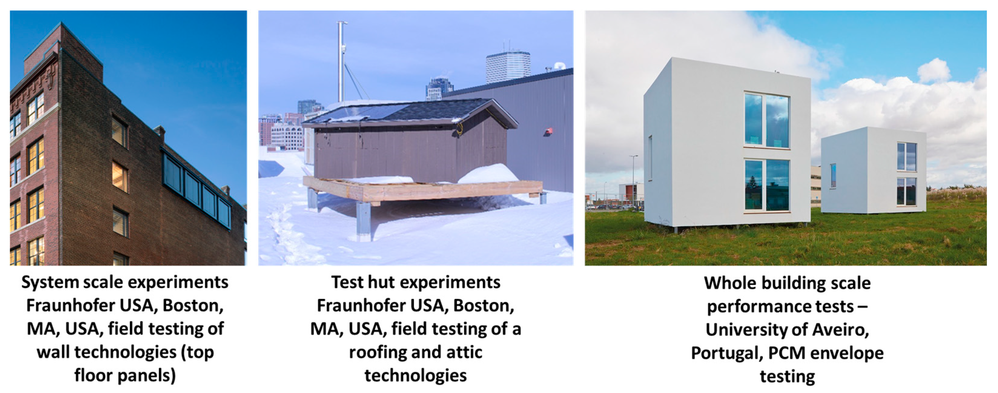
From another perspective, the development of numerical models and whole-building energy simulation tools, as well as the validation of these tools, are frequently important purposes for the conduct of full-scale field experiments. The development of whole-building energy codes, energy performance demonstrations, or long-term durability evaluations of PCM products may also involve long-term, full-scale field testing. As shown in
Figure 1, there are several modalities for performing full-scale field tests. There can be (i) system-scale experiments, like testing of elements of walls, roofs, geothermal heat exchangers, solar thermal components, etc.; (ii) test-hut experiments, where usually whole systems are tested as a part of a small building; and finally, (iii) whole-building-scale performance testing and technology demonstrations.
This paper discusses examples of both lab-scale testing and field experiments performed by the lead author’s research team to evaluate the thermal performance of PCM-enhanced building envelope technologies.
The focus of this paper is on the experimental performance analysis of panelized PCM technologies, which contain salt-hydrate-based PCMs. The application targets of these technologies are the improvement of internal building comfort, local temperature control, and the management of dynamic building thermal loads. This investigation was performed in the following three experimental formats:
- −
Laboratory material scale testing;
- −
Laboratory system scale testing;
- −
Field exposure analysis with the use of test huts—see
Figure 1. Fraunhofer USA test facilities in Boston, MA, USA, and University of Aveiro, Portugal test huts [
35].
This paper discusses thermal performance testing conducted on building envelope components containing inorganic PCMs. Compared to other geographic locations, lightweight construction methods used in North America are mostly based on lightweight materials with very little thermal mass (wood or light-gage steel framing). Wood- or steel-framed buildings can contain even up to 5 times less thermal mass than their stone or brick equivalents (high- or medium-density structural and envelope materials) [
36]. This absence of thermal mass combined with dynamic, climate-related temperature changes results in a low ability to control the building’s dynamic thermal response, which leads to large daily variations in indoor air temperatures, compromised internal thermal comfort, and increased space conditioning energy consumption. Numerous system-scale and whole-building demonstration projects worldwide have already demonstrated that adding PCM thermal mass to building envelopes and internal components can yield a noticeable rise in the building’s thermal storage potential and thus improve dynamic thermal load control, which can assist in improving the overall building’s energy performance [
21].
The high heat storage capability of PCMs represents a very appealing substitute for traditional building thermal mass, like, for example, stone, solid wood, adobe, masonry, or concrete. This is because of PCM’s low weight, which is combined with its high heat or cold storage density. Multiple types of PCMs are used in buildings, with service temperatures ranging from −5 °C (envelope winter temperatures) to +70 °C (roof maximum temperatures during the summertime). However, for most common internal wall and ceiling usage, the PCM’s service temperature should be aligned with human thermal comfort preferences (depending on PCM application, +16 °C to +35 °C). PCM products used in buildings are expected to store and release comparatively large amounts of energy every day during the entire building’s lifespan (at least 25 years). The commonly applied latent heat storage materials used in buildings are paraffins (organic), fatty acids (organic), and salt hydrates (inorganic) [
37,
38,
39]. Various combinations of eutectic PCMs can also be utilized in building applications [
38,
39,
40,
41,
42,
43]. They are compositions of two or more PCMs, where each of them melts and freezes congruently, forming a mixture of crystals. A large volume of research and commercial publications characterizing different types of PCMs exists today. For example, a list of 118 organic and inorganic PCM substances, organic and inorganic eutectics, fatty acids, and non-eutectic mixtures with potential for use in latent storage applications was developed by Zalba et al. [
40]. In another group of publications, Lane [
38,
41,
42,
43] classifies 210 organic, inorganic, and eutectic materials that undergo phase change without component separation (segregation) and are appropriate for use in buildings.
4. Materials and Methods
In this section, materials and commercial testing of the PCM for building applications have been discussed. Building systems, including the hut setup, thermal insulation, thermophysical properties of PCM composites, and PCM packaging and its specifications, have been discussed.
4.1. Thermophysical Properties of Analyzed Composites and Packaged Systems Containing PCMs
Two inorganic salt-hydrate-based PCMs based on calcium chloride hexahydrate (CaCl
2.6H
2O) were prepared and tested. In one of the formulations, sodium chloride (NaCl) and strontium chloride hexahydrate (SrCl
2.6H
2O) were used as stabilizers and nucleating agents, respectively [
44], whereas in the other sample, potassium nitrate (KNO
3) and potassium bromide (KBr) were used as stabilizers and strontium chloride hexahydrate (SrCl
2.6H
2O) as nucleating agents.
Panelized PCM products were also tested, where calcium chloride hexahydrate (CaCl
2.6H
2O) was modified with sodium chloride (NaCl) and strontium chloride hexahydrate (SrCl
2.6H
2O), which acted as a stabilizer and nucleating agent, respectively. This PCM was packaged into PVC sheets. This product is planned to be commercialized for use in residential and commercial ceilings, floors, and exterior walls.
Figure 2 show the commercial PCM panels used in this project (basic PVC panels and PCM panels laminated with reflective foil) and the test specimen (one square of the whole PVC panel) used for dynamic performance testing.
Table 1 lists the basic dimensions of the tile along with the mass of the PCM filled in it for both the eutectic formulations used for the testing.
In the second eutectic PCM formulation, potassium nitrate (KNO3) and potassium bromide (KBr) were added to calcium chloride hexahydrate (CaCl2.6H2O) to lower the melting temperature, and strontium chloride hexahydrate (SrCl2.6H2O) was added as a nucleating agent.
To analyze the thermophysical characteristics of PCMs used in commercial products, small test samples of the inorganic salt-hydrate-based PCMs based on calcium chloride hexahydrate (CaCl
2.6H
2O) were collected from the PVC panels (
Figure 2) and then tested in DSC. The DSC test parameters were the same for all samples. The weight of these samples was between 5 and 8 mg. The heating rate and cooling rate were 2 °C/min. The first PCM formulation, in addition to calcium chloride hexahydrate (CaCl
2.6H
2O), contained sodium chloride (NaCl) and strontium chloride hexahydrate (SrCl
2.6H
2O), which were used as stabilizers and nucleating agents, respectively. In the second formulation, potassium nitrate (KNO
3) and potassium bromide (KBr) were used as stabilizers, and strontium chloride as a nucleating agent.
4.2. Challenges with Differential Scanning Calorimeter (DSC) Testing of PCM Products
DSC results can be misleading in the case of non-uniform mixtures with, for example, thermal insulation or structural materials. DSC characterization presents an integral value of melting or solidification enthalpies, which are functions of temperature and do not include sensible heat. Furthermore, DSC testing is not useful in the system-scale analysis of PCM-based composites or arrays of PCM pouches, pockets, or containers, where 3-dimensional heat transfer effects and different sizes and shapes of PCM enclosures may impact the overall system thermal performance. Finally, DSC testing of small PCM samples may not be fully representative of a whole PCM product.
Key parameters that influence the results of DSC testing include heating and cooling rates, small sample sizes, and homogeneity. A high heating rate reduces temperature resolution during DSC testing, which leads to poor separation of phase transition peaks, and sometimes no peaks are observed. Broader energy peaks showing indistinct melting temperatures can be observed because of the larger temperature gradients associated with shorter time intervals. The cooling rate in DSC testing affects the crystallization behavior of a sample. A high rate of cooling may show “misleading” supercooling, where the delay in the crystal formation is unrealistically long and, consequently, the solidification temperature is lower than what can be observed using, for example, step DSC testing or by using significantly lower cooling rates [
41,
42]. Simply put, at high cooling rates, the PCM substance may not have enough time to initiate the local nucleation processes and crystals to start growing.
In addition, in DSC tests, the sample sizes are very small compared to the real PCM products’ sizes. This fact even further affects the occurrence of PCM supercooling. Furthermore, for non-homogenous PCM products, achieving sufficiently good sensitivity and high resolution in a single experiment is nearly impossible using DSC.
All the facts listed above justify the need for additional testing using either the T-history method, DHFMA testing, dynamic hit-box testing, or other types of system-scale thermal performance testing methods.
4.3. Dynamic Heat Flow Metter Apparatus (DHFMA) Testing of Insulation Blends, Composites, and Packaged Products Containing PCMs
DHFMA measurements can be utilized to determine the dynamic thermal characteristics of building components containing PCMs. Originally, the HFMAs were designed to perform steady-state thermal conductivity testing of materials. It follows the specifications of the ASTM C518-21 standard test method for steady-state thermal transmission properties by means of the heat flow meter apparatus (see ASTM [
32,
45]). Typically, HFMA contains two isothermal plates, which are equipped with at least one heat flux transducer per plate. The temperatures of isothermal plates are most often controlled by a combination of thermoelectric elements and heat exchangers connected to the water chiller. In general, the DHFMA testing procedure is similar to the DSC step method [
46,
47], but it also represents an upgrade of the previously developed rapid temperature ramp methodology [
25,
48]. The ramp method upgrades improved the test accuracy without any major modifications to the existing HFMA equipment and did not require any expensive hardware improvements. The DHFMA method is specifically useful for the performance analysis of composites or blends containing PCM and PCM products packed in the form of panels or boards.
In this work, a heat flow meter (Laser Comp. Fox 300 HFM from TA Instruments) was used to apply the DHFMA testing. The measured sample thickness and temperature difference between two HFMA plates are utilized to determine the thermal conductivity of a tested sample. The DHFMA test procedure requires that, at the start, both the top and bottom plates have the same temperature. This is different from conventional steady-state HFMA testing, where top and bottom plates have different temperatures to create a temperature difference across a tested sample. During the DHFMA measurement, the temperature is changed in a stepwise fashion, and the heat flow is measured isothermally. When both HFMA plates reach thermal equilibrium from one temperature set point to another, the heat flow absorbed by the test sample is computed (per sample area—J/m2). At this time, both the upper and lower HFMA plates stay at the same temperature to maintain temperature uniformity throughout the PCM and to allow the sample to reach equilibrium. The baseline heat absorbed by the instrument is subtracted from the total measured heat transferred across this sample. They are used to determine the actual amount of heat absorbed by the sample. The raw recorded HFMA signals, QUi and QLi, and their calibration factors, SU and SL, and time interval (t) are used in the calculations.
Heat flow meters give us two values: heat flow per square area (Δh
area, J/m
2) and specific heat (Cp, J/m
3K) based on Equations (1) and (2) from
Table 2. Volumetric enthalpy change (Δh
(volume), J/m
3) can be calculated by using Δh
(area) (Equation (1)), and the thickness of the sample and mass enthalpy change (Δh
(mass), J/kg) can be calculated by dividing the Δh
(volume). Equations (3) and (4) are used for calculating Δh
(volume) and Δh
(mass).
Table 2 shows all equations, variable definitions, and units used in calculating thermal properties from the HFMA outputs.
In this work, the results obtained from the DHFMA testing were compared with the DSC enthalpy test results.
4.4. Field Test Hut Testing of PCM Products
Panelized PCM building products were demonstrated on small test-scale timber frame buildings (2.44 × 3.05 × 2.44-m test huts). Test huts were constructed about 50-km east of Charlotte, NC, USA, in hot and humid East Coast climatic conditions. The field exposure experiment discussed in this paper and presented in
Figure 3 includes the attic with a dynamic thermal disconnect (DTD) system application, which contains two types of PCMs, two air cavities with reflective surfaces, and thermal insulation. Its performance is analyzed in comparison to the baseline no-PCM attic. More information on construction details and performance analysis of different DTD systems installed on walls and within attic structures can be found in earlier publications of the corresponding author [
49,
50]. As shown in
Figure 3, the longer sides of these test huts face southeast. In addition,
Figure 3 shows the construction details of both tested attics.
The DTD attic system is constructed of PCM panels, which are packaged into thermoformed PVC sheets. One side of the PCM panels has a reflective foil surface. Each of these panels comprises four squares that are about 8.8 mm thick (see
Figure 2). They contain CaCl
2.6H
2O-based PCMs. In the tested DTD attic design, reflected air cavities were used to reduce the radiative heat exchange between the top of the roof and the bottom of the attic. Furthermore, earlier works by the corresponding author have already demonstrated that this kind of thermal disconnect system, where PCM panels are used in conjunction with reflective air cavities, can significantly reduce the thermal load transferred through the attic and increase the delay time of the heat wave passing across the building structure [
50]. Two types of inorganic PCMs were used in this experiment: (i) PCM with a melting point of 32 °C (top layers in huts A and B), and (ii) PCM with a melting point of 28 °C (bottom layer in hut A and top of the ceiling layer in hut B)—see
Figure 3.
Schematics of the test attics, including the key materials’ placement, are depicted in
Figure 4 and
Figure 5.
The attic’s dynamic thermal performance characteristics are closely associated with the building’s internal thermal comfort. The performance of the DTD attic containing PCM was compared to the conventionally built no-PCM attic containing the same type and thickness of thermal insulation. A fragment of a wider-range analysis is presented here (to be discussed in a separate publication after the completion of the 2023 summer tests). For this performance analysis, we used three example days where
The external roof surface temperature was sufficient to melt both PCMs,
The external roof surface temperature was sufficient to melt only the lower melting point temperature of PCM, and
Neither of the used PCMs went through the phase transition.
After the test huts construction was completed in August 2022, the field exposure testing of PCM products was performed in Albemarle, NC, in the humid, cooling-dominated climate of the U.S. Southeast Coast. This paper presents the test results recorded at the end of summer 2022.
6. Discussion
As described in previous sections, three types of dynamic testing methods were used for experimental thermal performance analysis of inorganic PCM formulations and panelized products containing these PCMs. The goal of this testing was to compare the test results, highlight potential areas of result interpretation problems, and directly compare the thermal performance of the full-size roof assembly containing PCM products against the traditional lightweight no-PCM assembly. Calcium chloride hexahydrate (CaCl2.6H2O)-based PCM formulations were used in this work.
6.1. Laboratory Thermal Testing of PCM Formulations and PCM Products—Results Comparisons
The dynamic thermal performance characteristics of two PCM formulations and two panelized products containing these PCMs were analyzed. For this purpose, a series of thermal tests at material and system scales were performed in laboratory conditions. Results from the testing of these two groups were compared. At first, the thermal characteristics of two calcium chloride hexahydrate (CaCl2.6H2O)-based formulation samples were tested using DSC apparatus with heating and cooling rates of 2 °C/min and a temperature range of 5–48 °C. The melting for both PCM formulations took place at around 26 °C, with peak temperatures at 30–31 °C, respectively, for the first and second PCM. The measured melting enthalpies were 173 J/g and 170 J/g for the first and second PCMs, respectively.
Next, system-scale testing of two PCM products containing the same PCM formulations was conducted using the DHFMA testing method. Please notice that the second eutectic formulation underwent two melt-freeze cycles. The results were compared to the earlier DSC tests. For both types of measurements, the phase change temperature profiles and latent heat recorded during the melt cycles were similar. However, notable differences were observed for the PCM solidification processes and, consequently, in estimates of the supercooling. In DSC measurements, the solidification of the material started at around 6 °C and −2 °C, respectively, for the first and second PCM formulations. This indicated supercooling levels of about 20 °C and 28 °C. At the same time, the DHFMA testing showed negligible supercooling in both cases. Furthermore, in the case of the second eutectic formulation, the latent heat for the heating cycles was almost equal in both cycles; however, the heat released during the first cooling cycle was about 20 J/g smaller than the heat recorded during the second cycle. This indicates the potential instability of the formulation and a need for follow-on durability tests with a larger number of freeze-thaw cycles.
Observed differences in PCM solidification cycles can be linked to significantly smaller samples used during the DSC testing (5–8 mg) and, consequently, a greater probability of a deficit of nucleation sites. This may lead to a delay in the onset of the crystallization process. Furthermore, surface energy, in the case of small samples, can create a barrier that inhibits the formation of nuclei. Finally, during the DSC testing, the surface defects in the test pan can additionally affect the speed of nucleation [
51]. When combined with the cooling rate of 2 °C per minute, they can cause a notable delay in PCM crystallization. As a result, during DSC testing, a substantial supercooling of 20 °C and 28 °C was observed in both PCM formulations. Furthermore, the recorded latent heat for freezing can also be affected because of this “fictitious” supercooling. When the material is cooled below its melting point and still in the liquid phase, the measurements of the latent heat can be inaccurate (because of the unique physical characteristics when in the metastable state) [
50].
In the DHFM method, however, the sample size is larger than the DSC sample, and consequently, there are more nucleation sites available for the formation of nuclei. This allows for more intense crystal growth. That is why, in DHFMA testing, either no or negligible supercooling effects were observed.
The presented test results and comparisons between the DSC and DHFMA testing demonstrate that the DSC testing, performed with relatively small sizes of PCM samples, may sometimes show a “fictitious” supercooling effect, not reflecting the nucleation and subsequent crystal development processes in larger packaged PCM products. This difference in cooling cycle behavior highlights the need for verification of the DSC results with system-scale DHFMA testing in the case of real PCM products. This plays an important role in the testing of PCM products used in buildings, where the frequency of phase change processes is significantly lower than, for example, in heat sink electronic applications. To avoid any mistakes in performance assessments of composites and blends containing PCMs, as well as packaged PCM products, the ASTM C1784 DHFMA procedure should become obligatory before any conclusions can be derived regarding their supercooling behavior.
6.2. System-Scale Field Thermal Testing of PCM Products
In buildings, the most important dynamic characteristics of technologies containing PCMs are their phase transition enthalpies and their ability to shift the time of the thermal response to the peak solar and/or exterior temperature excitations. In this paper, we analyze the effect of the load-time shifting capability of the DTD attic containing two types of PCMs. The experiments were conducted in the warm and humid climate of North Carolina, USA, using two identical test huts covered with a single sloped roof, where the dynamic thermal performance of the DTD attic configuration, which utilizes flat panels containing PCM, was compared against the conventionally built no-PCM attic. Both attics contained the same type and thickness of conventional thermal insulation. The DTD attic was tested during the days when both PCMs were engaged in phase changes; only the lower-temperature PCM went through the phase changes, and neither of the PCMs were working because of low exterior temperatures.
The comparison of the recorded temperature data in both types of attics shows that the DTD attic, containing (i) two PCM panels (29 °C and 22 °C), (ii) two air layers with reflective surfaces, and (iii) a layer of thermal insulation, generates a 4.5 to 5.5-h time delay in transmitting the peak roof thermal load to the ceiling level. This delay time is about 3.0 to 4.0 h longer than in the case of a conventional attic using only thermal insulation. Surprisingly, it was found that for the DTD attic, the time delay was similar for all three temperature scenarios—regardless of associated phase transition effects. It was between 4.5 and 5.5 h, almost independent from the exterior roof and attic air temperatures, where either both PCMs were fully melted and solidified, only one went through the phase’s changes or neither one. Furthermore, the peak temperature drop across the attic assembly was similar in all three temperature scenarios, and it was between 30 °C and 32 °C (about 10 °C larger than in the conventional attic).
Finally, the DTD attic reduces the peak temperature by about 10 °C more than the conventional attic. This creates significantly lower temperature fluctuations on the interior/ceiling side of the DTD attic. It can also be observed that, during the early fall testing period, in the case of the DTD attic, the minimum nighttime ceiling temperature is about 8 °C to 10 °C higher than the outside rooftop temperature—see
Figure 13 and
Figure 14.
Please keep in mind that, during these experiments, the PCMs used in the DTD system were still working as conventional thermal masses. These PCMs utilized their sensible heat to reduce the maximum temperature and provide a time delay for the transmission of the peak thermal excitation. Our test-hut experiments demonstrated that thermal mass effects generated only by sensible heat are quite significant in the case of inorganic PCM products, and they should not be ignored.
For the sake of dynamic performance comparisons, it should be noted that the density of inorganic salt-hydrate-based PCMs is between 1.4 and 1.6 g/cm
3. The sensible heat storage capacity of two 9-mm-thick layers of inorganic PCM (used in the DTD attic) is equivalent to over three 10-mm-thick gypsum plaster boards (with a density of around 0.7 g/cm
3). So, even when PCM is not fully engaged in phase transitions, it still adds significant heat storage capacity to the building component where it is installed. The results presented in this paper align with the earlier research presented by Kośny et al. [
45], where the thermal performance of attics containing PCM products was compared to that of no-PCM attic systems. Both groups of technologies contained ventilated channels, reflective layers, and thermally massive components. In that research, no-PCM DTD attic designs using thermally massive components demonstrated comparable time delays to similar systems with added PCMs.
An additional consideration is that our test hut experiment started in the late summer of 2022. So, we had only small chances to test the DTD attic during the extreme mid-summer temperatures, with both types of PCMs being fully engaged in the phase transition. That is why, due to the limited number of high temperatures and full insolation days, additional testing will be performed during the summer of 2023 to learn more about PCM performance during the days, when both PCM can be fully melted during the day and solidified during the night. Furthermore, additional cycling testing will be performed to imitate below-freezing night temperatures. The goal is to eliminate the potential for PCM to disintegrate because of the freezing of the water.


 ,
, 


