Abstract
This study addresses the challenges and barriers associated with the implementation of circular economy principles in architectural design and construction practices. It highlights the fragmented knowledge and lack of a unified approach to circular design as a major obstacle hindering the adoption of circularity. The existing frameworks for assessing circularity, such as the Material Circularity Indicator (MCI) protocol and the Level(s) assessment protocol, are applied to two projects with a high degree of deconstruction to understand their applicability in the architectural design process and identify their limitations. The study emphasises the significance of considering structural connectivity and circularity strategies during the concept-design stage, advocating for the incorporation of circularity at various scales beyond the microscale of materials. Furthermore, it emphasises the need for early implementation of Design for Disassembly (DfD) strategies on circularity scoring to enable meaningful comparisons of alternative designs using circularity metrics. The findings reveal the variability of circularity indicators based on the hierarchy of disassembly and highlights an early-stage design approach to deconstruction strategies to achieve circularity in architectural design. Overall, this study upscales the significance of a comprehensive and integrated approach to circularity in architectural design practices.
1. Introduction
1.1. State of the Art and the Importance of Evaluating Circularity from the Concept-Design Stage
In the last few years, circular economy has reached unprecedented popularity among researchers and scientists. This rush for circularity (Figure 1) has also raised questions on how the architectural design method can contribute to the effective implementation of circular economy in the built environment [1].
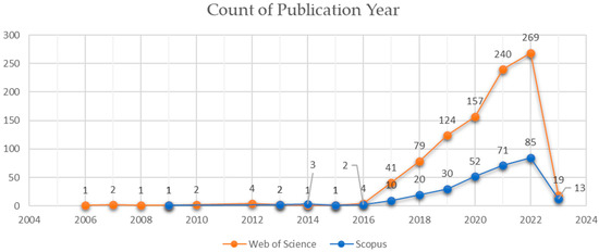
Figure 1.
Count of publications featuring the keywords “circular economy” and “architecture” on Scopus and Web of Science.
Fragmentation of knowledge and the lack of a unified circular design approach are among the obstacles to the acceptance and diffusion of circularity in professional practices [2]. The reasons can be sought in the fact that the circular economy (CE) is the catalyst for new ways of conceptualising architecture, such as thinking in terms of multiple life cycles [3,4], foreshadowing the reality of an alternative economy, promoting a deeper understanding of construction materials [3,4] and embracing a systemic vision over the use of resources and their life cycles [5,6,7]. Systems-oriented thinking has long been discussed in business literature [8] and design; however, little is known about how such approaches are adopted in architectural design and construction practice [1]. Charnley et al. noted that “designers have received little guidance on how these techniques should be implemented efficiently within an operational and substantially complex design process” [7] (p. 157).
Charef et al. explored the challenges and barriers to the implementation of circular economy in building design, noting that the early stages of the design process are critical for establishing the direction and scope of a building project and that a lack of guidance and support at this stage can limit the adoption of circular design practices [9]. A similar argument is supported by Çetin et al., who highlighted the need for a more holistic and integrated approach to circular design and proposed a new framework for it based on digital data processing [10].
Reaching similar conclusions, Osobajo et al. (2022), after delivering a thorough review of the state of the art of the circular economy in construction, including the application of circular principles to building design, concluded that there are limited investigations covering the impact of the circular economy on the design process in the construction industry [11].
This limitation is also evident from a literature review conducted on Scopus and Web of Science using the keywords “circular economy” and “architecture,” where a limited investigation into the relationship between the design process and circular economy was confirmed. The results, presented in Figure 2, indicate that there is no specific cluster related to “design,” suggesting that the most up-to-date literature lacks insight into the relationship between circular economy principles and the architectural design process.
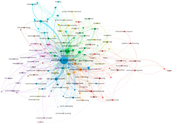
Figure 2.
Cluster analysis of publications from WOS (949) and Scopus (240) featuring the keywords “circular economy” and “architecture” using VOSviewer.
This indicates a tendency to treat circularity as a matter of sustainability and LCA rather than a matter of design [12]. The diagram in Figure 3 shows how the literature clustered in research fields are densely self-connected but present a low direct correlation with “circular economy” in favour of “life-cycle assessment” and “sustainability”. This mirrors what was already observed in the larger sample of publications. Design has a strong correlation with sustainability and a weak one with circular economy, indicating that circularity is often not addressed from a design process perspective. More importantly, no strong correlation was captured regarding the role of design and the indicators established to measure the circularity performance of buildings. This lack of correlation is the stepping-off point of this study.
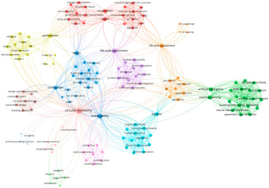
Figure 3.
Cluster analysis of publications with “circular economy” and “architectural design” as keywords.
The background of this study draws upon several publications, which have played an influential role in shaping the purpose and direction of our research. A list of these publications is provided in Table 1 for the readers’ ease. It is important to note that each publication cited in the References section contributed to the development of our study, and those highlighted in Table 1 specifically inspired the initial critical reflections on the research gaps and questions that led to the writing of this paper.

Table 1.
List of the most influential publications for the identification of the literature background of this study.
Moreover, the literature suggests how the indicators can be used as design tools, denouncing the lack of appropriate and consistent parameters and making it difficult to quantify and communicate the benefits of circular design strategies to stakeholders and clients [13]. As a consequence, researchers have started to put their effort into proposing new frameworks for circularity [12], recognising the importance of measuring the performances of buildings on a quantitative rather than qualitative basis. Nevertheless, these studies propose advancements in the application of circular design practices in architecture, introducing frameworks that sometimes add to the sophistication and complexity of the existing ones, with the disadvantage of creating further confusion for the designers in terms of practical implementation [1]. For instance, given the economic pressure that circularity puts on design labour and associated costs, the crucial challenge for designers is measuring and sharing the overall benefit of circular design practices with the stakeholders involved in the building process.
On these grounds, this study does not propose a new framework [14] for evaluating circularity in architecture but operates a critical reflection on the existing circularity principles and evaluation protocols to develop an understanding of how circularity indicators (CI) can be “fit-for-purpose” decision-making tools at the concept-design stage. This specific moment of the design process has, in fact, been neglected in the literature, creating a missed opportunity to explore the application of existing, and formally coherent, CI at the very inception of the architectural idea of a building and use circularity and circularity metrics as a means to shape the architecture of the future from the cradle.
1.2. Measuring Circularity in Current Standards
1.2.1. The Material Circularity Indicator (MCI) Protocol by the Ellen McArthur Foundation
Governments and international institutions are developing and promoting protocols for evaluating circularity indicators as part of larger sustainability evaluation systems. As an advocate for the diffusion of circular economy, the Ellen MacArthur Foundation is currently leading the advancement in what can be called “circularity assessment”. The foundation developed a protocol to assess the circularity for products and businesses called the Material Circularity Indicator (MCI) as part of a larger Circular Indicators Project. The MCI protocol is a material-based assessment method. The circular performance is expressed by the main MCI equation [15] in cl.2.1.2.5 as:
When the value of 1 is used, it indicates perfect circularity, meaning that the product’s mass is entirely composed of recycled or reused materials; LFI is the Linear Flow Index, indicating the percentage of material(s) procured according to a linear system (e.g., harvested from virgin sources and ending as unrecoverable waste); and F(X) is the Utility Factor. This last function is a measurement of the efficiency of the product (the word “product” must be intended in its largest meaning, which includes buildings and any design in general), which is object of the evaluation, in terms of the lifespan of the product (L) in comparison with the industry average lifespan of similar products (Lav) and in terms of the intensity of use of the product (U) compared to the industry average intensity of use of similar products (Uav). The equation for calculating X is in cl. 2.1.2.4 as:
The first part of Equation (2) can be read as a measure of the exploitation of the product over multiple life cycles. Let the expected lifespan (L) of the designed building be 100 years. If the average lifespan (Lav) of similar buildings is 50 years, then the ratio L/Lav yields a value of 2. The last part of the Equation (2) is a measure of the exploitation of the product on shorter timeframes, perhaps daily, hourly, and so on [15]. Assuming that the designed building is such that it is used 24 h (U = 24) and that similar buildings are used, on average, 8 h per day (Uav = 8), the ratio U/Uav would return a value of 3. The resulting value of X would then be 6.
In accordance with cl. 2.1.2.5, the Utility Factor is expressed as:
Therefore, for a value of X = 6 the value of F(X) would be 0.15. The higher the Utility function, the lower the impact of the LFI in the overall MCI scoring.
Furthermore, it is worth highlighting that, for a building with the same utility as the industry average, since X = 1, the Utility Factor is 0.9. The detailed implications of this on the MCI scoring can be found in cl. 2.1.2.5 and in Appendix C of the MCI guidelines [15].
The calculation of the MCI is strictly related to the calculation of the LFI, for which a detailed knowledge of the Bill of Quantities (BoQ) and material flows is required. For the latter, detailed knowledge of the proportion between recycled, reused, or virgin materials must be assessed or assumed at modules A1-3 and C1-4 and D [16] in the lifecycle of the building for realistic results.
1.2.2. The Level(s) Assessment Protocol by the European Commission
The European Commission responded to the need for sustainability metrics to promote sustainable growth of the construction sector [17] by issuing the Level(s) assessment protocol [18] aiming at setting a common framework for the assessment of sustainability [19] across the stages of a building lifecycle (i.e., conceptual, detailed design, construction, and as-built or in-use stage). The framework identifies specific performance indicators, looking at environmental performance as well as health and comfort, life-cycle cost, and potential future risks associated with the efficient use of energy and resources.
Among those, the performance indicator related to circularity is identified as Level(s) indicator 2.4: Design for Deconstruction [20]. This indicator is to be regarded as a circularity indicator, similarly to the MCI. One can identify additional similarities between the Level(s) framework and another indicator by noting that both require a thorough understanding of the Bill of Quantities (BoQ) as a necessary step for computing the circularity score. Once the bill of materials is known, the evaluator is asked to identify the circularity strategies suggested in cl. L.1.4 and classified in terms of:
- Ease of disassembly;
- Ease of reuse;
- Ease of recycling.
For each item of the BoQ, the evaluator shall determine a circularity coefficient based on the weight (kg) and cost (EUR) of each building item and the adopted disassembly strategies. These end-of-life strategies relate to the waste hierarchy set out in the EU Waste Framework Directive [21] and are expressed in terms of circularity coefficients:
- Direct reuse (circularity coefficient = 1.00);
- Preparing for reuse (circularity coefficient = 0.90);
- Pure stream recycling (circularity coefficient = 0.75);
- Mixed-stream recycling (circularity coefficient = 0.50);
- Material recovery (circularity coefficient = 0.25);
- Energy recovery (circularity coefficient = 0.15);
- Inert or non-hazardous landfill (circularity coefficient = 0.01);
- Hazardous waste disposal (circularity coefficient = 0.00).
As a direct example, in Figure 4 it can be seen how the mass and the cost of each material entry are classified according to their location within the building and a “Circularity: best practical outcome” is assigned to the material to determine the circularity coefficient (from 0 to 1). The mass and the cost of the material entry are scaled by the applied circularity factor and then the overall circularity score is calculated in terms of mass and cost. This circularity score is the weighted average of the partial contribution given by all entries expressed in the form of:
where CFk is the circularity factor, Mk is the mass, and Ck the cost associated with each material entry.
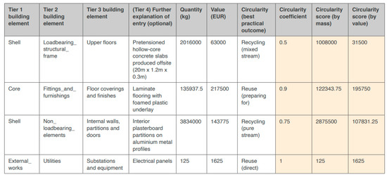
Figure 4.
Abstract from Case Study Macro-objective 2: Resource efficient and circular material life cycles [19] showing a typical check sheet for the calculation of the circularity indicator LC2.4.
Despite the extent of the material flow data and background information required and to be processed to complete the circularity assessment for compound and multi-material products, like in the case of a building, the outcome of this process amounts to a single value of circularity score by mass or by value. It may be argued that to include a circularity score in standard design outputs requires additional fees and time whose significance may not be straightforward to communicate to stakeholders who are not directly involved and knowledgeable on the topic, let alone the clients who often lack awareness and/or willingness to engage with the circular economy [22]. The underlying principle behind Level(s) L 2.4 is assessing circularity downstream of the design process. In fact, looking at the definition of the scoring, no allowance is made to consider whether the materials employed are sourced from virgin sources or come from recycling or reuse loops already. It must be noted that other indicators are included in Level(s) with a specific focus on material waste management and procurement. The most relevant to this study is Level(s) indicator 2.2: Construction and Demolition waste and materials. This indicator takes into account the origin of construction materials and sets guidelines and assessment methods for a circular sourcing and management of construction materials. Indicator L2.2 is independent of L2.4 outlining key thresholds for the fractions of reused, recycled, virgin, and landfill materials to be respected in order to evaluate the sustainability of the building and offering metrics to quantify the achieved level of sustainability. However, indicators L2.2 and L2.4 can be related in terms of the general waste strategy adopted for the design of the building. Therefore, we can highlight how the main difference between the MCI scoring and the L2.4 scoring is that the latter may be read in conjunction with the L2.2 indicator in order to be more comprehensive of the effective circularity of the building or “product” assessed. On the other hand, indicator L2.4 allows circularity factors to be input to each material entry, providing a simplified and faster approach than the one outlined in MCI, which entails a detailed knowledge of material flows in order to calculate the LFI [23].
Both of the aforementioned methods to measure circularity—MCI and Level(s) L2.4—tend to be highly based on the BoQ, and therefore have a strong dependency on the capacity of the materials to enter a circular flow. The immediate consequence of this is that materials with high reuse or recycling potential (for instance, timber) may take the lead in terms of circularity scoring, but in the complex organism of a building, the interfaces between the different materials and the assembly of parts and elements may have a direct impact on the circularity regardless of the material adopted.
When reflecting on the complexity of any design and building process, these circular parameters come with limitations since they focus mainly on the micro-level of the material [23,24].
Moreover, concepts such as Building as Material Banks (BAMB) and Design for Disassembly (DfD) are driving transformative changes in the realm of building fabric connectivity. This strategic approach serves as the foundation for facilitating the circular flow of materials, regardless of their specific composition [25]. Connections play a critical role as pivotal interfaces, meticulously integrating building elements to enable the seamless transfer of both static and dynamic loads throughout the entire structure. The reversibility of these connections correlates directly with the building’s inherent capacity to embrace circularity [26,27,28,29,30]. Within the Level(s) framework, the significance of connectivity in achieving circularity is quantified by the circularity factor (CF), whereas a similar factor is not present explicitly in MCI. Reversible connections are assigned a CF of 1, accounting for their substantial contribution to circularity, whereas irreversible connections are designated a CF of 0, underscoring their inherent limitations in achieving circularity.
Intermediate values of CF represent mixed situations with varying degrees of circularity due to re-manufacturing processes or recycling processes. The circularity factor is, in reality, determined by broader considerations, of which the system of connections adopted is just a small part. At page 23 of Levels(s) LC2.4 a reference is made to the BAMB and DfD [20] although stated as optional design strategies for inclusion in the assessment of circularity. It can be argued that DfD constitutes the basis for an effective implementation of circularity [31]; therefore, the scoring system should make allowance to assess the impact of the application of the three main principles of DfD (structure adaptability, modularity of elements, physical interchangeability of parts) rather than suggesting optional adoption. In the MCI method, the varying degree of reversibility of the connections is indirectly included when the assessor calculates the proportions of reused, recycled, or landfill waste within the LFI.
Given the inherent nature of the protocols themselves, fully unravelling the contribution of connectivity may prove challenging. However, there is an opportunity to research how different disassembly strategies can provide a valuable foundation for informed decision-making during the concept-design stage, going beyond solely considering material selection [23] and recognising the DfD hierarchical principles from the early inception of the architectural concept.
Accounting for the broader perspective of hierarchical connectivity alongside material selection constitutes an innovative approach towards circularity and the implementation of circularity metrics in the design decision process, ensuring that the concept-design stage encompasses a holistic evaluation in promoting circularity and linking the DfD strategies with waste hierarchies [1,25,26,27,29,32,33,34].
2. Materials and Methods
The contribution is articulated in three main stages: (i) a review of the existing literature and gaps, (ii) identification of the selection criteria for the case study, and (iii) analysis, comparison, and interpretation of circularity metrics results against the framing idea of the contribution and future advances in the field.
For the literature review, an algorithmic correlation strength analysis [35] was employed to analyse a total of 949 publications from Web of Science and 290 publications from Scopus to establish the correlation between keywords and gain an overview of how the literature incorporates the circular economy into architectural design and its multiple aspects. These publications were sought using “circular economy” and “architectural design” as keywords and were produced between 2006 and early 2023. The correlation was deemed significant if the keywords occurred a minimum of five times across the publications analysed.
A further refinement was carried out by filtering the publications that included the words “circular economy” and “architectural design” or “construction”. The papers resulting from this narrowing of the search were then analysed using the same algorithmic tool [35] to investigate correlations.
2.1. Selection and Description of the Case Studies
The case studies were selected using the criteria reported in Table 2.
Table 2.
Criteria of the selection of the case studies.
Based on those criteria, this study considers two examples of modular buildings designed with alternative DfD strategies as a result of two projects on emergency relief dwellings funded by the Italian region of Veneto in 2019 and 2021. The relevance of those projects to this contribution is strengthened by the fact that both rely on structural timber as the main material for the structure and the envelope, thus reducing the dependency of the circularity scoring on the material itself: Comparing two buildings with the same assortment of materials heightens the influence of the connectivity strategy on the overall circularity scoring and mitigates the variable of the nature of the material from the equations. Details on the case studies are given in the following sections.
2.1.1. Case Study A (CSA)
- Name of the project
- Study of innovative temporary wooden housing units for the shelter and accommodation of elderly people in case of functional redevelopment of buildings used as retirement homes.
- Design completion
- 2019
- Sector
- Healthcare and Assistance
- Purpose
The fundamental criterion of the project was the exploration of the reusability of the module and maximisation of the reversibility of the structural connections adopted. On an operative and detailed level this project also employed consultations with key contractors in the timber construction industry to identify suitable connectivity strategies. The rationale behind it was to find innovation in the alternative use of existing methods of joinery in an innovative way and maximise one of the four criteria of the circular economy: “reuse” [36].
- Collaborators
- Università Iuav di Venezia, Italy; University of Kent, UK; Bozza S.r.l., Italy; GreenTech Italy, Italy; Consorzio Progetto Legno Veneto, Italy
- Key Circular Aspects
- The key design aspects were modularity, flexibility, and adaptability of the emergency units to different sites, layouts, and conditions. The structural design was carried out in accordance with the criteria of spatial adaptability, structure modularity, and physical interchangeability, better known as DfD [28,37,38].
- Structural Detailing/Design Approach
The project was characterised by a strong focus on buildability, and it was undertaken in accordance with the Italian technical standards for construction (D.M. 17 January 2018), considering the installation of the module on the entire territory of the region of Veneto at altitudes not above 1600 m a.s.l. The structural detailing was carried out according to the aforementioned standards and other national non-contradictory complementary instructions (NCCI) CNR-DT 206/2007 issued by the Italian national council for research (CNR) and finite element simulations.
The modular unit constitutes of solid wood panels in CLT and framed panels for vertical partitions and floors, respectively. The roofing system is framed with structural elements in laminated wood and stiffening plates made with OSB panels (Figure 5). The design team focused on part interchangeability as the main strategy for reuse, thus concentrating on the connection interface between the single parts rather than developing solutions for larger elements or assemblies. The design strategy of the connections is such that it enables the building to undergo several cycles of assembly and disassembly over a lifespan of 50 years or more.
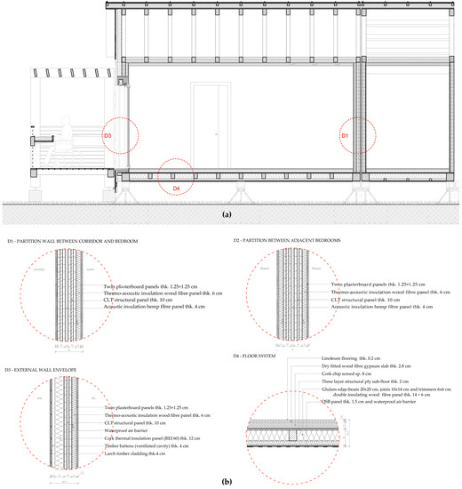
Figure 5.
Typical longitudinal cross-section of the modular unit (a) and envelope stratigraphies (b) for case study A. Drawn by Francesca Camerin; translated by the authors.
Typically, the modular unit is designed to be mounted and dismounted at least five times over a period of 50 years to maximise its use as a temporary dwelling. Upon inspection, after the 50-year time frame, further use for the module or its parts is also made possible by the reversibility of most connections. These are, in fact, based on the use of metal inserts (metal dowels with internal and external threads) bonded externally to the timber elements by friction (screwed), to which threaded rods are internally fixed to allow the transfer of the forces to steel plates bolted in turn to other threaded bars connected to adjacent timber or steel elements, as shown in Figure 6.
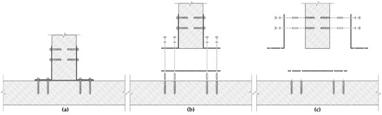
Figure 6.
Typical hybrid steel/timber connection mediated by the use of inserts and threaded bars. This system ensures full reversibility of the connection over multiple life cycles and according to the disassembly sequence (a–c). Drawn by the authors.
The designers and contractors took into account the reduction of the number of connections, minimising the interfaces and reducing the workings of the wooden elements as the main key performance indicators. In fact, most of the connections were developed using the technology of metal inserts and threaded soldier bolts that is nowadays common in the joinery of furniture but not so common in the structural timber industry. The main advantage of this technology stands in the complete reversibility of the connection and non-destructive deconstruction of the structure. The transmission of the loads is mediated by elements such as metal flanges, threaded soldier bars, and nuts, manageable as common bolted steel connections (see Figure 6).
The project also highlighted how structural reversibility determines the complete circularity of the product, and, from a practical point of view, the reversibility of the wooden connections can be effectively implemented through the design of hybrid steel–wood joints. This strategy has a direct impact on the extension of the service life of the wooden parts and allows the utility of the material to be maximised, minimising the loss of material at each assembly/disassembly stage, which would generate unusable waste. This way, the design allows for structural reconfiguration and repurposing as well as part interchangeability, in accordance with the principle of “building as a bank of material”. The load-transfer flanges are kept in a simple and regular shape in order to be made readily available for reuse or to be recycled. The inserts are irreversibly bonded to the timber parts, meaning that separating them from timber would cause irreversible damage of the surrounding volume of material, which would need preparation for reuse. Where the use of inserts was not possible due to lack of space, screwed or stapled/nailed connections were used. This is particularly evident at the heel of the roof truss element between the principal rafters and the bottom chord and between the OSB panels and the timber frame system of the roof and the floor elements. Everywhere else, reversible hybrid connections were used [38]. The foundations of the building were carefully designed to adhere to the principles of reversibility (Design for Disassembly, DfD) and minimum soil occupancy. This was achieved by incorporating prefabricated concrete plinths into the foundation system. These plinths were specifically designed to allow for their reuse in future life cycles without the need for repair or modification. By implementing such reversible foundation elements, the building not only promotes circularity but also minimises the disturbance to the soil and reduces the environmental impact associated with traditional foundation construction methods (for the homogeneity of the material, the absence of irreversible connections, and intrinsic durability, the foundations were excluded by the BoQ and calculation of the CI since their contribution did not offer significant insight into highlighting the impact of connectivity on the CI calculation. Moreover, the foundation systems of the two case studies are identical and based on exactly the same principles, so there is no substantial comparison that can be done on this matter). Strategically, this design was developed with a focus on the interchangeability of parts, elements, and assemblies and a lesser focus on the separability of raw materials at the end-of-life stage.
A LCA assessment on the modular unit by Palumbo et al. [37] showed how the extensive application of reversibility in this design resulted in 89% of the materials being reused or reusable at end-of-life without undergoing transformations. However, deterioration of the material mechanical properties and reworkings due to some irreversible connections amounted to a 4% waste production (due to nails, staples, and screws), and 7% being transformed into alternative forms and made available for other production cycles. Overall, 96% of the material was reported as not destined for landfill, reducing the impact of disposal at end-of-life [37].
2.1.2. Case Study B (CSB)
- Name of the project
- High Efficiency Emergency Living Prototypes Veneto (H.E.L.P. Veneto)—Sustainable adaptive residences for temporary living in environmental emergencies.
- Design completion
- 2021
- Sector
- Residential for disaster relief
- Purpose
- The H.E.L.P. modular unit can be seen in Figure 7. Designed as a modular emergency dwelling for temporary residential use, it allows for flexibility and adaptability of the interior spaces according to the needs of the occupants. The module also features an envelope that can be adapted in accordance with thermo-hygrometric needs at the altitude of construction. The adaptability of the envelope can be actioned by substituting the external layers with other layers of appropriate performance.
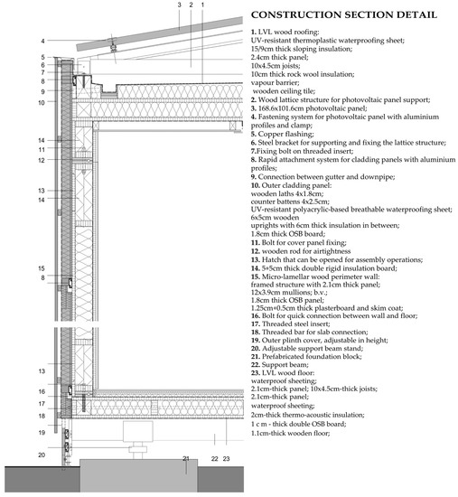 Figure 7. Section showing a typical construction section of the modular unit H.E.L.P. Veneto. drawing by Francesco Pozzobon; translation by Francesco Incelli.
 - Collaborators
- Università Iuav di Venezia, Italy; University of Padua, Italy; University of Udine, Italy.
- Key Circular Aspects
- The key strategy behind both features of spatial and performance flexibility is an extensive implementation of the DfD principles [28] at the different scales of parts, elements, and assemblies. In detail, the modular units of H.E.L.P. were designed to privilege the physical interchangeability of the structural elements, ensuring their easy disassembly, even for repeated life cycles, using hybrid wood–steel connections [26,27,29,38,39] with a high degree of disassembly.
- Structural Detailing/Design Approach
The assemblies, i.e., walls, roofs, etc., are connected by means of pressure joints or clamped joints for increased reconfigurability of the structure and of the modular unit itself. These are made of standardised timber frame panels with insulated cavity bundles to form the back wall upon which the insulated timber envelope can be clipped by means of clasps and undercut anchors. Connections between the large assemblies of the modular unit are made by compression joints with pre-tensioned threaded bars to ensure tightness at the interface.
By doing so, the design team engineered a modular unit (or assembly) that can be broken down into further modular elements (structural systems) and parts that are easy to transport, assemble, and deconstruct. Internally, each element type can be connected using common joinery, including nails, staples, or screws: This is the case for the panels forming the walls, roof, and floor systems, where the studs and joists and the OSB panels (parts) are nailed and stapled together for ease of construction. However, the mutual connection between the systems is reversible (inserts/soldiers or post-tensioned contact joint). The foundations are based on the exact same principles as CSA and differ slightly in terms of dimensions (similarly to CSA, the foundations of CSB were not included in the assessment. For their homogeneity of material, the absence of irreversible connections and intrinsic durability, the foundations have been excluded by the BoQ and calculation of CI since their contribution did not offer significant insight in highlighting the impact of connectivity on the CI calculation. Moreover, the foundation system of the two case studies are identical and based on exactly the same principles so there is no substantial comparison that can be done on this matter). The identification of valid and shared solutions not only by the designers but also by the whole construction supply chain generated an opportunity for the involvement of relevant stakeholders within the design process. Decision-makers and approval authorities on the matter of emergency (Veneto region and Italian Civil Defence officers) were consulted and asked to judge and discuss solutions with the designers and other stakeholders from the timber supply chain, interior designers, transportation providers, and suppliers of domestic equipment to support the production and construction of the H.E.L.P. module and tackle criticalities in advance. The involvement of stakeholders in the design process led to implementation of the suggestions by Mulhall et al. for a building with a positive impact [40]. Some of the H.E.L.P. structural connectivity solutions were also based on the use of hybrid steel-to-timber connections developed during previous projects (see CSA) through collaboration with stakeholders belonging to the timber construction and emergency supply chain in the Italian region of Veneto [39]. Similarly to CSA, CSB implements DfD principles at the assembly and system levels, meaning that the main design effort was put into devising reversible solutions at these scales of the building fabric by applying hybrid connections with a high level of disassembly between assemblies and systems only, resorting to the use of common methods for joining the parts and the materials together. In fact, one can notice, for instance, in the floor system, that the latter is detailed (Figure 7) as a standard timber frame floor system, with an exception made for the pressure joint at the ends of it, which is used to connect the floor to the wall element (in this paper, the word “element” is used as a synonym of “system” in accordance with the terminology used in Level(s)).
2.2. Methodology and Assumptions for the Comparative Evaluation of Circularity
The methodology followed for this study is articulated in several phases. In the first phase, the construction detailing and the deconstruction scenarios for both cases A and B are analysed in order to identify the following:
- Type and location of the connections used;
- Accessibility of the connections.
This analysis is to identify the actual reversibility of the building and the expected damage arising from the operations of deconstruction. Furthermore, through the construction details and the deconstruction scenarios, decided at the design stage, the authors can define the disassembly hierarchies. In fact, for each case study the circularity assessment is performed on a functional unit. With “functional unit,” the authors intend to identify the minimum number of assemblies required to install a fully operational emergency module.
For CSA and CSB, the functional unit corresponds to the number of assemblies related to one room, which are 26 m2 and 34 m2, respectively, and bathrooms. A layout with bundled arrangements of multiple functional units will not be considered inasmuch as the modularity of the buildings ensures that any evaluation, in the terms of this study, is not influenced by the number of modules considered, but it can be scaled down or up to the single functional unit, given that the circularity indicator is expressed as a percentage of the total mass and cost of the building.
In the second phase, detailed BOQs are calculated for both CSA and B functional units and the quantities are sorted and classified by belonging to a certain material (i.e., timber, steel etc.), part (i.e., beam, columns, or panel items), element (i.e., wall, floor, roof systems), or assembly in order to sort the information at the different levels of the hierarchy of disassembly. The assembly can be a large portion of the functional units made by the integral connection of elements or it can be the entire functional unit. At each disassembly level, the authors determined the expected entity of irreversible damage based on the type of connections used as well as the required deconstruction scenario.
In the third phase, a circularity indicator is calculated for each hierarchy level (i.e., material, parts, elements, assemblies) using the standardised protocols (MCI and Level(s)2.4). A separate set of results is produced for CSA and CSB and each set presents four circularity scores, as many as the hierarchy levels considered.
Because the identification of material flows is strictly bound to the knowledge of the site-specific procurement of materials, waste management, the reuse and recycling supply chain, and stakeholders’ engagement, assumptions are made to mitigate the effect of those variables on the circularity scoring. These assumptions are different for the MCI and Levels protocols as a consequence of the differences discussed in Section 1.2.1 and Section 1.2.2.
With regards to the MCI, a detailed calculation of the LFI is undertaken, entailing calculations of the circularity at the procurement (upstream) and deconstruction (downstream) stages. The assumptions made on the procurement of materials and virgin feedstock are based on the 50:50 principle outlined in the MCI guidelines [15] considering, in the lack of better information, 50% of the materials sourced from virgin feedstock and 50% sourced from recycled or reused materials. In the end-of-life scenario, set to happen 50 years after the first construction, it is assumed that the efficiency of recycling in 50 years’ time will improve compared to the efficiency of recycling to produce feedstock at the present time; hence, the recycling efficiency is set to 0.5 at the procurement stage and 0.7 at the end-of-life stage.
With regards to Level(s)2.4, the identification of the circularity factor is carried out in accordance with the hierarchy of waste [41] and on evaluation of the circularity best practice, as suggested by the protocol itself [20]. The effect produced by each connection type adopted in this study is summarised in Table 3. The table relates the type of bond imparted to the connected interfaces and the resulting reversibility expressed in terms of the circularity coefficient (used in Level(s)) and the fraction of material reuse (used in MCI).
Table 3.
Connection types and effect on the connected materials, parts, and systems.
For both protocols, only one life cycle (50 years) is taken into account, assuming that the proportion between reuse, recycle, and landfill stays steady at each life cycle. In the absence of detailed calculation about deterioration or decay [42] of some material, a 40:30:30 approach is used: 40% of the material is recycled, 30% is reused, and 30% is landfilled or decayed. This approach aims to set a conservative assumption on the efficiency of reuse and recycling of materials with no environmental performance declarations (EPDs) and literature available. The required material to restore any loss due to damage is not included in the BoQ of the current life cycle because it would be pertinent to the BoQ of the subsequent one. Since the MCI protocol requires a quantitative definition of the utility function of the object of the assessment, other assumptions have been made on the utility and lifespan ratios [15] (p.29) at each hierarchy of disassembly at the end-of-life stage. For materials (parts, elements, and assemblies) that are separated and intended to be reused as feedstock, a utility value of 1 was assigned (U = 1). Additionally, a lifespan value (L) is considered, which aligns with the average lifespan of similar materials in the industry. In the case of explicit reuse, the lifespan (L) is increased against the average for similar products in order to account for an end-of life-scenario where the parts, elements, or assemblies, and more rarely materials, are fed into a new life cycle. It was deemed reasonable that a lifespan increase of 25% to 50% above the average should be applied to reused elements [43,44]. As an example, let us consider a rafter equipped with hybrid reversible connections. If at the end-of-life the decision is to feed it into a recycling loop, then its utilisation is the same as a rafter featuring irreversible connections. On the contrary, if the design and disassembly strategies are such that the rafter is destined to be reused, then the utilisation is at least twice as much a rafter dismissed at the end-of-life stage. Regarding the lifespan, it is not straightforward to predict how weathering is going to affect the properties of the reused element; therefore, it is conservatively assumed that for all elements within the thermal and water line a factor of 1.5 is applied to the actual lifespan, whereas a factor of 1.25 is applied to the lifespan of elements outside the water and thermal line to allow for decay of the material due to weathering, thermal stresses, or damage from moisture [45,46].
2.3. Evaluation of Circularity Based on the Structural Connectivity and Disassembly Hierarchy
Clarifications should be made for the methodology applied in the third phase described in Section 2.3. At this stage, the focus is on determining the impact of the connectivity strategy and the variation of the circularity indicator at each level of the disassembly hierarchy. For each item at each hierarchy level, the connections with the surrounding objects are listed and categorised in terms or reversibility and associated waste hierarchy (see Table 3). The procedure adopted starts with identifying the assemblies and categorising each element contained into the assembly itself. In the following steps, the process is repeated through a breakdown of the assembly into elements and identification of the parts included in each one. This process of surgery ends with the breakdown of the parts into their constituent materials.
Preliminarily, a calculation of the percentage of reused mass is assessed as a benchmark to compare with the results obtained through MCI and Level(s). This calculation is to quantify the reused mass over the total mass of the item considered for each hierarchy according to Equation (6):
where M0 is the total mass before any workings are operated on the item, MRc is the recycled mass of the item at the end-of-life stage, and MLf is the mass that is landfilled or irreversibly damaged. Let M be the mass of a virgin CLT panel. When screws are used on it to operate any kind of connection, a volume of timber correspondent to the volume of the screw is transformed into irreversible waste, generating MLf, whereas the mass of the screws, which can be entirely recycled, contributes to the value of MRc. The total mass of the system CLT panel/screws is therefore M0, and Equation (6) can be used to calculate the %reuse. This method is a quick and approximate procedure scalable to the relevant hierarchy.
A schematic representation of the disassembly hierarchy is shown in Figure 8.
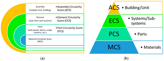
Figure 8.
Diagram of the disassembly hierarchy (a) and scoring (b) proposed for this study and based on the disassembly hierarchy outlined in Level(s) LC2.4.
In this study, four types of circularity scores are returned. They correspond to the four levels of hierarchy described earlier and shown in Figure 8a. The validity of this approach is entangled with the knowledge of the end-of-life scenarios associated with each level and the end-of-life target defined as part of the design goals established at the concept stage. Figure 8b shows how the circularity scoring follows the hierarchy of disassembly in an attempt to take into account the reuse target established at the concept-design stage: If the target is reuse of materials, then the relevant score to be considered is the MCS; if the target is reuse of elements, then the ECS overtakes it, and so on. In the methodology adopted, the scoring is calculated at all levels with no priority of one target of reuse on the grounds of outlining a flexible and adaptable approach that is not bound to a specific end-of-life scenario.
The following circularity scoring are calculated:
- Assembly-level Circularity Score (ACS): measuring the circularity associated with the end-of-life strategy of the assembly;
- Elements-level Circularity Score (ECS): measuring the circularity associated with the end-of-life strategy of each element or system;
- Parts-level Circularity Score (PCS): measuring the circularity associated with the end-of-life strategy of each part;
- Materials-level Circularity Score (MCS): measuring the circularity associated with the procurement and end-of-life strategy of each material.
3. Results
3.1. Analysis of the Construction Details
3.1.1. Case Study A (CSA)
The 26 m2 modular housing unit of CSA was achieved by joining five main sub-assemblies: two half c-shaped shells comprising the floor and wall systems and two single-pitched modules arranged to form a double-pitched roof for the main rooms. An additional flat roof system was provided for the lavatories housed in a w-shaped prefabricated shell sub-assembly. It is possible to discretise the analysis of the assemblies by identifying eight different elements corresponding to five different wall systems, two roof systems, and a single floor system, visible in Figure 9a.
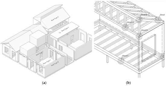
Figure 9.
Identification of standardised elements in CSA for the purpose of this study (a) and location of the critical connection points between vertical and horizontal closures (b). Drawn by the authors.
The CLT wall elements were designed with traditional nails and screws to bond the layers and the façade was similarly fixed to the backwall by means of screwed connections. Moreover, staples were employed to fix the OSB panels to the timber frame, as can be noticed in the floor system and the pitched roof element. However, the frame of the latter features screwed connections at the heel and hybrid steel connections with soldier threaded bars and inserts at the apex and bottom chord, where the posts meet with the ridge beam and the tee beam. Fully reversible connectivity was ensured at the interface between each system, meaning that wall-to wall, wall-to-roof (Figure 10c), and wall-to-floor (Figure 10b) connection was devised though the use of inserts and soldier threaded bars. This strategy can be also seen within the same floor element, where the main joists are connected to the edge beam reversibly (Figure 10a).
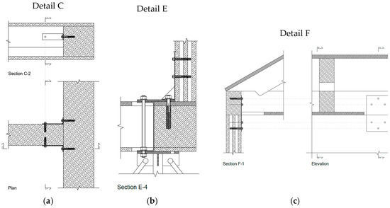
Figure 10.
Example of the use of the hybrid steel–timber connection system based on inserts and soldiers within the main joists of the floor element (a), between the floor system and wall parts (b), and between the wall-to-roof connection (c). Drawn by the authors.
The continuity of the envelope was achieved with pressure joints and lip gaskets in labyrinth joints. The internal finishes, primarily made of plasterboards and linoleum coating, were irreversibly bonded to each other and to the internal OSB panels and were prefabricated with each sub-assembly. The bathroom units were designed to be completely prefabricated and reused, but they were not included in the assessment of circularity in this study.
3.1.2. Case Study B (CSB)
The modular unit of CSB consists of eight types of elements with different openings, as shown in Figure 11c, arranged in a collection of 11 to form a 33 m2 housing unit over raised foundations (Figure 11d). Elements were mutually connected through fully reversible post-tensioned contact joints (Figure 11a) and the façade was clamped to the resulting timber frame structure by mean of clasps (Figure 11b), also providing a fully reversible connection. The post tensioning ensures airtightness, and it is operated through threaded bars and metal inserts anchoring the bars to the timber studs or beams positioned at the interfaces between elements. Analysing the detail to the scale of parts and materials, the connectivity strategy is based mainly on screws, nails, and staples and on chemical bonding for some internal finishes, breather membranes, and EPDM. To simplify the assessment, the façade cladding was included in the calculation of the back wall supporting it instead of being considered as another element.
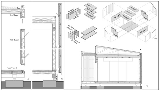
Figure 11.
Construction details and disassembly drawing for CSB, showing the strategy behind the reversible connections (a,b), the combination of the elements (c), and a full cross-section of the modular unit (d).
The device of the pressure joint between elements allows for the preservation of the integrity of the membrane layers (air, vapour, and waterproofing membranes) after repeated cycles of disassembly. For the same reason, most of the finishes were prefabricated on the supporting structures. The shape of the joints, mainly based on overlay or labyrinth arrangements [45], requires additional workings if the geometry of the connection needs any change for alternative use other than the intended one.
3.2. Preliminary Estimate of the Percentage of Reused Mass
3.2.1. Case Study A (CSA)
Alongside the production of a detailed BOQ, a preliminary assessment of the percentage of reused material was conducted. The results are reported by element number and hierarchy of disassembly. The score in each column represents the percentage of the reused mass if, at the end-of-life, the target were to revert the building to the relevant disassembly level. To clarify the reading of the results, let us focus on the first column, “Wall Type 1 (Mass)”, in Figure 12. If the decision at the end-of-life stage were to revert the building to its constituent materials, the percentage of reuse would be 87%, meaning that one would experience a loss of 13% of material destined either for recycling or landfill. On the other hand, if the end-of-life scenario is such that the reuse of the very elements is the target, then no loss of material would be experienced, yielding a percentage of reuse of 100%, which is the same as if the assembly were reused untouched. This scoring is in fact calculated as a ratio between the reused mass over the total mass employed. From Figure 12, the reader can see how the reused mass ranged from 65% to 92% at the material reuse level, from 84% to 97% at the parts level, and 100% at the elements or assembly reuse level.
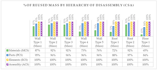
Figure 12.
Results of % of reused mass for CSA ordered by elements for each hierarchy of disassembly.
Further insight into the aforementioned can be seen by looking at rows 199, 200, 201, and 202 in Figure 13. Here three items are visible: an epoxy-resin finish chemically bonded to a wood-fibre panel on a substrate of an OSB panel.
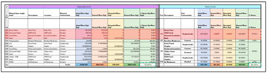
Figure 13.
Extract of the BOQ of the floor element for CSA showing how the reuse target has an impact on the circularity indicator.
These items belong to one bundle, called P1 (part 1). Separating the epoxy resin from the OSB panels and the wood-fibre panel (material reuse target) means, by virtue of the chemical bond, complete destruction of the three bonded layers (% of reuse 0), whereas, if it were kept in a bundle (part reuse target) and reused as such, the damage produced would amount just to the removal of the nails, yielding a percentage of reuse of 97.67% of the mass.
The spider web graph in Figure 14 offers a synoptical view of the performance of each element across the disassembly hierarchy. From a decision-making point of view, these results could inform the end-of-life strategy of the building, pinpointing the elements with the lowest circularity or the disassembly hierarchy level that requires improvement.
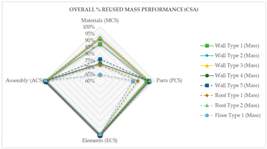
Figure 14.
Overall performance by % of reused mass for CSA.
Roof Type 2 is the best overall performing element (largest area) across the hierarchies and Floor Type 1 the worst (Figure 14).
3.2.2. Case Study B (CSB)
Reused mass ranged from 66% to 91% at the materials level and from 89% to 96% at the parts level, as shown in Figure 15. At the elements and assemblies levels, the reused mass was 100% as a result of the complete reversibility designed at those hierarchies.
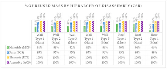
Figure 15.
Percentage of reused mass by disassembly hierarchies for CSB.
The results highlight for all elements a trend in having a performance that is increasingly lower if the reuse target moves toward the materials level.
Element Roof Type 2 was the best-performing one overall, with a score of 89% in terms of reuse of material, whereas element Wall Type 5 scored best in the reuse of parts, with a score of 96%. Roof Type 2 was the best performing overall and Floor Type 1 the worst (Figure 16).
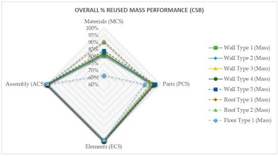
Figure 16.
Overall performance by % of reused mass for CSB.
The results of the percentage of reused mass are not to be interpreted as a metric for circularity, although their consideration complements the results in the following section and creates ground for a more comprehensive understanding of the relationship between the reused mass and the circularity indicator. Figure 17 shows how the same sheer variance between the reused mass at the materials and parts levels was noticed, for instance in P1, in accordance with the considerations made for Figure 13.
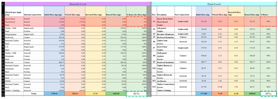
Figure 17.
Extract of the BOQ of the floor element for CSB showing how the reuse target has an impact on the circularity indicator.
3.3. Circularity Score Calculated in Accordance with Level(s)
3.3.1. Case Study A (CSA)
The calculations of the CI L.2.4 according to Level(s) revealed a score ranging from 62% to 82% at the materials level, from 91% to 96% at the parts level, from 90% to 100% at the elements level, and 100% at the assemblies level (Figure 18).
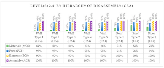
Figure 18.
CSA results for the Level(s) L.2.4 circularity indicator.
The graph depicted in Figure 19 shows that Wall Type 1 to 5 elements presented the worst-performing L2.4 values overall, whereas the elements Roof Type 2 and Floor Type 1 showed the best.
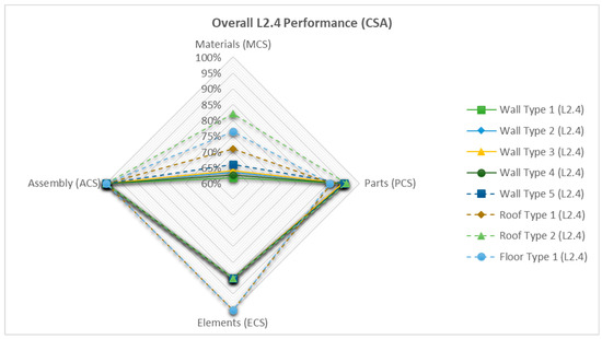
Figure 19.
Overall circularity performance according to Level(s) indicator L.2.4 (CSA).
3.3.2. Case Study B (CSB)
For CSB, the calculation of the performance indicator L2.4 in accordance with the Level(s) protocol yielded values from 73% to 83% at the materials level, from 91% to 96% at the parts level, and 100% for the assemblies and elements levels (Figure 20).
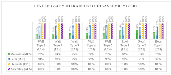
Figure 20.
Circularity scoring by level of disassembly hierarchy Level(s) 2.4.
Wall Type 1 to 5 scored poorly in terms of circularity when the raw materials were sought to be separated at end-of-life, whereas their circularity performance lined up with the other elements at higher disassembly hierarchies (Figure 21).
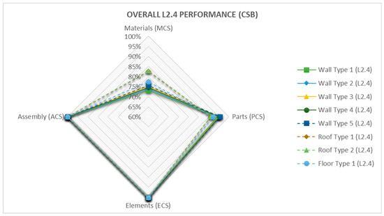
Figure 21.
Overall circularity performance according to Level(s) indicator L.2.4 (CSB).
The graphical representations in Figure 20 and Figure 21 align with the findings described in Section 3.2, highlighting a consistent trend in circularity scoring across different levels of hierarchy. Specifically, both figures demonstrate a progressive decrease in circularity scoring as we moved from the assemblies level to the materials level. Furthermore, the graphs illustrate that the circularity scoring remained relatively consistent within each level of hierarchy. This means that, within a specific hierarchy (e.g., assemblies or materials, etc.), the variations in circularity performance among different elements were relatively minimal.
3.4. Circularity Score According to MCI
3.4.1. Case Study A (CSA)
The MCI scoring returned a range between 67% and 78% at the materials level, from 87% to 96% at the parts level, from 93% to 100% at the elements level, and 100% at the assemblies level (Figure 22).
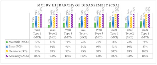
Figure 22.
Circularity scoring by level of disassembly hierarchy MCI (CSA).
The MCI performance of Wall Type 1 to 5, Roof Type 1, and Roof Type 2 was higher at the parts level than at the elements level. The lowest-performing element overall was Wall Type 2 (Figure 23).
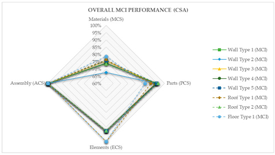
Figure 23.
Overall circularity performance calculated in accordance with MCI for (CSA).
The reason why some elements scored higher at the parts level rather than at the element level is discussed in the last section.
3.4.2. Case Study B (CSB)
For CSB, the MCI assessment method yielded circularity values ranging from 73% to 74% at the materials level, from 89% to 94% for the parts level, 100% for the elements level, and 100% for the assemblies level, as shown in Figure 24 and Figure 25.
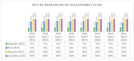
Figure 24.
MCI by disassembly hierarchy for CSB.
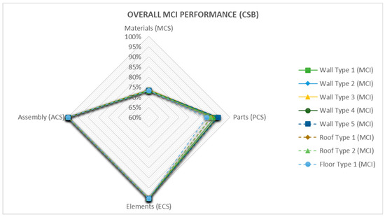
Figure 25.
Circularity performance of MCI for CSB.
The worst-performing element overall was Floor Type 1, and the best was Wall Type 5 (Figure 25). However, the difference was minimal and the results were rather homogeneous at each hierarchy.
4. Discussion
The findings of this study highlight the importance of considering different disassembly scales and hierarchies when approaching circularity in architectural design. In both the MCI and Level(s) methods, the impact of structural connectivity and the overall circularity strategy underlying the building design are considered indirectly. By restricting the focus on a materials-based approach, the protocols interpret the degree of disassembly as a form of embodied circularity of the materials affected by each type of connection. However, the protocols can be scaled to provide circularity metrics in accordance with the hierarchy of disassembly. In fact, Design for Disassembly (DfD) encompasses the implementation of circularity at various scales, including materials, parts, elements, and assemblies, with the materials level representing the lowest level of organisation in a building. Therefore, designing circularity at this level only disregards the higher hierarchies. In a timber frame panel where studs, beams, and OSB panels are connected using nails and sealant, separation of these materials for reuse would result in a low circularity score due to the irreversible damage caused by connections with a low degree of disassembly. However, if the entire element, i.e., the timber frame panel, is reused without separating the materials, the circularity score would be higher, as no material is lost during the reuse process. This simple scenario is indicative of the importance of recognising that a circularity design based solely on the separation of materials may not fully capture the diverse disassembly strategies employed by designers. Within the same building, different circularity scores may emerge when implementing circularity at the assemblies, elements, parts, or materials level, as demonstrated by this study. Considering these factors, it is necessary to disentangle the impact of DfD strategies on circularity scoring to enable meaningful comparisons of different DfD solutions within the same project, regardless of the bill of materials involved. The results presented in the previous sections clearly show a variability of the circularity indicators related to the connections implemented at each level of disassembly. Depending on the envisioned reuse scenario at the end of the building’s life, at least four circularity performance indicators can be calculated, as anticipated in Figure 8. When the hierarchy is assemblies > elements > parts > materials, the results show that generally the higher the hierarchy (i.e., assembly) the higher the circularity score and, by extension, that ACS > ECS > PCS > MCS. The aforementioned correspondence is partially confirmed by the results for some items scored.
In fact, the results from MCI and L2.4 for CSA returned higher scoring at the parts (PCS) over the element level (ECS) for some items. In CSA, the presence of higher density of irreversible or partially reversible connections at the hierarchy of elements determined a lower circularity performance at this level, whereas the high density of reversible connections at the hierarchy of parts determined a PCS higher than the ECS. This constitutes evidence of the dependency of the CI on the connectivity strategy at each hierarchy. The study, despite this aspect, shows that, invariantly of the metric used, there is clearly a variability of the CI independent of the deconstruction hierarchy. It is then worth raising the point of the importance of the structural strategy and, specifically, the deconstruction strategy, at the early stage of the architectural design (the reference here is to RIBA stages 0, 1, and 2 (UK) and the Italian equivalent preliminary design stage).
In the context of concept design, utilizing Level(s) as the primary protocol for evaluating circularity offers significant advantages due to its minimal assumptions and straightforward structure. However, MCI is better suited for later design stages, when more detailed information is known in terms of procurement and waste management. There is an opportunity to explore the potential of combining the strengths of MCI and Level(s) to create a comprehensive yet simplified approach that supports the early implementation of circularity in design. This could involve integrating the concept of disassembly hierarchy from Level(s) and applying the methodology of MCI, resulting in a hybrid assessment method. Although this idea was partially applied in this study, further methodical formalisation of this method represents a possible long-term outcome of this research. This study emphasises the importance of considering different disassembly scales when approaching circularity in design. Circular architectural concept design should be expressed through a set of circularity performance indicators associated with each disassembly hierarchy to be comprehensive and fit for discussion.
An approach of this kind enhances flexibility and freedom of choice in terms of structural arrangement, modularity, and space flexibility, enabling a broader range of materials to be considered for circular strategies, providing extensive information for the development of the design at different scales. It also offers the opportunity to compare strategies (Figure 26) rather than materials when it comes to DfD and empowers a more comprehensive quantitative design of circularity to the widest range of options. The comparison of the four hierarchies using a spider web diagram of the weighted average of the results obtained can be used as an early-stage design tool to compare alternative options of the same building or diverse building typologies (Figure 27). In that case, the overall connectivity strategy concept for CSB showed better performances than CSA according to the results of L2.4 and MCI. However, the diagrams also show that the advantage of CSB over CSA is associated with two main reuse scenarios, materials and elements. It can be inferred, however, that for reuse of parts and assemblies (for this scenario the building is reused without being deconstructed) the designs are interchangeable, and other metrics (LCA, LCC) would take the lead in the decision-making process.
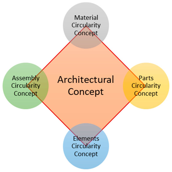
Figure 26.
Diagrammatic representation of the architectural concept design approach based on the hierarchical deconstruction strategy.
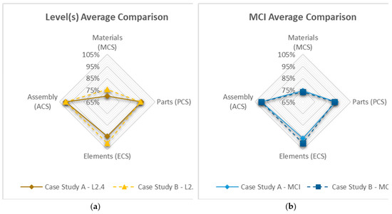
Figure 27.
Weighted average comparison of the case studies according to L2.4 (a) and MCI (b).
By examining the hierarchy of disassembly, materials with limited inherent circularity can still contribute to virtuous circular loops through intended reuse strategies at the end of their life, even in the presence of irreversible bonding.
The conclusions can be draw and summarised as follows:
- The integration of Design for Disassembly (DfD) principles into the architectural concept design stage encourages designers to consider different scales of the building beyond just the materials used.
- The Material Circularity Indicator (MCI) and Level(s) circularity assessment protocols can be effectively adapted to a hierarchical approach to implementing DfD in architectural design. Despite some differences, they can be employed at the concept-design stage as decision-making tools.
- Circularity indicators may vary at different scales or hierarchies, highlighting the importance of considering multiple levels of disassembly in circularity assessments.
- The hierarchies of disassembly are closely related to the end-of-life strategy of a building, emphasising the significance of considering the entire life cycle in circular design.
- Consideration of end-of-life scenarios should be addressed in the concept-design stage.
- For a comprehensive and flexible approach to conceptualising circularity in architectural design, the four main hierarchies (materials, parts, elements, assemblies) should be considered.
- A concept design based on the hierarchy of disassembly enables the integration of materials with limited inherent circularity into virtuous circular loops through strategic reuse, even in the presence of irreversible bonding.
- The implementation of circularity disrupts the standard approach to concept design and necessitates the consideration of construction technology from the early stages of design development, with consequent requirements of design effort, time, and resources.
Moving forward, the reader should have noticed that this paper presents findings associated with two case studies, both modular, and developed to the highest extent of circularity. Therefore, future development of this research is going to be an extension of the sample of case studies to a larger number and to examine non-modular buildings to confirm the approach presented and capture a wider range of circularity scores that could strengthen its validity. The study will proceed with the assessment and scoring of buildings of a heterogeneous nature of the structural typology and materials used but that have been designed with specific attention to the implementation of DfD at all stages of the design. From a longer-term perspective, this research raises questions regarding whether a similar hierarchical approach could be adopted on existing or historical buildings and whether a coherent and replicable design methodology can be drawn from that in order to provide designers with tools and guidelines for the most effective and practical implementation of circularity at various levels, different scales, and different heterogeneous architectural contexts.
Author Contributions
Conceptualization, F.I., L.C. and M.R.; methodology, F.I.; formal analysis, F.I.; investigation, F.I.; writing—original draft preparation, F.I.; writing—review and editing, F.I., L.C. and M.R.; visualization, F.I.; supervision, L.C. and M.R.; funding acquisition, L.C. All authors have read and agreed to the published version of the manuscript.
Funding
This research received no external funding.
Data Availability Statement
Not applicable.
Acknowledgments
Part of the general arrangement and construction drawings were kindly supplied by Arch. Francesca Camerin (CSA) and Arch. Francesco Pozzobon (CSB).
Conflicts of Interest
The authors declare no conflict of interest.
References
- Dokter, G.; Thuvander, L.; Rahe, U. How circular is current design practice? Investigating perspectives across industrial design and architecture in the transition towards a circular economy. Sustain. Prod. Consum. 2021, 26, 692–708. [Google Scholar] [CrossRef]
- Hart, J.; Adams, K.; Giesekam, J.; Tingley, D.D.; Pomponi, F. Barriers and drivers in a circular economy: The case of the built environment. Procedia CIRP 2019, 80, 619–624. Available online: https://www.sciencedirect.com/science/article/pii/S2212827118312940 (accessed on 23 March 2023). [CrossRef]
- Franconi, A. Multiple Design Perspectives for the Transition to the Circular Economy Managing: Design Strategies Between Systems, Designers and Time. Ph.D. Thesis, Università Iuav di Venezia, Venezia, Italy, 2020. Available online: https://www.researchgate.net/publication/351267555_Multiple_Design_Perspectives_for_the_Transition_to_the_Circular_Economy_Managing_Design_Strategies_Between_Systems_Designers_and_Time (accessed on 20 February 2023).
- Mestre, A.; Cooper, T. Circular Product Design. A Multiple Loops Life Cycle Design Approach for the Circular Economy. Null 2017, 20, S1620–S1635. [Google Scholar] [CrossRef]
- Kirchherr, J.; Reike, D.; Hekkert, M. Conceptualizing the circular economy: An analysis of 114 definitions. Resour. Conserv. Recycl. 2017, 127, 221–232. [Google Scholar] [CrossRef]
- Moreno, M.; De los Rios, C.; Rowe, Z.; Charnley, F. A Conceptual Framework for Circular Design. Sustainability 2016, 8, 937. [Google Scholar] [CrossRef]
- Charnley, F.; Lemon, M.; Evans, S. Exploring the process of whole system design. Des. Stud. 2011, 32, 156–179. [Google Scholar] [CrossRef]
- Murray, A.; Skene, K.; Haynes, K. The Circular Economy: An Interdisciplinary Exploration of the Concept and Application in a Global Context. J. Bus. Ethics 2017, 140, 369–380. [Google Scholar] [CrossRef]
- Charef, R.; Morel, J.; Rakhshan, K. Barriers to Implementing the Circular Economy in the Construction Industry: A Critical Review. Sustainability 2021, 13, 12989. [Google Scholar] [CrossRef]
- Çetin, S.; De Wolf, C.E.L.; Bocken, N. Circular Digital Built Environment: An Emerging Framework. Sustainability 2021, 13, 6348. [Google Scholar] [CrossRef]
- Osobajo, O.A.; Oke, A.; Omotayo, T.; Obi, L.I. A systematic review of circular economy research in the construction industry. Smart Sustain. Built Environ. 2022, 11, 39–64. [Google Scholar] [CrossRef]
- Zhang, N.; Han, Q.; de Vries, B. Building Circularity Assessment in the Architecture, Engineering, and Construction Industry: A New Framework. Sustainability 2021, 13, 12466. [Google Scholar] [CrossRef]
- Benachio, G.L.F.; Freitas, M.d.C.D.; Tavares, S.F. Circular economy in the construction industry: A systematic literature review. J. Clean. Prod. 2020, 260, 121046. [Google Scholar] [CrossRef]
- Walzberg, J.; Lonca, G.; Hanes, R.J.; Eberle, A.L.; Carpenter, A.; Heath, G.A. Do We Need a New Sustainability Assessment Method for the Circular Economy? A Critical Literature Review. Front. Sustain. 2021, 1. Available online: https://www.frontiersin.org/articles/10.3389/frsus.2020.620047 (accessed on 1 April 2023). [CrossRef]
- Goddin, J.; Marshall, K.; Pereira, A.; Herrmann, S.; Tuppen, C. Circularity Indicators Methodology. Ellen MacArthur Found. Ansys Granta 2019, 1, 1–64. [Google Scholar]
- ISO BS ISO 21931-1:2022; Sustainability in Buildings and Civil Engineering Works. Framework for Methods of Assessment of the Environmental, Social and Economic Performance of Construction Works as a Basis for Sustainability Assessment. 2022. Available online: https://www.iso.org/obp/ui/en/#iso:std:iso:21931:-1:ed-2:v1:en (accessed on 21 May 2023).
- European_Commission Towards a circular economy: A zero waste programme for Europe. COM(2014) 398 final/2. Eur. Comm. 2014. Available online: https://hytechcycling.eu/wp-content/uploads/Towards-a-circular-economy-A-zero-waste-programme-for-Europe.pdf (accessed on 21 May 2023).
- Dodd, N.; Traverso, M.; Donatello, S.; Cordella, M. Level(s): A Common EU framework of core sustainability indicators for office and residential buildings: Parts 1 and 2, introduction to level(s) and how it works (Beta v1.0). Eur. Comm. Jt. Res. Cent. 2017. Available online: https://publications.jrc.ec.europa.eu/repository/handle/JRC109285 (accessed on 21 May 2023).
- Level(s) Common Framework Documents. Available online: https://susproc.jrc.ec.europa.eu/product-bureau/product-groups/412/documents (accessed on 14 April 2023).
- Dodd, N.; Cordella, M.; Donatello, S. Level(s) Indicator 2.4: Design for Deconstruction User Manual: Introductory Briefing, Instructions and Guidance. Joint Research Centre 2021. Available online: https://academy.europa.eu/pluginfile.php/15859/mod_scorm/content/1/resources/75127/76593/UM3_Indicator_2.4_v.2.0_clean_20.07.2021.pdf (accessed on 15 January 2023).
- European Commission DIRECTIVE 2008/98/EC OF THE EUROPEAN PARLIAMENT AND OF THE COUNCIL of 19 November 2008 on Waste and Repealing Certain Directives (Text with EEA Relevance). 2008. Available online: https://eur-lex.europa.eu/legal-content/EN/TXT/?uri=celex%3A32008L0098 (accessed on 21 May 2023).
- Kirchherr, J.; Piscicelli, L.; Bour, R.; Kostense-Smit, E.; Muller, J.; Huibrechtse-Truijens, A.; Hekkert, M. Barriers to the Circular Economy: Evidence from the European Union (EU). Ecol. Econ. 2018, 150, 264–272. [Google Scholar] [CrossRef]
- Khadim, N.; Agliata, R.; Marino, A.; Thaheem, M.J.; Mollo, L. Critical review of nano and micro-level building circularity indicators and frameworks. J. Clean Prod. 2022, 357, 131859. [Google Scholar] [CrossRef]
- Anastasiades, K.; Blom, J.; Audenaert, A. Circular Construction Indicator: Assessing Circularity in the Design, Construction, and End-of-Life Phase. Recycling 2023, 8, 29. [Google Scholar] [CrossRef]
- O’Grady, T.; Minunno, R.; Chong, H.; Morrison, G.M. Design for disassembly, deconstruction and resilience: A circular economy index for the built environment. Resour. Conserv. Recycl. 2021, 175, 105847. [Google Scholar] [CrossRef]
- Incelli, F.; Cardellicchio, L. Designing a steel connection with a high degree of disassembly: A practice-based experience. Techne 2021, 104–113. [Google Scholar] [CrossRef]
- Durmisevic, E. Transformable Building Structures. Design for Disassembly as a Way to Introduce Sustainable Engineering to Building Design & Construction. Ph.D. Thesis, Technische Universiteit Delft, Delft, The Netherlands, 2006. Available online: http://resolver.tudelft.nl/uuid:9d2406e5-0cce-4788-8ee0-c19cbf38ea9a (accessed on 3 May 2023).
- Durmisevic, E. Circular Economy in Construction Design Strategies for Reversible Buildings. The Netherlands, 2019; pp. 1–94. Available online: https://www.bamb2020.eu/wp-content/uploads/2019/05/Reversible-Building-Design-Strateges.pdf (accessed on 21 February 2023).
- Beurskens, P.R.; Durmisevic, E. Increasing reuse potential by taking a whole life-cycle perspective on the dimensional coordination of building products. In Proceedings of the 3rd Green Design Conference Proceedings, Mostar, Bosnia-Herzegovina, 4–8 October 2017; Sarajevo Green Design Foundation: Sarajevo, Bosnia-Herzegovina, 2017; pp. 28–38. Available online: https://ris.utwente.nl/ws/portalfiles/portal/24832189/Conference_Proceedings_3rd_Green_Design_Conference_web.pdf (accessed on 4 April 2023).
- Durmisevic, E.; Berg, M.C.; Atteya, U. Design Support for Revisable Buildings with Focus on Visualizing and simulating Transformation Capacity during Initial Design Phase. In Proceedings of the International HISER Conference on Advances in Recycling and Management of Construction and Demolition Waste, Delft, The Netherlands, 21–23 June 2017; TU Delft Library: Delf, The Netherlands, 2017; pp. 264–270. [Google Scholar]
- Bertino, G.; Kisser, J.; Zeilinger, J.; Langergraber, G.; Fischer, T.; Oesterreicher, D. Fundamentals of Building Deconstruction as a Circular Economy Strategy for the Reuse of Construction Materials. Appl Sci 2021, 11, 939. [Google Scholar] [CrossRef]
- Zhang, C.; Hu, M.; Di Maio, F.; Sprecher, B.; Yang, X.; Tukker, A. An overview of the waste hierarchy framework for analyzing the circularity in construction and demolition waste management in Europe. Sci. Total Environ. 2022, 803, 149892. [Google Scholar] [CrossRef]
- Sáez-de-Guinoa, A.; Zambrana-Vasquez, D.; Fernández, V.; Bartolomé, C. Circular Economy in the European Construction Sector: A Review of Strategies for Implementation in Building Renovation. Energies 2022, 15, 4747. [Google Scholar] [CrossRef]
- van Stijn, A.; Gruis, V. Towards a circular built environment: An integral design tool for circular building components. Smart Sustain. Built Environ. 2020, 9, 635–653. [Google Scholar] [CrossRef]
- van Eck, N.J.; Waltman, L. Citation-based clustering of publications using CitNetExplorer and VOSviewer. Scientometrics 2017, 111, 1053–1070. [Google Scholar] [CrossRef] [PubMed]
- Raworth, K. A Doughnut for the Anthropocene: Humanity’s compass in the 21st century. Lancet Planet. Health 2017, 1, e48–e49. [Google Scholar] [CrossRef] [PubMed]
- Palumbo, E.; Rossetti, M.; Incelli, F.; Panozzo, C.; Camerin, F. Towards the circular building as design practice: A Design for Disassembly case study. In Proceedings of the Conference Pre-Free, Up-Down, Re-Cycle: Pratiche Tradizionali e Tecnologie Innovative per L’end of Waste: 4, Roma, Italy, 28 May 2021; Anteferma: Conegliano, Italy, 2021; pp. 222–235. [Google Scholar]
- Camerin, F.; Incelli, F.; Rossetti, M. Facing Time. Temporary Wooden Housing Units for the Non-Self-Sufficient Elderly. TECHNE-J. Technol. Archit. Environ. 2020, 282–291. Available online: https://oaj.fupress.net/index.php/techne/article/view/8268 (accessed on 29 June 2023).
- Ciampa, F.; Croatto, G.; Rossetti, M.; De Carli, M.; Chinellato, F.; Turrini, U.; Bertolazzi, A.; Incelli, F. Architectural technology responds to the environmental crisis: Participatory design in an emergency context [La tecnologia dell’architettura risponde alla crisi ambientale: La progettazione partecipata in ambito emergenziale]. Valori E Valutazioni 2022, 30, 119–134. [Google Scholar] [CrossRef]
- Mulhall, D.; Braungart, M.; Hansen, K. Creating Buildings with Positive Impacts. 2019. Available online: http://resolver.tudelft.nl/uuid:5eea906e-4d5a-4086-be4b-4cfab969b2a0 (accessed on 17 February 2023).
- Eguez, A. Compliance with the EU waste hierarchy: A matter of stringency, enforcement, and time. J. Environ. Manag. 2021, 280, 111672. [Google Scholar] [CrossRef]
- Jiang, L.; Bhochhibhoya, S.; Slot, N.; de Graaf, R. Measuring product-level circularity performance: An economic value-based metric with the indicator of residual value. Resour. Conserv. Recycl. 2022, 186, 106541. [Google Scholar] [CrossRef]
- Brunet-Navarro, P.; Jochheim, H.; Muys, B. The effect of increasing lifespan and recycling rate on carbon storage in wood products from theoretical model to application for the European wood sector. Mitig. Adapt. Strat. Glob. Chang. 2017, 22, 1193–1205. [Google Scholar] [CrossRef] [PubMed]
- Braakman, L.; Bhochhibhoya, S.; de Graaf, R. Exploring the relationship between the level of circularity and the life cycle costs of a one-family house. Resour. Conserv. Recycl. 2021, 164, 105149. [Google Scholar] [CrossRef]
- Herzog, T.; Krippner, R.; Lang, W. Facade Construction Manual, 3rd ed.; DETAIL Business Information GmbH: Munich, Germany, 2021. [Google Scholar]
- Arup-Ktn. Design Innovation for the Circular Economy the Materials and Design Exchange Project for End-of-Life Building Façades Knowledge Transfer Network. ARUP. 2021. Available online: https://www.arup.com/-/media/arup/files/publications/f/ktn_arup_facade_report_web.pdf (accessed on 25 May 2023).


Disclaimer/Publisher’s Note: The statements, opinions and data contained in all publications are solely those of the individual author(s) and contributor(s) and not of MDPI and/or the editor(s). MDPI and/or the editor(s) disclaim responsibility for any injury to people or property resulting from any ideas, methods, instructions or products referred to in the content. |
© 2023 by the authors. Licensee MDPI, Basel, Switzerland. This article is an open access article distributed under the terms and conditions of the Creative Commons Attribution (CC BY) license (https://creativecommons.org/licenses/by/4.0/).