Abstract
The steel racks on the floor are seen as live loads in the current design process, ignoring the interaction with the supporting frames. In this paper, multiple steel racks with different masses and stiffnesses are placed on the first floor of a two-story main structure to form different real structures (RS). The corresponding simplified structures (SS) are frames with the mass of steel racks concentrated on the first floor of the main structure. Modal analysis is performed to analyze the relationship between the periods of RS and SS in the cross-aisle direction. Firstly, the beams on the first floor are assumed to be infinitely rigid. The relationship between the periods of the rack TRk, the simplified structure TSS, and the real structure TRS under different mass ratios α is established, and an accurate equation relating TRS with TRk and TSS is proposed. Moreover, by considering the influence of finite beam stiffness, the interaction between racks and the main structure is studied by constructing different analysis models. The effect of the main structure on the racks is reflected by a combined system consisting of beams and racks. A modified model, distinguished from SS by considering the effect of no-mass racks, is constructed to study the strengthening effect of the racks on the first-floor beams. The effect of the top connecting bars is also analyzed.
1. Introduction
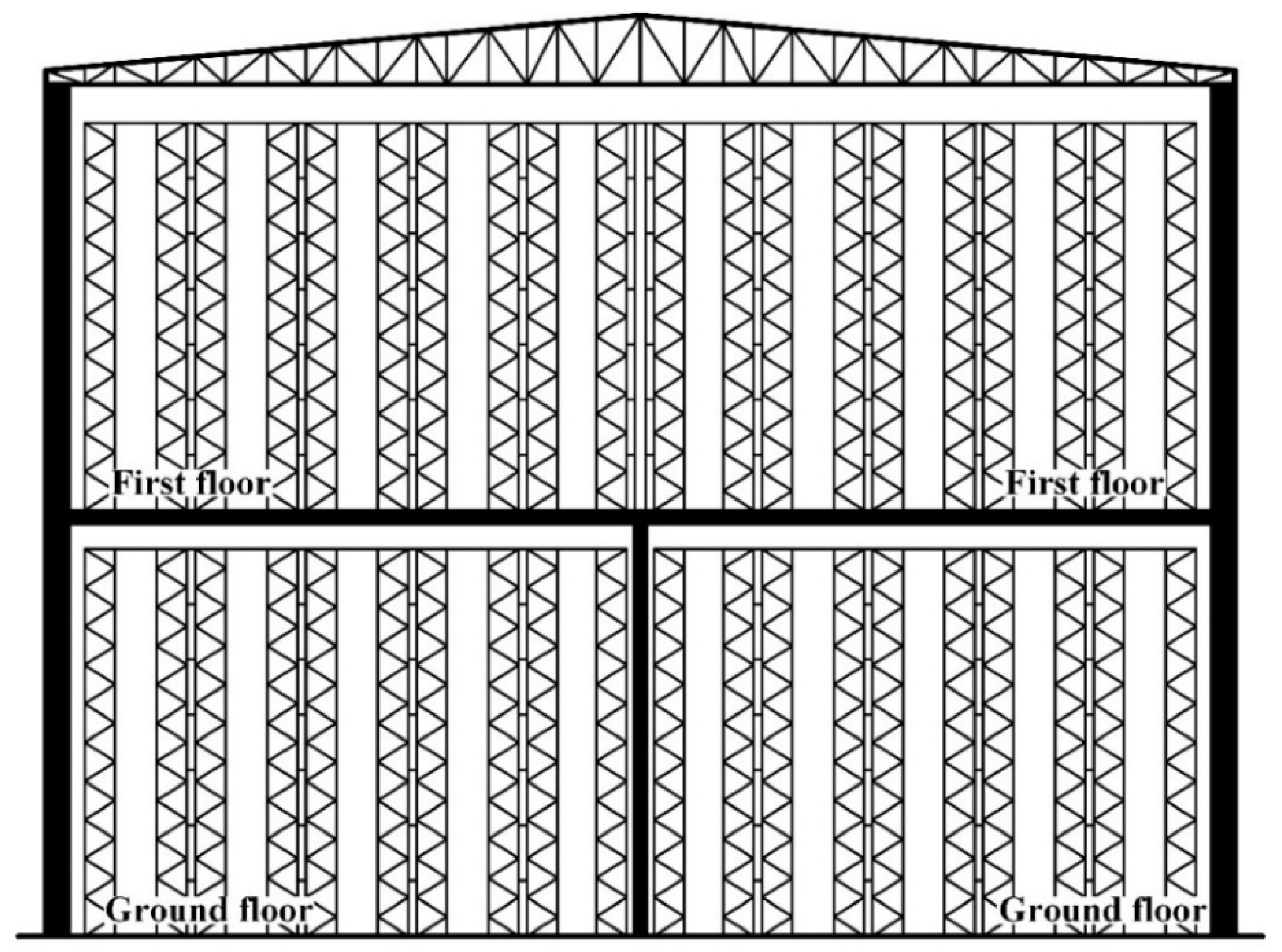
In recent years, a large number of two-story warehouses have been built in China, as shown in Figure 1. The warehouse height can reach 20–25 m, and the story height is about 10–12 m. The cold-formed steel storage racks are installed on the ground and the first floor to make effective use of precious spaces.

Figure 1.
A Two-story Warehouse.
Currently, the steel racks and main structures are designed, respectively, by rack manufacturers [1] and authorized institutes for two-story warehouses where racks are installed both on the ground and first floors. The steel racks are regarded as nonstructural components fixed to the ground [2,3,4,5]. Since the arrangement of steel racks is usually uncertain in the early design stage, the steel racks are simplified as additional live loads and the interaction between the main structures and the racks is ignored.
These two-story warehouses with racks installed on the first floor can be seen as primary-secondary combined systems, where the interaction between the primary and secondary structures can be called the Primary-Secondary Structure Interaction (PSSI), ensuring that the structure performs as a whole system. By considering the influences of PSSI, the floor response spectrum (FRS) method is applied to check the strength of non-structural members and the connections between non-structural members and supporting structures. For the calculation of primary-secondary combined systems, Sackman and Der Kiureghian [6,7] adopted the perturbation theory based on the dynamic properties of the primary and secondary structures. However, this method, based on the available literature, is only suitable when the secondary system is relatively light (usually below 1%) compared with the total mass of the whole system [8,9,10,11,12,13].
The FRS approach has attached much attention recently, however, these research works [14,15,16,17,18,19,20,21,22] concentrated on the simplified single-degree-of-freedom (SDOF) secondary system and elastic and inelastic multi-degree-of-freedom (MDOF) primary structure systems. It should be noted that secondary constructions may be connected to more than two locations in practical engineering, but the FRS method only allows for the construction of one or two points of attachment.
For the large two-story warehouse described in Figure 1, the racks on the first floor enlarge the demand on the stiffness of the floor, so the floor slabs of the main structures are generally made of reinforced concrete with thicknesses of 200–250 mm. On the first floors of the main structures, the dead load is 5–8 kN/m2 and the live load is usually as high as 20 kN/m2. Under these loading conditions, the mass of goods on the steel racks can account for more than 70% of the total mass of the structures. The current FRS approach is mainly for structures where the mass from the secondary equipment is very small and is not applicable for frames investigated in this paper where most of the mass is from secondary structures.
Meanwhile, the rack is a multistory structure with a height of 8 m–12 m and should be treated as an MDOF secondary system. Thus, the racks on the first floor should be considered as multiple identical MDOF secondary systems interconnected at the top. The interaction between multiple MDOF secondary systems is not considered in the current FRS approach. Therefore, a new analysis must be carried out so that the FRS approach is modified for possible future applications.
In the current design specifications involving multistory racks, no specific design requirements and methods are given for the racks installed on the first floor. It is specified in ASCE 7 [2] that when the weight of a nonstructural element is not less than 25% of the effective seismic weight of the structure, the nonstructural element is regarded as a nonbuilding structure. In addition, when the nonbuilding structure weight is not less than 25% of the combined effective seismic weights of the whole system, the different fundamental period T of the nonbuilding structure leads to different calculating methods. When T is less than 0.06 s, the nonbuilding structure should be treated as a rigid element with appropriate distribution of its effective seismic weight, and it can be simplified as an additional mass when designing the supporting structures. This method is similar to the method used when the mass of the supported nonbuilding structure is less than 25% of the mass of the combined system. However, when T is not less than 0.06 s, the supporting structure and nonbuilding structure should be regarded as a combined system with the appropriate stiffness and effective seismic weight distributions. Moreover, Chinese Codes GB50011 [23] and JGJ339 [24] only specify the seismic design method for the non-structural component of buildings when its mass is less than 10% of the floor.
A two-story frame was constructed by Zhang and Tong [25], where the racks were installed on the first floor. Dynamic history analysis on the overall structures was conducted. The elastic shear force spectra of the frames and racks were studied to verify the applicability of the simplified design method where the racks are regarded as live loads. Simplified design methods for racks and frames were proposed and the period relationship for three types of models was established. The interaction between steel racks and the main structure is considered but the influence of the floor elasticity was neglected, and the mass of racks was constant during the research, so the applicability of the period relationship needs to be further verified.
Therefore, for the two-story main structures with racks installed on the first floor, both steel racks and main structures with different first vibration periods are selected to be combined into different real structures in this paper. The following analysis will be performed in the cross-aisle (CA) direction:
- (1)
- Modal analysis will be conducted to study the dynamic characteristics of the real structures and the simplified structures. The mass of racks is concentrated on the first floor of the main structures in the simplified structures. The relationship between the periods of the racks, the main structure, simplified structures, and real structures will be studied.
- (2)
- The influence of the mass ratio of the rack mass to the total mass of the first floor will be involved.
- (3)
- The influence of the floor beam stiffness will be considered.
- (4)
- The interaction between the main structures and the racks considering the stiffness of the floor will be discussed.
The spine-bracing system is always used in the down-aisle (DA) direction to bear the weight of seismic actions [2,4], representing a different aseismic structural system. Thus, it will be examined in future studies.
2. Calculation Models and Process
2.1. Calculation Models
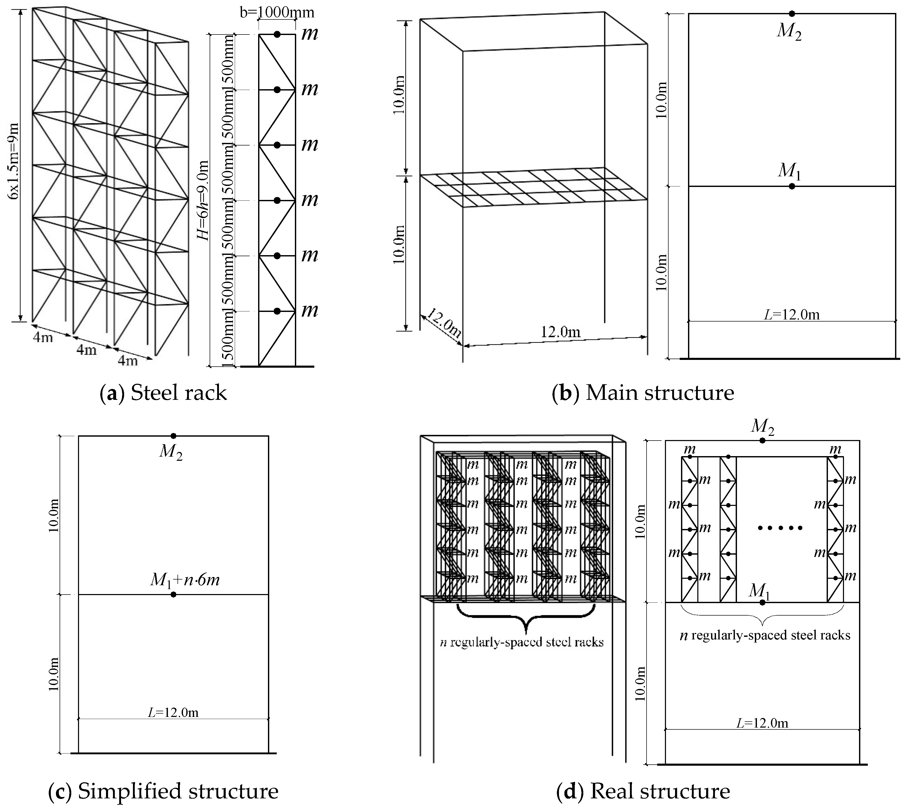
In this paper, a two-story structure (Figure 2d) with multiple six-story racks installed on the first floor is studied. Based on this original structure, the following four models are analyzed.
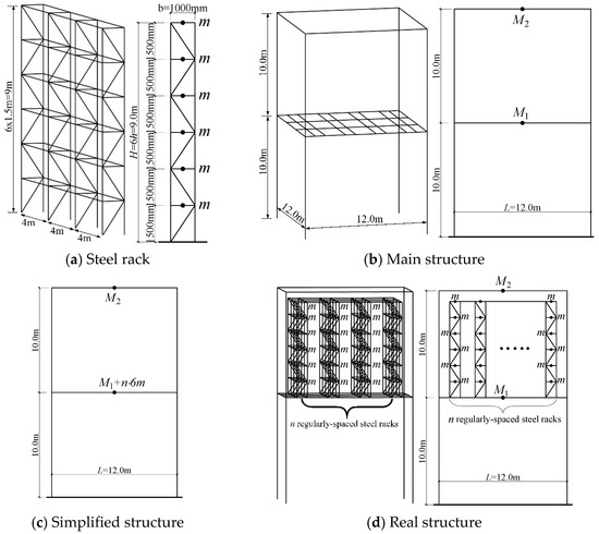
Figure 2.
Analysis models.
- The first model is the steel rack. As shown in Figure 2a, the steel rack height is 9.0 m with each story possessing a height of 1.5 m. There are four rack pieces in the DA direction, and the span between rack pieces is 4.0 m. The spacing between two rack columns is 1.0 m in the CA direction, and the effective mass of each story is denoted by m. The elasticity modulus of elements in the rack is denoted by ERk, and the natural period of the steel rack in the CA direction is denoted by TRk. The value of TRk is changed by varying ERk.
- A two-story steel frame is taken as the main structure, which is the second model and is described in Figure 2b. The spans of the main structure in two directions are both 12.0 m, and the height of each story is 10.0 m. The mass of the first floor is M1, and the mass of the roof is M2. The elastic modulus of the column of the main structure is denoted by EC, and the elastic modulus of the beam is denoted as EB. The natural period of the main structure in the CA direction is denoted by TSS0 (without including the masses of racks). Based on the given sections of main structural components, the period TSS0 will vary in the analysis through changing EC and EB.
- As presented in Figure 2c, the simplified structure is the third model analyzed in this paper, which is widely used in current seismic design. The total mass of racks is concentrated on the first floor of the main structure, and the interaction between the main structure and racks is ignored. Thus, the mass of the first floor in the simplified structure is denoted as , in which n represents the number of steel racks. The natural period of the simplified structure in the CA direction is denoted by TSS, which varies by changing the values of EC and EB. The simplified structure is abbreviated as SS in the following analysis for convenience.
- The last model is the real structure shown in Figure 2d, which is composed of the main structure and n regularly spaced steel racks with the same stiffness. As a result, the mass of the first floor is M1, while that of the roof is M2. The effective mass of each story m is considered as live loads subjected to the main structure, but the active points of the live loads are at their original positions, which is different from the SS. All the racks are interconnected at their tops. The natural period of the real structure in the CA direction is denoted by TRS, and the real structure is abbreviated as RS.
For the convenience of calculation, the sections of calculation models stay the same during the calculation. Table 1 summarizes the details of the calculation models in OpenSees, and the initial elasticity modulus is set as .

Table 1.
The Sections of Calculation Models.
2.2. Calculation Methods and Processes
The software OpenSees [26] is used for structural modal analysis. Since a large amount of modal analysis is carried out in this paper, MATLAB is used for data analysis. The steel members of calculation models are linearly elastic since the study is intended to serve the practical design. The beams and columns are simulated by elastic beam-column elements, and the elastic truss elements are used to model the braces of the racks. For the convenience of calculation, the sections of calculation models stay the same during the calculation. In addition, the masses of the main structures in OpenSees are M1 = 8.155 × 10⁴ kg and M2 = 2.5 × 10⁴ kg. The seismic masses are assumed to be combined on the nodes in terms of numerical modeling. Furthermore, because concrete slabs are usually used on the floor, a rigid diaphragm is applied for all floors [27]. The connections between beams and columns and between columns and foundations are set to be rigid. For the real structures with racks on the first floor, the uprights of racks are simply supported on the floor beams in the models, which means that only translational restraints are given to the bottom nodes of the rack uprights.
Two types of modal analysis are firstly defined as follows:
Modal Analysis 1 (MA1): The period TRk of the steel rack remains constant, and the period TSS0 of the main structure changes continuously.
Modal Analysis 2 (MA2): The period TSS0 of the main structure remains constant, and the period TRk of the steel rack changes continuously.
The number of steel racks n and the mass of each rack story m varies during the calculation. For the convenience of calculation, the sections of calculation models stay the same during the calculation, and the change of the periods of different calculation models will be realized by changing the elastic modulus of the structural members of models.
Based on the four calculation models mentioned above, the following aspects are studied respectively:
- (1)
- The beam stiffness of the first floor is infinite (), which means the influence of the elasticity of the first floor of the main structure is not considered.
Modal analysis is performed on both RSs and SSs to calculate periods TRS and TSS, and the relationship between TSS, TRk, and TRS is studied in MA1 and MA2, respectively. In these cases, the period TSS0 will be varied by changing the elastic modulus EC of the columns of the main structure.
- (2)
- When the beam stiffness of the first floor is finite, the relationship between TSS, TRk, and TRS is also studied in MA1 and MA2. In these cases, the period TSS0 will be varied by changing the elastic modulus EC (column) and EB (beam) of the main structure simultaneously.
- (3)
- The interaction between the regularly spaced steel racks and the main structure is then studied, considering the influence of the floor elasticity of the main structure.
3. Period Relationship with Infinite Beam Stiffness
3.1. Rack Periods
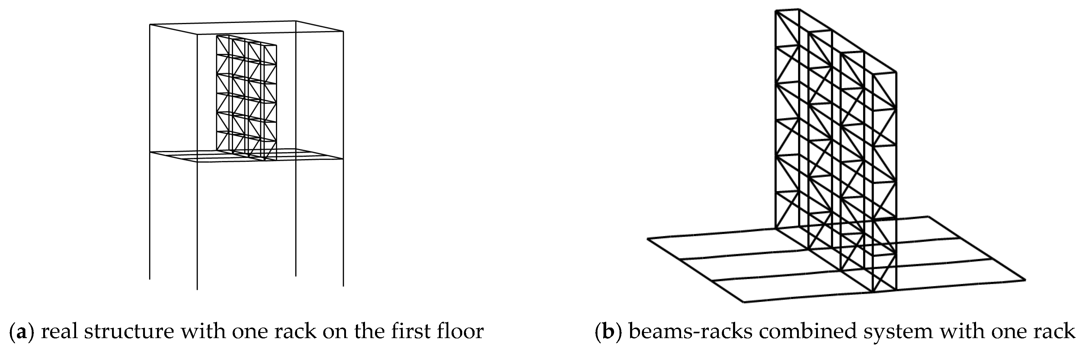
As shown in Figure 2a, the period of an independent rack fixed on the ground is TRk. When this rack is installed on the first floor of the main structure (Figure 3a), the beams become the elastic support of the racks. As a result, the period of the rack installed on the first floor will change. Therefore, a combined system consisting of floor beams and racks can be constructed with the beams being fixed, and the period of this beams-racks combined system is denoted by , where the subscript n represents the number of racks. The combined system with one rack is shown in Figure 3b and the period is .
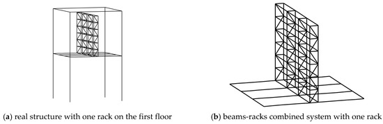
Figure 3.
Real structure with one rack on the first floor.
In this section, the beams of the first floor are assumed to be infinitely rigid (). Given the mass m of each rack floor, the elasticity modulus of the rack ERk is modified to obtain an independent rack with the period TRk = 1.0 s. The period of the beams-racks combined system with one rack can be obtained as , indicating that TRk does not change if the first-floor beams are infinitely rigid.
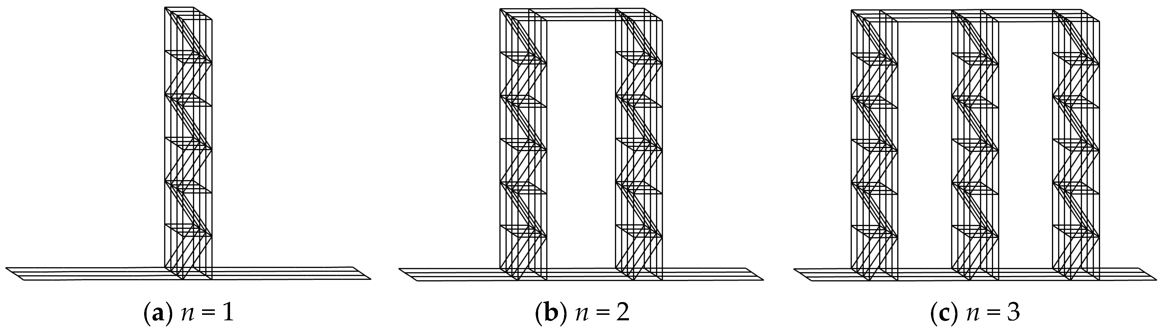
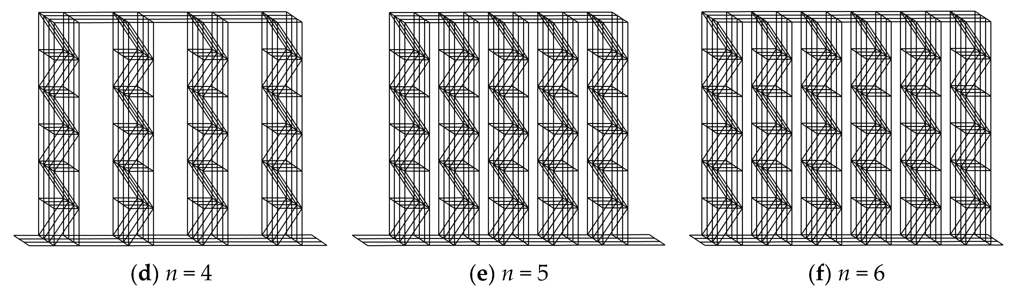
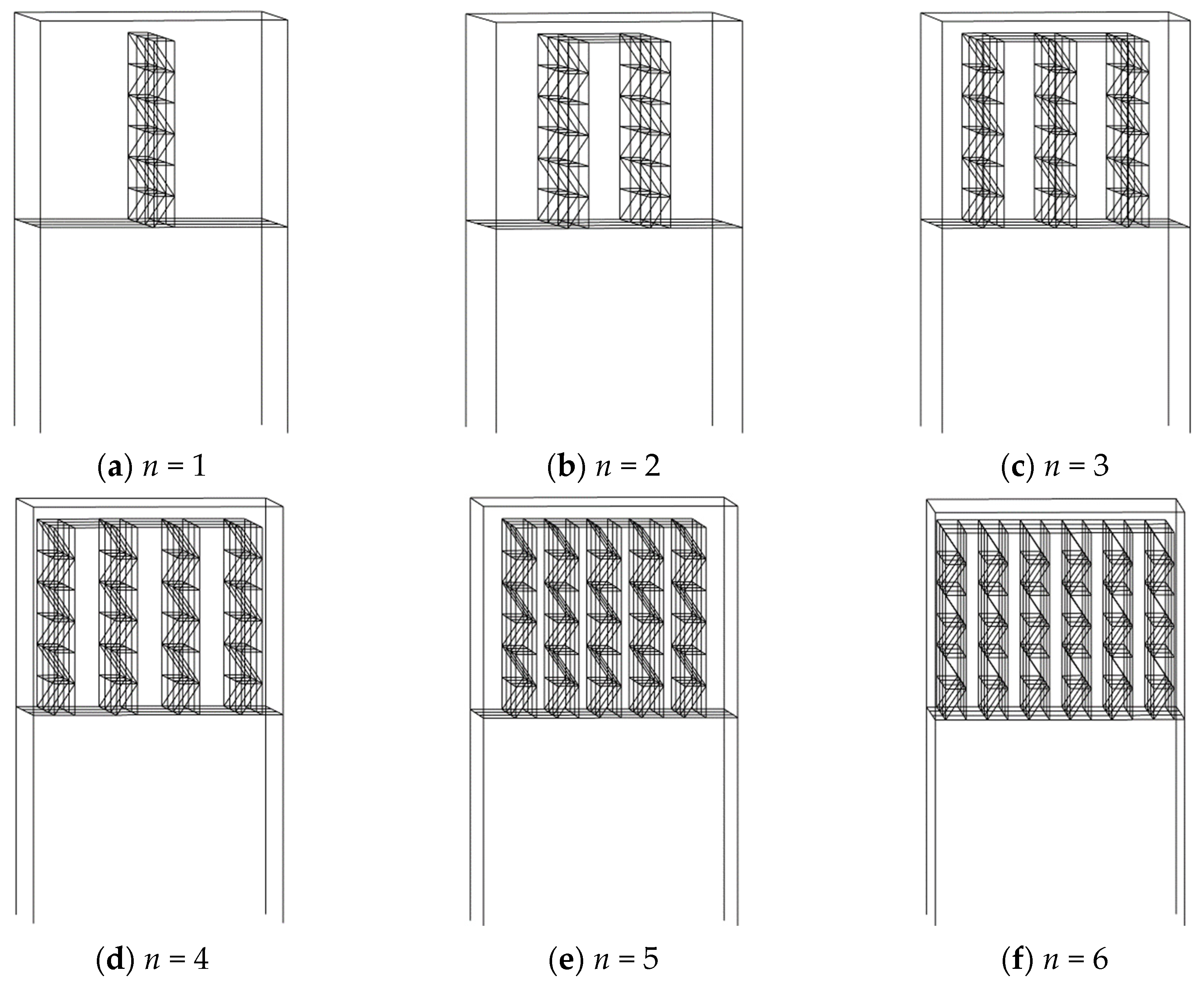
As the number of racks increases from 1 to 6, different beams-racks combined systems are shown in Figure 4. The connections between the racks at their tops ensure that all racks in the combined system vibrate in the same first vibration mode, as shown in Figure 5. It can be seen that without considering the influence of floor beam stiffness (), the number and the arrangement of racks do not affect the modal shape of beams-racks combined systems, and the periods of the six combined systems are the same, i.e., . Therefore, the vibration characteristics of the combined systems with n racks are consistent with those of the combined system with one rack whose masses and stiffness are multiplied by n (Figure 6).
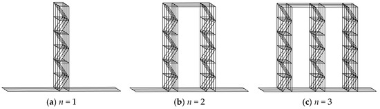

Figure 4.
The beams-racks combined system with n racks.
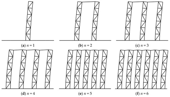
Figure 5.
The first vibration modes of a beams-racks combined system with n racks ().

Figure 6.
Simplified equivalent model in modal analysis ().
Based on the simplified equivalent model shown in Figure 6, modal analysis will be conducted to study the relationship between the periods of the rack TRk, the simplified structure TSS, and the real structure TRS under two different cases:
- (1)
- The total mass of the steel rack is constant, and the value of TRk is changed by varying the elasticity modulus ERk of the racks.
- (2)
- The stiffness of the rack is constant, and the period TRk of the rack varies through changing the total mass of the steel rack.
3.2. Period Relationship with Constant Rack Mass
Firstly, the mass ratio α of the rack mass to the total mass of the first floor in a real structure is calculated as:
The mass M1 of the first floor of the main structure is 8.1646 × 10⁴ kg. The mass m is firstly taken as 1.3607 × 10⁴ kg, with which the mass ratio is = 0.5, i.e., the mass of the first floor of the main structure is equal to the total mass of the racks.
Modal analysis is conducted for different real structures composed of different racks and main structures. The period TRk varies by changing the ERk of racks, and the period TSS0 varies by changing the elastic modulus EC of columns. It should be emphasized that varying the period TSS0 will consequently change the period TSS of the simplified structure in Figure 2c. Since the simplified structure is used in the current aseismic design, TSS can be used directly instead of TSS0 in MA1 and MA2 in this section.
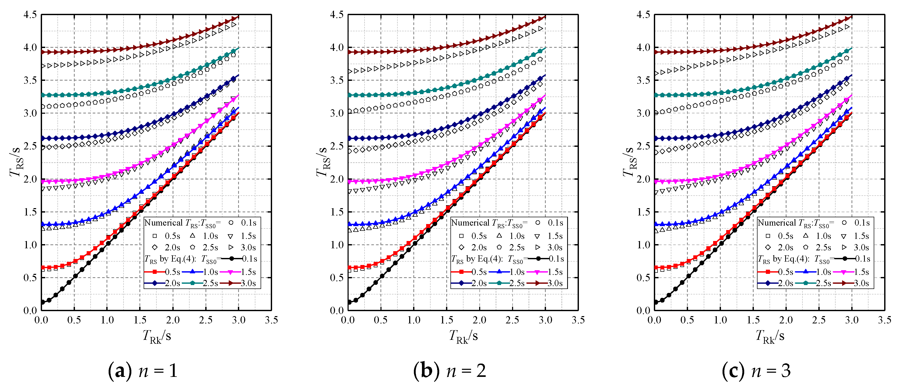
In MA1, TSS changes continuously (0.02, 0.04, ···, 2.98, 3.0 s) while TRk remains constant (TRk = 0.1, 0.5, 1.0, 1.5, 2.0, 2.5, 3.0 s, respectively). Under this condition, modal analysis is conducted on a total of 1050 real structures. Taking the simplified structure period TSS as the abscissa, seven TRS–TSS curves corresponding to the seven TRk are obtained in Figure 7a.
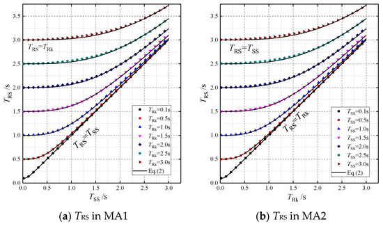
Figure 7.
Period relationships between three periods with a constant rack mass (, α = 0.5).
In MA2, TRk changes continuously (0.02, 0.04, ···, 2.98, 3.0 s) while TSS remains constant (TSS = 0.1, 0.5, 1.0, 1.5, 2.0, 2.5, 3.0 s, respectively). Under this condition, modal analysis is conducted on a total of 1050 real structures. Taking the period TRk as the abscissa, seven TRS –TRk curves corresponding to the seven TSS are obtained in Figure 7b.
From the curves in Figure 7a, it can be seen that for different TRk, each TRS–TSS curve starts at TRS = TRk and gradually increases to the straight line of TRS = TSS with the increase of TSS. For = 0.1 s, the curve is basically coincident with this straight line. The curves in Figure 7b obtained in MA2 assume a similar pattern: each TRS curve starts at TRS = TSS and gradually increases to the straight line of TRS = TRk with the increase of TRk.
As the effects of TSS and TRk on TRS are mathematically the same, the relationship between the three periods can be accurately expressed by Equation (2), which is obtained according to the least squares method. The comparison between the numerical results and Equation (2) is also presented in Figure 7. The comparison shows that the maximum deviation is only 1.0%, so Equation (2) has excellent accuracy for both MA1 and MA2.
The mass ratio α is constantly equal to 0.5 in this analysis procedure, and α is not considered as a variable that may affect the relation between the three natural periods. Therefore, the role of α will be addressed through parametric studies in the rest of this section.
Firstly, the mass m is set to be m = 5.4431 × 10⁴ kg, giving the mass ratio α = 0.8 and indicating that the mass of the rack is four times the mass M1. Similarly, the modal analysis in MA1 and MA2 is conducted to calculate the TRS–TSS and TRS–TRk curves, and the results are given in Figure 8. The curves in Figure 8 have similar shapes to those in Figure 7, but the fitting equation according to the least squares method is Equation (3), which is slightly different from Equation (2). The comparison between numerical results and Equation (3) is also given in Figure 8 and the maximum deviation is only 0.8%.
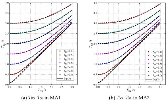
Figure 8.
Period relationships between three periods with a constant rack mass (, α = 0.8).
It can be concluded from Equations (2) and (3) that the relationship between TRk, TSS, and TRS for any value of α can be expressed in the form of:
where the power exponent ξ is dependent on the mass ratio α.
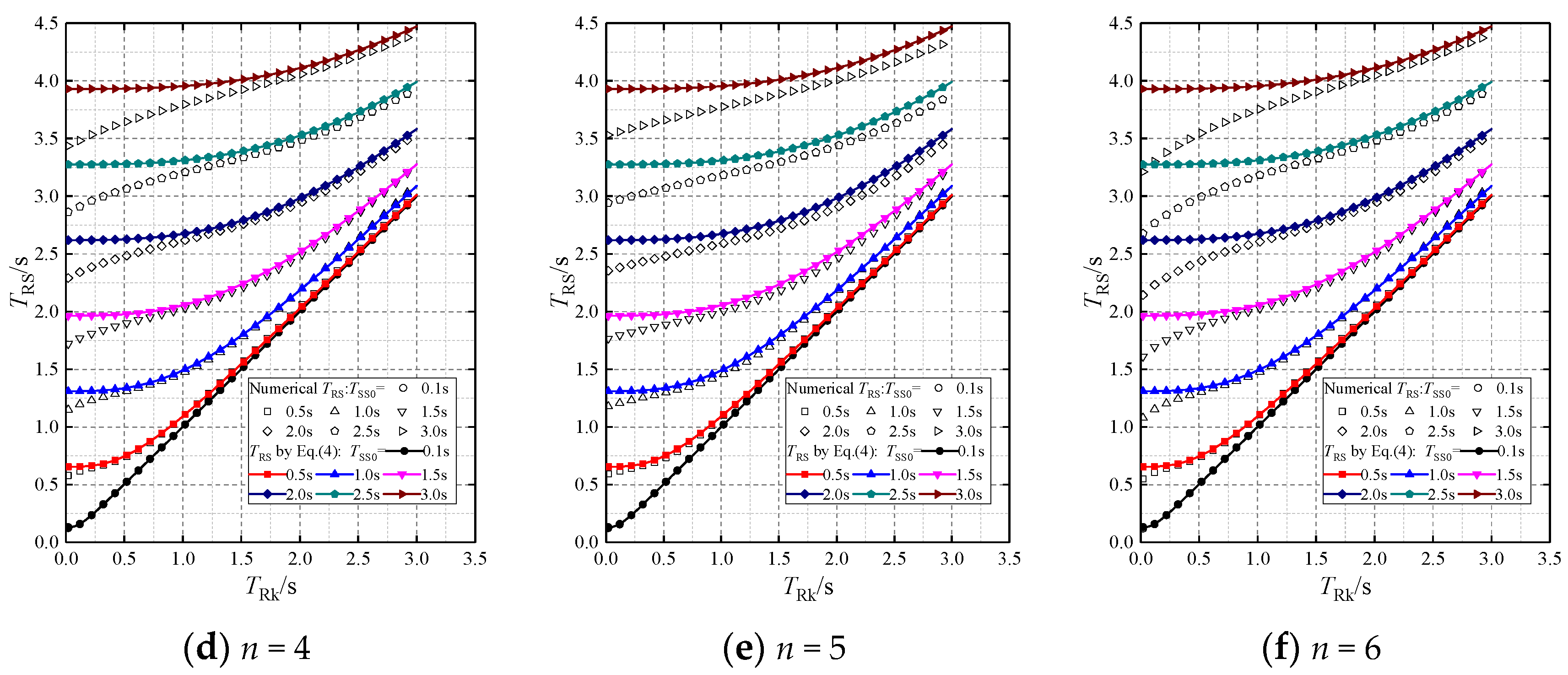
To further determine the expression of ξ as a function of α, α is set to 0.1, 0.2, 0.3, 0.4, 0.6, 0.7, and 0.9 in MA1 and MA2. Due to the symmetry of the results in MA1 and MA2, only the TRS–TRk curves obtained in MA2 with different values of α are plotted in Figure 9. Meanwhile, Equation (4) is also plotted in all the subfigures of Figure 9 using the best fitting values of ξ (shown in the notation of each subfigure). The TRS–TRk curves with α = 0.9 are no longer given and the power exponent is ξ = 2.35. The maximum deviations between Equation (4) and the numerical results in Figure 9a–f are 0.94%, 1.07%, 1.08%, 0.92%, 0.96%, and 0.97%, respectively.

Figure 9.
Period relationships with a constant rack mass (, α = 0.1, 0.2, 0.3, 0.4, 0.6, 0.7).
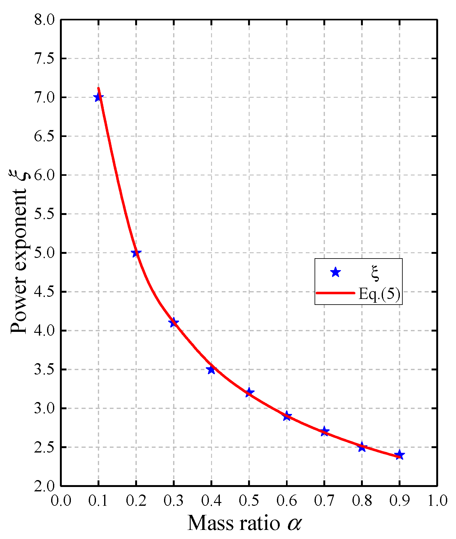
According to the results shown in Figure 7, Figure 8 and Figure 9, the relationship between the power exponent ξ and the mass ratio α is concluded as plotted in Figure 10, and the empirical expression obtained by the least squares method is proposed as Equation (5). The maximum deviation is only 1.2%.
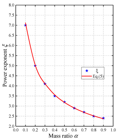
Figure 10.
The relationship between the power exponent ξ and the mass ratio α.
Therefore, in the case of infinitely rigid first-floor beams (), if the total mass of racks on the first floor of the main structure is given, the mass ratio α can be determined and subsequently the power exponent ξ is available in Equation (5). Next, the period TRS of the real structure can be determined by Equation (4). Therefore, when the simplified structure is used for analysis in design practice, Equations (4) and (5) can be used to calculate TRS to consider the difference between TRS and TSS in the simplified method.
3.3. Period Relationship with Constant Rack Stiffness
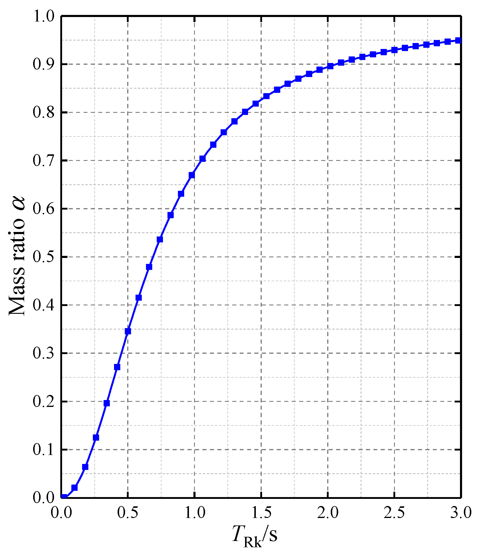
When the stiffness of the steel rack is determined (i.e., the elastic modulus ERk is constant), but the total mass of the rack is uncertain, the period TRk of the rack will vary through changing the mass of the rack. The constant elastic modulus ERk of the rack is determined following the principle that TRk = 3.0 s when the mass ratio α is 0.95. With the known ERk, TRk is 0.158 s when α = 0.05. Similarly, as TRk changes continuously (0.02, 0.04, ···, 2.98, 3.0 s), the corresponding relationship between α and TRk can be shown in Figure 11. It can be seen that the constant ERk obtained by this principle can make the mass ratio α reasonably distributed in the range of 0~0.95.
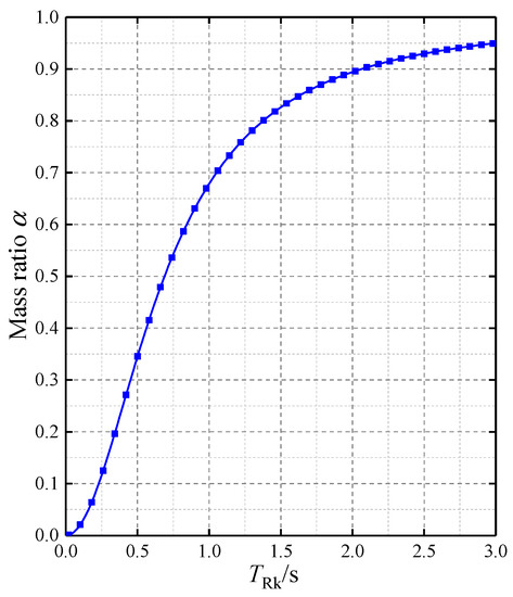
Figure 11.
The relationship between TRk and the mass ratio α.
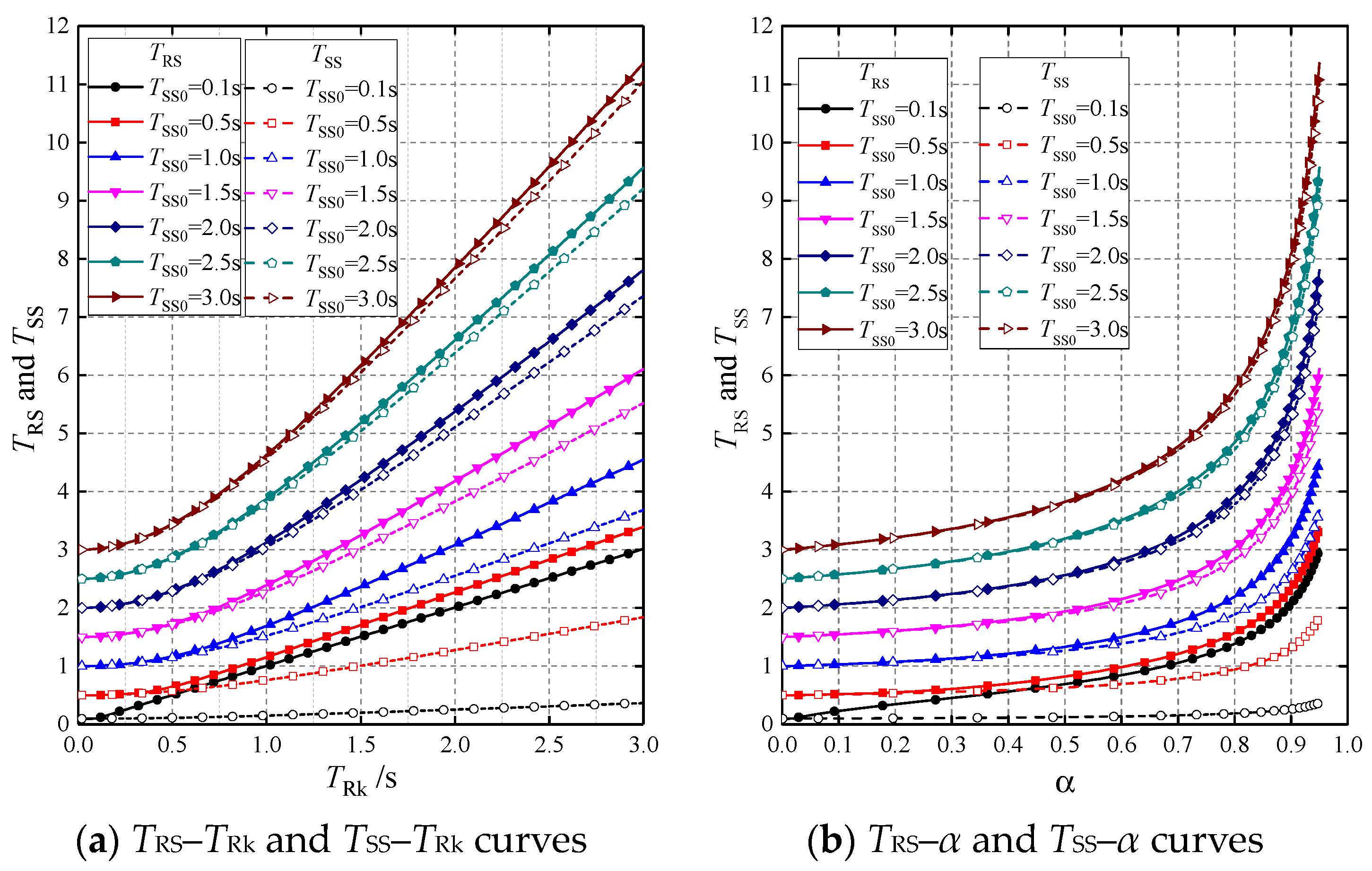
For the calculation models in Figure 2, the period TSS of the simplified structure changes with the change in mass of the racks. The modal analysis is conducted on both the simplified structures and the real structures according to MA2, in which the TRk changes continuously (0.02, 0.04, ···, 2.98, 3.0 s) while TSS0 remains constant (TSS0 = 0.1, 0.5, 1.0, 1.5, 2.0, 2.5, 3.0 s, respectively). The simplified equivalent models for real structures in Figure 6 are still used in modal analysis. Therefore, TRS–TRk and TSS–TRk curves can be obtained corresponding to the TSS0 of the seven periods of the main structures, as shown in Figure 12a. Meanwhile, according to the relationship between TRk and the mass ratio α (Figure 11), TRS–α and TSS–α curves are shown in Figure 12b.
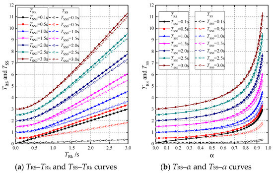
Figure 12.
TRS and TSS curves as a function of TRk and α with constant rack stiffness.
Since the rigidity of the rack is constant, Figure 12 shows that:
- (1)
- For the main structure with maximum rigidity (TSS0 = 0.1 s), TRS is basically the same as TRk, and TSS hardly changes with TRk and α;
- (2)
- For relatively flexible main structures (TSS0 ≥ 2.0 s), TRS is close to TSS and the maximum deviation is only 6.0%, which means the simplified structure can be used in place of the real structure in modal analysis;
- (3)
- With the decrease in TSS0, (i.e., the rigidity of the main structure is gradually increased relative to the rack), the difference between TRS and TSS becomes more obvious;
- (4)
- With the increase of TRk, the TRS–TRk and TSS–TRk curves gradually become straight lines, which means TRS and TSS are linearly related to TRk. Moreover, the difference between TRS and TSS gradually increases.
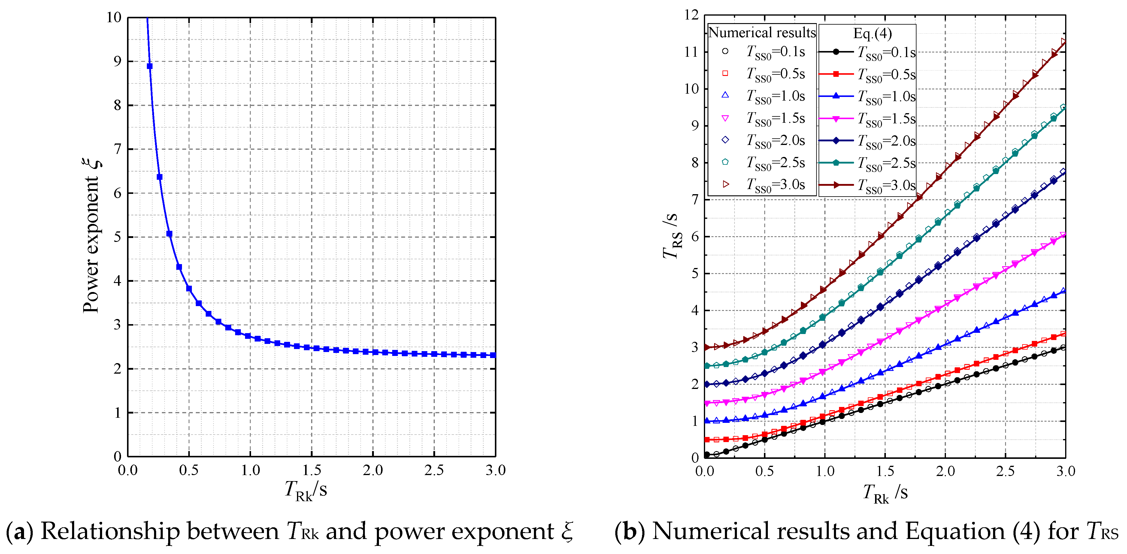
The numerical results of TRS and TSS in Figure 12 can also be used to validate Equation (4). Based on the corresponding relationship between TRk and α in Figure 11, the power exponent ξ in Equation (4) can be obtained by Equation (5), as shown in Figure 13a. Therefore, the periods TRS of real structures can be calculated using Equation (4) () and plotted in Figure 13b. The TRS–TRk curves obtained from Equation (4) are in good agreement with the numerical results, with a maximum deviation of 0.6%.
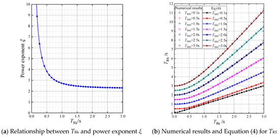
Figure 13.
Comparison of the numerical results and Equation (4) for TRS with changing rack mass ratio α ().
To conclude, the TRk–TSS–TRS relationship can be accurately expressed using Equations (4) and (5) when the influence of floor beam stiffness is not considered and the first-floor beams are assumed to be infinitely rigid ().
4. The Period Relationship with Finite Beam Stiffness
The TRk–TSS–TRS relationship, Equation (4), is based on the assumption that the first-floor beams are assumed to be infinitely rigid (). However, the floor beam stiffness is finite in practice. Therefore, the influence of floor beam stiffness on the TRk–TSS–TRS relationship will be taken into account in this section.
The real structures with 1–6 steel racks installed on the first floor, as shown in Figure 14, are used in the modal analysis. For the main structure shown in Figure 2b, because the frame beam is normally heavy in such warehouses, the period TSS0 is mainly controlled by the elastic modulus of columns (EC). The elastic modulus of beams (EB) is always equal to EC. The variation of TSS0 is realized by changing EB and EC simultaneously, and the ratio of beam-to-column stiffness is constant at 0.41 according to the given sections of the main structural components in Table 1.
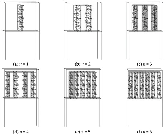
Figure 14.
Real structures with n racks on the first floor.
Considering that Equation (4) is related to the mass ratio α, in order to more directly show the influence of the number of racks, the mass of racks can be prescribed as follows: The total mass of racks is prescribed (the mass ratio α is constant), and it is uniformly distributed to different numbers (n = 1, 2, 3, 4, 5, and 6) of racks on the first floor, ensuring the same period for each rack. Since the total mass of racks in engineering practices would not be very small, the mass ratio α is assumed to be in the range of 0.4–0.9.
For each constant mass ratio α, modal analysis is carried out for the six real structures in Figure 14 and simplified structures according to MA2, in which TRk changes continuously (0.02, 0.04, ···, 2.98, 3.0 s) while TSS0 remains constant (TSS0 = 0.1, 0.5, 1.0, 1.5, 2.0, 2.5, 3.0 s, respectively).
It should be noted that when the TSS0 remains constant, the changing α will consequently change the period TSS of the simplified structure in Figure 2c. With different values of α, the corresponding TSS values are listed in Table 2.
Table 2.
Period TSS of simplified structures with different values of α.
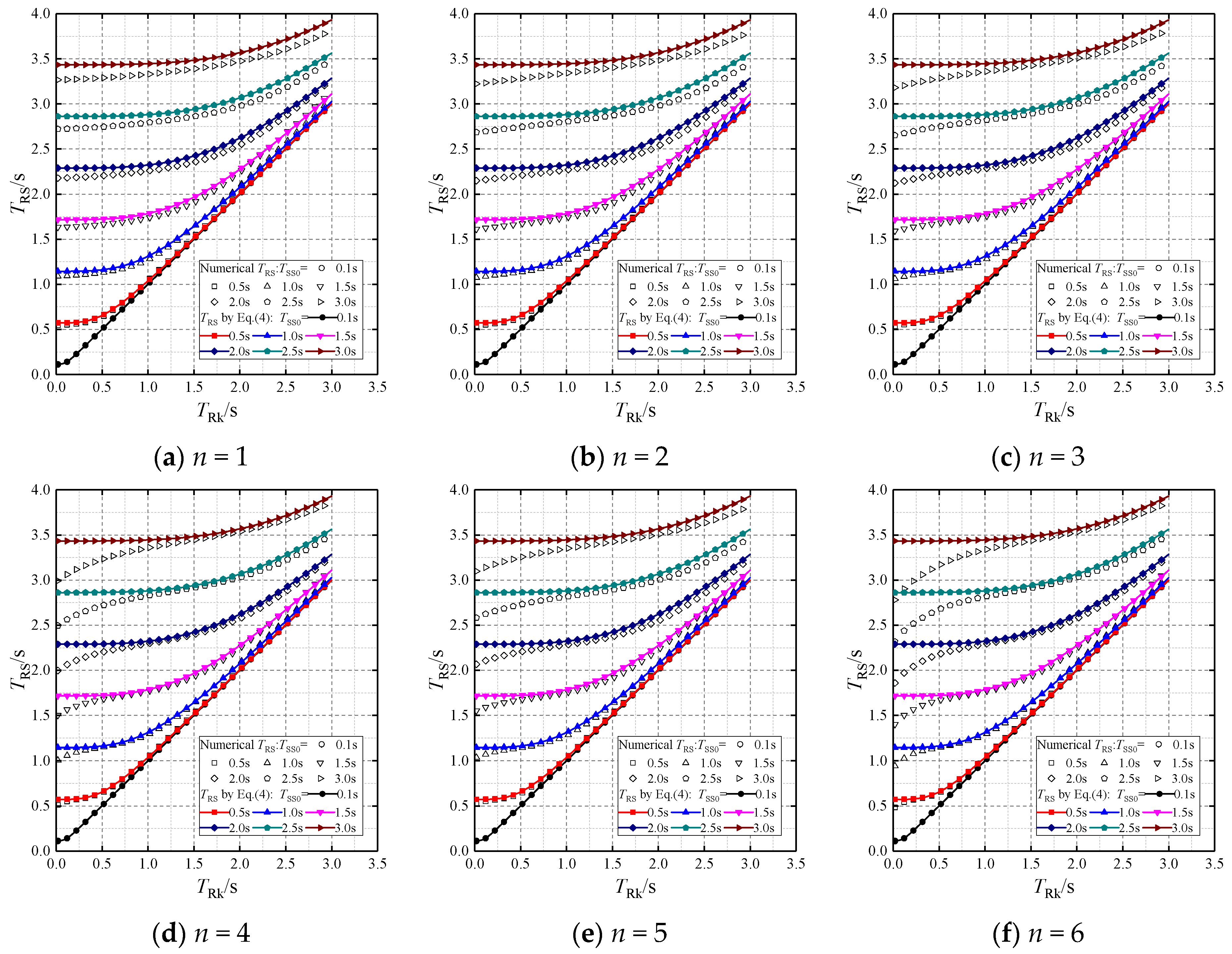
Firstly, modal analysis on the six real structures (Figure 14) with different TSS0 and TRk is conducted to obtain the corresponding TRS when the mass ratio α is 0.4, as shown in Figure 15. For comparison, the TRS can be calculated using Equation (4) (), in which the period TSS can be determined in Table 2 with the given mass ratio α and TSS0. The power exponent ξ is calculated by Equation (5) (). Therefore, the calculation results of Equation (4) are the same for the six real structures in Figure 14, as shown in Figure 15. It can be seen that: when TRk > 1.0 s, the maximum deviation of TRS between the numerical results and Equation (4) is only 3.4%. When the racks are nearly rigid (TRk = 0.02 s) and TSS0 = 3.0 s, the maximum deviation is 18.9%.
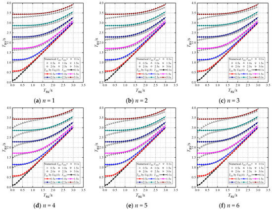
Figure 15.
Numerical results and Equation (4) for TRS with finite beam stiffness (α = 0.4, ξ = 3.558).
Similarly, for α = 0.6 and 0.8, the numerical results of TRS are plotted in Figure 16 and Figure 17, and TRS–TRk curves obtained from Equation (4) with and are also plotted in Figure 16 and Figure 17 for comparison, respectively. It can be seen from Figure 16 that when TRk > 1.0 s, the maximum deviation of TRS between the numerical results and Equation (4) is only 4.4%. When the racks are nearly rigid and TSS0 = 3.0 s, the maximum deviation is 18.2%. For Figure 17, the maximum deviation is 6.6% when TRk > 1.0 s, while it increases to 17.0 when the racks are nearly rigid and TSS0 = 3.0 s.
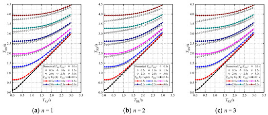
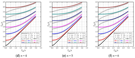
Figure 16.
Numerical results and Equation (4) for TRS with finite beam stiffness (α = 0.6, ξ = 2.905).
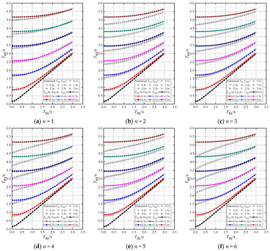
Figure 17.
Numerical results and Equation (4) for TRS with finite beam stiffness (α = 0.8, ξ = 2.516).
Based on Figure 15, Figure 16 and Figure 17 illustrating the influence of finite floor beam stiffness, the following conclusions can be drawn:
- (1)
- When TRk > 1.0 s, the numerical and theoretical (Equation (4)) results of TRS are in good agreement. Therefore, Equation (4) is still applicable.
- (2)
- When TRk < 1.0 s, the numerical results of TRS are shorter than those obtained from Equation (4).
- (3)
- With the increase of the rack number n, the difference between the numerical results and Equation (4) becomes more obvious, especially in the cases of longer TSS0. Maximum differences occur when n is 6, TSS0 = 3.0 s, and TRk < 1.0 s, in which case the racks are relatively rigid and the floor beams are flexible.
For practical engineering, the warehouse height can reach 20–25 m, and the story height is about 10–12 m. The steel racks are essentially very tall and flexible structures, and many racks supporting heavy pallet units have periods of 1.5–2.5 s in the CA direction. When multiple racks with periods of 1.5–2.5 s are placed on the first floor of the two-story real structure, most of the mass of the real structure comes from the racks and the period of the real structure will be longer than 1.0 s. For these cases, Equations (4) and (5) proposed in this article are applicable in the design practice.
Although these differences are almost acceptable in practical engineering, the reasons for the differences should be further analyzed in the following part to include them in practice.
5. The Interaction between Racks and the Main Structure
Based on the above analysis, the reason for the difference between Equation (4) and the numerical results is that the interaction between racks and the main structure (mainly floor beams) has been neglected in Equation (4). In the following, the influence of the racks on the main structure and the influence of the main structure on the racks are studied by constructing different analysis models.
5.1. Influence of the Main Structure on Racks
The influence of the main structure on racks on the first floor is mainly reflected in the influence of the rigidity of the first floor beams as the elastic supports of the racks. In the case of infinite beam stiffness (), all racks in the six combined systems (Figure 4) have the same first vibration mode in the CA direction, i.e., , as seen in Figure 5
When the floor beam stiffness is finite, however, the period . Therefore, the different beams-racks combined systems given in Figure 4 are selected to study the influence of the main structure on the racks. The elastic modulus EB of the beams will be taken as the elastic modulus of the members when the period TSS0 of the main structure is 0.1, 0.5, 1.0, 1.5, 2.0, 2.5, and 3.0 s, respectively, ensuring that TSS0 basically covers the range of 0.02 s–3.0 s. For example, when TSS0 is 1.0 s, the elastic modulus of beams is denoted as EB (TSS0 = 1.0 s).
The real structures with 1–6 steel racks installed on the first floor, as shown in Figure 14, are used in the modal analysis. For the main structure shown in Figure 2b, the period TSS0 is mainly controlled by the elastic modulus of columns (EC). The elastic modulus of beams (EB) is always equal to EC, and thus, the variation of TSS0 is realized by changing EB and EC. The ratio of beam-to-column stiffness ib/ic is constant at 0.41, according to the given sections of main structural components in Table 1.
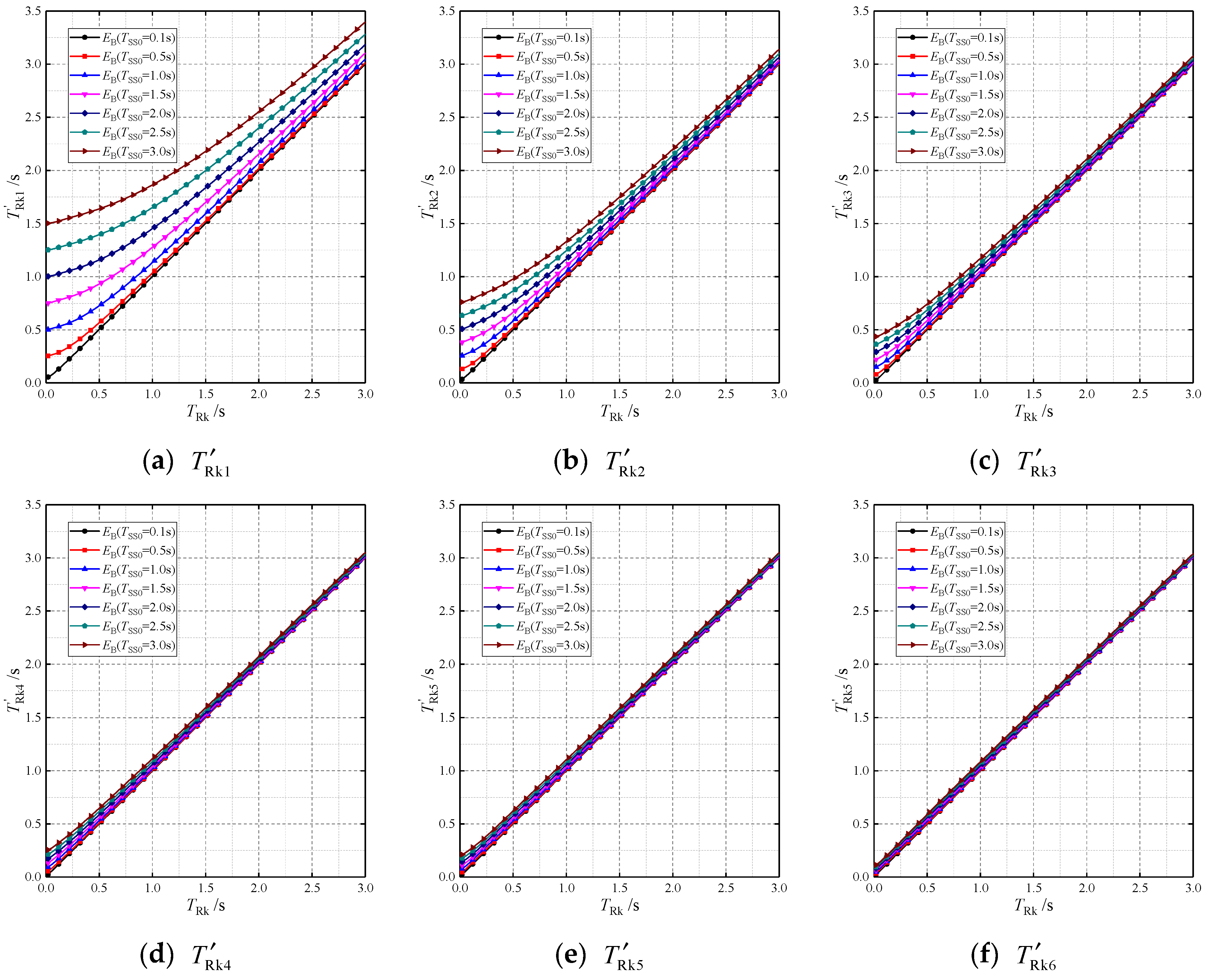
Therefore, the mass ratio is set as α = 0.6 and the TRk changes continuously (0.02, 0.04, ···, 2.98, 3.0 s) for each elastic modulus EB (TSS0 = 0.1, 0.5, 1.0, 1.5, 2.0, 2.5, 3.0 s). The modal analysis is conducted for the six different beams-racks combined systems to obtain corresponding , and the relationship between and TRk is shown in Figure 18.
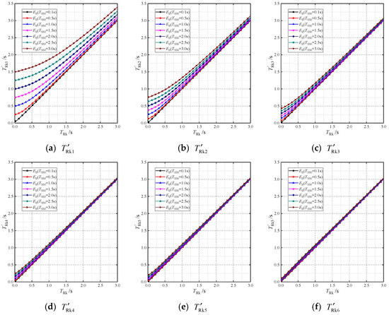
Figure 18.
The period of the six different beams-racks combined systems with finite EB (α = 0.6).
It can be shown in Figure 18 that when the elastic modulus EB of the beams results in a main structure period of TSS0 = 0.1 s, meaning that the first-floor beams are nearly rigid, is closed to TRk.
For the case of the rack number n = 1, the difference between and TRk increases gradually with the decrease in EB, which means that the restraint of the beams to the racks decreases. However, as n increases, the differences become insignificant, e.g., when n = 6, Figure 18f shows that and TRk are almost the same, which means the restraint to the racks is nearly rigid and the effect of beam stiffness EB is small.
For the calculation of of the combined system shown in Figure 19a, a simplified equivalent method (Figure 19b) can be introduced: the connecting bars between racks at their tops ensure that all racks in the combined system vibrate in the same shape, and the floor beams act as the elastic rotational restraint for the racks under horizontal vibration. The period is written out by considering the original system as the two sub-systems set up in series:
in which T0 is the period when the racks are integrated as one infinitely rigid rack which is supported by a rotational spring with a stiffness of KZ. Therefore, T0 physically represents the rotational restraint of the floor beams to the racks. TRk is the period of the rack fixed on the ground.
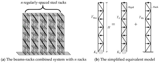
Figure 19.
The beams-racks combined systems and the simplified equivalent model.
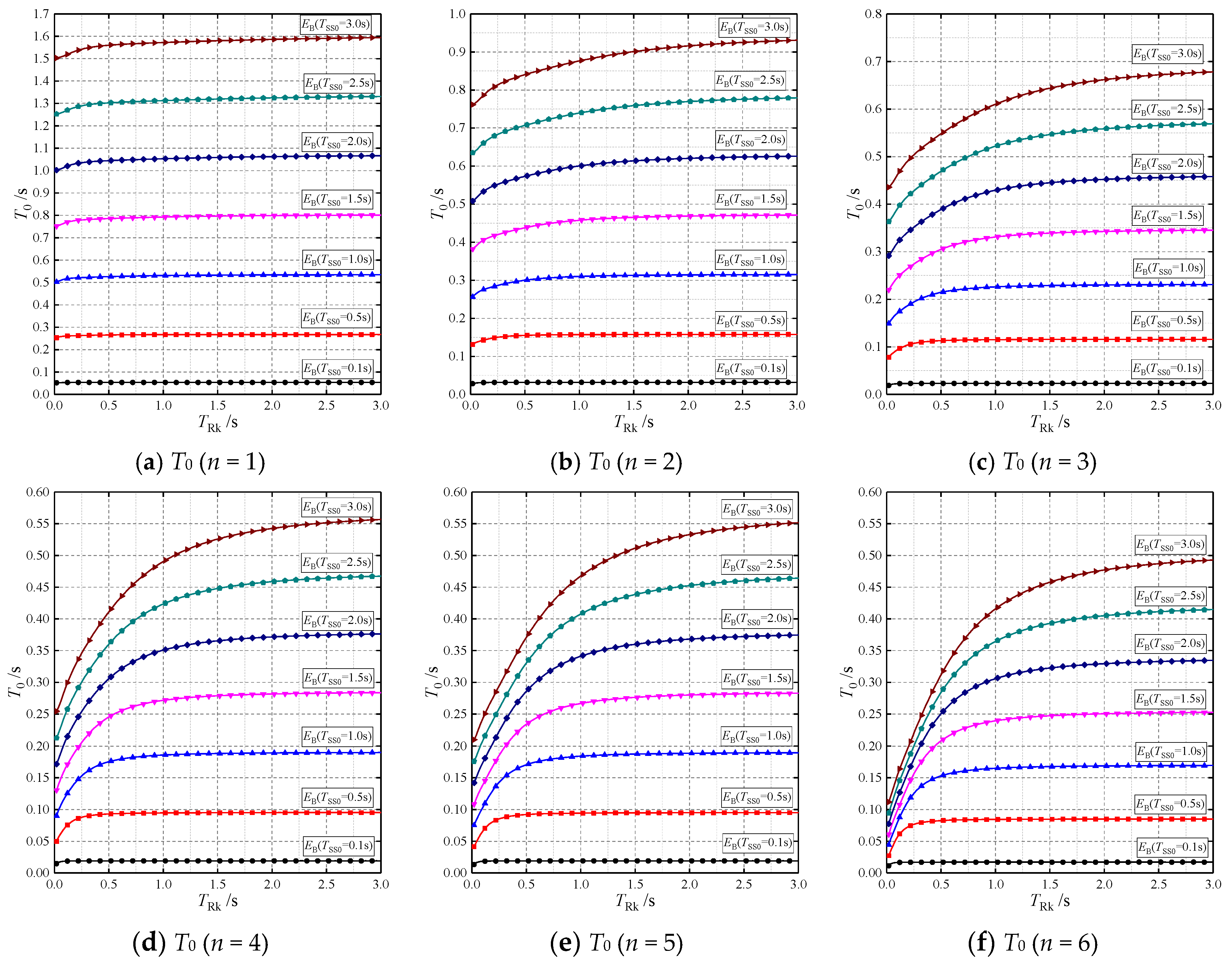
Based on this simplified equivalent method, referring to the values of in Figure 18 (α = 0.6), the period T0 for different numbers of racks can be determined using Equation (6) () and plotted in Figure 20.
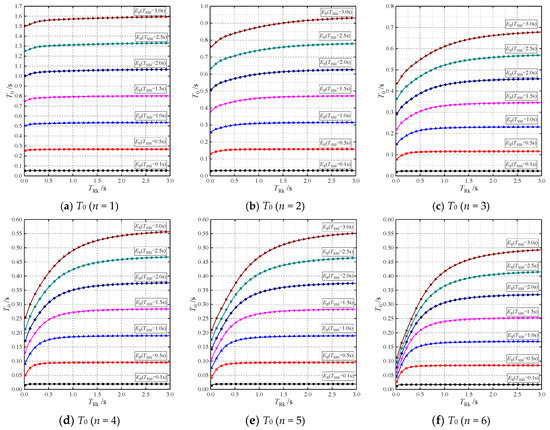
Figure 20.
The period T0 of the six different beams-racks combined systems with finite EB (α = 0.6).
T0 decreases with the increase in floor beam stiffness (EB), as shown in Figure 20, and TRS becomes closer to that obtained using Equation (4), which can also be concluded from Figure 16.
By comparing the curves with TSS0 = 3.0 s in Figure 20a–f, it is found that:
- (1)
- In the case of n = 1, T0 approaches the maximum value of 1.6 s, which means that the restraint of the beams to the racks is relatively minimal. The difference between and TRk also reaches the maximum. However, as illustrated in Figure 16a, the numerical results of TRk are approximated to those obtained from Equations (4) and (5) with good accuracy.
- (2)
- In the case of n = 6, the maximum value of T0 is only 0.5 s and T0 decreases further in the short period range of TRk < 1.0 s, which means the difference between and TRk is small and the restraint of the beams to the racks is nearly rigid. However, as depicted in Figure 16a, the maximum difference of TRS between the numerical results and the prediction of Equation (4) occurs exactly within this range.
Therefore, in the period range of long TSS0 and short TRk in Figure 16, the differences between numerical results and Equation (4) are not due to the influence of the floor beams on the racks.
Comparing Figure 18 and Figure 20, it can be seen that such differences are basically consistent with the trend of T0 curves. Based on the simplified equivalent method for in Figure 19b, the decrease in T0 is due to the increase in KZ, which means the reversed rotational constraint of racks on the beams also increases gradually. Therefore, the differences of TRS between numerical results and Equation (4) are probably caused by the strengthening effect of the racks on the floor beam stiffness, which will be discussed in detail in the following.
5.2. Influence of Racks on the Main Structure
The racks may increase the stiffness of the first floor, and this can be studied using the new model shown in Figure 21. This modified model reserves the racks but integrates the total mass of the racks into the first floor of the real structure. This modified model is distinguished from the simplified structure in Figure 2c by taking into account the effect of the no-mass racks, so the period of this modified model is denoted by . Therefore, the analysis of the influence of the racks on the main structure can be obtained by comparing the periods of the simplified structure (TSS) with the periods of the modified model ().
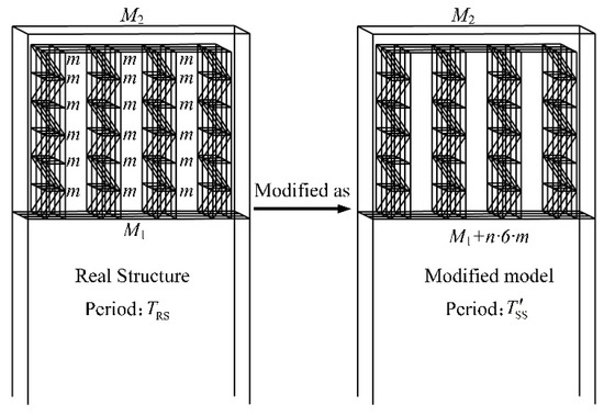
Figure 21.
The new modified model based on the real structure.
The analysis started with the case leading to the maximum difference in TRS between numerical results and Equation (4) in Figure 16, in which TSS0 = 3.0 s, n = 6, and α = 0.6. In this case, the period TSS is 3.93 s. The TRS obtained from Equation (4) () is larger than the numerical result, especially when TRk < 1.0 s.
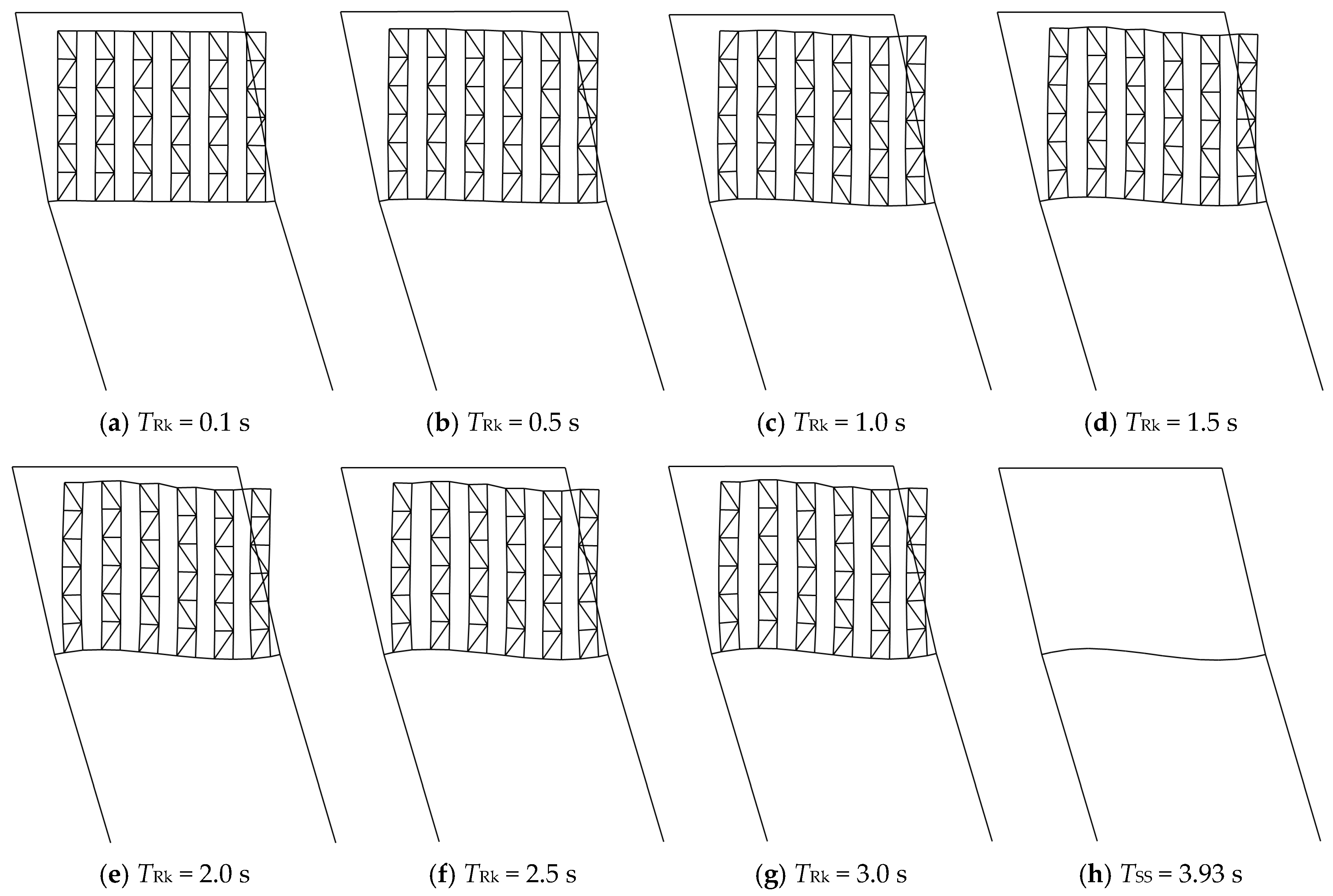
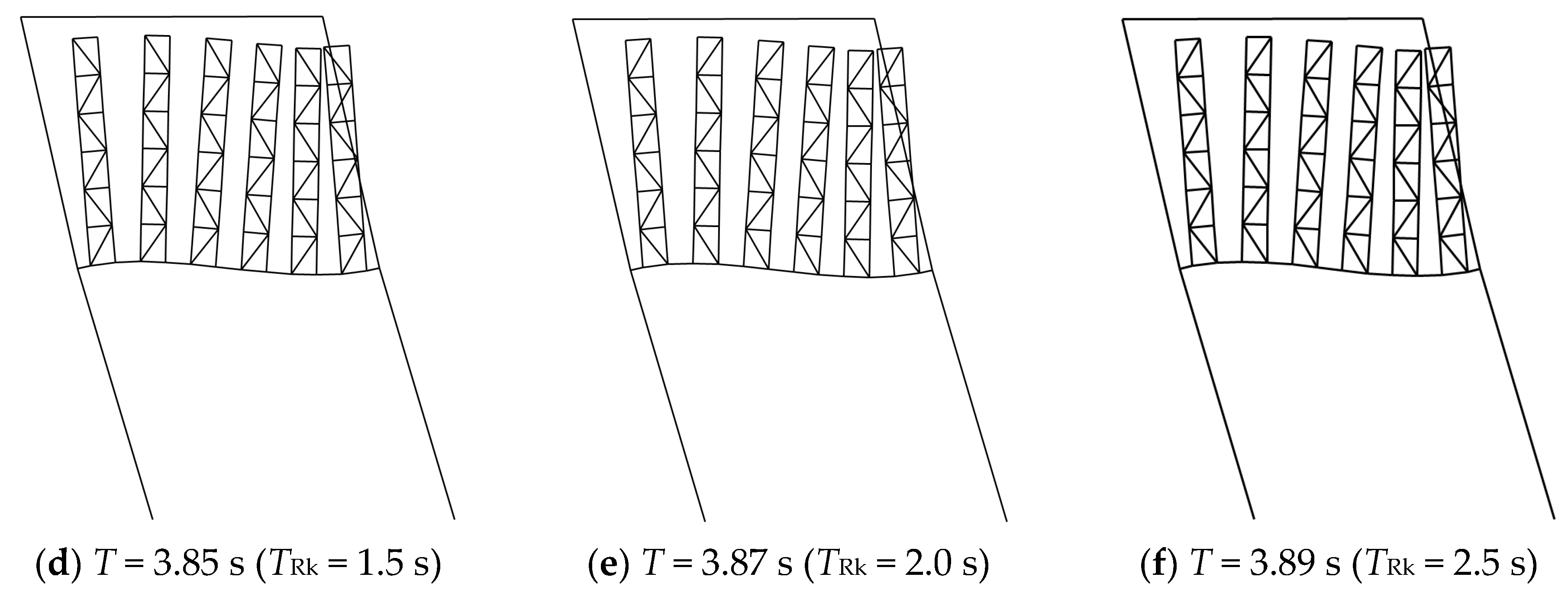
For the new modified model with no-mass racks in Figure 21, the influence of the different racks is included by setting different values of ERk corresponding to TRk = 0.1, 0.5, 1.0, 1.5, 2.0, 2.5, and 3.0 s. Modal analysis on modified models with these different racks is conducted. The obtained are listed in Table 3, and corresponding modal shapes are plotted in Figure 22a–f. For comparison, the modal shape of the simplified structure without racks (TSS = 3.93 s) is also given in Figure 22g.
Table 3.
Period of the modified model with no-load racks (n = 6, α = 0.6).

Figure 22.
The first modal shapes of modified models and simplified structures.
It is seen in Table 3 that is always shorter than TSS and the difference increases with the increase in the rack stiffness. Combined with Figure 22 for the first modal shape, it is found that with the increase in rack stiffness, the deflection amplitude of the floor beam in the vibrational mode becomes smaller. The specific deflection values of the first vibration amplitude are given in Table 3.
When TRk = 3.0 s, the racks have a small effect on the stiffness of the frame beam. The vibration amplitude of the frame beam is 92.3% of that in the simplified structure shown in Figure 22h with the corresponding = 3.88 and s = 0.99TSS. Thus, the vibration characteristics of the two models are almost identical. In this case, the value of TRS obtained from numerical results is basically equal to that obtained from Equation (4), as shown in Figure 16f.
On the other hand, when TRk = 0.1 s, the frame beam of the first floor is almost rigid, and the vibration amplitude is only 8% of the amplitude in the simplified structure, and = 3.29 and s = 0.837TSS. Therefore, the racks with high rigidity increase the stiffness of the floor beams and contribute to reducing the period of the simplified structure. However, in Equation (4) which represents the simplified design method, this strengthening effect has not been included in the simplified structure, thus a long TSS leads to a longer TRS obtained from Equation (4) than the numerical results, as shown in Figure 16f.
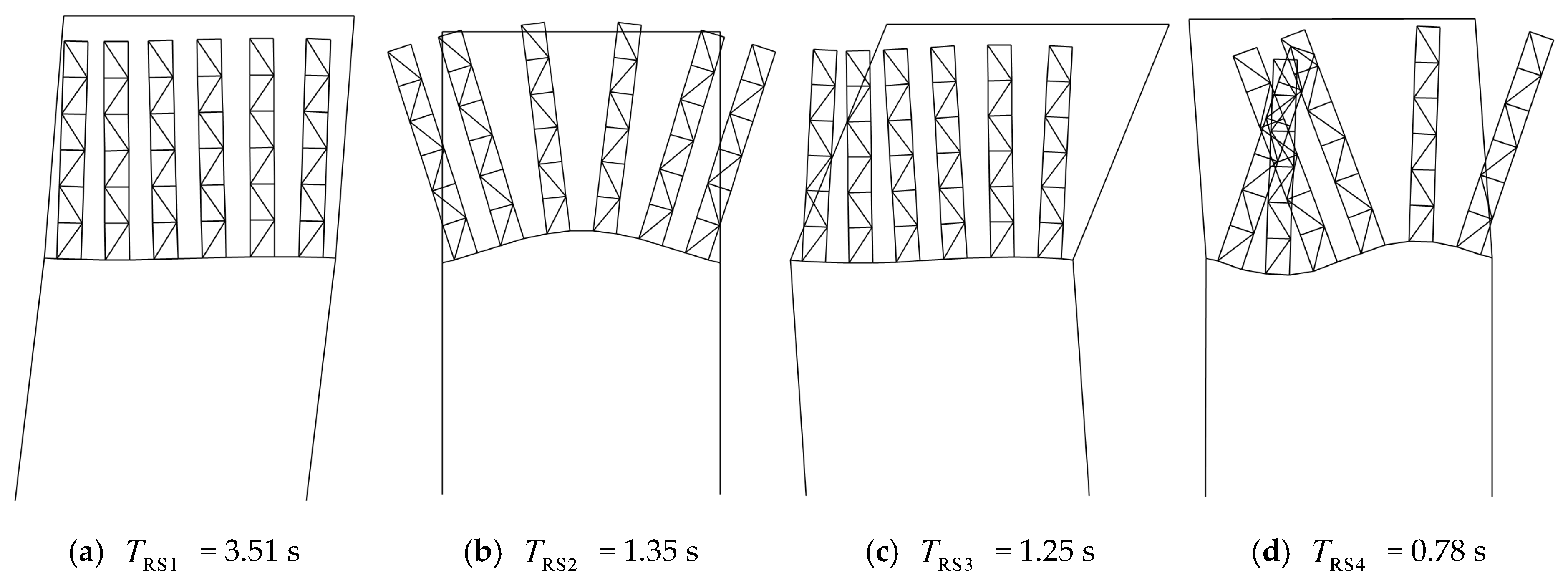
The role of the connecting bars between racks in this strengthening effect should also be addressed in this section. Modal analysis is conducted on the modified model in Figure 21, without connecting bars between the top of racks. Similarly, given TSS0 = 3.0 s and different values of ERk corresponding to TRk = 0.1, 0.5, 1.0, 1.5, 2.0, 2.5, and 3.0 s, the and the vibration amplitudes of frame beams are listed in Table 4. Meanwhile, the periods TRS of the seven real structures in Figure 16f are also listed. The first modal shape of the six modified models without connecting bars are shown in Figure 23.
Table 4.
Vibration characteristics of the modified model with/without connecting bars (n = 6, α = 0.6).
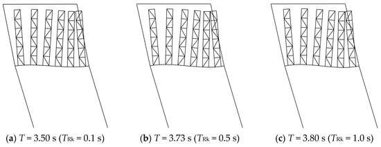
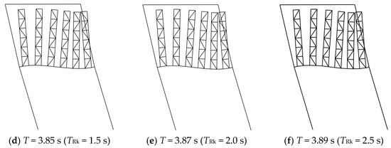
Figure 23.
The first periods and modal shapes of the modified models without connecting bars.
It is found in Table 4 that, when TRk > 1.0 s, the of the modified model with no-mass racks is not significantly affected by the top connecting bars. The modal shapes corresponding to different are quite similar, as shown in Figure 23. However, when TRk < 1.0 s, the strengthening effect of the connecting bars on the frame beams cannot be ignored.
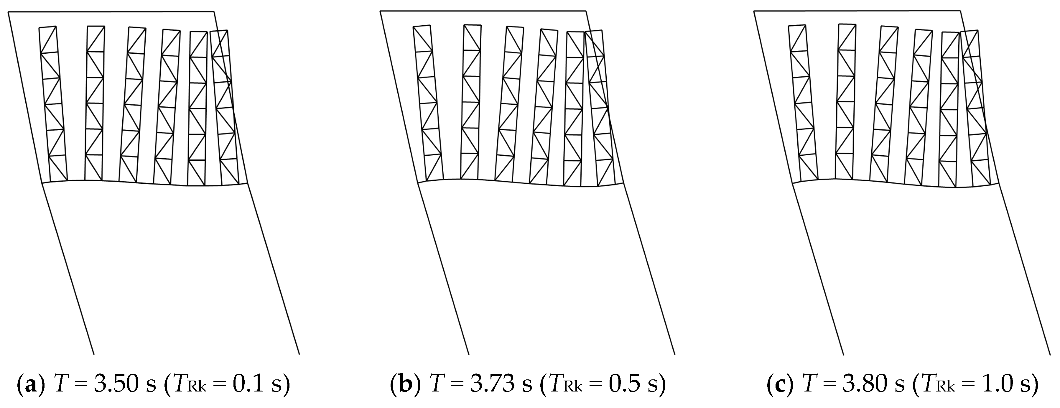
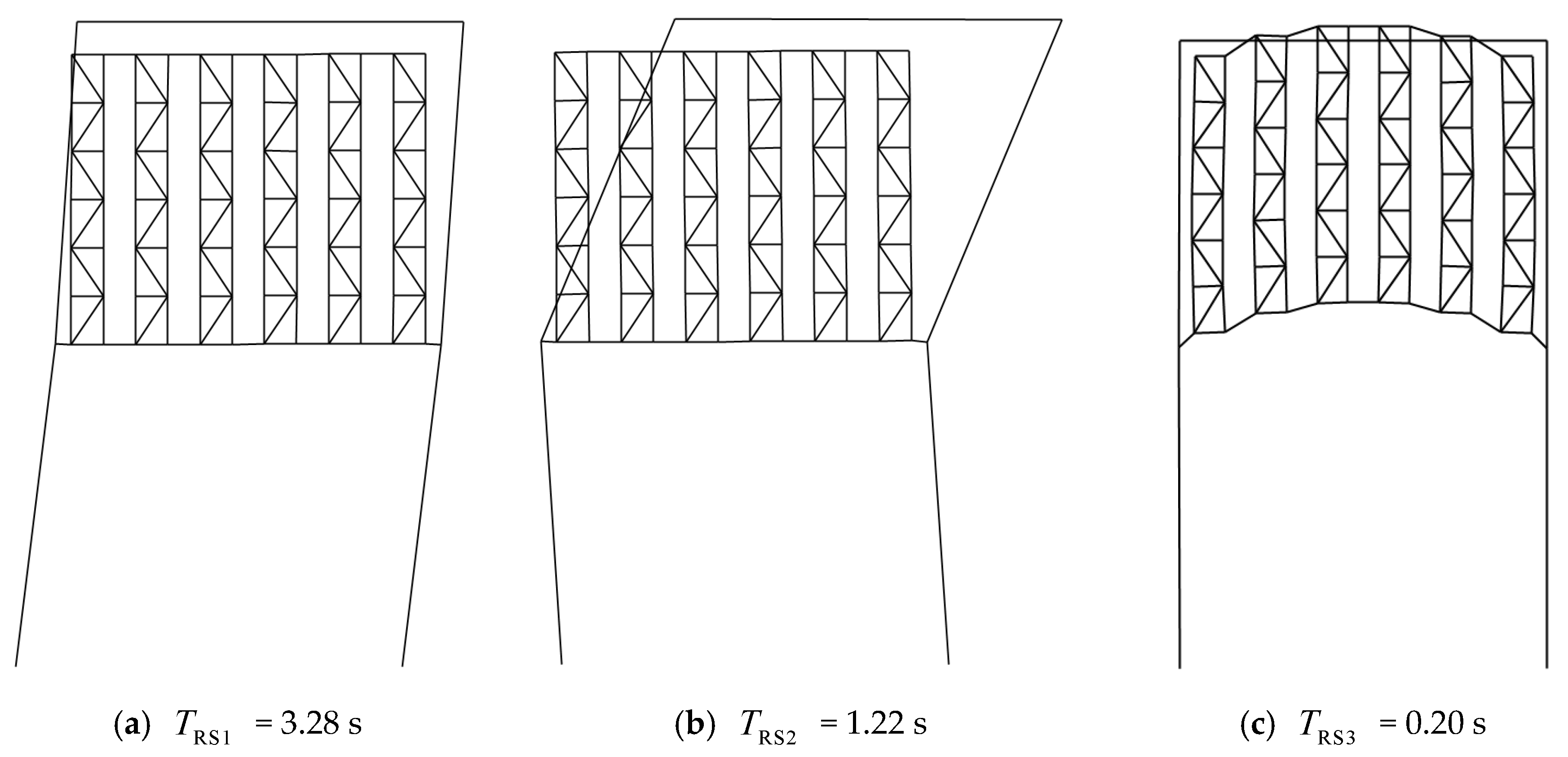
To further analyze the effect of connecting bars on the real structure, the real structure with TSS0 = 3.0 s and TRk = 0.1 s is selected, and modal analysis is conducted on real structures with and without the top connecting bars, respectively. The modal shapes of this real structure without connecting bars are plotted in Figure 24, and those of real structures with connecting bars are plotted in Figure 25.

Figure 24.
The periods and modal shapes of the real structure without connecting bars.
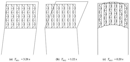
Figure 25.
The periods and modal shapes of the real structure with connecting bars.
It can be seen that the first modal shapes are similar with or without bars, and the connecting bars reduce the first natural period of the real structure by 6.6%. The top connecting bars change the second and higher-order vibration modes.
Therefore, the strengthening effect of the racks on the beams is partly due to the high rigidity of the racks and connecting bars. The connecting bars eliminate the local vibration modes between racks and ensure that the modes of all racks are laterally consistent. As a result, the real structure will vibrate as an integrity.
Thus, Equation (4) can be modified by replacing TSS with :
in which the power exponent ξ corresponding to the mass ratio α can be obtained by Equation (5).
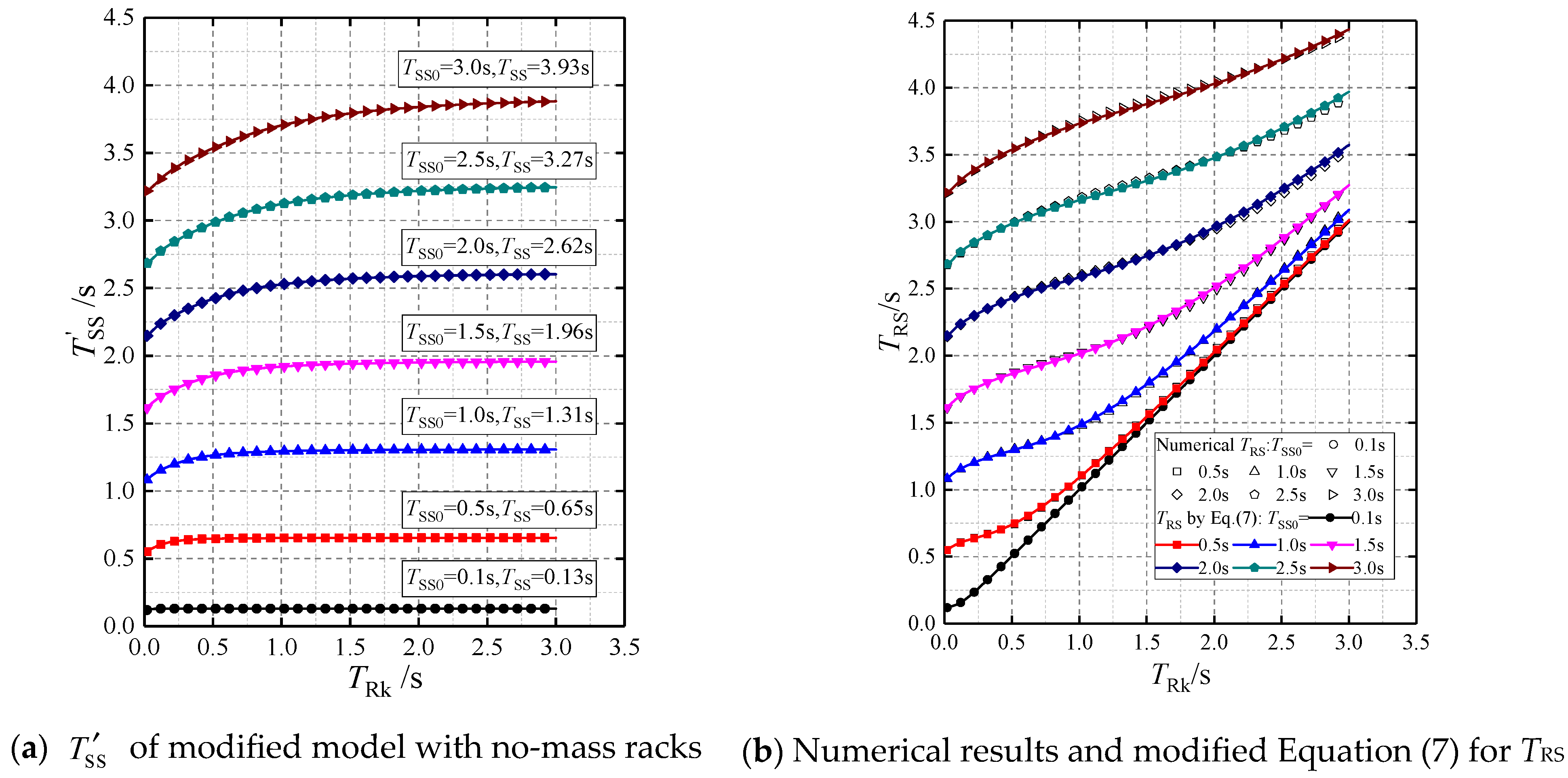
In order to validate Equation (7), modal analysis is conducted on the modified model shown in Figure 21 according to MA2, in which TRk changes continuously while TSS0 remains constant. The obtained are plotted in Figure 26a, and the corresponding TSS are also given. Therefore, the TRS can be calculated by Equation (7) to be compared with the numerical results, as shown in Figure 26b. It can be seen that they are in good agreement and the maximum deviation is only 1.1%.
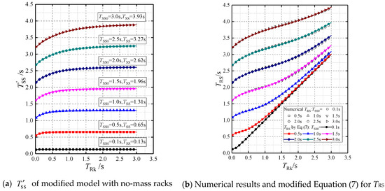
Figure 26.
of the modified model and a comparison between numerical TRS and modified Equation (7) (n = 6, α = 0.6).
In addition, it is also indicated in Figure 26a that the difference between and TSS due to the strengthening effect of racks on floor beams is significant only in the cases where the racks are relatively rigid compared with the first floor of the main structure. With an increase in floor stiffness, the difference becomes smaller. For TSS0 = 3.0 s, when TRk = 0.5 s, = 3.53 and s = 0.9, and the deviation is 10% while it was only 5% when TRk = 1.06 s. When TRk continues to increase, the influence of steel racks on the main structure floor can be neglected.
For convenience of calculation, this type of strengthening effect can be considered by multiplying the obtained period TRS by a reduction factor of 0.8–0.95, similar to the effect of infilled interior walls on the period of a frame. When TRk > 1.0 s, a reduction factor of 0.95 can be used. A reduction factor of 0.8 should be used when the racks are nearly rigid and TSS0 is approaching 3.0 s. However, these cases rarely happen in practice, as the rigidity of the first floor is generally large as they are required to support multiple fully distributed and fully loaded racks. As the steel racks are essentially very tall and flexible structures, many racks supporting heavy pallet units have periods TRK ≥ 1.5 s in the CA direction.
Therefore, in the design practice of a real structure with racks on the first floor, the simplified structure period TSS can be obtained by concentrating the mass of all racks into the first floor of the main frame. Combined with the characteristics of racks, the period TRS of the real structure can be accurately predicted by Equations (4) and (5), with a suitable account of the stiffening effect of racks on beam stiffness by a period reduction factor of 0.8–0.95.
6. Summary and Conclusions
In this paper, a two-story steel frame is selected as the main structure. Steel racks with different masses, stiffnesses, and quantities are placed on the first floor of the main structure to form different real structures (RSs). The corresponding simplified structures (SS) are frames with the mass of steel racks concentrated on the first floor of the main structure. Modal analysis is performed to analyze the dynamic characteristics of RS and SS in the CA direction. The periods TRS of the RSs and TSS of the SSs are calculated, and the interaction between regularly spaced steel racks and the main structure is studied. The following conclusions can be drawn based on the results:
- (1)
- When the first-floor beams are assumed to be infinitely rigid (), the connecting bars at the top of the racks ensure that all racks vibrate in the same first vibration mode. The number and arrangement of racks have no influence on the modal shape of the real structure.
- (2)
- When , the relationship between the period TRk, TSS, and TRS can be accurately expressed by Equation (4): , where the power exponent . The influence of the mass ratio α is considered, so that the relationship is applicable for the mass ratio α changing in the range of 0~1.0.
- (3)
- The influence of the finite floor beam stiffness of the main structure on the relationship between the period TRk, TSS, and TRS is taken into account. When TRk > 1.0 s, TRS predicted by Equation (4) are in good agreement with the numerical results. However, with the increase of the rack number n, the difference becomes more obvious, especially for the cases of long TSS0 with relatively rigid racks and flexible floor beams.
- (4)
- With finite beam stiffness, the influence of the main structure on the racks is reflected in the influence of the rigidity of the first-floor beams as the elastic supports of the racks. Different beams-racks combined systems are selected to study the influence of the main structure on the racks. The period of the beams-racks combined system is always greater than TRk, and the difference increases gradually with the decrease in beam stiffness, but with the increase in the number of racks (which is always the case in practice), the difference is becoming non-significant and negligible.
- (5)
- With finite beam stiffness, the strengthening effect of the racks on the stiffness of the floor beams of the main structure is studied by constructing a new modified model, which is distinguished from the simplified structure by taking into account the effect of the no-mass racks. The racks with high rigidity and the continuous inter-connecting bars at the tops of the racks increase the stiffness of the floor beams and contribute to reducing the period of the simplified structure. The inter-connecting bars eliminate the local vibration modes between racks and ensure the modes of all racks are laterally consistent. As a result, the real structure will vibrate as an integrity.
- (6)
- This strengthening effect leads to a shorter period TRS than that predicted by Equations (4) and (5), especially in the cases where the racks are relatively rigid compared with the first floor of the main structure. This effect can be considered by multiplying the obtained period TRS by a reduction factor of 0.8–0.95, similar to the effect of infilled interior walls on the period of a frame, but these cases rarely happen in practice.
Therefore, in the design practice of a real structure with racks on the first floor, the simplified structure period TSS can be obtained by concentrating the mass of all racks on the first floor of the main structure. Combined with the characteristics of racks, the period TRS of the real structure can be accurately predicted by Equations (4) and (5), with the mass of steel racks concentrated on the first floor of the main structure.
Author Contributions
Conceptualization, W.Z. and G.T.; Formal analysis, W.Z.; Methodology, W.Z., C.Y. and G.T.; Software, W.Z. and C.Y.; Supervision, G.T.; Validation, W.Z.; Writing—original draft, W.Z.; Writing—review & editing, C.Y. All authors have read and agreed to the published version of the manuscript.
Funding
This research received no external funding.
Data Availability Statement
The data presented in this study are available on reasonable request from the corresponding author.
Conflicts of Interest
The authors declare no potential conflict of interest with respect to the research, authorship, and/or publication of this article.
References
- RMI (Rack Manufacturers Institute). Specification for the Design, Testing and Utilization of Industrial Steel Storage Racks; RMI: Charlotte, NC, USA, 2012; p. 59. [Google Scholar]
- Federal Emergency Management Agency. FEMA 460—Seismic Considerations for Steel Storage Racks Located in Areas Accessible to the Public; Department of Homeland Security: Washington, DC, USA, 2005.
- ASCE/SEI 7-10; Minimum Design Loads for Buildings and Other Structures, Standard. American Society of Civil Engineers (ASCE): Reston, VA, USA, 2010.
- Castiglioni, C.A. Seismic Behaviour of Steel Storage Pallet Racking Systems; Springer: Cham, Switzerland, 2016. [Google Scholar]
- EN16681; Steel Static Storage Systems-Adjustable Pallet Racking Systems-Principles for Seismic Design. CEN European Committee for Standardization: Brussels, Belgium, 2016.
- Sackman, J.L.; Der Kiureghian, A.; Nour-Omid, B. Dynamic Analysis of Light Equipment in Structures: Modal Properties of the Combined System. J. Eng. Mech. 1983, 109, 73–89. [Google Scholar] [CrossRef]
- Der Kiureghian, A.; Sackman, J.L.; Nour-Omid, B. Dynamic Analysis of Light Equipment in Structures: Response to Stochastic Input. J. Eng. Mech. 1983, 109, 90–110. [Google Scholar] [CrossRef]
- Igusa, T.; Der Kiureghian, A. Dynamic Characterization of Two-Degree-of-Freedom Equipment-Structure Systems. J. Eng. Mech. 1985, 111, 1–19. [Google Scholar] [CrossRef]
- Igusa, T.; Der Kiureghian, A. Dynamic response of multiply supported secondary systems. J. Eng. Mech. 1985, 111, 20–41. [Google Scholar] [CrossRef]
- Igusa, T.; Der Kiureghian, A. Generation of Floor Response Spectra Including Oscillator-Structure Interaction. Earthq. Eng. Struct. Dyn. 1985, 13, 661–676. [Google Scholar] [CrossRef]
- Asfura, A.; Der Kiureghian, A. Floor response spectrum method for seismic analysis of multiply supported secondary systems. Earthq. Eng. Struct. Dyn. 1986, 14, 245–265. [Google Scholar] [CrossRef]
- Lai, M.L.; Soong, T.T. Seismic Design Considerations for Secondary Structural Systems. J. Struct. Eng. 1991, 117, 459–472. [Google Scholar] [CrossRef]
- Qin, Q.; Nie, Y. Seismic Design and Simplified Analytical Method of Nonstructural Components and Equipment in Buildings. J. Build. Struct. 2001, 22, 15–20. (In Chinese) [Google Scholar]
- Sullivan, T.J.; Calvi, P.M.; Nascimbene, R. Towards improved floor spectra estimates for seismic design. Earthq. Struct. 2013, 4, 109–132. [Google Scholar] [CrossRef]
- Calvi, P.M.; Sullivan, T.J. Estimating floor spectra in multiple degree of freedom systems. Earthq. Struct. 2014, 7, 17–38. [Google Scholar] [CrossRef]
- Calvi, P.M. Relative displacement floor spectra for seismic design of non structural elements. J. Earthq. Eng. 2014, 18, 1037–1059. [Google Scholar] [CrossRef]
- Pozzi, M.; Der Kiureghian, A. Response Spectrum Analysis for Floor Acceleration. Earthq. Eng. Struct. Dyn. 2015, 44, 2111–2127. [Google Scholar] [CrossRef]
- Lim, E.; Chouw, N. Review of Approaches for Analysing Secondary Structures in Earthquakes and Evaluation of Floor Response Spectrum Approach. Int. J. Prot. Struct. 2015, 6, 237–261. [Google Scholar] [CrossRef]
- Vukobratovic, V.; Fajfar, P. A method for the direct determination of approximate floor response spectra for SDOF inelastic structures. Earthq. Eng. Struct. Dyn. 2016, 45, 2495–2511. [Google Scholar] [CrossRef]
- Lucchini, A.; Franchin, P.; Mollaioli, F. Median floor acceleration spectra of linear structures with uncertain properties. Earthq. Eng. Struct. Dyn. 2017, 46, 2055–2060. [Google Scholar] [CrossRef]
- Vukobratovic, V.; Fajfar, P. Code-oriented floor acceleration spectra for building structures. Bull. Earthq. Eng. 2017, 15, 3013–3026. [Google Scholar] [CrossRef]
- Vela RJ, M.; Brunesi, E.; Nascimbene, R. Derivation of floor acceleration spectra for an industrial liquid tank supporting structure with braced frame systems. Eng. Struct. 2018, 171, 105–122. [Google Scholar] [CrossRef]
- GB50011-2010; Code for Seismic Design of Buildings. China Plan Publishing Company: Beijing, China, 2016.
- JGJ339-2015; Code for Seismic Design of Non-Structural Components. China Plan Publishing Company: Beijing, China, 2015.
- Zhang, W.G.; Tong, G.S. Response spectra of two-story frames with racks on the elastic floor. J. Build. Eng. 2021, 43, 103092. [Google Scholar] [CrossRef]
- OpenSees. Open System for Earthquake Engineering Simulation; Pacific Earthquake Engineering Research Center, University of California: Berkeley, CA, USA, 2021. [Google Scholar]
- Chopra, A.K. Dynamics of Structures: Theory and Applications to Earthquake Engineering; Pearson Education: New York, NY, USA, 2017. [Google Scholar]


Disclaimer/Publisher’s Note: The statements, opinions and data contained in all publications are solely those of the individual author(s) and contributor(s) and not of MDPI and/or the editor(s). MDPI and/or the editor(s) disclaim responsibility for any injury to people or property resulting from any ideas, methods, instructions or products referred to in the content. |
© 2023 by the authors. Licensee MDPI, Basel, Switzerland. This article is an open access article distributed under the terms and conditions of the Creative Commons Attribution (CC BY) license (https://creativecommons.org/licenses/by/4.0/).