Abstract
To enhance the mechanical properties and damage resistance of prefabricated monolithic composite beams, this study introduces HPFRCC precast mold shells as a replacement for ordinary concrete in the construction of prefabricated monolithic composite beams. These HPFRCC precast mold shell prefabricated monolithic composite beam members are then subjected to experimental investigations to analyze their flexural properties. The results of the study indicate that the U–shaped HPFRCC precast mold shell exhibits excellent bonding with the post-cast concrete, with no significant peeling observed. Moreover, compared to ordinary cast-in-place monolithic RC beams, the HPFRCC/RC prefabricated monolithic composite beams demonstrate a 17.2% increase in peak load and a 24.55% increase in yield load. Similarly, the HPFRCC/RC prefabricated monolithic composite beams show an 8.1% increase in peak load and a 5.59% increase in yield load compared to ordinary RC composite beams. In comparison to both ordinary cast-in-place monolithic RC beams and ordinary RC composite beams, the cracks observed in the HPFRCC/RC prefabricated monolithic composite beams are denser and finer, with a smaller crack development rate and width. These findings suggest that the incorporation of HPFRCC materials improves the damage resistance of the beam members.
1. Introduction
Considering the various drawbacks associated with concrete structures, such as on-site construction requirements, construction complexity, generation of substantial construction waste leading to environmental pollution, lengthy construction periods, and uneconomical construction practices, the concept of prefabricated monolithic composite structures has been proposed as a promising solution. In their research, Yuan and Hu [1] demonstrated significant enhancements in crack control capacity, load-carrying capacity, and ductility by utilizing ECC–concrete combination beams. Shi et al. [2] investigated prefabricated composite beams that incorporated additional transverse reinforcement and cast-in-place ultra-high-performance concrete (UHPC). The findings indicated that these composite beams exhibited excellent flexural behavior, meeting the expected performance criteria with commendable performance in flexural behavior. D’ambrisi et al. [3] experimentally investigated the effectiveness of fiber–reinforced cementitious matrix (FRCM) materials for strengthening reinforced concrete (RC) beams. Different FRCM materials were studied, revealing various debonding failure modes and confirming their effectiveness. The study emphasized the importance of understanding debonding phenomena and explored the impact of fiber, matrix, and layer configurations on the performance of strengthened members.
The study focuses on enhancing the fatigue life of reinforced concrete (RC) structures using externally bonded (EB) fiber-reinforced composites. It highlights the importance of the composite–substrate bond and provides an overview of the fatigue behavior of different fiber-reinforced cementitious matrix composites (FRCMs). Preliminary results show the occurrence of premature debonding at the composite–substrate interface under fatigue loading. The findings contribute to optimizing the performance of FRCM composites for practical applications in strengthening and retrofitting RC structures [4,5]. Fiber–reinforced cementitious matrix (FRCM) composites are widely used for strengthening structures. Bond behavior between the FRCM composite and the substrate is crucial. Previous research mainly focused on single-lap direct shear (DS) tests, but modified beam (MB) tests were introduced as an alternative. MB tests were used to investigate the bond behavior of PBO FRCM composites on concrete and masonry, providing insights into debonding and the influence of flexural deflection and normal stresses. Analytical models were proposed to describe the bond behavior and showed good agreement with experiments. These findings contribute to optimizing the design and application of FRCM composites for structural strengthening [6,7,8].
In an effort to overcome the limitations of concrete materials, numerous studies conducted by domestic and international scholars have proposed the use of concrete composites that incorporate fiber materials. Additionally, the exploration of high-performance materials in composite structures has been undertaken.
High-performance fiber-reinforced cement composites (HPFRCC) are materials known for their high ductility and durability, exhibiting characteristics such as tensile strain hardening and microcrack development [9,10]. In a study conducted by Siva et al. [11], it was demonstrated that HPFRCC materials have the ability to enhance the flexural load capacity of beams, delay the yielding of tensile reinforcement, restrict crack propagation, and improve beam ductility.
In a study conducted by Nguyen et al. [12], it was demonstrated that incorporating high-performance fiber-reinforced concrete in either the compressive or tensile zone yields positive results in terms of enhancing the load-bearing capacity. Tang et al. [13] found that engineered cementitious composites can effectively enhance the ultimate deformation capacity and ductility of laminated beams. Zhang et al. [14] discovered that utilizing ECC permanent formwork substantially enhances the shear load capacity of beams. Liang et al. [15] demonstrated that combined beams employing UHPC as permanent formwork exhibited superior flexural load capacity, cracking load, and cracking resistance compared to ordinary concrete beams. Hu et al. [16] observed that replacing concrete with engineered cement composite (ECC) in the compression zone improves the shear strength and deformation capacity of RC beams.
This paper focuses on the prefabrication of HPFRCC into a U-shaped mold shell, where welded reinforcement mesh is used to replace the composite hoop in the frame beam. This innovative approach results in the creation of a new composite member, referred to as the “prefabricated mold shell HPFRCC assembly integral laminated beam,” when combined with post-cast concrete. The utilization of welded hoop reinforcement, a prefabricated mold shell, and the novel HPFRCC material in this member distinguishes it from previous laminated beam structures and production processes. Therefore, studying the mechanical characteristics of this new beam is crucial for establishing a theoretical foundation for its future engineering applications.
2. Experiment Overview
2.1. Specimen Design
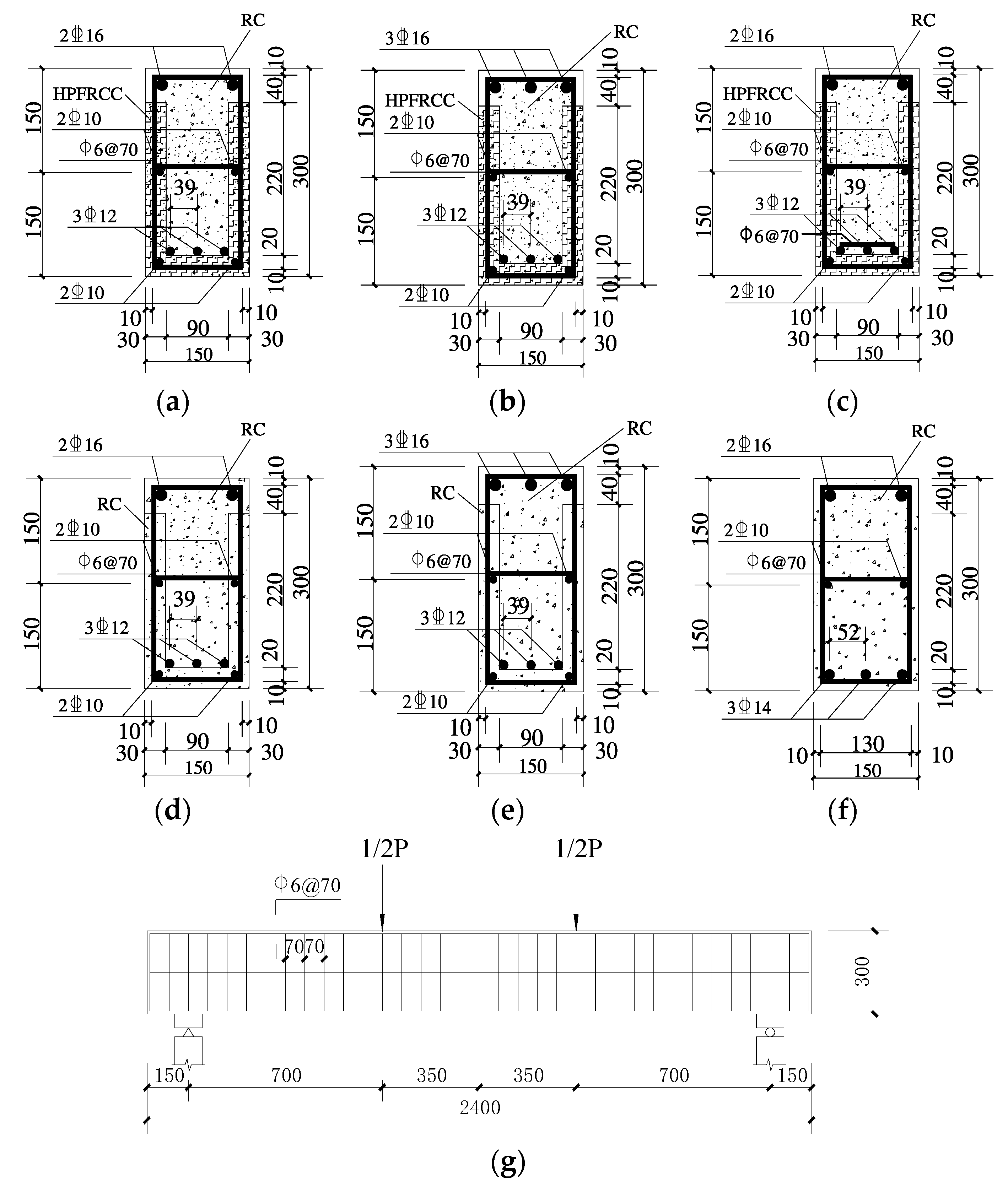
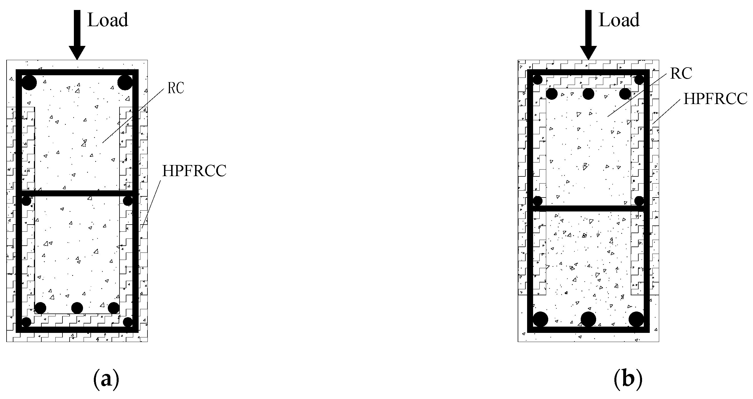
A total of six beams were designed according to the research needs. These beams consisted of three HPFRCC precast mold shell prefabricated monolithic composite beams, two precast concrete mold shell prefabricated monolithic composite beams, and one monolithic cast-in-place formed beam. The objective was to analyze the influence of the precast mold shell material and the use of cast-in-place construction on the flexural performance of the frame beams. The length of the laminated beams was 2.4 m, with a calculated length of 2.1 m and a shear-to-span ratio of 2.5. The cross-sectional dimensions of the beams were 150 mm × 300 mm, and the thickness of the prefabricated mold shells was 30 mm. The reinforcement mesh connections were welded. The detailed parameters of each specimen are presented in Table 1, while the cross-sectional dimensions and reinforcement configuration of the test beam can be found in Figure 1. Since the beam upper in the frame structure will be subjected to a negative bending moment in an earthquake, “negative bending moment” means that the upper part of the beam is in tension and the lower part is in compression; a reverse loading control experiment group was set up in this test, as shown in Figure 2.

Table 1.
Main parameters of specimens.
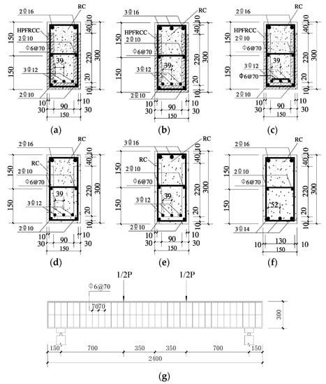
Figure 1.
Section size and reinforcement form of the test beam: (a) specimen E-1 profile; (b) specimen E-2 profile; (c) specimen EW-3 profile; (d) specimen R-4 profile; (e) specimen R-5 profile; (f) specimen Z-6 profile; (g) beam longitudinal section. (The symbol “ ” refers to the grade of HPB300 reinforcement in the Chinese standard, and the symbol “
 ” refers to the grade of HRB400 reinforcement.).
” refers to the grade of HPB300 reinforcement in the Chinese standard, and the symbol “” refers to the grade of HRB400 reinforcement.).

Figure 2.
Loading direction: (a) forward loading; (b) reverse loading.
The process of casting the specimen is divided into two steps: (i) welding the reinforcement mesh and casting it as one piece with the U-shaped HPFRCC mold shell/plain concrete mold shell, as illustrated in Figure 3; (ii) placing the post-reinforcement inside the HPFRCC mold shell and subsequently casting the plain concrete.
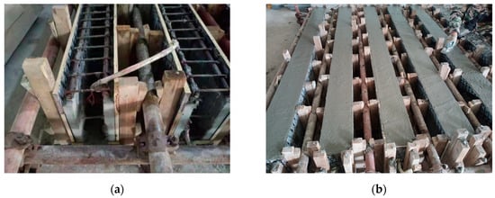
Figure 3.
The casting of HPFRCC/RC specimens: (a) the casting of prefabricated formworks; (b) post-cast concrete.
2.2. Mechanical Properties of Materials
The test specimens require two materials: HPFRCC and common concrete with a strength grade of C40. Common concrete was supplied by a commercial concrete supplier, while the HPFRCC material was prepared with cement, fly ash, quartz sand, and fiber, among other components; the mix proportion is shown in Table 2. The fiber volume admixture was set at 2%, and the fiber used was KURALINK–II–12 mm, imported from Japan. The basic performance parameters of the fiber can be found in Table 3.
Table 2.
Mix proportion of HPFRCC.
Table 3.
Basic performance index of PVA fiber.
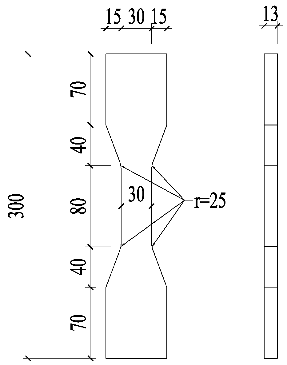
During the casting process, in addition to the main test specimens, three additional cubic test blocks with dimensions of 100 mm × 100 mm × 100 mm, three prismatic test blocks with dimensions of 100 mm × 100 mm × 300 mm, and three dumbbell-type test blocks were simultaneously prepared. The mechanical properties of these specimens were evaluated following the specifications outlined in the “Standard Test Method for Mechanical Properties of Highly Ductile Fiber Reinforced Cementitious Composites” [17]. Axial tensile tests were performed on dumbbell-shaped specimens with the dimensions depicted in Figure 4 to obtain the axial tensile strength and tensile stress–strain curves. The resulting tensile stress–strain curves are presented in Figure 5. The mechanical property parameters of HPFRCC materials and ordinary concrete can be found in Table 4.

Figure 4.
Dimensions of dumbbell-type tension specimens (unit: mm).
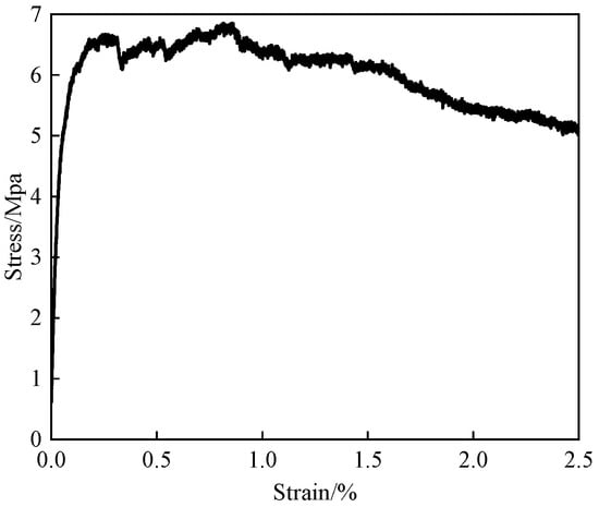
Figure 5.
Tensile stress–strain curve of HPFRCC.
Table 4.
Mechanical properties of HPFRCC and concrete.
The longitudinal reinforcement, lumbar reinforcement, and erection reinforcement were all constructed using HRB400 grade reinforcement, and the grade of the hoop reinforcement was HPB300.
2.3. Test Loading Scheme and Measurement Point Arrangement
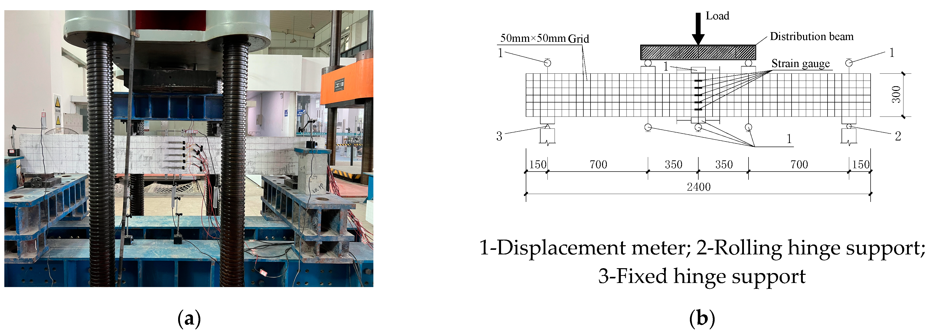
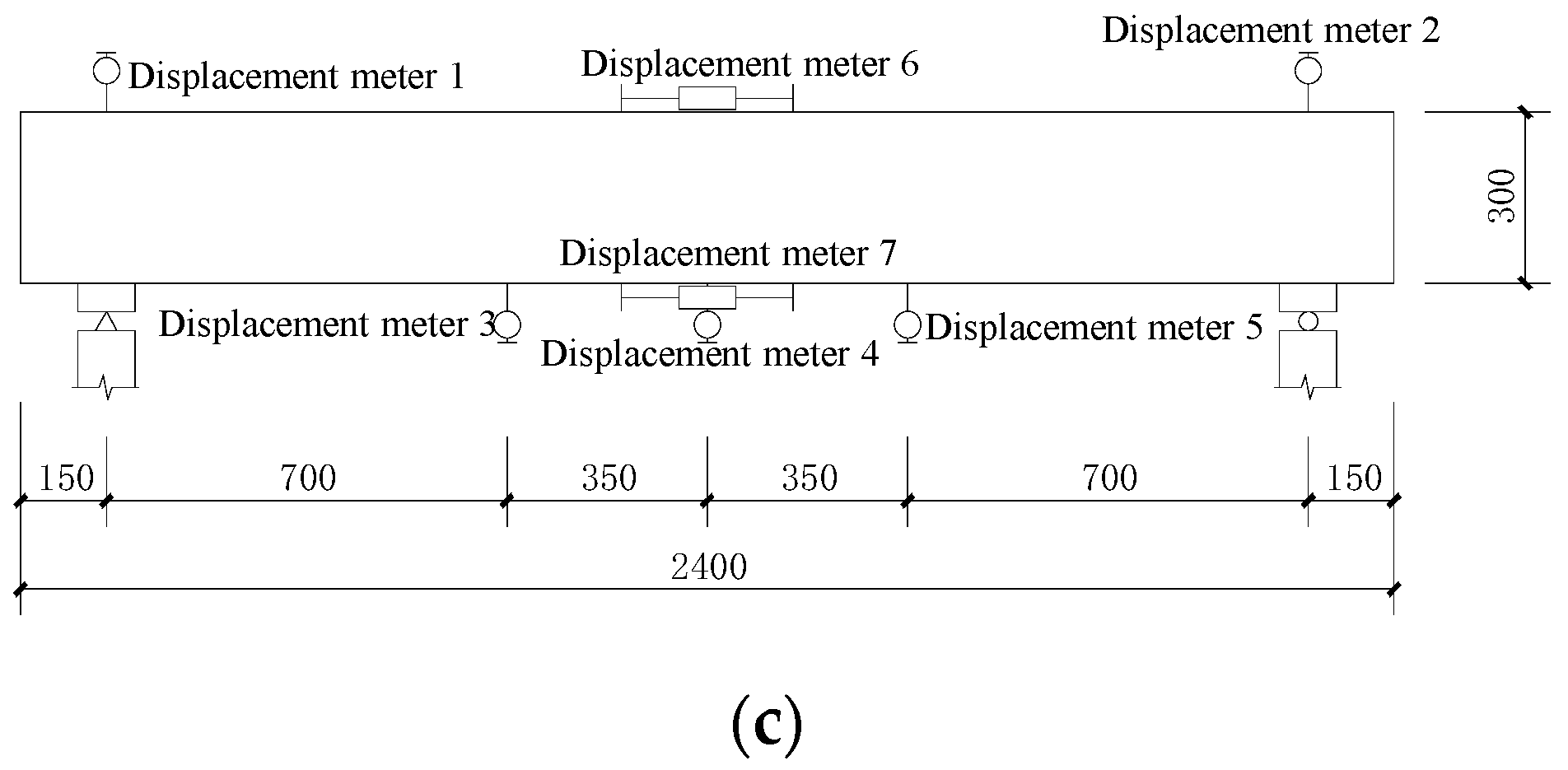
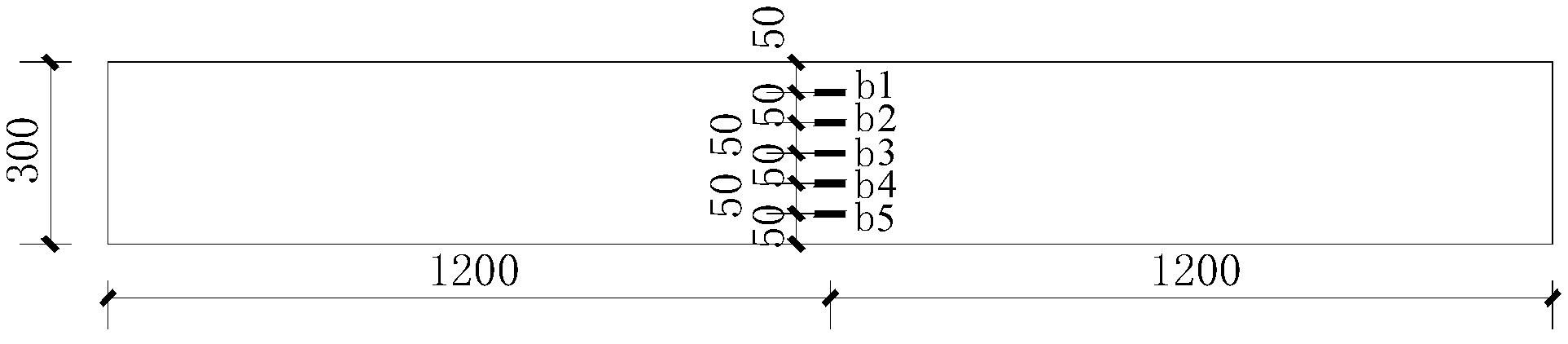
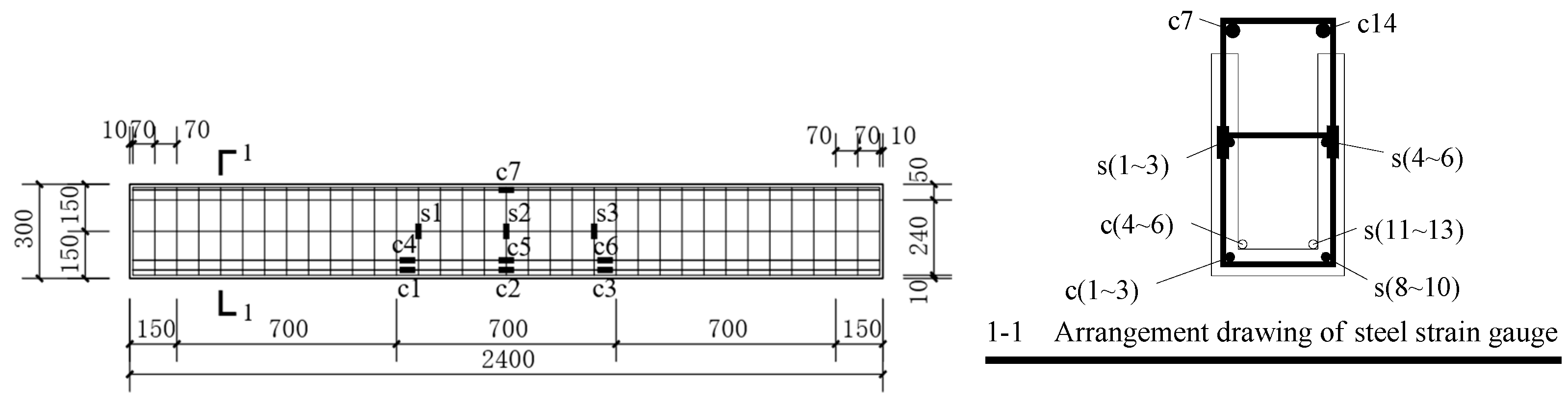
Figure 6 illustrates the bending performance test device and the layout of measurement points for the beam in this experiment. The loading equipment employed was a YAW-5000 pressure testing machine (Changchun New Testing Machine Co., Ltd, China). Two concentrated force points are utilized for loading, creating a pure bending section within the span. The pressure is applied by the jack and the reaction beam, the vertical load is transferred to the beam through the distribution beam, and the load value is measured by the pressure transducer. The experimental loading initially starts with load control at a rate of 0.2 kN/s. Each load increment is 2 kN, and the load is held for 300 s until reaching 30 kN. Then, the loading method switches to displacement control at a rate of 0.5 mm/min. Each displacement increment is 2 mm, and the load is held for 600 s. Once the displacement reaches 30 mm, the displacement increment is changed to 5 mm and the load is held for 600 s. The loading process continues until the displacement reaches 60 mm, at which point the loading is stopped. Seven displacement gauges were utilized to measure the displacements within the beam’s span, including the displacements at the two loading points, supports, and the transverse displacements of the upper and lower sections, as depicted in Figure 6c. Additionally, five concrete strain gauges were positioned on the side of the purely bending section within the span of the beam, as shown in Figure 7. Furthermore, three steel strain gauges were affixed to each tensile longitudinal reinforcement in the purely bending section, and three steel strain gauges were attached to the hoop reinforcement, as illustrated in Figure 8. Throughout the loading process, close attention was paid to crack development, and changes in crack width were recorded using a 150 ×crack observer.


Figure 6.
Layout of test equipment and measuring points: (a) field test device layout; (b) schematic diagram of the test setup and measurement point arrangement (unit: mm); (c) displacement meter number.
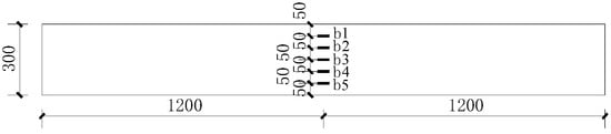
Figure 7.
Arrangement of concrete strain gauges.
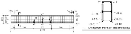
Figure 8.
Arrangement drawing of reinforcement strain.
3. Experimental Results and Analysis
3.1. Failure Mode
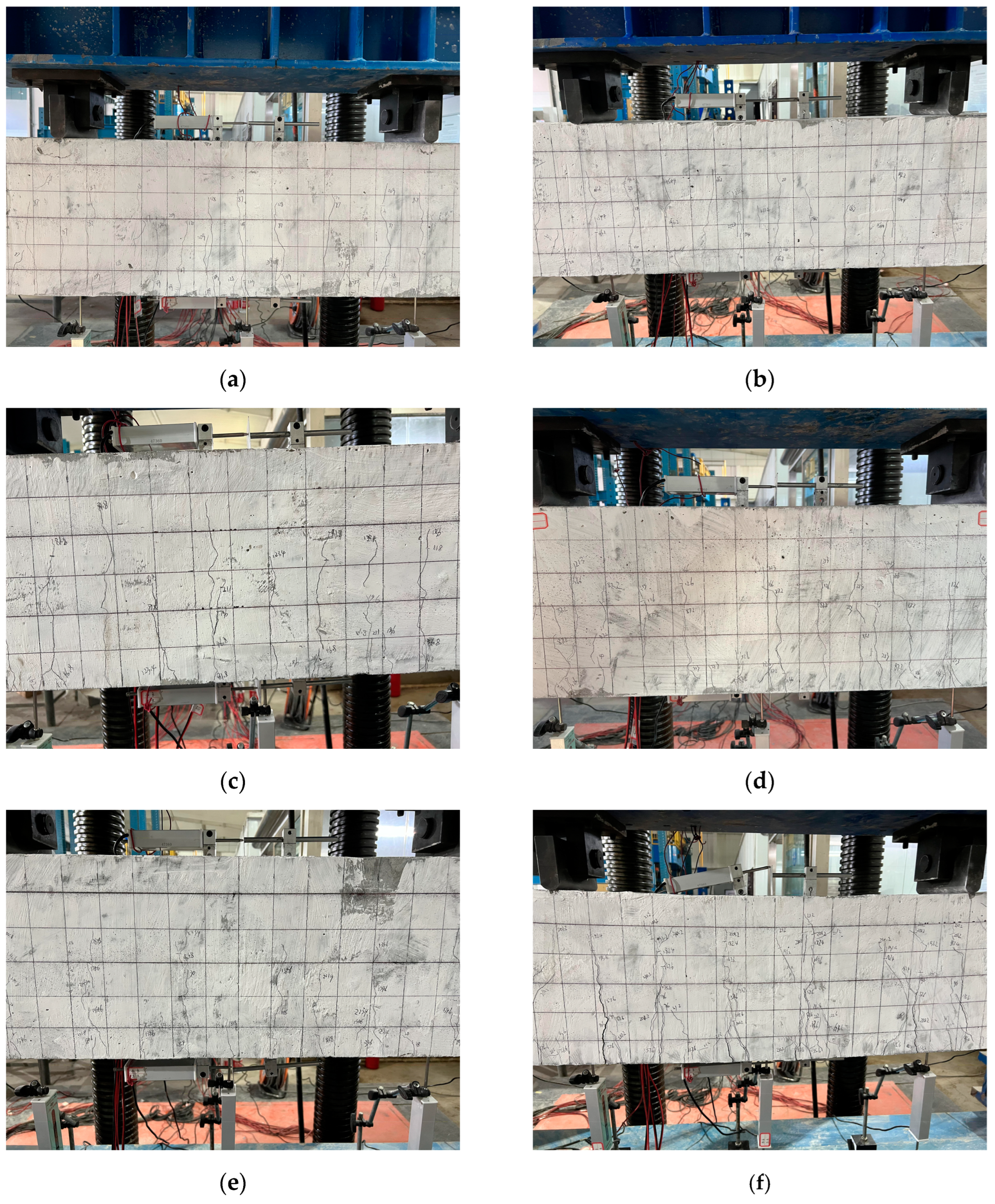
After the yielding of the tension steel reinforcement, the neutral axis of the six specimens rose, and the height of the compressed zone decreased. The compressive strain in the concrete of the compressed zone increased until it reached the ultimate compressive strain of the concrete. At that point, the concrete in the compressed zone was crushed, and all specimens exhibited good ductile behavior, resembling a flexural failure with appropriate reinforcement. The failure mode of each specimen beam at a load of about 210 kN is shown in Figure 9.

Figure 9.
The failure mode of the pure bending section of the test beam: (a) specimen E-1; (b) specimen E-2; (c) specimen EW-3; (d) specimen R-4; (e) specimen R-5; (f) specimen Z-6.
In the case of the HPFRCC (high-performance fiber-reinforced cementitious composite) precast shell composite beams, multiple cracks were observed. Before reaching the peak load, no debonding or slip cracks were found at the interface between the HPFRCC template and the concrete surfaces at the top and ends of the beam. This indicated the excellent overall integrity of the HPFRCC/RC (reinforced concrete) composite beams.
When peak load was reached, the compressed zone of the HPFRCC/RC composite beams showed no significant cracks, and some beams even remained undamaged. Vertical cracks at the mid-span propagated from the flexural zone toward the compressed zone. As the loading continued, since the HPFRCC mold shell contained fiber material, it could continue to bear the load with the reinforcement after the beam was cracked, which could limit the crack development to some extent.
After reaching the peak load, as the loading continued, a distinct “sizzling” sound could be heard as the cracks in the beam progressively opened. At that point, the width of vertical cracks at the mid-span gradually increased. Horizontal cracks started to appear at the loading point in the compressed zone, and as the loading continued, these horizontal cracks propagated toward the mid-span. When the concrete in the compressed zone was crushed and the beam underwent failure, the HPFRCC/RC composite beams exhibited fewer diagonal cracks in the shear span region compared to ordinary concrete beams. Furthermore, the width of these cracks was smaller. This indicated that HPFRCC could effectively enhance the shear capacity of the beam.
3.1.1. Influences of Different Precast Shell Materials on Failure Mode
When beam E-1 was loaded to 17.6 kN, the first vertical microcrack with a length of 9.42 mm appeared in the tensile zone at a position about 150 mm below the loading point on the left side in the frontal mid-span of the beam, and one vertical microcrack appeared. With the increase in load, the number of new microcracks on top of the original microcracks gradually increased. At the location where the crack occurs, the tensile force is jointly borne by the fibers and reinforcement after the HPFRCC cracked. When the loading reached 170 kN, the concrete at the right loading point of the front side of the beam started to crack, and 18 vertical micro-cracks appeared in the mid-span of the back side of the beam, of which the longest micro crack was 208.93 mm; when the loading reached 209 kN, the first crack with obvious width appeared in the tensile area of the mid-span of the back side of the beam, and the width of the crack was 0.1 mm and the length was 195.63 mm. A total of 26 cracks appeared in the mid-span of the back side of the beam, of which the longest crack was 219.57 mm. After the test stopped loading, the maximum width of the final crack was 4.1 mm and the longest crack was 245 mm.
When the load of beam R-4 was loaded to 28.2 kN, the first vertical crack with a length of 12.96 mm appeared in the front mid-span of the beam, and one vertical crack appeared. At the location where the crack was created, the concrete directly lost its tensile capacity, and the reinforcement was used to bear the tensile force of the crack. As the load increased, the number of new cracks was low, and the cracks gradually extended to the compression zone. When the load increased to 30 kN, the first crack appeared in the back mid-span of the beam with a length of 70.12 mm and there was one vertical crack. When the load reached 126 kN, more cracks appeared in front of the first crack with obvious width in the mid-span; the width of the crack was 0.21 mm, the length was 132.69 mm, and 10 vertical cracks appeared in the span of the back side of the beam, the longest of which was 182.86 mm. When loading to 213 kN, the maximum crack width of the pure bending section at the back of the beam was 0.51 mm, the length was 202.67 mm, and there were 15 vertical cracks in the mid-span of the back of the beam, of which the longest crack was 217.86 mm. After the test stopped loading, the maximum width of the final crack was 7.32 mm and the longest crack was 251.3 mm.
When beam Z-6 was loaded to 30 kN, the first vertical crack with a length of 28.13 mm appeared in the tension zone in the frontal mid-span of the beam near the left side about 75 mm below the loading point, and one vertical crack appeared. At the location where the crack was produced, the concrete directly lost its tensile capacity and the reinforcement was left to bear the tensile force of the crack. With the increase in load, the crack width gradually became larger and the crack gradually extended to the pressure zone. When the load was increased to 167.6 kN, the first crack with obvious width appeared in the back mid-span of the beam; the width of the crack was 0.32 mm and the length was 206.25 mm, and there were 12 cracks in the back mid-span of the beam, of which the longest crack was 206.25 mm. When the load was increased to 182.4 kN, the maximum width of the crack in the pure bending section of the back of the beam was 0.69 mm and the length was 224.0 mm, and a total of 12 cracks appeared in the mid-span of the back side of the beam, of which the longest crack was 234.0 mm. When loading to 210.2 kN, the maximum crack width of the pure bending section at the back of the beam was 1.76 mm and the length was 234.52 mm, and there were 14 cracks in the back span of the beam, of which the longest crack was 253.77 mm. After the test stopped loading, the maximum crack width was 5.35 mm and the longest crack was 272.5 mm.
In summary, and combined with Figure 9a,d,f, it can be analyzed that under the same load, the cracks of beam E-1 show “cracks are micro cracks with smaller width and more cracks” than those of beam R-4 and beam Z-6. When cracks occur in the tensile zone of the HPFRCC/RC assembled monolithic laminated beam, due to the high tensile strain capacity and excellent crack control ability of the fibers in HPFRCC material, the HPFRCC material can work together with the reinforcement, which can improve the damage resistance of the member.
3.1.2. Failure Modes of Reversed-Loaded Composite Beams
From Figure 9b,e it can be observed that beam E-2 exhibited a higher number of cracks compared to beam R-5 under the same reverse force. The cracks in beam E-2 were characterized as “fine and dense”. On the other hand, beam R-5, with a concrete mold shell, had fewer cracks, but they extended further into the compressive zone compared to beam E-2. The crack extension length into the compressive zone was longer in beam R-5 than in beam E-2. However, the crack widths in beam R-5 were wider than those in beam E-2 with an HPFRCC mold shell. The widest crack width in beam E-2 was 5 mm, while the crack width in beam R-5 was 6.38 mm. In beam E-2, there were almost no transverse cracks in the compressive zone. Conversely, beam R-5 exhibited more severe crushing of the compressed concrete, along with more transverse cracks and spalling of concrete. This enhanced ductility in the compressed zone could be attributed to the presence of the HPFRCC mold shell.
3.1.3. Failure Modes of Forced Longitudinal Reinforcement with Mesh Transverse Reinforcement Composite Beams
Due to a construction error, beam EW-3 was refabricated. Since beam EW-3 was not fabricated from the same batch as the other test beams, there were differences in mechanical properties of the material and other specimens. Therefore, specimen beam EW-3 may not be comparable to the other specimen beams in terms of various properties. The experimental data were only used as data accumulation for the reference of subsequent studies.
From Figure 9a,c it can be observed that the laminated beam EW-3, which was treated with post-cast longitudinal reinforcement in the form of reinforcement mesh, exhibited a significantly higher number of cracks compared to beam E-1. However, the width of most cracks in beam EW-3 was narrower than that of beam E-1, with a difference of only 2.86 mm. There were no main cracks with significantly greater widths. Additionally, the length of vertical cracks extending into the compression zone in beam EW-3 was 255.72 mm, whereas in beam E-1, it was 247 mm. The vertical crack length extending into the compression zone was also shorter in beam EW-3. The use of reinforcement mesh as the post-cast longitudinal reinforcement improved the ductility of the beam and inhibited the development and extension of cracks.
3.2. Load–Deflection Curve Analysis at Midspan
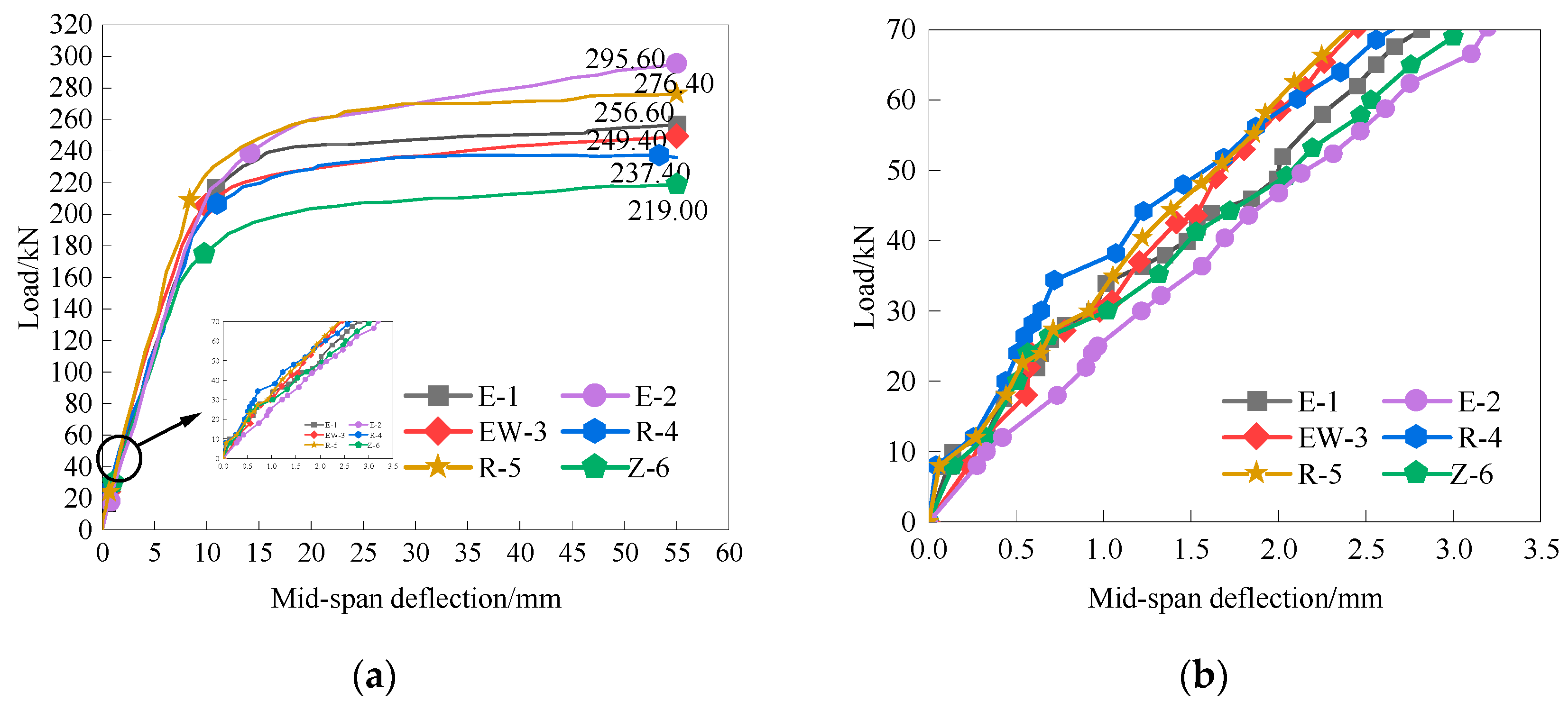
The load–span deflection curves of the six specimens are shown in Figure 10.
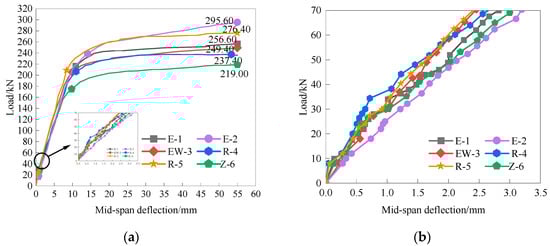
Figure 10.
Specimen beam load–mid-span deflection curve: (a) curve of load–mid-span deflection; (b) enlarged view before the working stage with cracks.
Table 5 displays the measured cracking load, yield load, peak load, and deflection values of the six test beams.
Table 5.
Test beam characteristic point load and characteristic point deflection.
3.2.1. Influences of Different Precast Shell Materials
The influence of the mold shell material on the performance of laminated beams was investigated by comparing test beams with different mold shell materials. Two types of mold shell materials were used in this study: high-performance fiber-reinforced cementitious composite (HPFRCC) and ordinary concrete. Additionally, the performance of the test beams was compared with that of beams cast in a monolithic form.
- Before cracking, all test beams were in the elastic stage, exhibiting a linear relationship between load and displacement. The slope of the curve for specimen R-4 was slightly larger than that of specimen E-1, indicating that the initial stiffness of the ordinary RC (reinforced concrete) precast shell composite beam was greater than that of the HPFRCC precast shell composite beam. This was primarily due to the lower elastic modulus of the HPFRCC material compared to ordinary concrete.
- Before the yielding of the longitudinal reinforcement, the load–deflection curve of specimen R-4 had a greater slope compared to that of specimen E-1, indicating that the former had a higher stiffness than the latter. Because of the presence of fibers in the HPFRCC/RC composite beam in the tensile zone after cracking, compared with the RC composite beam, the HPFRCC can bear the load after cracking, and both sides of the cracked section are still pulled together by the fibers to restrain the development of the concrete crack. This indirectly improves the stiffness of the HPFRCC/RC composite beam, resulting in the stiffness of the R-4 specimen being only slightly higher than that of the E-1 specimen. Specimen E-1 had a higher yield load than specimen R-4, by 5.59%. This was attributed to the PVA fibers present in the composite beam shell, which could bear and transmit a portion of the tensile force and work in synergy with the steel reinforcement. This cooperation could delay the yielding of the tensioned longitudinal reinforcement to some extent, thus increasing the yield load of the beam.
- After the yielding of the longitudinal bars, it was observed that the deformation of specimen E-1 was significantly smaller than that of specimen R-4 under the same level of loading. Additionally, the peak load of specimen E-1 was 8.1% higher than that of specimen R-4. However, the increase in bearing capacity of specimen E-1 was not substantial compared to that of specimen R-4. Moreover, the spanwise vertical displacement of specimen E-1 was considerably smaller than that of the RC laminated beam under the same level of loading.
- Under the same longitudinal reinforcement ratio, the HPFRCC/RC composite beam exhibits a significant increase in load-bearing capacity compared to ordinary RC beams. The addition of fibers enhances the tensile performance of the beam, thereby improving its bending resistance to some extent.
- The peak load of specimen E-1 is consistently higher than that of the monolithically cast specimen Z-6. Specifically, specimen E-1 has an increased peak load and yield load, by 17.2% and 24.55%, respectively, compared to specimen Z-6. Under the same level of load, the deformation of specimen E-1 is much smaller than that of specimen Z-6, indicating that the inclusion of HPFRCC material improved the load-bearing capacity and deformation performance of the structure.
3.2.2. Analysis of Bending Performance of Composite Beams under Reversed Loading
This study analyzed the bending performance of HPFRCC prefabricated molded-shell laminated beams under negative bending moments by examining the interchange of the compressive and tensile zones in the test beams.
- Under the same reverse loading conditions, specimen E-2 exhibits a significantly higher flexural load-carrying capacity compared to specimen R-5. Before the yielding of longitudinal reinforcement, due to the higher stiffness of concrete compared to HPFRCC, specimen R-5 has a steeper slope and larger gradient in the load–deflection curve. Under the same level of load, the deformation of specimen R-5 is smaller than that of specimen E-2. After the yielding of longitudinal reinforcement, specimen E-2 has a steeper slope and larger gradient in the load–deflection curve. This indicates that HPFRCC material improves the beam’s crack resistance and tensile performance.
- During reverse loading, the precast shell’s U-shaped notch is facing downward, and the HPFRCC shell is in the compressed zone. The yield load of specimen E-2 is 10.51% higher than that of specimen R-5, and the peak load is increased by 6.95%. HPFRCC material enhances the flexural load-bearing capacity and ductility of the beam.
3.2.3. Influence of Forced Longitudinal Reinforcement with Mesh Transverse Reinforcement on the Performance of Composite Beams
By comparing different methods of forced longitudinal reinforcement, we could analyze the impact of using reinforcement mesh and directly placing longitudinal reinforcement inside the shell on the performance of the beam.
- By placing the longitudinal reinforcement in the form of a reinforcement mesh in the mold shell and subsequently pouring the concrete, the test beams exhibited a linear elastic stage before the yielding of the longitudinal reinforcement. Moreover, the load–deflection curves of each beam showed significant overlap, indicating the minimal influence of the reinforcement form on the mechanical properties of the beams before yielding.
- Before the yield of reinforcement, the stiffness of the beams before the yielding of the longitudinal reinforcement was higher in the case of the reinforcement mesh utilized in specimen EW-3 compared to the HPFRCC/RC laminated beam E-1 treated with direct placement of longitudinal reinforcement in the mold shell.
3.3. Moment–Curvature Curve Analysis
The bending moment–section curvature curves of the six specimens were shown in Figure 11.
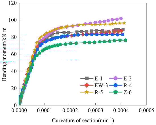
Figure 11.
Bending moment−curvature of section.
As illustrated in Figure 11, the bending of the beam induces rotation in the normal section within the pure bending region. The bending process can be divided into three distinct stages: the uncracked stage, the cracked stage, and the damaged stage. During the uncracked stage, there is a linear relationship between the bending moment and section curvature. In the cracked stage, the relationship between the bending moment and section curvature becomes curvilinear, with the section curvature and deflection experiencing accelerated growth. In the damaged stage, the relationship between the bending moment and section curvature tends to flatten out, resembling a horizontal curve.
Before the yielding of the tensile reinforcement, irrespective of the presence of a prefabricated mold shell material or other factors related to the cast-in-place method, the moment–section curvature curve was essentially similar. During the second stage of crack development, in the vicinity of cracks, most of the concrete in the tensile zone lost its load-carrying capacity, resulting in the transfer of tensile forces to the reinforcement and fiber material. Consequently, the relationship between bending moment and section curvature became curvilinear, with the section curvature and deflection increasing at an accelerated rate. In the third stage of damage, the longitudinal reinforcement reached its yield point, leading to concrete crushing in the compressed zone and section failure. In this stage, the bending moment–curvature relationship approximated a horizontal straight line. Under the same bending moment, specimen E-1 exhibits lower curvature, enhanced ductility, and superior damage resistance compared to specimens R-4 and Z-6.
3.4. Load–Reinforcement Strain Curve Analysis
The load–strain curves for each longitudinal reinforcement of the specimen beams are depicted in Figure 12. It can be observed that during the elastic phase, the differences in steel strains among the specimen beams were minimal. However, once the beams entered the working stage with cracks, the strain in the longitudinal reinforcement of the HPFRCC/RC laminated beam was lower compared to that in the other beams under the same load. This was because the PVA fibers present in the HPFRCC/RC laminated beam worked in conjunction with the longitudinal tensile reinforcement to share the tensile forces, resulting in slower growth of longitudinal reinforcement strain.
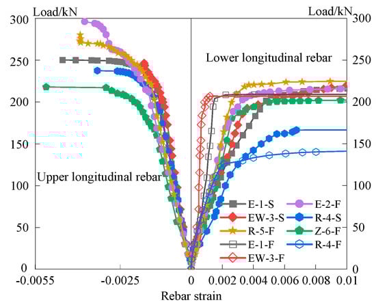
Figure 12.
Load−strain curve for longitudinal rebar of the specimen beam. (In the figure, “S” indicates the longitudinal reinforcement in the formwork, and “F” forced the longitudinal reinforcement under stress).
Moreover, the bridging tensile effect of the PVA fibers across the cracks contributed to a significantly higher yield point of the longitudinal reinforcement in HPFRCC/RC laminated beams compared to normal concrete beams. Consequently, under the same yield load, the amount of required longitudinal tensile reinforcement could be reduced due to the enhanced tensile properties offered by the HPFRCC material.
3.4.1. Analysis of the Performance of Composite Beams with Different Precast Shell Materials
From Figure 12, it can be seen that:
- During the initial loading stage of the specimens, when the applied load was relatively small and the strain in the reinforcement was low, the load–reinforcement strain curves of the composite beams with different shell materials and the monolithic beams were nearly identical.
- After the specimens cracked, the concrete transferred part of the tensile force it originally carried to the reinforcement, resulting in a sudden increase in the strain of the reinforcement. This led to a decrease in the slope of the load–reinforcement strain curve compared to the first stage.
- After cracking, in the case of the conventional RC composite beam R-4, the concrete no longer contributed to the load-bearing capacity, and all the tensile forces were transferred to the reinforcement. However, due to the higher tensile strength of HPFRCC compared to ordinary concrete, the HPFRCC/RC composite beam E-1 exhibited a larger slope and higher flexural capacity in the load–reinforcement strain curve compared to the conventional RC composite beam R-4 and the integral cast-in-place RC beam Z-6. The transition to a flatter portion of the load–strain curve occurred more gradually.
- The reinforcement yielded in beam E-1 when loaded to 94.6 kN, in beam R-4 when loaded to 63.4 kN, and in beam Z-6 when loaded to 87.2 kN. The upper reinforcement experienced significant strain only after the gradual yielding of the lower longitudinal bars. Despite having the same reinforcement arrangement, the upper longitudinal bars showed a higher slope in the load–strain curve after the yield of the lower longitudinal bars due to the presence of HPFRCC.
3.4.2. Analysis of Bending Performance of Composite Beams under Reversed Loading
From Figure 12, it can be seen that:
- During the initial loading stages of the test specimens, where the applied load was relatively small, the strain in the reinforcing bars was also small. As a result, the load–strain curves of the test beams subjected to different loading directions were nearly identical.
- However, once the test specimens cracked due to concrete cracking, a portion of the tensile force originally carried by the concrete was transferred to the reinforcing bars. This sudden increase in strain in the reinforcing bars led to a decrease in the slope of the load–strain curve compared to the first stage.
- After the occurrence of cracking in the test specimens, for composite beams with the same materials, the load–strain curve of the reinforcing bars subjected to reverse loading exhibited a larger slope, indicating a steeper curve. Before the yielding of the reinforcing bars, the load–strain curves of the HPFRCC/RC composite beam E-2 and the ordinary RC composite beam R-5 were almost identical. This suggested that the HPFRCC material did not exhibit significant performance advantages in the compressed region during the early stages.
- Reinforcement yielding occurred in beam E-2 when loaded to 133.6 kN and in beam R-5 when loaded to 140 kN. After the yielding of the reinforcement, the load–strain curve of the HPFRCC/RC composite beam E-2 showed a higher slope and stiffness compared to the ordinary RC composite beam R-5. This was because, after the occurrence of cracks, the presence of fibers in the tension zone of the HPFRCC/RC composite beam E-2 allowed the crack surfaces to remain bonded together, resulting in a lower neutral axis position and an increased height of the compressed zone compared to the ordinary RC composite beam R-5 under the same level of load. As a result, the sectional stiffness of the HPFRCC/RC beam E-2 was higher than that of the RC beam R-5.
- In the tested beams, the upper reinforcement exhibited significant strain only after the gradual yielding of the lower longitudinal reinforcement. Despite having the same reinforcement arrangement, the upper longitudinal reinforcement experienced a higher slope in the load–strain curve after the yielding of the lower reinforcement due to the presence of HPFRCC. This indicated that HPFRCC enhanced the load-carrying capacity and strain response of the upper longitudinal reinforcement after the yielding of the lower reinforcement.
3.4.3. Influence of Forced Longitudinal Reinforcement with Mesh Transverse Reinforcement on the Performance of Composite Beams
From Figure 12, it can be seen that:
- The load–rebar strain curves of the test beams with different post-cast longitudinal reinforcement treatments were almost identical due to the small load and small reinforcement strain during the pre-load period of the specimens.
- After cracking of the HPFRCC/RC composite beam specimens, the tensile forces in the bending zone in the mid-span of the test beam are shared between the fibers and the reinforcement, and internal force redistribution occurs, causing a slight increase in the reinforcement strain, resulting in a decrease in the slope of the load–strain curve compared with that of the uncracked stage.
- When the specimens cracked, the load–strain curves of the lower longitudinal bars were almost the same due to the same reinforcement of the test beams with different posterior longitudinal treatments, and the load–strain curves tended to flatten after the bars yielded.
- After cracking of the specimen, beam EW-3 showed yielding of the reinforcement when loaded to 115.6 kN. The laminated beam EW-3, with posterior longitudinal reinforcement in the form of reinforcement mesh, had a greater slope and steeper curve in the load–strain curve of the posterior longitudinal reinforcement compared to the laminated beam E-1 without any treatment.
- The upper reinforcement exhibited significant strain only after the gradual yielding of the lower longitudinal reinforcement. Due to the presence of the rear longitudinal reinforcement in the form of steel mesh, the load–rebar strain curve of the composite beam EW-3 was steeper than that of the composite beam E-1 without any treatment of the rear longitudinal reinforcement, and the failure occurred slower.
3.5. Verification of the Assumption of Plane Sections
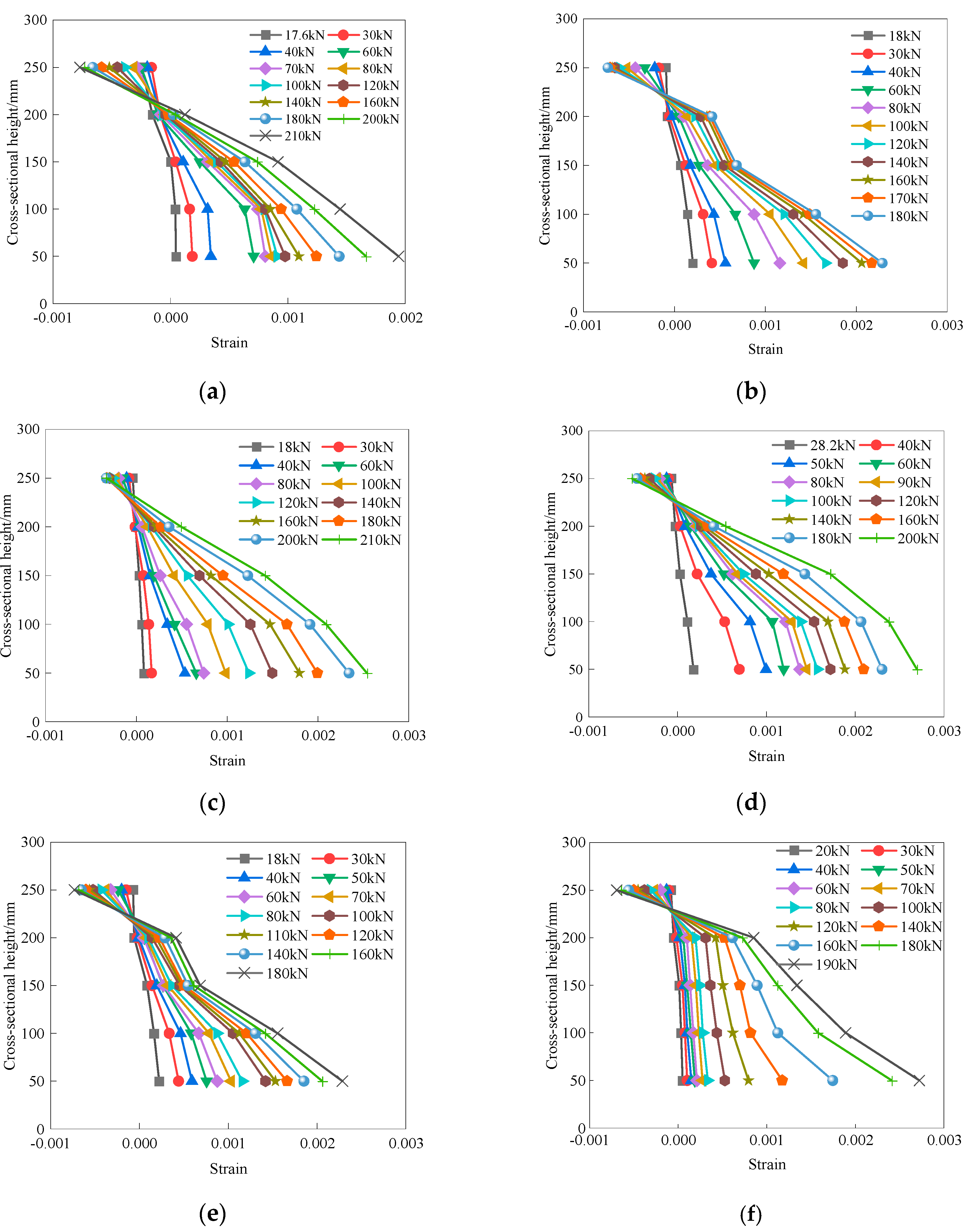
The analysis and calculation of the bending capacity of HPFRCC/RC prefabricated monolithic composite beams were based on the assumption of a plane section. Therefore, it was necessary to validate the correctness of these assumptions. Five resistance strain gauges were installed along the side face of the HPFRCC/RC prefabricated monolithic composite beam at heights of 50 mm, 100 mm, 150 mm, 200 mm, and 250 mm from the bottom of the beam (with a total height of h = 300 mm). The measured values of these strain gauges at the same moment and their variation along the height of the mid-span section are plotted in Figure 13. From Figure 13, it can be seen that the average longitudinal strain distribution along the section height of each test beam in the mid-span section under different loads is an approximately linear relationship, and the assumption of a flat section holds.
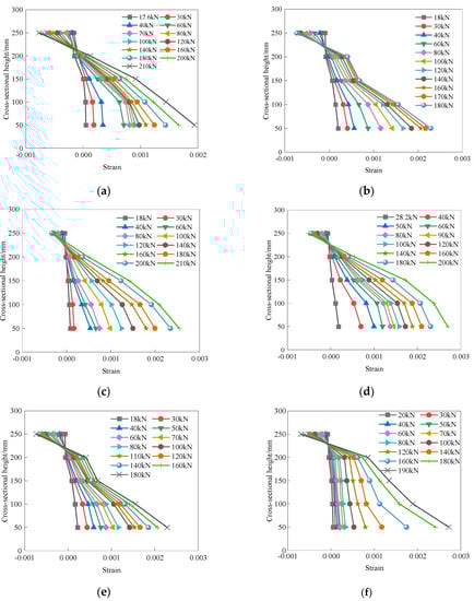
Figure 13.
Strain distribution in the specimen sections: (a) specimen E−1; (b) specimen E−2; (c) specimen EW−3; (d) specimen R−4; (e) specimen R−5; (f) specimen Z−6.
4. Conclusions
The experimental study on the flexural performance of HPFRCC prefabricated molded-shell prefabricated monolithic composite beams led to the following conclusions:
- Throughout the loading process until reaching the peak load, the HPFRCC/RC prefabricated monolithic composite beams exhibited bending failure with excellent ductility, characterized by the presence of multiple distributed cracks. Notably, no significant bond failure occurred before reaching the peak load, indicating the overall favorable bending performance and the joint behavior of the HPFRCC prefabricated monolithic composite beams.
- In comparison to conventional integral cast-in-place RC beams, the HPFRCC/RC prefabricated monolithic composite beams demonstrated a considerable increase of 17.2% and 24.55% in peak load and yield load, respectively. Moreover, when compared to standard RC prefabricated monolithic composite beams, the HPFRCC/RC prefabricated monolithic composite beams exhibited enhancements of 8.1% and 5.59% in peak load and yield load, respectively.
- In contrast to integral cast-in-place RC beams and RC prefabricated monolithic composite beams, the HPFRCC/RC prefabricated monolithic composite beams exhibited denser and narrower cracks, with slower crack propagation rates and reduced crack widths. These characteristics demonstrate the potential of HPFRCC materials to enhance the damage resistance of structural components. Furthermore, the use of HPFRCC formwork enables its application as factory prefabricated components in prefabricated structures.
- The load–strain curves of the reinforcing bars showed that the presence of PVA fibers in the HPFRCC material contributed to a reduction in strain growth, resulting in improved tensile properties and enhanced crack bridging capability. This led to a higher yield point of the reinforcement and a potential reduction in the required amount of longitudinal tensile reinforcement.
- Due to the different loading directions, the U-shaped shell bottom plate experienced compression. The increase in the reinforcement ratio in the compression and tension zones, along with the addition of fibers and the increased effective height of the cross-section under positive loading, significantly enhanced the bending capacity of the tested beams.
Author Contributions
Conceptualization, T.L. and K.G.; Investigation, K.G. and H.J.; Data curation, K.G. and H.J.; Writing—original draft preparation, K.G.; Writing—review and editing, K.G. and T.L.; Funding acquisition, T.L. All authors have read and agreed to the published version of the manuscript.
Funding
This research was funded by [Natural Science Basic Research Program of Shaanxi] grant number [No. 2021JQ-873], [Shaanxi Provincial Department of Education Youth Innovation Team Construction Research Plan Project] grant number [No. 21JP140] and [Xijing University Senior Talent Fund] grant number [No. XJ20B08].
Data Availability Statement
The data presented in this study are available on request from the corresponding author.
Acknowledgments
We would like to express our sincere gratitude to the Shaanxi Provincial Natural Science Foundation for their generous financial support. Their funding enabled us to conduct this research and make significant contributions to the field of civil engineering. We would also like to acknowledge the Shaanxi Provincial Department of Education for their support through the Youth Innovation Team Building Research Program. Their encouragement and assistance were invaluable in facilitating the success of this project. Furthermore, we are grateful to Xijing University for their support through the High-Level Talents Fund. Their investment in our research allowed us to attract top talent and advance our understanding of key issues in civil engineering. We would like to extend our appreciation to all the individuals and organizations involved in these funding programs for their continuous support and guidance throughout the research process. Without their contributions, this study would not have been possible.
Conflicts of Interest
The authors declare no conflict of interest.
References
- Yuan, F.; Hu, R. Experimental study on the flexural behavior of ECC and ECC-concrete composite beams hybrid reinforced with steel and FRP bars. Concrete 2022, 77, 66–71. (In Chinese) [Google Scholar]
- Shi, F.W.; Sun, C.H.; Liu, X.G.; Wang, H.; Zong, L. Flexural behavior of prefabricated composite beam with cast-in-situ UHPC: Experimental and numerical studies. Structures 2022, 45, 670–684. [Google Scholar] [CrossRef]
- D’ambrisi, A.; Focacci, F. Flexural Strengthening of RC Beams with Cement-Based Composites. J. Compos. Constr. 2011, 15, 707–720. [Google Scholar] [CrossRef]
- Calabrese, A.S.; D’Antino, T.; Colombi, P.; Carloni, C.; Poggi, C. Fatigue Behavior of PBO FRCM Composite Applied to Concrete Substrate. Materials 2020, 13, 2368. [Google Scholar] [CrossRef] [PubMed]
- Calabrese, A.S.; D’antino, T.; Colombi, P.; Carloni, C.; Poggi, C. Fatigue Behavior of FRCM Strengthened RC Beams: State of the Art and Future Developments. In Proceedings of the 10th International Conference on FRP Composites in Civil Engineering, Istanbul, Turkey, 8–10 December 2021; pp. 201–212. [Google Scholar] [CrossRef]
- Calabrese, A.S.; D’antino, T.; Colombi, P.; Poggi, C. Study of the Bond Behavior of FRCM-Masonry Joints Using a Modified Beam Test. In Proceedings of the XXIV AIMETA Conference, Rome, Italy, 15–19 September 2019; pp. 455–471. [Google Scholar] [CrossRef]
- Calabrese, A.S.; D’antino, T.; Colombi, P.; Poggi, C. Study of the influence of interface normal stresses on the bond behavior of FRCM composites using direct shear and modified beam tests. Constr. Build. Mater. 2020, 262, 120029. [Google Scholar] [CrossRef]
- Calabrese, A.S.; D’antino, T.; Colombi, P. Experimental and analytical investigation of PBO FRCM-concrete bond behavior using direct and indirect shear test set-ups. Compos. Struct. 2021, 267, 113672. [Google Scholar] [CrossRef]
- Li, V.C.; Wang, S.X.; Wu, C. Tensile Strain-Hardening Behavior of Polyvinyl Alcohol Engineered Cementitious Composite (PVA-ECC). Mater. J. 2001, 98, 483–492. [Google Scholar] [CrossRef]
- Sirijaroonchai, K.; El-Tawil, S.; Parra-Montesinos, G. Behavior of high performance fiber reinforced cement composites under multi-axial compressive loading. Cem. Concr. Compos. 2010, 32, 62–72. [Google Scholar] [CrossRef]
- Siva, C.R.; Pankaj, A. Flexural behavior of reinforced concrete beams with high performance fiber reinforced cementitious composites. J. Cent. South Univ. 2019, 26, 2609–2622. [Google Scholar] [CrossRef]
- Nguyen, D.L.; Thai, D.K.; Nguyen, H.T.T.; Nguyen, T.Q.; Le-Trung, K. Responses of composite beams with high-performance fiber-reinforced concrete. Constr. Build. Mater. 2021, 270, 121814. [Google Scholar] [CrossRef]
- Tang, W.H.; He, X.X. Effect of engineered cementitious composite superimposed layer on flexural behavior of beams. Build. Struct. 2022, 52, 6. (In Chinese) [Google Scholar]
- Zhang, R.; Hu, P.; Zheng, X.H.; Cai, L.H.; Guo, R.; Wei, D.B. Shear behavior of RC slender beams without stirrups by using precast U-shaped ECC permanent formwork. Constr. Build. Mater. 2020, 260, 120430. [Google Scholar] [CrossRef]
- Liang, X.W.; Wang, P.; Xu, M.X.; Yu, J.; Li, L. Flexural behavior and capacity analysis of rc beams with permanent uhpc formwork. Eng. Mech. 2019, 36, 95–107. (In Chinese) [Google Scholar]
- Hu, Z.H.; Zhou, Y.W.; Hu, B.; Huang, X.X.; Guo, M.H. Local use of ECC to simultaneously enhance the shear strength and deformability of RC beams. Constr. Build. Mater. 2022, 353, 129085. [Google Scholar] [CrossRef]
- JC/T 2461-2018; Standard Test Method for the Mechanical Properties of Ductile Fiber Reinforced Cementitious Composites. Ministry of Industry and Information Technology of the People’s Republic of China: Beijing, China, 2018. (In Chinese)


Disclaimer/Publisher’s Note: The statements, opinions and data contained in all publications are solely those of the individual author(s) and contributor(s) and not of MDPI and/or the editor(s). MDPI and/or the editor(s) disclaim responsibility for any injury to people or property resulting from any ideas, methods, instructions or products referred to in the content. |
© 2023 by the authors. Licensee MDPI, Basel, Switzerland. This article is an open access article distributed under the terms and conditions of the Creative Commons Attribution (CC BY) license (https://creativecommons.org/licenses/by/4.0/).