Article

Experimental and Numerical Investigation of a Novel Demountable Timber–Concrete Composite Floor

by
Hooman Eslami
1,
Laddu Bhagya Jayasinghe
2 and
Daniele Waldmann
3,*
1
Faculty of Science, Technology and Medicine (FSTM), University of Luxembourg, L-4365 Esch-sur-Alzette, Luxembourg
2
Department of Earth and Environmental Sciences, Ludwig-Maximilians-Universität München, Theresien Str. 41, 80333 Munich, Germany
3
Institute for Solid Structures, Technical University of Darmstadt, Karolinenplatz 5, 64289 Darmstadt, Germany
*
Author to whom correspondence should be addressed.
Buildings 2023, 13(7), 1763; https://doi.org/10.3390/buildings13071763
Submission received: 4 June 2023 / Revised: 5 July 2023 / Accepted: 6 July 2023 / Published: 11 July 2023
(This article belongs to the Section Building Materials, and Repair & Renovation)

Abstract

:
In recent years, there has been an increasing interest in timber–concrete composite (TCC) floors as a sustainable structural solution. Until now, only a few studies have investigated the demounting of TCC floors, which is essential to increase sustainability and improve the end-of-life environmental benefits of a floor system. This study investigates an innovative and straightforward demountable TCC slab that has notched and bolted connections. Six downscaled slabs are tested under four-point bending. The results show that the slab system has high composite action with an efficiency of 0.73. A three-dimensional finite element model is developed and calibrated with the experimental result. The model is used to study the influence of several parameters, such as the shape and dimensions of the notch as well as the bolt location on the load-bearing capacity and the load-deflection behavior of the slab. The results show that the failure tends to be more ductile when a birdsmouth-shaped notch is used, and the bolt is placed within the notch. Moreover, the load-bearing capacity of the shear connection increases by increasing the distance of the notch to the end of the slab and using a triangular notch.

1. Introduction

The building industry is responsible for significant energy and natural resource consumption and greenhouse gas emission. Construction and demolition wastes have a substantial share in waste generation. For example, in Europe, this goes up to more than one-third of all waste production [1]. To develop new structural solutions, it is critical to consider two key factors. The first factor is the promotion of the use of more sustainable construction materials, while the second factor is the incorporation of design for deconstruction (DfD) [2] principles into the development of structural elements. DfD encourages the design of structural elements with reflection on their end-of-life scenario in addition to their load-bearing capacity and durability [3]. DfD elements can be demounted, reused, or recycled with limited energy, time, and resource consumption. Regarding sustainable construction materials, in the last few years, the focus on timber and engineered wood products as the appropriate solutions has increased, as they are renewable, have a low carbon footprint, and have high carbon storage capacity. However, when considering timber structural elements, such as slabs and beams, some unfavorable features, such as springiness, vibration, and poor sound insulation, have to be considered, mostly in the serviceability stage. These drawbacks can be improved by using timber as hybrid solutions such as timber–concrete composite (TCC) [4,5].
TCC structural systems have been extensively studied and employed as different structural elements in both new construction and rehabilitation applications since the early decades of the last century [6,7]. TCC slabs are typically designed with the concrete slab on the top predominantly subjected to compression, while all or most of the timber section at the bottom bears tensile stresses. If the system is effectively developed, it can exhibit a three to five times higher load-bearing capacity compared to conventional timber or concrete systems [8]. In addition, a proper shear connector system is used to effectively transfer the shear between the timber and the concrete components. The shear connection between the two materials is a critical component in the performance of TCC slabs [9]. It directly impacts the composite behavior, stress distribution, deformations, and the design of the slab. In the last two decades, new shear connections were developed using different methods, such as nails [10], screws [11], adhesives [12], perforated plates [13], and notches [14], to connect concrete and timber. Figure 1 illustrates some of these connection techniques. These studies investigated the mechanical properties of shear connections like stiffness and strength through push-out and bending tests. Among all, notched shear connections offer an exceptional combination of mechanical performance and simplicity since they are easy to construct and present high stiffness and strength [6]. Moreover, notched connections are suitable for DfD as no permanent bond is needed for their fabrication. However, the failure mode in the notched connection is brittle [15,16]; therefore, it is usually accompanied by steel fasteners that are embedded in the concrete to improve the post-failure performance [17,18].
Most of the existing shear connections permanently bond timber to concrete. Consequently, the slabs in which they are used cannot easily be prefabricated, demounted, overhauled, or reused. Thus, the sustainability of these slabs is diminished. Several researchers attempted to address the prefabrication in TCC floors by proposing wet–dry [20,21,22,23] and dry–dry systems [24,25,26,27,28,29,30]. In the wet–dry system, the concrete is cast directly on the timber component, while the shear connection is implemented on the timber part. In the dry–dry system, the concrete part is precast, and the shear connection is embedded within the concrete. Subsequently, it is fastened to the timber component using screws and bolts. Although certain dry–dry systems may have the potential for disassembly, the demounting of these connections was not studied. While many researchers have investigated demountable shear connectors for steel–concrete composite floors [31,32,33,34], only a few studies investigated the deconstruction of TCC slabs. Khorsandnia et al. [35,36] developed and tested six different types of demountable connections using screws, bolts, and steel sections. The researchers addressed that the accuracy required for fabrication and assembly and the labor required for fabrication and installation are among the most crucial characteristics of deconstruction. Derikvand and Fink [37,38] introduced a demountable TCC shear connection using a self-tapping screw. The shear and bending tests showed that the connection was almost as good as a similar non-demountable one. However, the screw connection inherently showed a low stiffness and strength compared to other types of connections.
In this paper, a novel modular prefabricated TCC floor system is proposed, which is fully demountable. The novelty of this floor system corresponds to its demountable shear connection that upgrades the sustainability of the floor system since it facilitates its reusing and recycling. Also, this modular system is designed to be prefabricated in the wet–dry system so that the concrete is cast on the timber part, which is a fast process that is not labor-intensive, and overcomes the construction and assembly challenges that exist in similar floor systems. The TCC module can then be transferred to the building site and put in place in a dry–dry process. The shear connection is designed to have high stiffness and strength to achieve a high level of shear connection. This paper presents an experimental study on a downscaled model of the floor where the structural performance and fabrication process are investigated. Later, analytical and numerical studies on the floor system are presented, and a parametrical study is performed on the shear connection.

2. Experimental Study

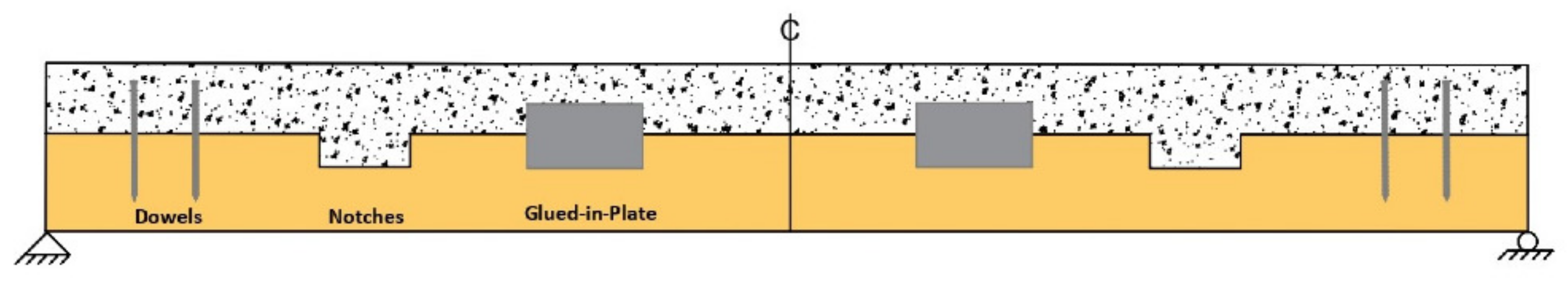
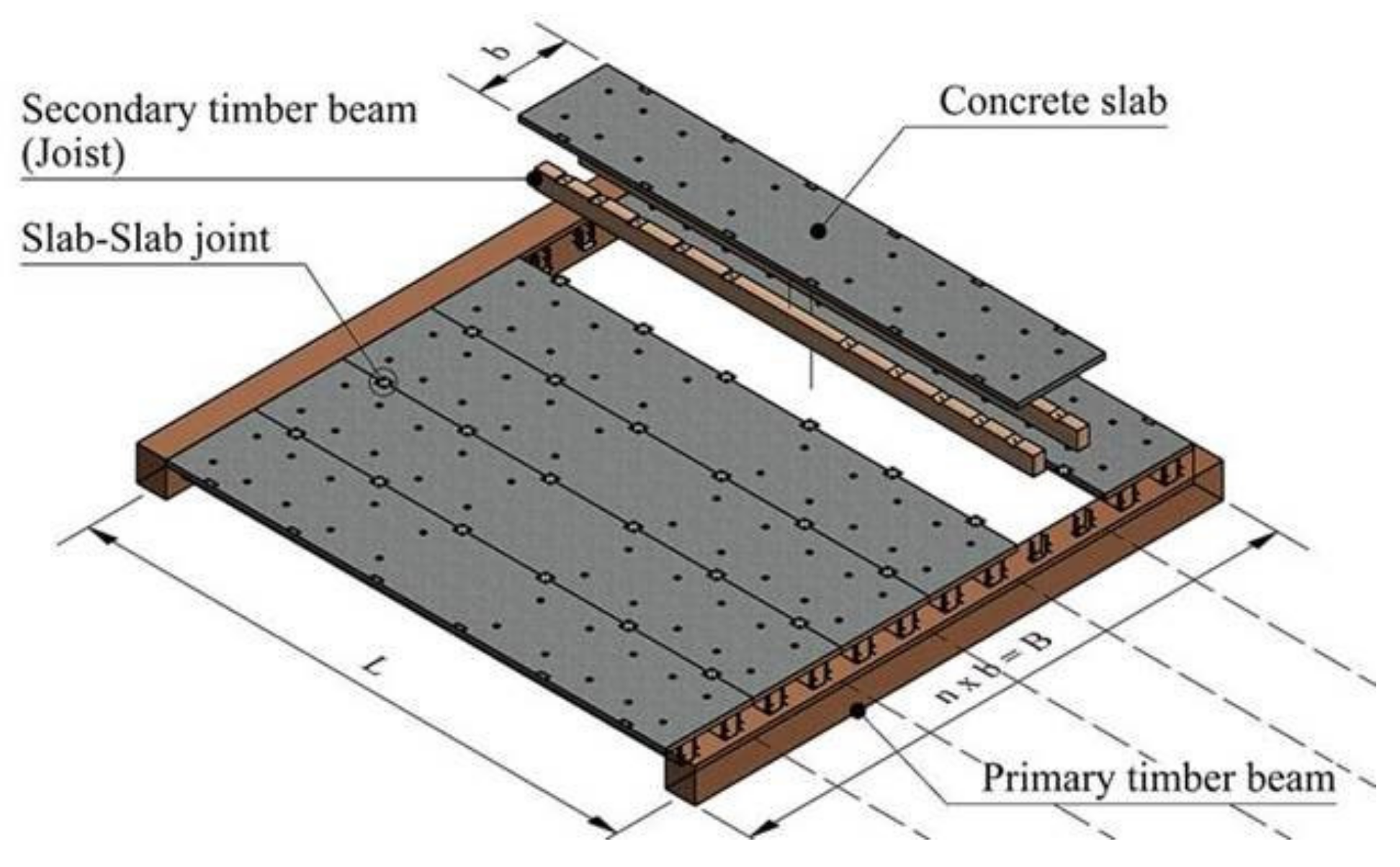
2.1. The Demountable TCC Floor System

The TCC floor system consists of a concrete layer on a timber layer that is connected via a demountable shear connection. The timber part can be in the form of joists or a timber slab, which is made from a suitable type of timber or engineered wood products as presented in Figure 2. The shear connection includes a triangular notch that transfers the shear force between the two layers. The notched connection is chosen as the shear connection because notches transfer the shear force through the direct contact of the two materials without a permanent bond. Notched connections show relatively high strength and stiffness compared to other non-binding connections [39]. The shear connection is associated with a vertical bolt instead of the commonly embedded steel fasteners in notched connections, which keeps the two layers together and avoids the uplift of the concrete. The bolt is placed in a slotted hole so that it does not resist any shear but only the uplift forces caused by the eccentric forces at the connection. The bolt is designed to perform in the elastic zone so that it does not undertake permanent deformation in favor of deconstruction and reuse.

2.2. Fabrication

Before casting the concrete, the notches and the holes for the bolt in the timber are cut, and the formworks for the bolts in the concrete are placed. The wet–dry system is used for the fabrication of the floor modules, which means that the concrete layer is directly cast against the timber part. Therefore, there is no need to consider assembly tolerances between the concrete and timber. When the concrete is hardened, the bolt formwork is removed, the bolt is installed, and the TCC module is completed. Then, the modules are transferred to the construction site and installed on the main frame of the structure as depicted in Figure 2. The TCC modules are connected to the primary beams with a simple supported connection. The dimensions of the grids of the building dictate the length (L), width (b), and number (n) of the modules. This paper investigates the fabrication and demounting possibility and the flexural behavior of one module.

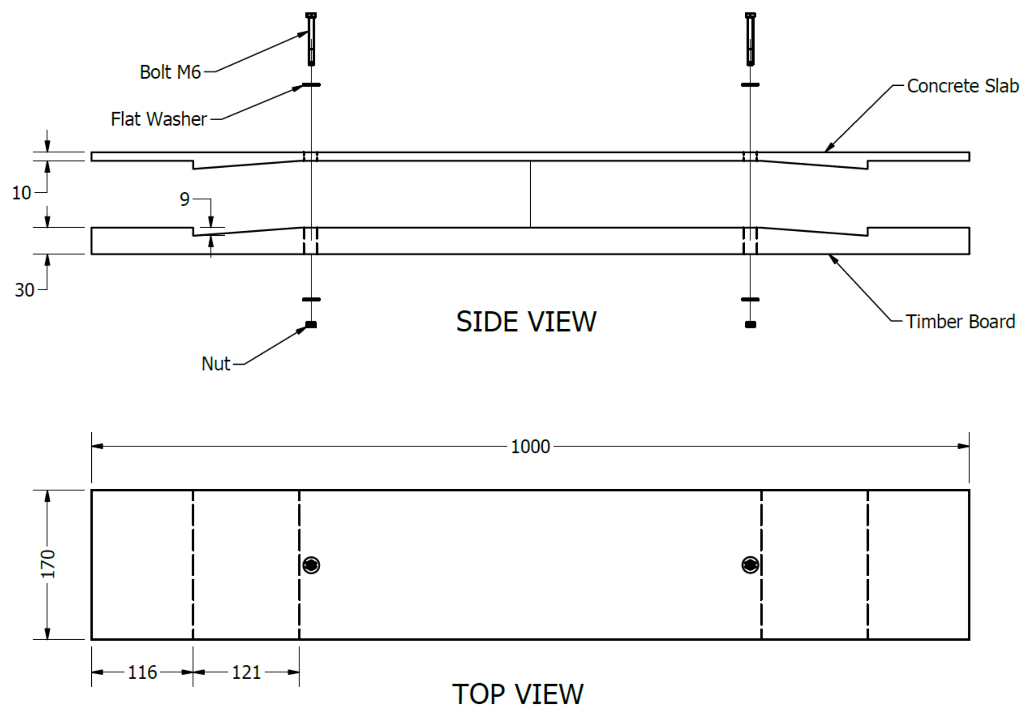
2.3. Downscaled Model
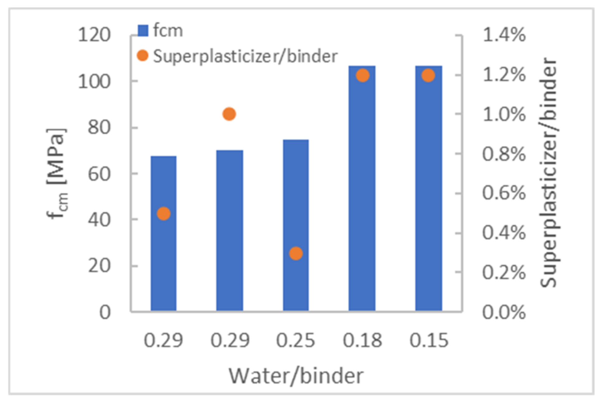
To investigate the proposed floor with the available resources and facilities, a downscaled model of the TCC slab was designed, which is presented in Figure 3. One shear connection is placed on each side of the slab. Based on the design, the concrete mixture was developed, and the timber was cut and prepared for fabrication.

2.3.1. Concrete

The concrete layer in the downscaled model of the slab has a thickness of only 10 mm, which is not deep enough for concrete with conventional aggregate sizes. Accordingly, the placement of steel reinforcement in the concrete layer is impossible; therefore, the tensile stresses due to shrinkage and loading must be borne by the concrete itself. Moreover, the concrete must fill the notched geometry without air voids. Hence, a special self-compacting mixture with fine aggregates and high tensile strength was developed. A mixture of water, high-performance binder [40], CEN standard sand [41], and superplasticizer [42] was used to develop the special mixture for the concrete layer of the downscaled element. To find the best mixture with appropriate self-compacting properties while avoiding segregation effects, five different mixtures with water–binder ratios from 0.15 to 0.29 and superplasticizer–binder ratios from 0.3% to 2.0% were batched and tested under compression according to the DIN EN 196-1 [41]. In addition, the vertical section of the samples was visually checked for segregation.
The compression strengths of the mixtures are compared in Figure 4 in the function of the water–binder ratio and the superplasticizer–binder ratio. As expected, the strength of the mixtures improved by reducing the water–binder ratio. On the other hand, the superplasticizer dosage must be adjusted separately for each water–binder ratio to achieve self-compacting properties without segregation effects. The mixture with the water–binder ratio of 0.15 was chosen based on the self-compacting behavior, lack of aggregate segregation, and compression strength. Details of the chosen mixture are shown in Table 1.
Table 2 presents the mechanical properties of the concrete used for producing the TCC slab on 28-day-old specimens. The properties include the E-Modulus under compression, strength under compression, and tensile splitting strength of the concrete. It is important to consider that, due to the thin thickness of the concrete similar to thin-walled sections, the mechanical properties may differ from standard test results [43].

2.3.2. Timber

The timber board was from the C24 strength class. The strength and stiffness of the timber material are depicted in Table 3 according to EN 338:2009 [44].

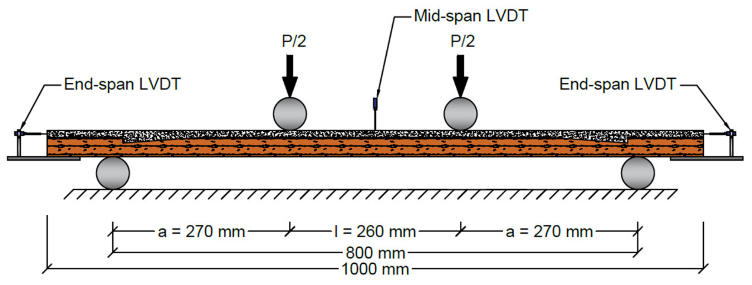
2.4. Experimental Setup

The experiment program was carried out at the Laboratory of Solid Structures at the University of Luxembourg. Six downscaled slabs were tested under a four-point bending experiment. All specimens were simply supported at a distance of 100 mm from the end of the slab and spanned a distance of 800 mm. The timber grain orientation for all specimens was aligned parallel to the span length. The loading was applied at a rate of 0.1 kN/s until the failure of the specimens. The experimental setup is shown in Figure 5. Linear Variable Displacement Transducers (LVDT) were used to measure the mid-span deflection and the slip between the concrete and timber (Figure 6). The absolute deflection of the slab w was calculated by the average of the two LVDT sensors at mid-span.

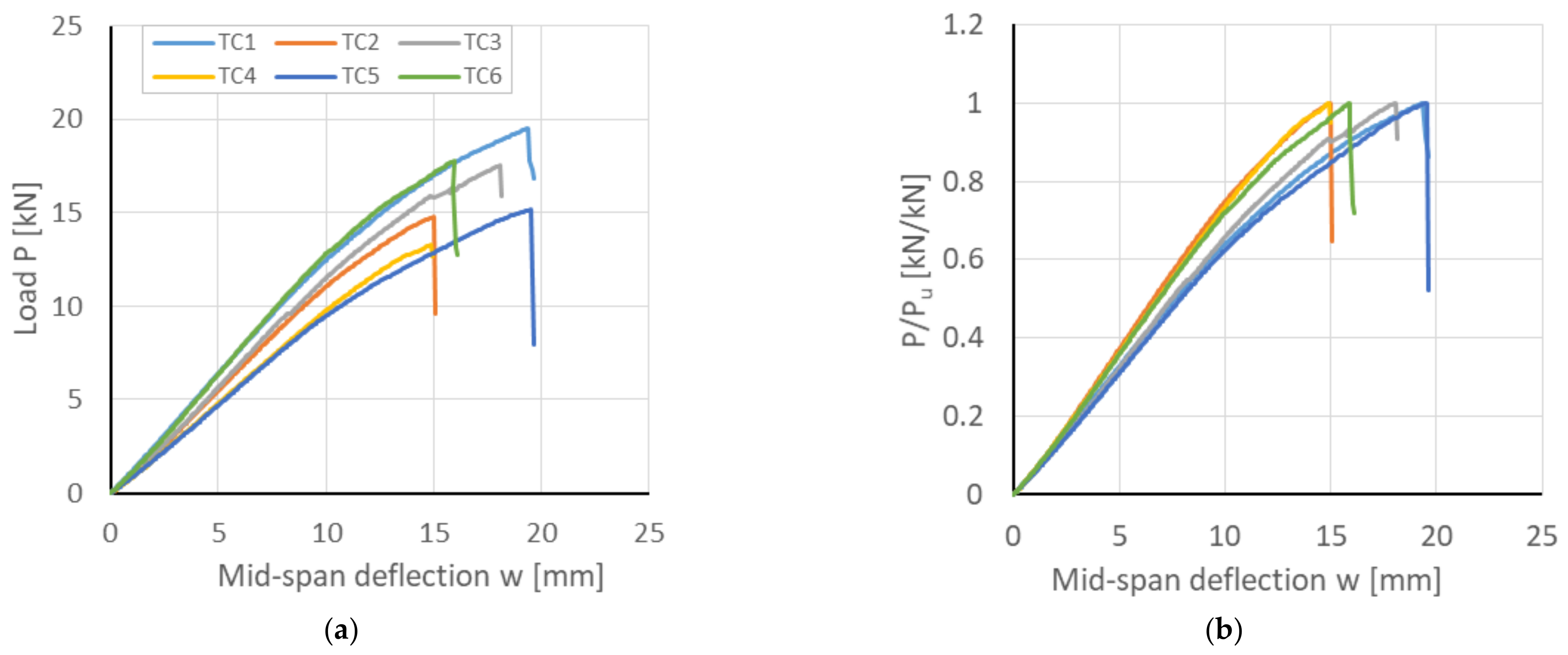
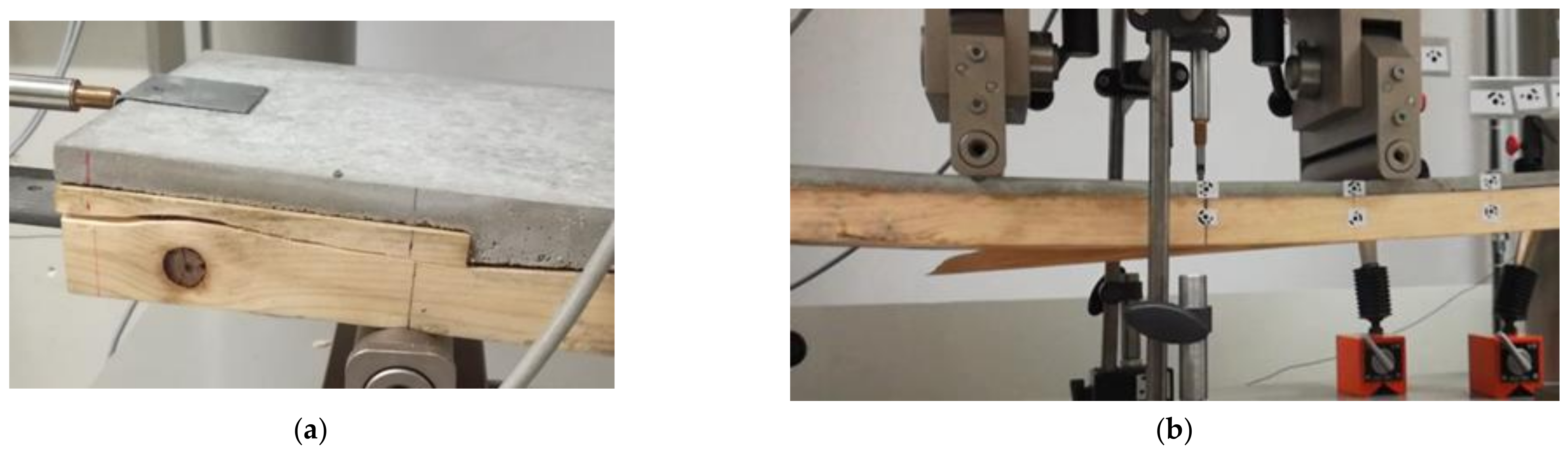
2.5. Experimental Results

Figure 7a illustrates the results of mid-span deflection versus loading for the TCC specimens. The ultimate load of the specimens primarily varies due to variations in timber properties. To address this, Figure 7b presents the normalized load-deflection graphs. The load-deflection behavior is quasi-linear at the beginning of the loading for all the specimens, and later, the slab starts to deflect nonlinearly before a brittle failure occurs. The two failure modes observed in the specimens are the shear failure in timber, which occurred from notch to end-span (Figure 8a), and the bending failure, which occurred around mid-span (Figure 8b). After the failure, the timber and concrete are still easily detachable. No permanent deformation was observed in the bolt.
The load-deflection measurements from the test results are used to calculate the bending stiffness and the effective flexural rigidity of the composite slab in different loading stages. In Table 4, the mid-span deflection and the bending stiffness at ultimate load Pu are presented as wu and ku, respectively. Accordingly, the deflection and the bending stiffness for the linear deformation part are calculated at 30% of the ultimate load P0.3 and presented as w0.3 and k0.3, respectively. The effective flexural rigidity is calculated at P0.3 with the following formula [45]:
( E I ) e f f = P 0.3 a ( 3 L 2 4 a 2 ) / 48 w 0.3
which corresponds to a four-point bending loading setup. The ultimate load and the bending stiffness vary among the specimens, which is expected due to the inherent variation in the wood properties.

2.6. Analytical Analysis
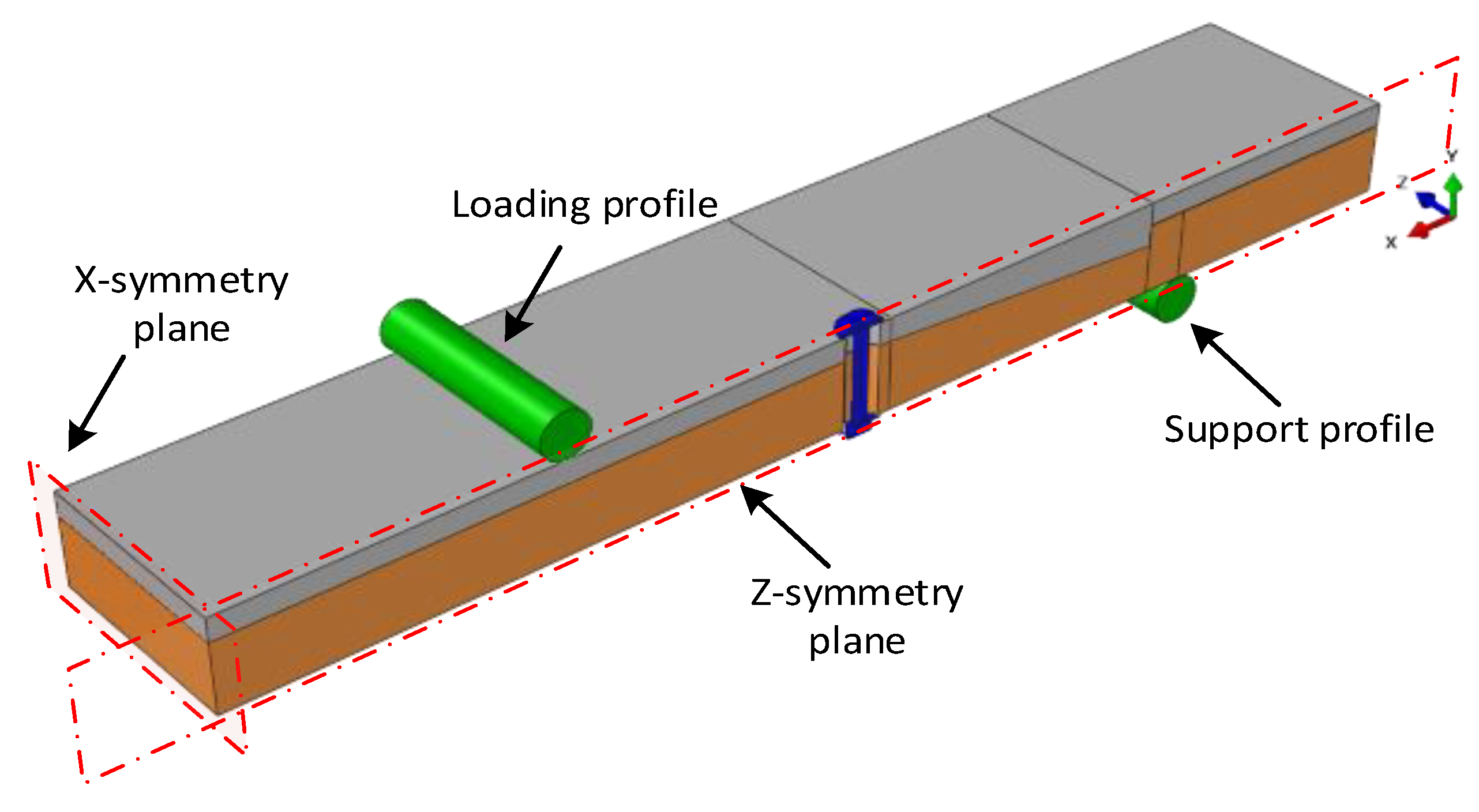
The method that is commonly used to design TCC slabs is a linear–elastic method proposed by Ceccotti [46] based on the method known as the γ-method in annex B of Eurocode 5 [47]. This method assumes that the slab is simply supported where the two individual parts, here concrete and timber, are connected through shear connections with a slip modulus of K. In this method, effective flexural rigidity is defined as:
( E I ) e f f = E c I c + γ c E c A c a c 2 + E t I t + γ t E t A t a t 2
and
γ c = 1 1 + π 2 E c A c s K l 2 ,
γ t = 1
where the subscripts c and t refer to the concrete and timber, and E, I, A, and a indicate Young’s modulus, the second moment of area, the area, and the distance from the centroid of the element to the neutral axis of the composite section, respectively. In the formula of γc, s is the space between the shear connectors, and l is the beam span. γc can vary between zero, which means no composite connection, and one, which means a full composite connection between the two layers. The slip modulus of the shear connections K and the space between them s is decisive in determining the value of γc. Based on the above formulas and the experimental results, the effective flexural rigidity of the current slab for the extension of no composite to full composite is shown in Table 5. For analytical analysis, only the linear part of the experimental results at 30% of the ultimate load is considered.
Considering the results, the efficiency of the composite slab can be calculated with the method proposed by Gutkowski et al. [48]:
E F F = Δ N Δ I Δ N Δ C
where Δ N , Δ I , and Δ C represent the theoretical deflection of no composite system, the measured deflection, and the theoretical deflection of the completely composite system, respectively. According to the experimental results and the analytical calculations, the load-deflection graphs for these three cases are depicted in Figure 9. By substituting the values of Δ N , Δ I , and Δ C in Equation (5) (where at P/Pu = 0.15, these values are 4.67, 2.20, and 1.27, respectively, as depicted in Figure 9), the efficiency of the current slab can be calculated as 0.73.

3. Numerical Study

In this section, a numerical model is presented for the investigation of the structural performance of the slabs under quasi-static loading conditions during a four-point bending test. A three-dimensional finite element (FE) model was developed using the Abaqus software package. The developed FE model was validated using the experimental results, which were described in the previous section.
The geometry of the slab has two symmetric planes. For the benefit of saving computation costs, only one-quarter of the geometry was modeled, and symmetric boundary conditions were assigned at the symmetry planes. A linear hexahedral element type with reduced integration (C3D8R) was used. The loading and support parts were modeled as a 3D analytic rigid shell. All dimensions were identical to the experimental ones. The loading was applied by displacement of the rigid loading profile in the Y-direction at a constant rate. The support was applied by constraining all the degrees of freedom of the support profile. The geometry of the model is shown in Figure 10.
The interaction between the parts was characterized by pressure–overclosure “Hard” contact in the normal and static coefficient of friction in the tangential directions. The static coefficient of friction was defined as 0.57 between timber–concrete [49] and concrete–steel [50], 0.4 between timber–steel [51], and 0.15 for all other contact pairs.

3.1. Material Modeling
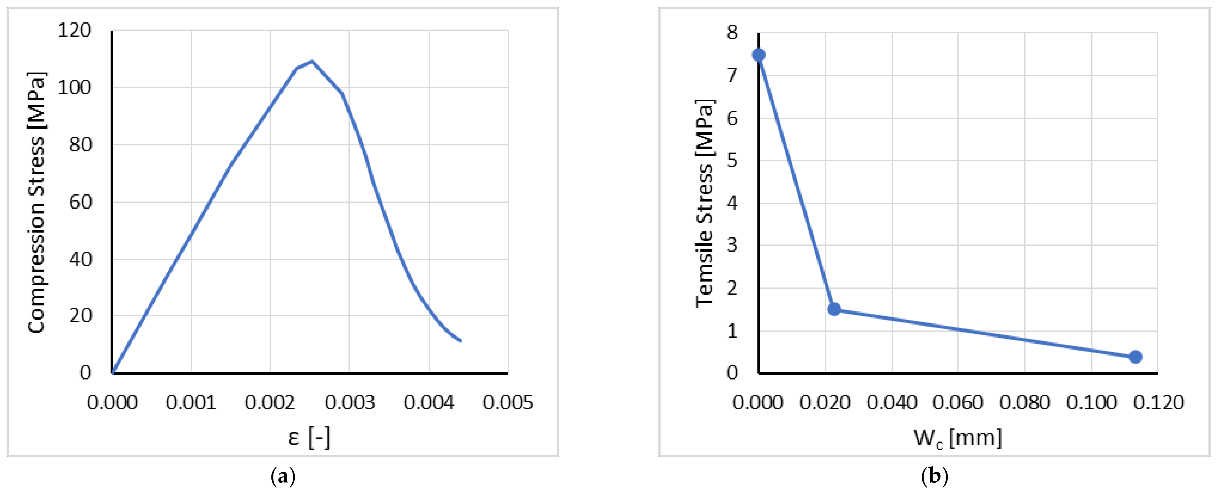
3.1.1. Concrete

The Concrete Damage Plasticity (CDP) model was used for modeling the concrete. The CDP model assumes that the main two failure mechanisms are tensile cracking and compressive crushing of the concrete material [52]. In the CDP model, the total strain tensor is defined as ε = ε e l + ε p l , where ε e l and ε p l are the elastic and plastic parts of the strain, respectively. The stress–strain relations in both compression and tension are governed by scalar damaged elasticity as [52]:
σ = ( 1 d ) D 0 e l : ( ε ε p l )
where d is the scalar stiffness degradation variable that can be in a range of 0 for undamaged material to 1 for fully damaged material, D 0 e l is the undamaged elastic stiffness of the material, ε is the total strain, and ε p l is the plastic part of the strain. The evolution of the degradation variable is defined by d = d ( σ ¯ , ε p l ) , where σ ¯ is the effective stress that is defined as [52]:
σ ¯ = def D 0 e l : ( ε ε p l )
and ε p l is the hardening variable. The damaged states in tension and compression are individually considered by two hardening variables, ε t p l and ε c p l , which refer to equivalent plastic strain in tension and compression, respectively. Accordingly, the Cauchy stress can be represented as:
σ = ( 1 d ) σ ¯
In this model, the states of failure or damage are determined with the yield function as F ( σ ¯ , ε p l ) . The yield function represents a surface in the effective stress space, which is controlled by the hardening variables. Conveniently, uniaxial loading conditions in compression and tension are considered for formulating the evolution of the hardening variables, and later, it is extended to multiaxial conditions. The uniaxial behavior is considered differently under tension and compression. Under uniaxial tension, the stress–strain behavior is considered a linear elastic response until the failure stress σ t 0 . After the failure, a softening stress–strain response represents the formation of micro-cracks. Under uniaxial compression, the response is linear until the value of the initial yield, σ c 0 , followed by a stress hardening until the ultimate stress, σ c u . Beyond that, the response is characterized by stress softening. In both tension and compression stresses, in the softening response region, the unloading response of the concrete specimen is weakened by the degrading (damage) variables d t and d c , standing for tensile and compressive damage, respectively [52].
To define the stress–strain behavior of the concrete for numerical calculations, the behavior should be extracted either from test results or from mathematical constitutive models. The concrete in this study was high-strength concrete. The stress–strain response of high-strength concrete in compression is different from conventional concrete. With an increase in the strength of concrete, the initial trend of the stress–strain response tends to become mostly linear, and the linear portion of the ascending part of the graph extends [53]. Moreover, to some extent, the strain at maximum strength becomes greater, and the descending part of the stress–strain response becomes steeper [54]. Considering the behavior of high-strength concrete and the test results, the response curve was based on the model from Carreira and Chu [55], which is as follows:
σ = f c m β ( ε   ε u ) β 1 + ( ε   ε u ) β  
and
  β = 1 1 f c m ε u E i t
where f c m is the concrete maximum stress, ε u is the strain at maximum stress, and E i t is the initial tangent modulus of elasticity. Considering the above formulas and the results from the tests on the concrete mixture presented in Section 2, the stress–strain response in Figure 11a was used as input for the CDP model.
The post-failure behavior of concrete in tension, i.e., the strain-softening for cracked concrete, can be defined by tension stiffening in the CDP model, which can be defined either by the stress–strain relation or by applying a fracture energy cracking criterion. When no reinforcement exists in the region, the latter method is preferable to avoid mesh sensitivity in the results [52]. Therefore, in this model, the post-failure behavior under tension was defined by a bilinear stress-crack opening (Wc) response as demonstrated in Figure 11b, which was calculated based on the fracture energy of concrete [56].

3.1.2. Timber

Timber is an orthotropic material that shows different mechanical behavior in three mutually perpendicular axes and has different strengths under compression, tension, and shear. Therefore, three mutually perpendicular planes needed to be defined for the timber-board part so that the mechanical properties of longitudinal, radial, and tangential axes were assigned in the right orientations. Directions 1, 2, and 3 were assigned to the X, Y, and Z axes, respectively, where direction 1 was parallel to the grain, and directions 2 and 3 were in the tangential and radial directions, respectively.
There is no predefined material model in Abaqus to model the orthotropic nonlinear behavior of timber. The material model used in this model was developed by Eslami et al. [57], which is a nonlinear anisotropic elastoplastic three-dimensional material model with failure analysis capacity that was implemented as a UMAT subroutine for Abaqus. The model associates Hoffman’s [58] yield criterion with isotropic hardening to model the plastic strain hardening behavior of timber under compression. Also, four failure criteria are defined to trigger the damage propagation under both compression and tension. Hoffman’s criterion, which is an extension of Hill’s [59] criterion, is considered for this material model because it distinguishes between the compression and tension strengths. Some timber mechanical properties, such as elasticity, strength and hardening parameters, and fracture energies, that are needed as the inputs of the material model vary for different timber types. The timber material properties that were used in the material model are shown in Table 6. These properties were calibrated based on the test results reported on the same batch of timber by Eslami et al. [57]. For further detail about the material model, its implementation, and validation and also the tests on timber material, please see reference [57].

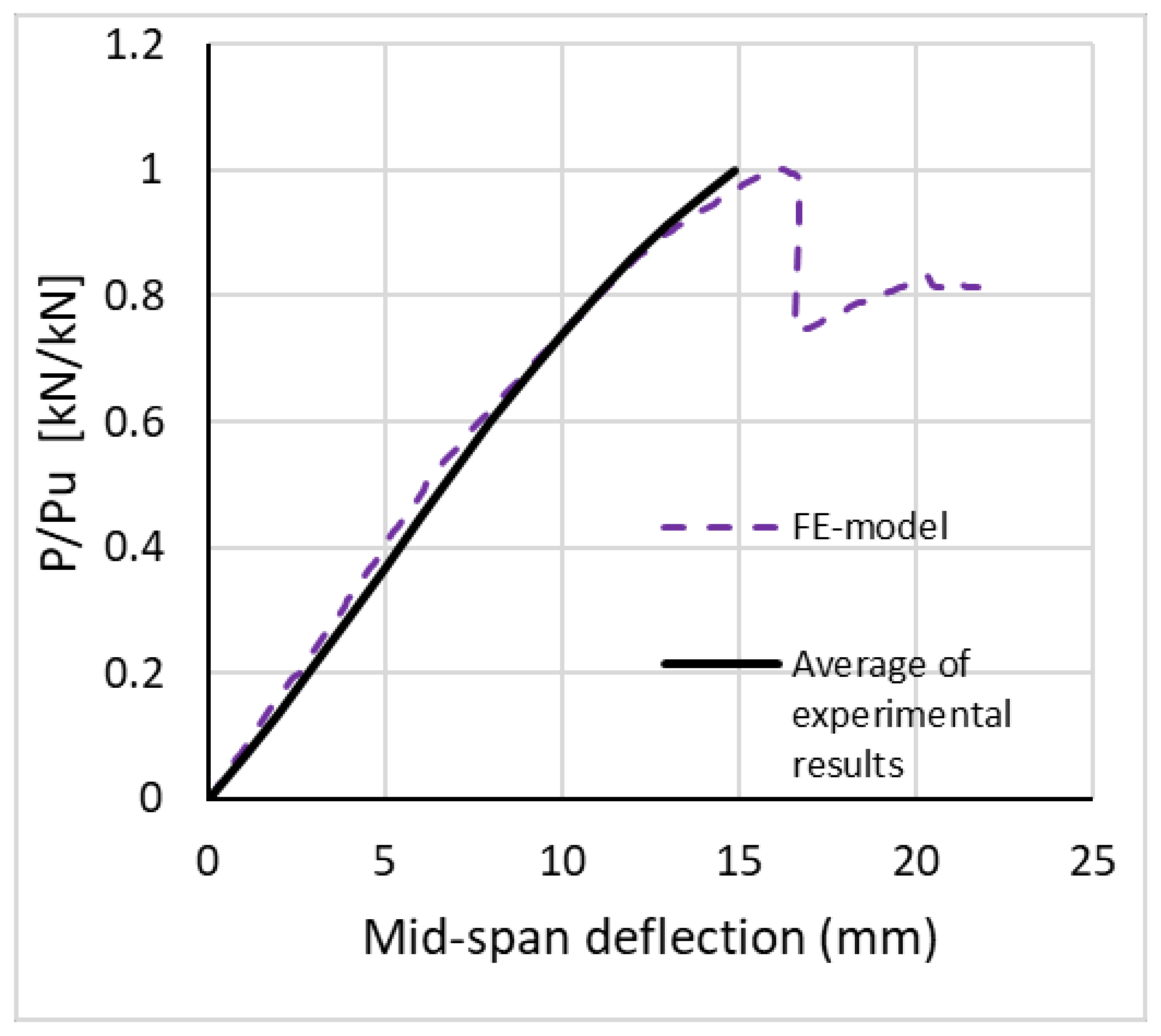
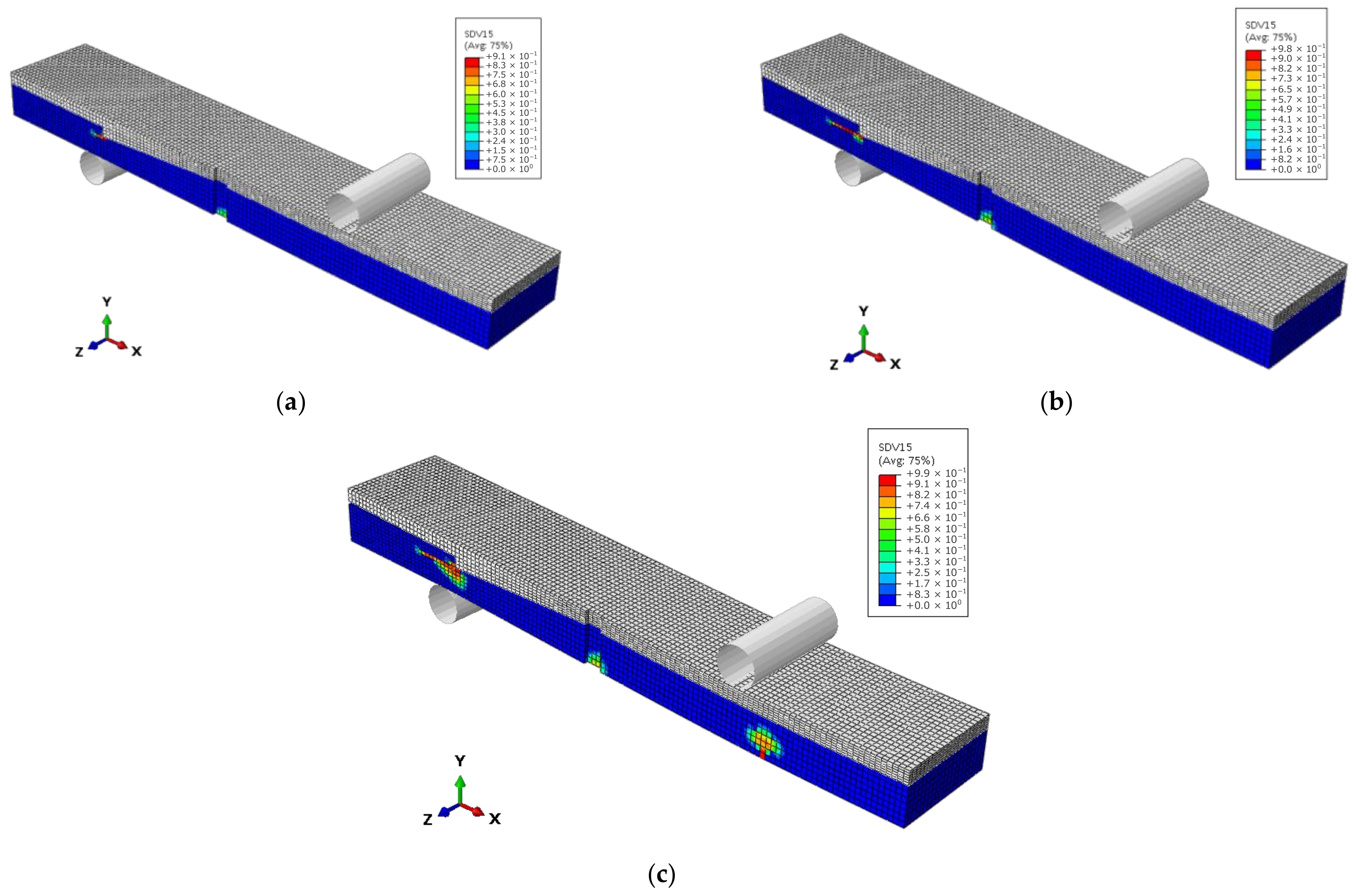
3.2. Results and Discussion
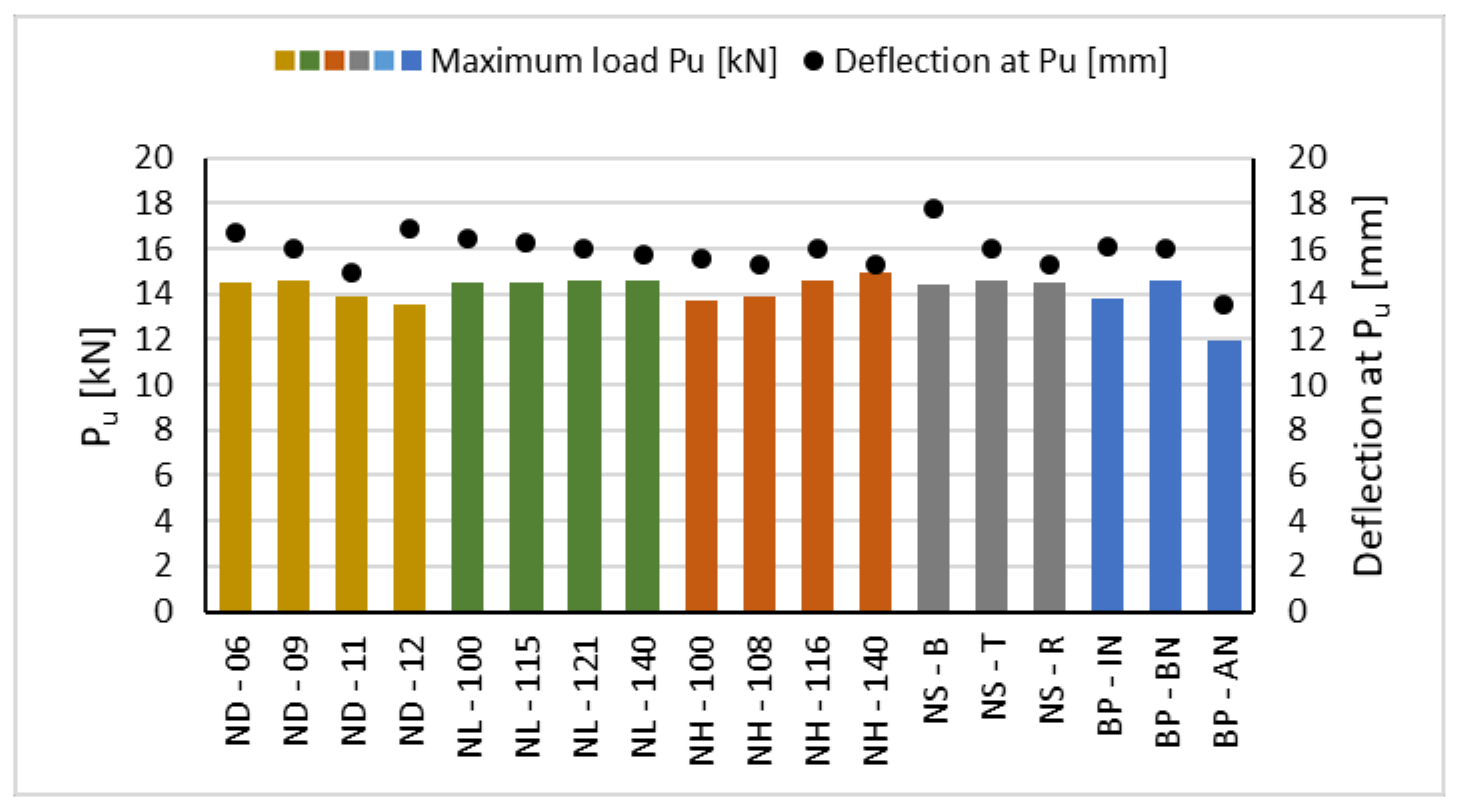
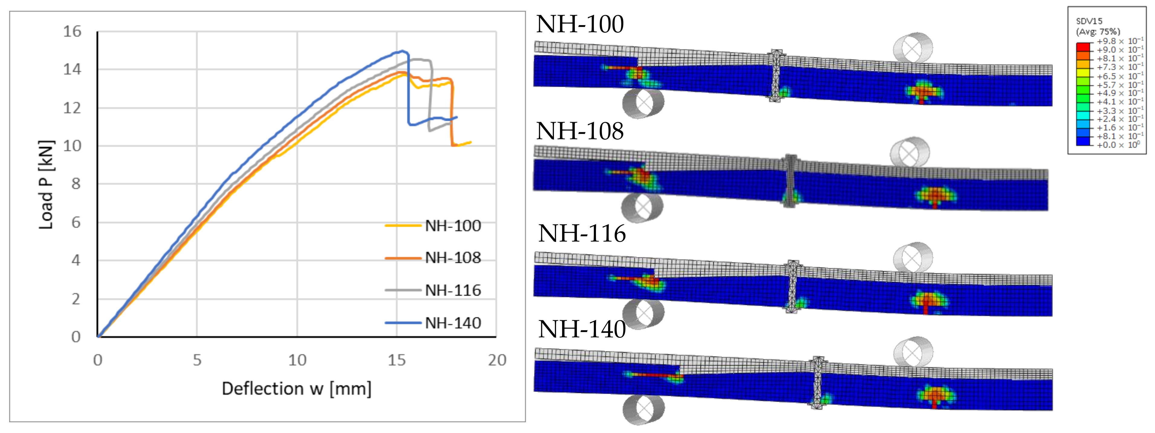
The load-deflection curve obtained from the FE model is illustrated in Figure 12 and compared with an average graph of the load displacement of the experimental results. The stiffness of the FE model is in line with the experimental results. Overall, a reasonably good correlation between the numerical and experimental results is observed. Also, the brittle failure is simulated with the numerical model.
Figure 13 illustrates the maximum principal stress distribution in the concrete and timber parts. The maximum compression stress happened at mid-span in the concrete part close to the loading zone. For the tensile stress, the concentration was in the timber part at mid-span as well as at the notched corner, which is in correlation with the damage evolution in the timber presented in Figure 14. The figure shows the damage evolution with the increase in the load. It can be observed that the first damage occurred in the vicinity of the notch. The damaged zone increased with the increase in load and propagated toward the end of the slab in the longitudinal direction. The failure occurred later when the damage was initiated and distributed between the loading part and the mid-span. The predicted failure of the model is in good agreement with the observed rupture in the timber part during the experiment, as shown in Figure 8.

4. Parametric Study

The FE model is used to perform a parametric study on the TCC slab. The models and their varying parameters are presented in Table 7. For each parameter, the primary model is compared to two or three other models. The parameters that are considered are notch depth (ND), notch length (NL), and timber length in front of the notch (NH) in addition to the shape of the notch (NS) and the bolt’s position (BP). The parameters are depicted in Figure 15. For the shape of the notch, triangular, rectangular, and birdsmouth shapes are considered. The bolt location, which in the original design is between the notch and mid-span (BN), is studied as well when located in the notch (IN) and between the notch and the end span (AN).
The ultimate load and the deflection at the ultimate load for each model are presented in Figure 16. The highest and lowest ultimate load belong to models NH-140 and BP-AN, respectively. The largest deflection at the ultimate load occurs in model NS-B. Accordingly, the bolt position has the most influence on the strength of the slab, while for the deflection at the failure, the shape of the notch is the most influential parameter.
Figure 17, Figure 18, Figure 19, Figure 20 and Figure 21 depict the load-deflection curves and damage propagation at the failure load in the timber part for each varied parameter. The results show that the studied parameters have no noticeable influence on the stiffness of the slab, especially in the first one-third of the loading stage. However, the impact is more noticeable in the strength and the maximum deflection before the failure of the slab. Figure 17 shows that the shape of the notch does not have a significant influence on the strength and bending stiffness of the slab, while the slab with the birdsmouth notch shows the best ductility at failure. Figure 18 shows that the bolt positions in BN and IN are not significantly different in strength and bending stiffness but having the bolt in the AN position causes the separation of concrete and timber parts between the notch and loading part and decreases the strength of the slab by approximately 20%. Figure 19 shows that the notch length does not have a noticeable effect on the bending behavior of the slab within the modeled lengths. As Figure 20 depicts, increasing the depth of the notch from 6 mm to 9 mm does not change the load-bearing capacity. However, when increasing the depth by 12 mm, the load-bearing capacity of the slab decreases by approximately 7% since the effective cross-section of the timber is reduced considerably because of the notch cut. Lastly, Figure 21 illustrates that an increase in timber length in front of the notch (the distance between the notch and the end of the slab), which concurrently increases the distance of the notch from the support, increases the strength and stiffness of the slab.

5. Conclusions

In this study, the aim was to present and examine a novel prefabricated modular TCC floor that facilitates the construction process and can be demounted at the end of the service life. This study proposed a modular demountable slab with a notched shear connection, which can be prefabricated with a wet–dry system. The production of the downscaled specimens showed that the slab is fully demountable, and the modular wet–dry prefabrication design facilitates the fabrication process. The four-point bending experimental results showed a profound load-bearing behavior of the proposed slab. A FE model was developed, a parametric study was carried out, and variations of different parameters were studied. In brief, this study shows the following:
  • The floor system is fully demountable before and after failure;
  • The proposed construction method of the floor system facilitates the prefabrication and installation of the slab;
  • The slab has a noticeable efficiency of 0.73 of the composite action;
  • The studied parameters mostly affect the load-bearing capacity and the deflection at the failure of the slab rather than its stiffness;
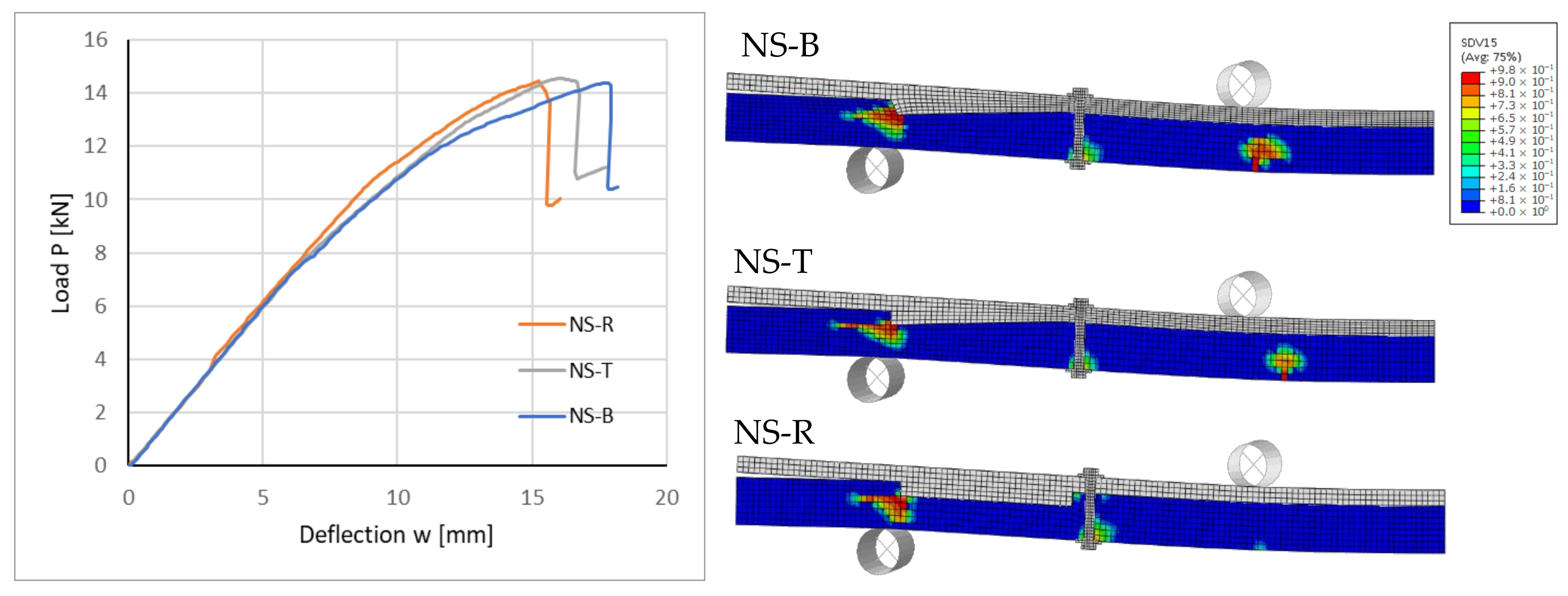
  • The birdsmouth notch increases the ductility of the slab compared to rectangular and triangular notches;
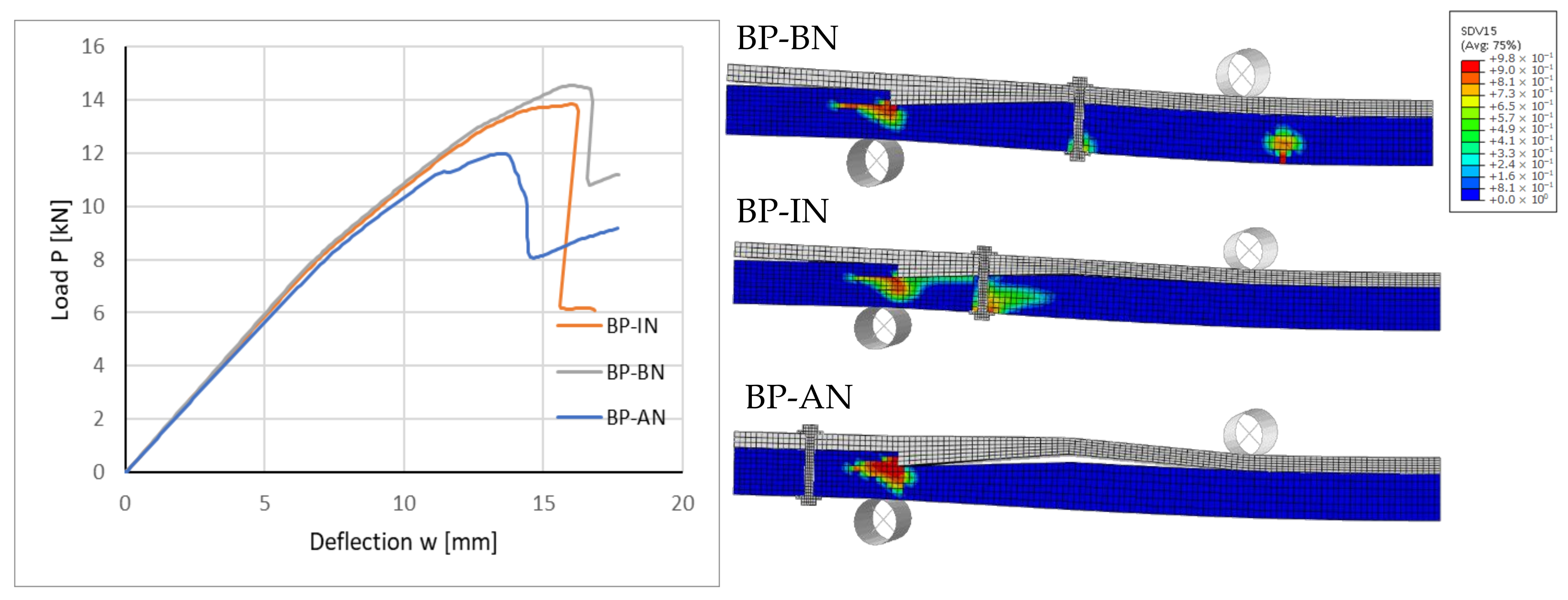
  • The position of the bolt can vary the load-bearing capacity up to 20%;
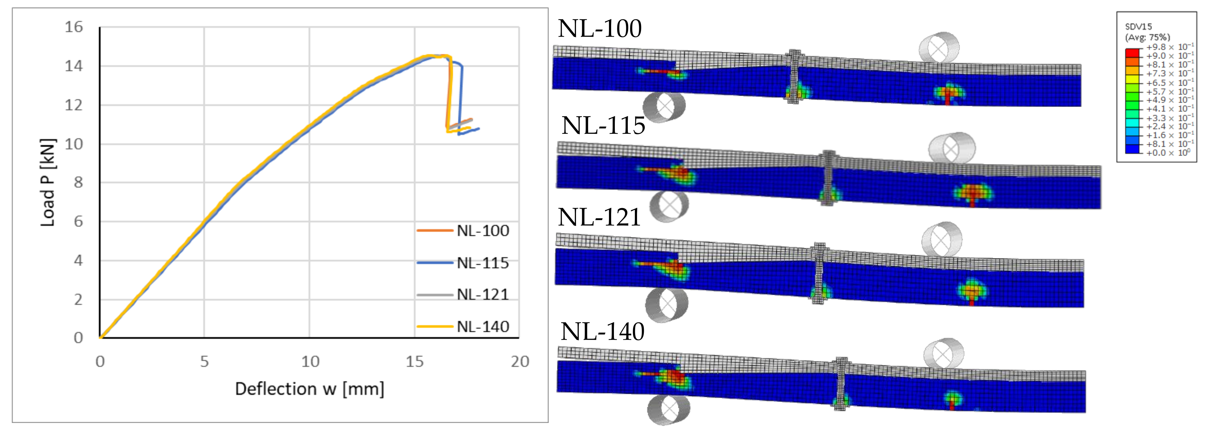
  • The length of the notch does not have a significant influence on the strength of the slab;
  • An increase in the timber length in front of the notch increases the bearing capacity of the shear connection;
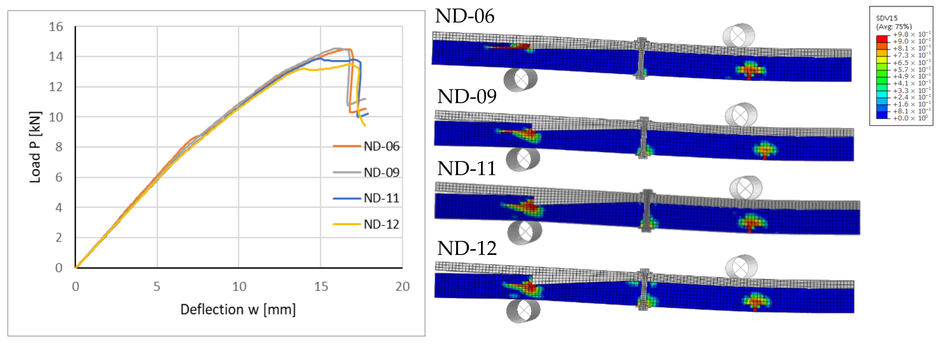
  • An excessive increase in the notch’s depth decreases the bending capacity of the slab;
This study contributes to the research field of DfD in TCC floors by featuring a straightforward, demountable shear connection with remarkable load-bearing behavior. Since the study was performed based on a downscaled model and limited specimens, more work is required to determine the load-bearing behavior, the influence of the frequency of notches and bolts, and the fabrication and deconstruction process in real-scale flexural and push-out tests. Also, since the used concrete in this study can vary from the conventional concrete, the impact of the concrete mixture must be investigated in future studies.

Author Contributions

Conceptualization, H.E., L.B.J. and D.W.; methodology, H.E. and L.B.J.; software, L.B.J.; validation, L.B.J. and D.W.; formal analysis, H.E. and L.B.J.; investigation, H.E., L.B.J. and D.W.; resources, H.E. and D.W.; data curation, H.E. and L.B.J.; writing—original draft preparation, H.E. and L.B.J.; writing—review and editing, D.W.; visualization, H.E.; supervision, D.W.; project administration, D.W.; funding acquisition, D.W. All authors have read and agreed to the published version of the manuscript.

Funding

This research is in the framework of the project Eco-Construction for Sustainable Developments (ECON4SD), supported by the program “Investissement pour la croissance et l’emploi”—European Regional Development Fund (2014–2020) (Grant agreement: 2017-02-015-15).

Data Availability Statement

The data presented in this study are available on request from the corresponding author. The data are not publicly available due to ongoing research project.

Conflicts of Interest

The authors declare no conflict of interest.

References

  1. Gálvez-Martos, J.-L.; Styles, D.; Schoenberger, H.; Zeschmar-Lahl, B. Construction and Demolition Waste Best Management Practice in Europe. Resour. Conserv. Recycl. 2018, 136, 166–178. [Google Scholar] [CrossRef] [Green Version]
  2. Kanters, J. Design for Deconstruction in the Design Process: State of the Art. Buildings 2018, 8, 150. [Google Scholar] [CrossRef] [Green Version]
  3. Allam, A.S.; Nik-Bakht, M. From Demolition to Deconstruction of the Built Environment: A Synthesis of the Literature. J. Build. Eng. 2023, 64, 105679. [Google Scholar] [CrossRef]
  4. Zhou, H.; Lu, W.; Lu, B.; Wang, L.; Bao, Y.; Zhang, J.; Chen, Z. Experimental and Numerical Analyses on the Fire Resistance of Timber–Concrete Composite Boards Using an Innovative Form of Partial Protection. Buildings 2023, 13, 725. [Google Scholar] [CrossRef]
  5. Ceccotti, A. Timber-Concrete Composite Structures. Timber Eng. 1995, 2, E13. [Google Scholar] [CrossRef]
  6. Dias, A.; Schänzlin, J.; Dietsch, P. Design of Timber-Concrete Composite Structures. In A State-of-the-Art Report by COST Action FP1402/WG; Shaker: Aachen, Germany, 2018; Volume 4. [Google Scholar]
  7. Monteiro, S.; Dias, A.; Lopes, S. Distribution of Concentrated Loads in Timber-Concrete Composite Floors: Simplified Approach. Buildings 2020, 10, 32. [Google Scholar] [CrossRef] [Green Version]
  8. Siddika, A.; Mamun, M.A.A.; Aslani, F.; Zhuge, Y.; Alyousef, R.; Hajimohammadi, A. Cross-Laminated Timber–Concrete Composite Structural Floor System: A State-of-the-Art Review. Eng. Fail. Anal. 2021, 130, 105766. [Google Scholar] [CrossRef]
  9. De Santis, Y.; Sciomenta, M.; Spera, L.; Rinaldi, V.; Fragiacomo, M.; Bedon, C. Effect of Interlayer and Inclined Screw Arrangements on the Load-Bearing Capacity of Timber-Concrete Composite Connections. Buildings 2022, 12, 2076. [Google Scholar] [CrossRef]
  10. Steinberg, E.; Selle, R.; Faust, T. Connectors for Timber–Lightweight Concrete Composite Structures. J. Struct. Eng. 2003, 129, 1538–1545. [Google Scholar] [CrossRef]
  11. Bao, Y.; Lu, W.; Yue, K.; Zhou, H.; Lu, B.; Chen, Z. Structural Performance of Cross-Laminated Timber-Concrete Composite Floors with Inclined Self-Tapping Screws Bearing Unidirectional Tension-Shear Loads. J. Build. Eng. 2022, 55, 104653. [Google Scholar] [CrossRef]
  12. Negrão, J.H.J. de O.; Maia de Oliveira, F.M.; Leitão de Oliveira, C.A.; Cachim, P.B. Glued Composite Timber-Concrete Beams.II: Analysis and Tests of Beam Specimens. J. Struct. Eng. 2010, 136, 1246–1254. [Google Scholar] [CrossRef]
  13. Clouston, P.; Civjan, S.; Bathon, L. Experimental Behavior of a Continuous Metal Connector for a Wood-Concrete Composite System. For. Prod. J. 2004, 54, 10. [Google Scholar]
  14. Xu, Q.; Wang, M.; Chen, L.; Harries, K.A.; Song, X.; Wang, Z. Mechanical Performance of Notched Shear Connections in CLT-Concrete Composite Floor. J. Build. Eng. 2023, 70, 106364. [Google Scholar] [CrossRef]
  15. Zhang, L.; Chui, Y.H.; Tomlinson, D. Experimental Investigation on the Shear Properties of Notched Connections in Mass Timber Panel-Concrete Composite Floors. Constr. Build. Mater. 2020, 234, 117375. [Google Scholar] [CrossRef]
  16. Boccadoro, L.; Zweidler, S.; Steiger, R.; Frangi, A. Bending Tests on Timber-Concrete Composite Members Made of Beech Laminated Veneer Lumber with Notched Connection. Eng. Struct. 2017, 132, 14–28. [Google Scholar] [CrossRef]
  17. Van Thai, M.; Ménard, S.; Elachachi, S.M.; Galimard, P. Performance of Notched Connectors for CLT-Concrete Composite Floors. Buildings 2020, 10, 122. [Google Scholar] [CrossRef]
  18. Yeoh, D.; Fragiacomo, M.; De Franceschi, M.; Buchanan, A.H. Experimental Tests of Notched and Plate Connectors for LVL-Concrete Composite Beams. J. Struct. Eng. 2011, 137, 261–269. [Google Scholar] [CrossRef]
  19. Mirdad, M.A.H.; Khan, R.; Chui, Y.H. Analytical Procedure for Timber−Concrete Composite (TCC) System with Mechanical Connectors. Buildings 2022, 12, 885. [Google Scholar] [CrossRef]
  20. Kuklík, P.; Nechanický, P.; Kuklíková, A. Development of Prefabricated Timber-Concrete Composite Floors. In Materials and Joints in Timber Structures; Aicher, S., Reinhardt, H.-W., Garrecht, H., Eds.; Springer: Dordrecht, The Netherlands, 2014; pp. 463–470. ISBN 978-94-007-7810-8. [Google Scholar]
  21. Yilmaz, S.; Demir, S.; Vural, N. Experimental Investigation of a Prefabricated Timber-Concrete Composite Floor Structure: Notched-Slab Approach. Adv. Concr. Constr. 2021, 12, 13–23. [Google Scholar] [CrossRef]
  22. Yeoh, D.; Fragiacomo, M. The Design of a Semi-Prefabricated LVL-Concrete Composite Floor. Adv. Civ. Eng. 2012, 2012, 626592. [Google Scholar] [CrossRef] [Green Version]
  23. Sebastian, W.; Webb, S.; Nagree, H.S. Orthogonal Distribution and Dynamic Amplification Characteristics of Partially Prefabricated Timber-Concrete Composites. Eng. Struct. 2020, 219, 110693. [Google Scholar] [CrossRef]
  24. Crocetti, R.; Sartori, T.; Tomasi, R. Innovative Timber-Concrete Composite Structures with Prefabricated FRC Slabs. J. Struct. Eng. 2015, 141, 04014224. [Google Scholar] [CrossRef]
  25. Crocetti, R.; Sartori, T.; Flansbjer, M. Timber-Concrete Composite Structures with Prefabricated FRC Slab. In Proceedings of the 11th World Conference on Timber Engineering, Trentino, Italy, 20–24 June 2010; Volume 1, pp. 121–130. [Google Scholar]
  26. Sartori, T.; Crocetti, R. Prefabricated Timber-Concrete Composite Floors. Eur. J. Wood Wood Prod. 2016, 74, 483–485. [Google Scholar] [CrossRef]
  27. Lukaszewska, E.; Johnsson, H.; Fragiacomo, M. Performance of Connections for Prefabricated Timber–Concrete Composite Floors. Mater. Struct. 2008, 41, 1533–1550. [Google Scholar] [CrossRef]
  28. Lukaszewska, E.; Fragiacomo, M.; Johnsson, H. Laboratory Tests and Numerical Analyses of Prefabricated Timber-Concrete Composite Floors. J. Struct. Eng. 2010, 136, 46–55. [Google Scholar] [CrossRef]
  29. Shi, B.; Zhu, W.; Yang, H.; Liu, W.; Tao, H.; Ling, Z. Experimental and Theoretical Investigation of Prefabricated Timber-Concrete Composite Beams with and without Prestress. Eng. Struct. 2020, 204, 109901. [Google Scholar] [CrossRef]
  30. Shi, B.; Liu, W.; Yang, H. Experimental Investigation on the Long-Term Behaviour of Prefabricated Timber-Concrete Composite Beams with Steel Plate Connections. Constr. Build. Mater. 2021, 266, 120892. [Google Scholar] [CrossRef]
  31. Ataei, A.; Bradford, M.A.; Valipour, H. Sustainable Design of Deconstructable Steel-Concrete Composite Structures. Procedia Eng. 2016, 145, 1153–1160. [Google Scholar] [CrossRef] [Green Version]
  32. Hosseini, S.M.; Mashiri, F.; Mirza, O. Research and Developments on Strength and Durability Prediction of Composite Beams Utilising Bolted Shear Connectors (Review). Eng. Fail. Anal. 2020, 117, 104790. [Google Scholar] [CrossRef]
  33. He, J.; Feng, S.; Vasdravellis, G.; Xin, H.; Correia, J.A.F.O.; Berto, F. Behaviour of the Lockbolt Demountable Shear Connector under Combined Shear and Tension Loading. Eng. Fail. Anal. 2022, 141, 106712. [Google Scholar] [CrossRef]
  34. Shamel Fahmy, A.; Mostafa Swelem, S.; Kamal Abdelaziz, M. Behavior of High-Strength Demountable Bolted Shear Connectors in Steel-Concrete Girders with Prefabricated Slabs. Alex. Eng. J. 2023, 70, 247–260. [Google Scholar] [CrossRef]
  35. Khorsandnia, N.; Valipour, H.; Schänzlin, J.; Crews, K. Experimental Investigations of Deconstructable Timber–Concrete Composite Beams. J. Struct. Eng. 2016, 142, 04016130. [Google Scholar] [CrossRef]
  36. Khorsandnia, N.; Valipour, H.; Bradford, M. Deconstructable Timber-Concrete Composite Beams with Panelised Slabs: Finite Element Analysis. Constr. Build. Mater. 2018, 163, 798–811. [Google Scholar] [CrossRef]
  37. Derikvand, M.; Fink, G. Deconstructable Connector for TCC Floors Using Self-Tapping Screws. J. Build. Eng. 2021, 42, 102495. [Google Scholar] [CrossRef]
  38. Derikvand, M.; Fink, G. Bending Properties of Deconstructable Cross-Laminated Timber-Concrete Composite Floor Elements. Wood Mater. Sci. Eng. 2022, 17, 253–260. [Google Scholar] [CrossRef]
  39. Dias, A.M.P.G.; Martins, A.R.D.; Simões, L.M.C.; Providência, P.M.; Andrade, A.A.M. Statistical Analysis of Timber–Concrete Connections—Mechanical Properties. Comput. Struct. 2015, 155, 67–84. [Google Scholar] [CrossRef]
  40. Premiumzemente. Available online: https://www.dyckerhoff.com/premiumzemente (accessed on 4 June 2023).
  41. DIN EN 196-1:1995-05; Prüfverfahren für Zement Teil 1: Bestimmung der Festigkeit. Comité Européen de Normalisation: Ville de Bruxelles, Belgium, 2005.
  42. MasterGlenium ACE 456. Available online: https://mbcc.sika.com/en-ae/products/masterglenium/masterglenium-ace-456 (accessed on 4 June 2023).
  43. Flaga, K.; Derkowski, W.; Surma, M. Concrete Strength and Elasticity of Precast Thin-Walled Elements. Cem. Wapno Beton 2016, 2016, 310–317. [Google Scholar]
  44. ILNAS-EN 338: 2016; Structural Timber—Strength Classes. Comité Européen de Normalisation: Ville de Bruxelles, Belgium, 2016.
  45. Šubic, B.; Fajdiga, G.; Lopatič, J. Bending Stiffness, Load-Bearing Capacity and Flexural Rigidity of Slender Hybrid Wood-Based Beams. Forests 2018, 9, 703. [Google Scholar] [CrossRef] [Green Version]
  46. Ceccotti, A. Composite Concrete-Timber Structures. Prog. Struct. Eng. Mater. 2002, 4, 264–275. [Google Scholar] [CrossRef]
  47. ILNAS-EN 1995-1-1:2004; Eurocode 5: Design of Timber Structures—Part 1-1: General—Common Rules and Rules for Buildings. Comité Européen de Normalisation: Ville de Bruxelles, Belgium, 2004.
  48. Gutkowski, R.M.; Goodman, J.R.; Pault, J.D.; Bodig, J. Tests and Analysis for Composite Action in Glulam Bridge Systems; The Engineering Foundation for Grant Rc-A-74-6; Colorado State University: Fort Collins, CO, USA, 1977; p. 49. [Google Scholar]
  49. Dias, A.M.P.G.; Helena, C.; Lopes, S.; Kuilen, J.W.G. Experimental Shear–Friction Tests on Dowel-Type Fastener Timber–Concrete Joints. In Proceedings of the 8th World Conference on Timber Engineering, Lahti, Finland, 14–17 June 2004. [Google Scholar]
  50. Rabbat, B.G.; Russell, H.G. Friction Coefficient of Steel on Concrete or Grout. J. Struct. Eng. 1985, 111, 505–515. [Google Scholar] [CrossRef]
  51. Koubek, R.; Dedicova, K. Friction of Wood on Steel; Linnaeus University, Faculty of Technology: Växjö, Sweden, 2014. [Google Scholar]
  52. SIMULIA. Abaqus 6.11 Theory Manual; Dassault Systèmes: Vélizy-Villacoublay, France, 2011; Chapter 4. [Google Scholar]
  53. Wee, T.H.; Chin, M.S.; Mansur, M.A. Stress-Strain Relationship of High-Strength Concrete in Compression. J. Mater. Civ. Eng. 1996, 8, 70–76. [Google Scholar] [CrossRef]
  54. Olsen, N.H.; Krenchel, H.; Shah, S.P. Mechanical Properties of High Strength Concrete. IABSE Rep. 1987, 55, 395–400. [Google Scholar] [CrossRef]
  55. Carreira, D.J.; Chu, K.-H. Stress-Strain Relationship for Plain Concrete in Compression. ACI J. Proc. 1985, 82, 797–804. [Google Scholar] [CrossRef]
  56. Federation Internationale du Beton; Beverly, P. Fib Model Code for Concrete Structures 2010; Ernst & Sohn: Berlin, Germany, 2013; ISBN 978-3-433-60421-2. [Google Scholar]
  57. Eslami, H.; Jayasinghe, L.B.; Waldmann, D. Nonlinear Three-Dimensional Anisotropic Material Model for Failure Analysis of Timber. Eng. Fail. Anal. 2021, 130, 105764. [Google Scholar] [CrossRef]
  58. Hoffman, O. The Brittle Strength of Orthotropic Materials. J. Compos. Mater. 1967, 1, 200–206. [Google Scholar] [CrossRef]
  59. Hill, R. A Theory of the Yielding and Plastic Flow of Anisotropic Metals. Proc. R. Soc. Lond. Ser. A Math. Phys. Sci. 1948, 193, 281–297. [Google Scholar] [CrossRef]
Figure 1. Longitudinal cross-section of a TCC beam with 3 different shear connections: dowels, notches, and glued-in-plate. Figure from Mirdad et al. [19].
Buildings 13 01763 g001
Figure 2. Conceptual design of the novel demountable timber–concrete composite floor system.
Buildings 13 01763 g002
Figure 3. Design of the downscaled novel TCC slab (Dimensions are in mm).
Buildings 13 01763 g003
Figure 4. Comparison of the strength of the different concrete mixtures.
Buildings 13 01763 g004
Figure 5. Experimental setup.
Buildings 13 01763 g005
Figure 6. LVDT displacement sensors for (a) slip measurement at end-span and (b) deflection measurement at mid-span.
Buildings 13 01763 g006
Figure 7. Results from the experiment: (a) Load-deflection; (b) Normalized load-deflection.
Buildings 13 01763 g007
Figure 8. Failure modes in timber: (a) Horizontal shear failure at the notch; (b) Bending failure at mid-span.
Buildings 13 01763 g008
Figure 9. Analytical load-deflection graphs for no composite, full composite, and experimental composite action.
Buildings 13 01763 g009
Figure 10. The geometry of the modeled bending experiment in Abaqus.
Buildings 13 01763 g010
Figure 11. (a) Stress–strain response of the concrete in compression; (b) Post-failure crack opening response of the concrete under tensile stress.
Buildings 13 01763 g011
Figure 12. Load-deflection result from the FE model compared to the experimental results.
Buildings 13 01763 g012
Figure 13. Stress distribution of the composite slab at failure load (values in MPa).
Buildings 13 01763 g013
Figure 14. Damage evolution in the timber part at (a) P/Pu = 0.67; (b) P/Pu = 0.95; (c) P = Pu.
Buildings 13 01763 g014
Figure 15. Parameters of the shear connection considered in the parametric study.
Buildings 13 01763 g015
Figure 16. Results of the parametrical study.
Buildings 13 01763 g016
Figure 17. Influence of the shape of the notch on load deflection and failure of the TCC slab.
Buildings 13 01763 g017
Figure 18. Influence of the position of the bolt on load deflection and failure of the TCC slab.
Buildings 13 01763 g018
Figure 19. Influence of the length of the notch on load deflection and failure of the TCC slab.
Buildings 13 01763 g019
Figure 20. Influence of the depth of the notch on load deflection and failure of the TCC slab.
Buildings 13 01763 g020
Figure 21. Influence of the timber length in front of the notch on load deflection and failure of the TCC slab.
Buildings 13 01763 g021
Table 1. Chosen mixture specifications.
ItemAmount [kg/m3]
Sand1108
Binder1108
Water169
Superplasticizer13.4
Total2399
Table 2. Mechanical properties of the special mixture for 28-day-old specimens.
Compression Strength [MPa]Modulus of
Elasticity [GPa]
Tensile Splitting Strength [MPa]
Range105.5–113.143.9–46.06.9–7.8
Average109.145.07.5
SD2.81.10.5
COV [%]2.62.36.7
Table 3. Timber C24 characteristic values according to EN 338:2009.
Strength Properties [MPa]
Bending24
Tension parallel14
Tension perpendicular0.4
Compression parallel21
Compression perpendicular2.5
Shear4
Stiffness Properties [MPa]
Mean Modulus of Elasticity parallel to grain direction11,000
Mean Modulus of Elasticity perpendicular to grain direction370
Mean Shear Modulus690
Mean density [kg/m3]420
Table 4. Summary of the experimental results.
At Ultimate LoadAt 30% of the Ultimate Load Effective Rigidity
Specimens No.Pu [kN]wu [mm]ku [kN/mm]P0.3 [kN]w0.3 [mm]k0.3 [kN/mm](EI)eff
[kN.m2]
T119.519.41.015.94.61.2911.8
T214.815.00.994.44.11.0910.0
T317.518.00.975.34.61.1310.4
T413.314.90.894.04.20.958.7
T515.219.50.784.64.80.948.6
T617.815.91.125.34.21.2611.5
Average16.317.10.964.94.41.1110.2
SD2.101.950.100.630.270.131.22
CV%12.9%11.4%10.8%12.9%6.2%12.0%12.0%
Table 5. Composite action of the slab.
Composite Connectionγcγt(EI)eff [kN·m2]
No composite014.8
Experimented connection0.23110.2
Full composite1117.8
Table 6. Material properties of timber for FE modeling.
Elasticity Parameters
E1 [MPa]E2 = E3 [MPa]G23 [MPa]G12 = G13 [MPa]ν23ν12 = ν13
11,000370606900.50.45
Strength parameters
σ1c [MPa]σ2c = σ3c [MPa]σ1t [MPa]σ2t = σ3t [MPa]σ23 [MPa]σ12 = σ13 [MPa]
546.9360.70.53.5
Hardening parameters
h [MPa]
6436
Fracture energies
G1t, f [N/mm]G2t,f [N/mm]G3t, f [N/mm]
100.20.2
Table 7. Parameters in the parametric models.
ModelNotch Depth [mm]Notch Length [mm]Notch Head [mm]Notch ShapeBolt Position
ND—066121116TriangularBN
ND—099121116TriangularBN
ND—1111121116TriangularBN
ND—1212121116TriangularBN
NL—1009100116TriangularBN
NL—1159115116TriangularBN
NL—1219121116TriangularBN
NL—1409140116TriangularBN
NH—1009121100TriangularBN
NH—1089121108TriangularBN
NH—1169121116TriangularBN
NH—1409121140TriangularBN
NS—B9121116BirdsmouthBN
NS—T9121116TriangularBN
NS—R9121116RectangularBN
BP—IN9121116TriangularIN
BP—BN9121116TriangularBN
BP—AN9121116TriangularAN
Disclaimer/Publisher’s Note: The statements, opinions and data contained in all publications are solely those of the individual author(s) and contributor(s) and not of MDPI and/or the editor(s). MDPI and/or the editor(s) disclaim responsibility for any injury to people or property resulting from any ideas, methods, instructions or products referred to in the content.

