Article

The Assessment and Retrofitting of Cultural Heritage—A Case Study of a Residential Building in Glina

1
Department for Structures, Faculty of Civil Engineering, University of Zagreb, 10000 Zagreb, Croatia
2
PRONA—GRAD, 10090 Zagreb, Croatia
*
Author to whom correspondence should be addressed.
Buildings 2023, 13(7), 1798; https://doi.org/10.3390/buildings13071798
Submission received: 7 June 2023 / Revised: 3 July 2023 / Accepted: 12 July 2023 / Published: 14 July 2023

Abstract

:
The focus of the study is on the renovation of a specific case study, which is a 19th century building under cultural heritage protection. It highlights the particular challenges faced by civil engineers in the structural renovation of buildings that are under heritage protection. Preserving the identity of these buildings limits the available methods for strengthening their seismic capacity. At the beginning, information about the seismic activity and the different post-earthquake evaluation procedures are presented to identify the damage and take appropriate further steps. Then, basic information about the building is given and supported by graphic attachments. In the following, the methods and materials are explained, focusing on in situ testing with the semi-destructive flat-jack method and the analysis of the structure with the nonlinear method implemented in the software. Subsequently, the obtained results are presented and discussed, accompanied by graphics. An approach for strengthening the structure is presented, which includes a combination of traditional methods and innovative solutions suitable for the preservation of cultural heritage. The discussion and conclusions emphasize the importance of assessing and retrofitting existing masonry structures due to their vulnerability, especially in earthquake-prone areas. Finally, this article also provides insights into the local context, cultural significance, and historical background of the building, along with the specific retrofitting solutions employed to address its unique requirements.

1. Introduction

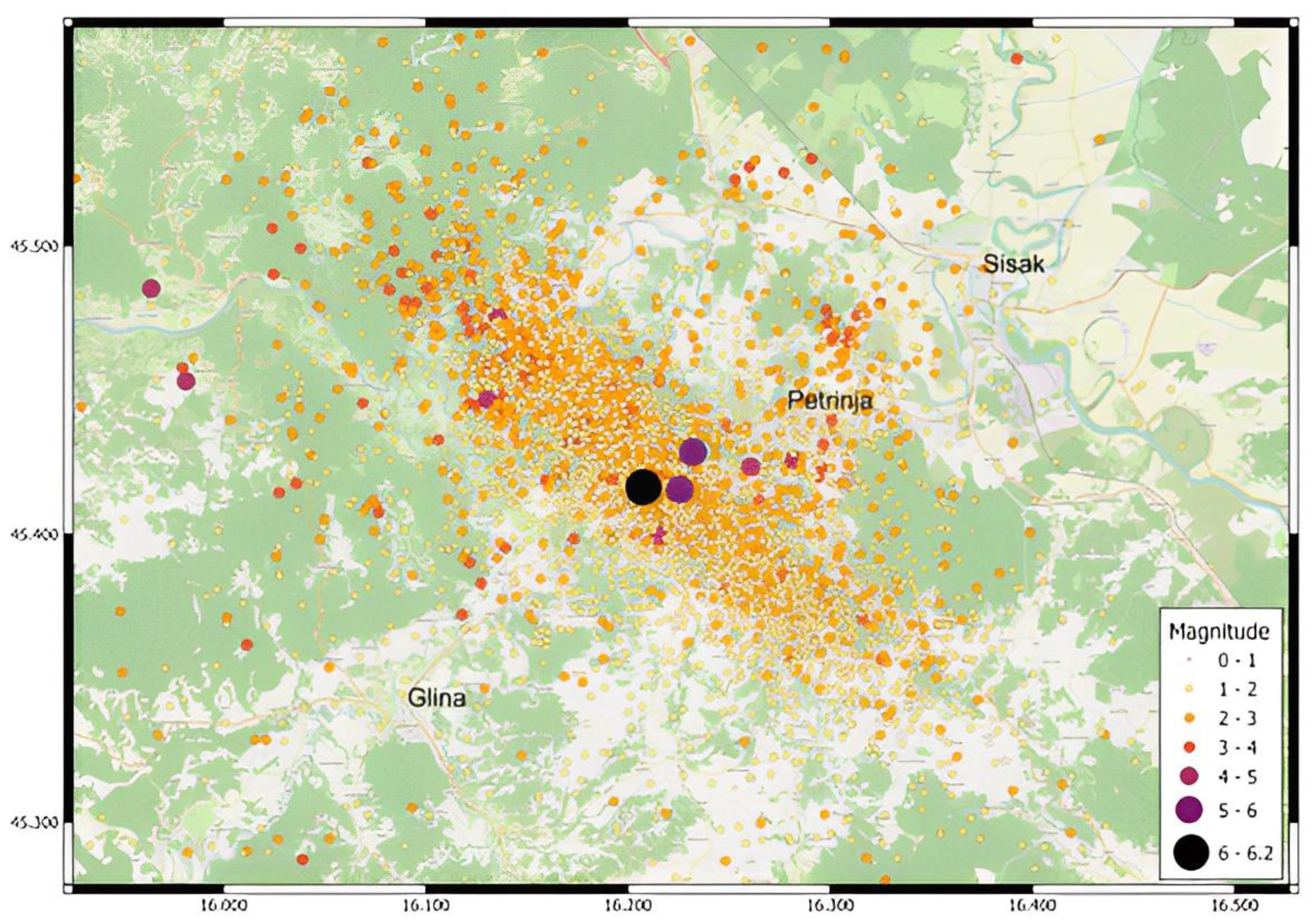
On 28 December 2020, at 6 h and 28 min, a strong earthquake with an epicenter near Petrinja occurred, with an intensity of 5 degrees on the Richter scale; this preceded a devastating earthquake on 29 December 2020, at 12 h and 19 min, with an epicenter 5 km southwest of Petrinja, at a depth of 11.5 km and a magnitude of 6.2 on the Richter scale (the intensity at the epicenter was VIII-IX degrees on the EMS scale) (Figure 1). After the earthquake, until today, the area of the City of Petrinja and its surroundings, including Glina and Sisak, have been hit by a series of minor and medium earthquakes, i.e., there was increased tectonic activity that resulted in a series of smaller earthquakes. The greatest material damage was recorded in the center of the town of Petrinja [1]. The earthquakes in Petrinja were also significantly felt in the area of Zagreb, which “swayed” more due to the greater epicentral distance that enabled the development of surface waves; these effects were felt more strongly than those of a recent Zagreb earthquake in 2020 [2].
It is well known that traditional masonry structures in Europe are vulnerable to earthquakes due to their inherent characteristics, such as inappropriate or nonexistent connections between wall and floor and roof structures, the absence of vertical and horizontal confining elements, uneven stiffness distribution, and poor load-bearing capacity [3,4,5]. The lack of flexibility and the inability to absorb seismic energy make masonry structures highly susceptible to damage during seismic events [6]. Additionally, most of the buildings in the city center have an expired service life, which means the degradation of their mechanical properties should be taken into account [7].
Additionally, the construction methods and materials used in masonry structures often do not meet modern seismic design standards. The seismic vulnerability [8] of masonry structures is also influenced by factors such as quality of construction, maintenance, and renovation history. As a result, many historic masonry structures in Europe are at risk of collapse during earthquakes. Therefore, it is essential to assess and retrofit existing masonry structures to improve their seismic resistance and ensure their safety during seismic events.
Figure 1. Map of the epicenter of the earthquake near Petrinja in the period from 29 December 2020 at 12:19 p.m. to 30 December 2020 at 10:00 p.m. [9].
Buildings 13 01798 g001
To do so, thorough experimental tests and detailed geometrical and structural surveys are needed to overcome complex mechanical and geometrical issues. Additionally, we need to model a reliable simulation of the mechanical response of existing masonry buildings. Firstly, to accomplish this, well-established assessment procedures are required. An essential part of these assessment procedures is the reduction of epistemic uncertainty through gathering additional information [10]. This type of uncertainty can be reduced to a certain point, unlike aleatory uncertainties, which are defined as internal randomness of phenomena [11]. To minimize uncertainties, various inspection techniques are feasible, such as visual assessment, destructive, semi-destructive, and non-destructive methods (NDT), as well as collecting data with structural health monitoring (SHM) [12]. In the field of collecting data, some new technologies such as drone imaging and laser scanning could aid in completing a comprehensive assessment process [13]. Laser scanning and unmanned aerial vehicles (UAV) can be used in crisis management for damage detection, crack identification, and assessment of cultural heritage. Producing digital twins [14,15] is also vital for preserving the current state of the building, and this method can also be used for reconstruction purposes.
Understanding and identifying the key structural vulnerabilities of a building requires a precise evaluation of its seismic performance. Simulating the dynamic behavior of masonry structures accurately is crucial for this purpose [16]. In terms of analysis approaches, the response of masonry structures can be investigated in two main ways [17]: incremental-iterative analyses and limit analysis-based solutions. Incremental-iterative analyses are classified as either nonlinear static (pushover) analysis or nonlinear dynamic (time history) analysis. On the other hand, limit analysis-based solutions are either a lower-bound limit analysis (a static theorem) or an upper-bound limit analysis (a kinematic theorem). Regarding modelling strategies for masonry structures, four different categories are defined: block-based models [18], continuum models [18], macro-element models [19], and geometry-based models [20]. Each modelling strategy has its limitations and specific area of application. Therefore, the most suitable modelling strategy depends on the features and the complexity of the structure under investigation, the output required, the data available, and the expertise level.
This paper presents the procedure of a detailed inspection of a building under cultural heritage protection that was damaged in the 2020 Petrinja earthquake. An incremental-iterative analysis, i.e., a nonlinear static (pushover) analysis was the approach used for the renovation of the case study, while a macro-element model, that is, the equivalent frame model, was used as the modelling strategy [21]. In the sections below, the analysis approach and modelling strategies for the renovation of the case study are presented in detail, as well as the assessment procedure. This paper also shares the valuable lessons learned from the case study, including successes, failures, and practical recommendations for future retrofitting projects involving cultural heritage buildings. These insights can inform and guide professionals in the field, and contribute to the development of guidelines and standards for the conservation and retrofitting of similar structures.

2. The Case Study

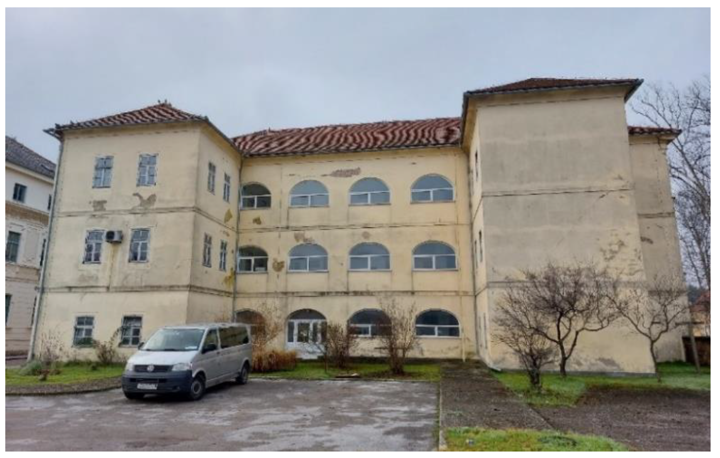
The case study building (Figure 2 and Figure 3), which is the subject of an ongoing condition assessment study, was inspected after a devastating series of earthquakes in Petrinja and its surroundings. The subject of this study is an isolated structure located at Trg bana Josipa Jelačića 21 in Glina. The building is a combined private and public property, and is a protected individual cultural asset of the Registry of Cultural Assets of the Republic of Croatia. The available existing documentation of the building shows that the building dates back to the 19th century. After a thorough reconstruction, the building took on its present form in 2000.
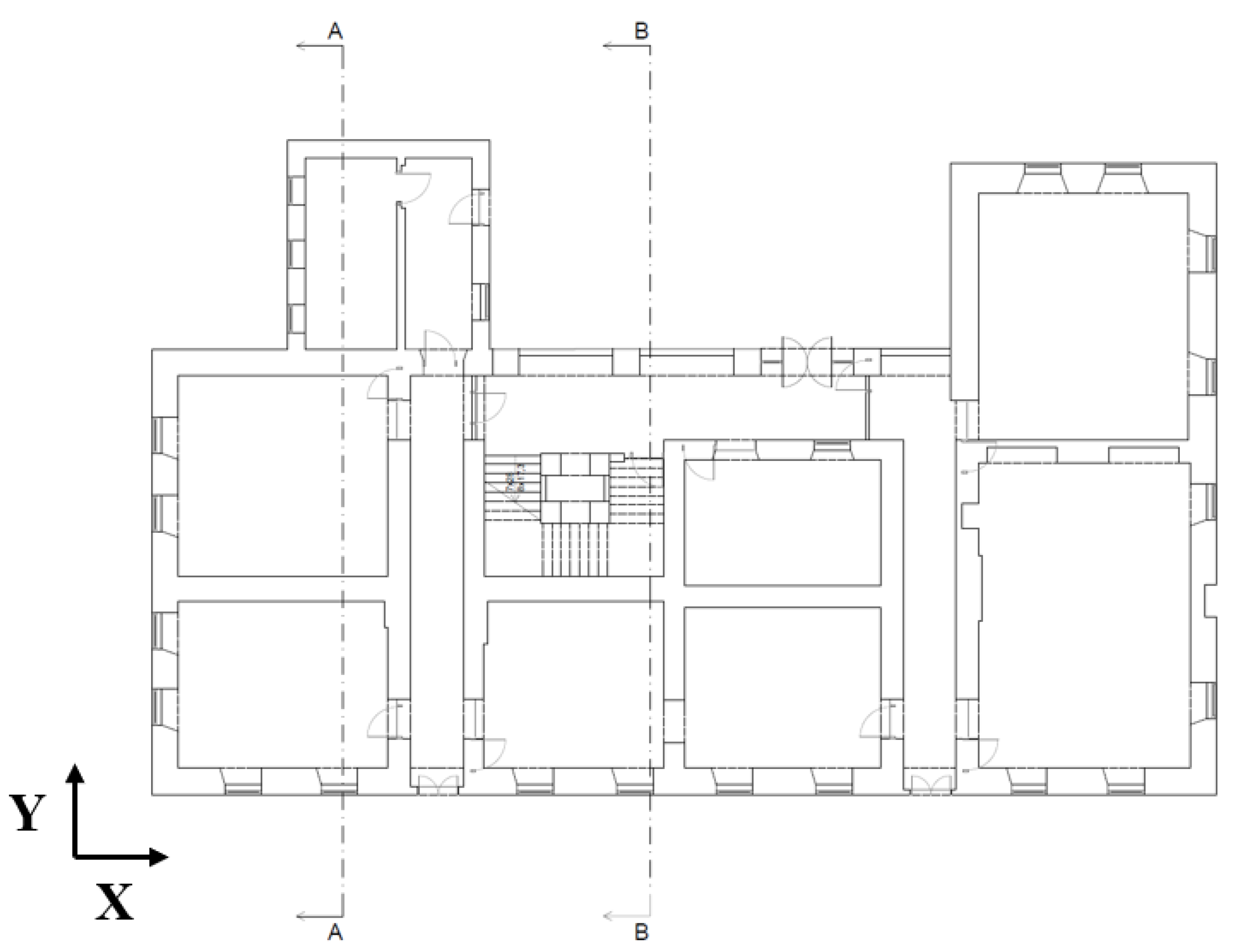
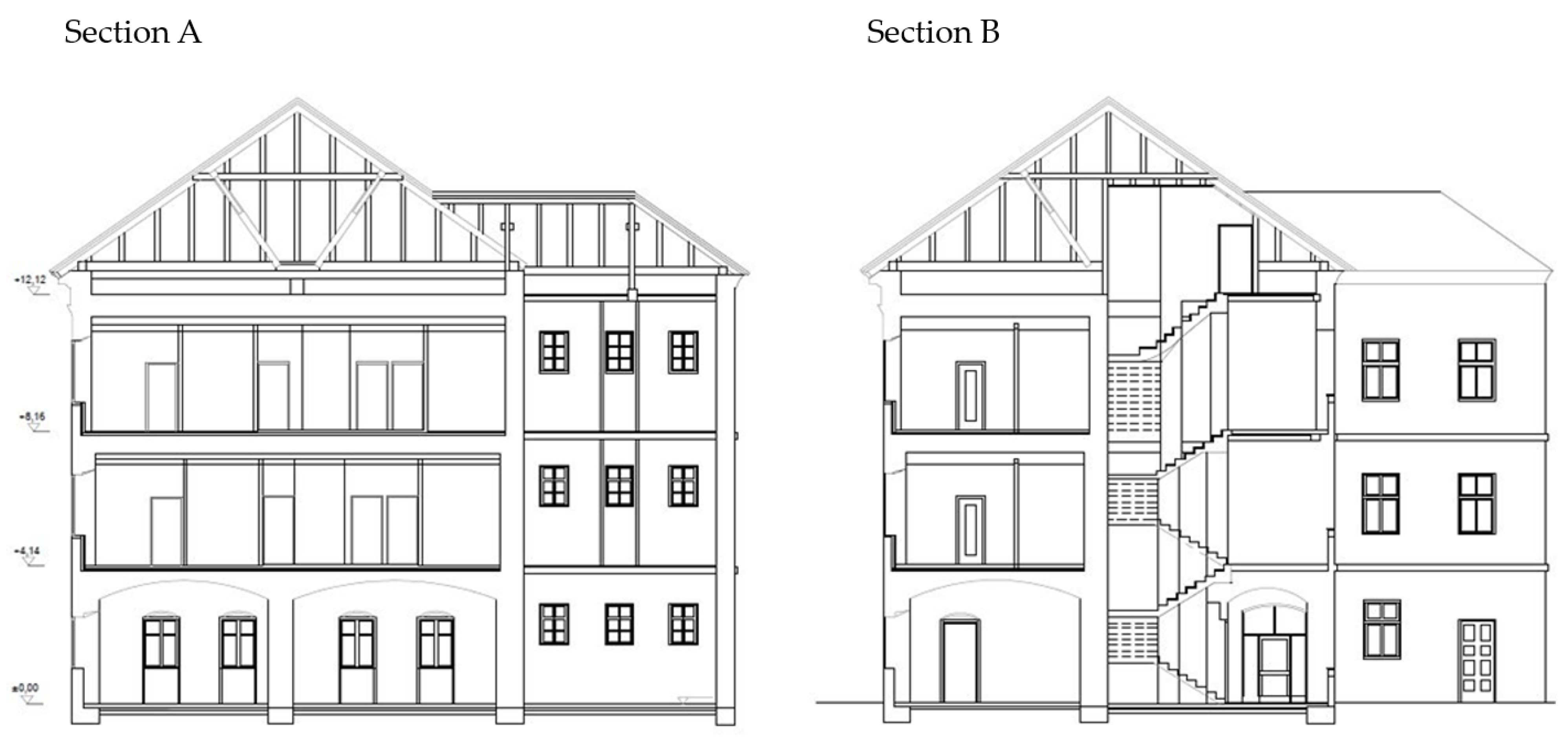
The building has a “U” shaped plan (Figure 4 and Figure 5). The main orientation, that is, the longer side of the building, is in the north-west–south-east direction. The external dimensions of the building are about 13.4 × 32 m, with two wings, one 6.2 × 6.1 m and the other 5.7 × 8.0 m. The total height of the building is 17 m. The floor plan of each storey is 514 m2. The building consists of a ground floor, first and second floors, and an attic (Figure 6). The building initially served as an educational institution (gymnasium), while today, it is used for residential and commercial purposes. The condition of the building before the earthquake was satisfactory, and the building was regularly maintained. The last reconstruction of the building was carried out in 2000. The building is built of solid brick of the old format (29 × 14 × 7 cm), as was used at the end of the 19th century. The thickness of the load-bearing walls varies within floors, and ranges between 45–75 cm. On the ground floor, the thickness is 75 cm. On the first floor, it varies from 65 cm to 45 cm, and the thickness decreases with height; on the 2nd floor, the thickness is 45 cm, and the partitioning walls are 20–30 cm thick. The floor structures differ on each storey. The floor structure of the ground floor consists of masonry vaults, except for the floor structure located in the wing, which is a semi-precast masonry/concrete floor system (with a Fert ceiling). On the first floor, a semi-precast masonry/concrete floor system (with a Fert ceiling) and timber floors with a concrete layer are found. The floor structure of the second floor consists of timber floors and Fert ceilings.

3. Methods and Materials

3.1. Assessment Procedure

Shortly after the earthquake, an assessment procedure was devised for rapid, preliminary assessment of buildings damaged in the earthquake [17]. The idea was to assess the usability of all damaged buildings without further endangering engineers in the field, as some buildings were heavily damaged. This type of assessment also provided preliminary feedback about the structures to their owners and occupants. Following a quick visual inspection of the load-bearing elements and deciding on the level of damage, each building was classified into one of six possible categories: U1, Usable without limitations (green label); U2, Usable with recommendations of 25 (green label); PN1, Temporarily unusable—detailed inspection needed (yellow label); PN2, Temporary unusable—emergency interventions needed (yellow label); N1, Unusable due to external impacts (red label); and N2, Unusable due to damage (red label) [22].
A rapid, preliminary assessment of the building was carried out on 31 December 2020. The building was classified as temporarily unusable (NP, yellow label) with a recommendation of urgent repair. The following recommendations were given: urgent repair of the roof, the removal of damaged chimneys, the remediation of moisture in the foundations, and the fastening of cornices at the corners. A further detailed assessment, as presented below, was also recommended.

3.2. Detailed Assessment Results

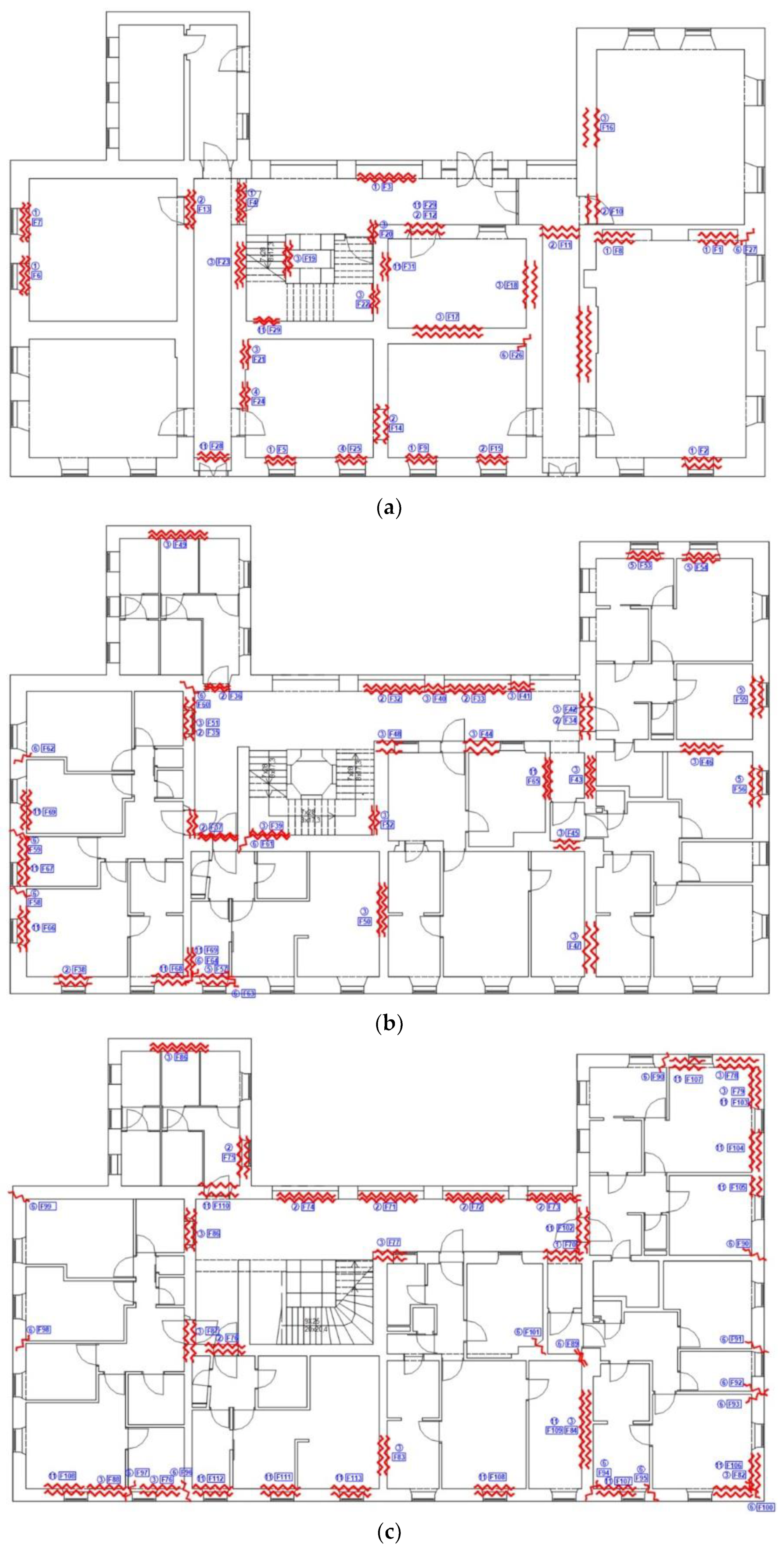
After a rapid inspection, a detailed inspection of the building was carried out in May 2022. All instances of damage, structural and non-structural (Figure 7), were photographed and described in reports on the floors of the building and the individual rooms in which they are located, and proposed measures for their repair were given. A detailed recording of the existing condition was also made for the purpose of creating digital floor plans of the building.
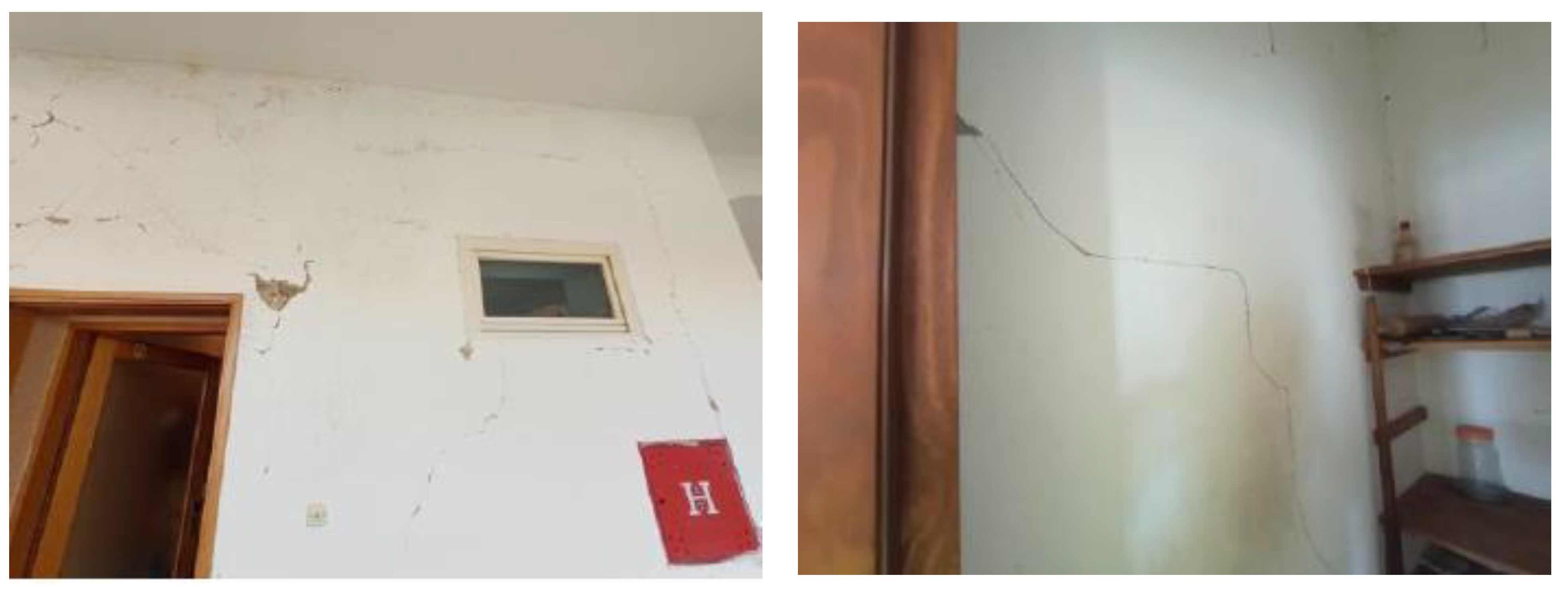
Detailed inspections of the residential building (former gymnasium building) revealed the following recorded instances of damage: on the ground floor, there is visible damage in the form of cracks in the wall coverings (Figure 8), arches, vaults and ceilings, as well as separation and localized falling off of the plaster. Minor local damage to structural elements (walls, columns, and arches) is also visible. Damage is visible on all floors in the form of cracks and falling plaster on the walls. Minor local damage to the walls is also visible, and there are locally visible cracks at the junctions of load-bearing walls and ceilings (Figure 9). At the edges of the building, oblique cracks are visible on the load-bearing walls, and can also be seen on the facade of the building. In addition to the previously documented damage to the construction elements of the building, damage to other elements was observed. The partition walls are mostly damaged. Other instances of damage include the chipping of plaster on structural and non-structural elements, damage to the finishing coverings on the walls and floors, and the collapse of part of the cornice and other decorative elements (Figure 10). The roof was damaged in several places, and the roof covering near the chimneys collapsed (Figure 11).
Based on the detailed assessment, the entirety of the building necessitates rehabilitation and retrofitting measures. Subsequently, it is imperative to conduct a comprehensive examination encompassing both static and dynamic analyses of the existing structural conditions. Before that, it is necessary to carry out investigative work to determine the characteristics of the walls and other necessary data for the analysis of the structure.

3.3. In-Situ Tests

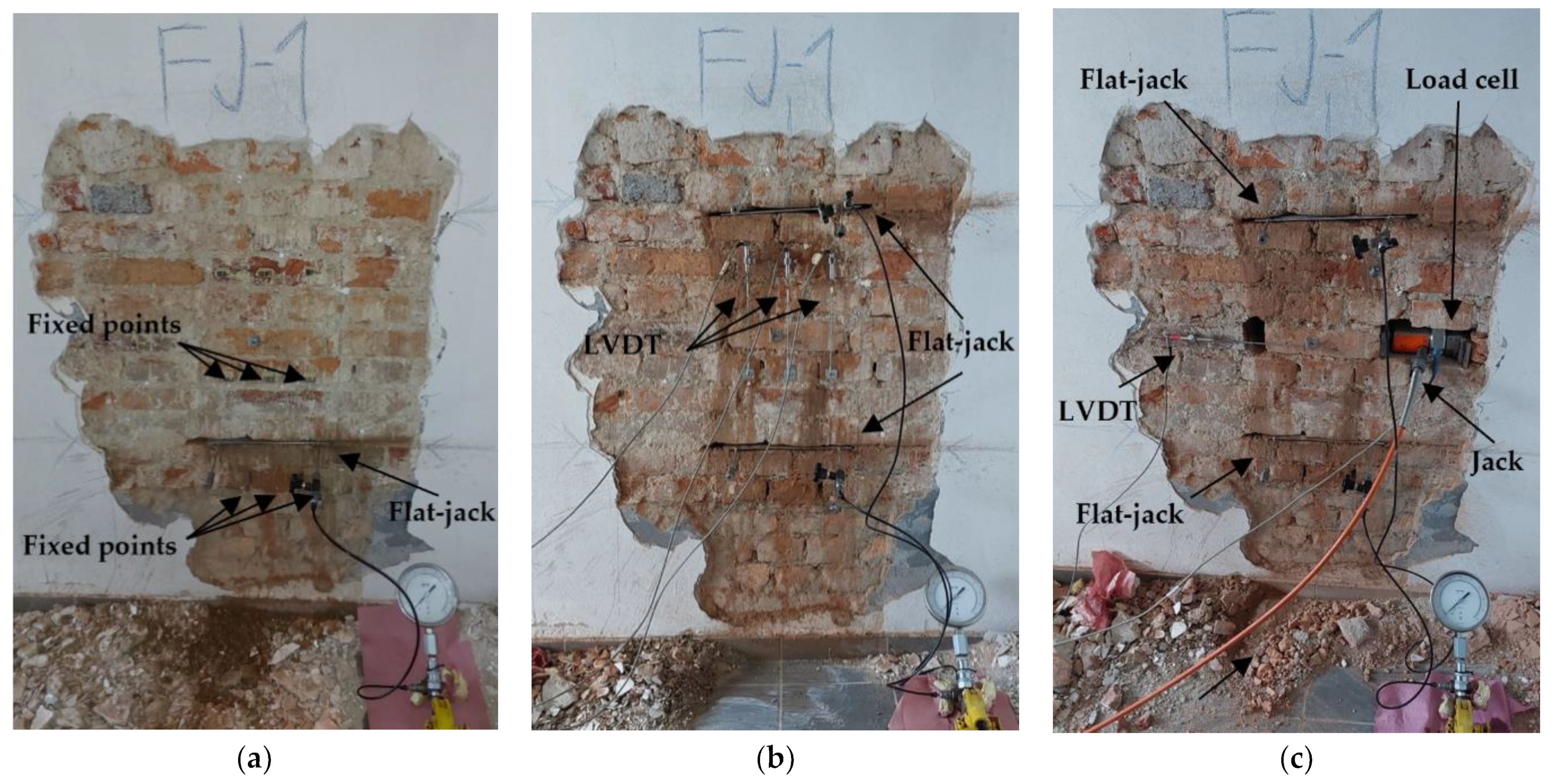
The building in question is two centuries old, and documentation of the original project is very scarce. In such existing structures, the quality of the material degrades over time, especially if it is not protected from the weather. In earthquake-prone areas, such conditions are additionally unfavorable, considering the inherent weaknesses of URM structures, such as high mass, low ductility, and energy dissipation [23]. Therefore, it is necessary to perform in situ testing of the masonry [24] as part of the assessment process. In this case study, a well-known semi-destructive method for masonry testing was used. The method mentioned is the flat-jack method. Since there are no guidelines within the European standards, the test can be performed following the guidelines given in the ASTM [25] and RILEM [26] standards. The method is divided into three phases, and provides results on the vertical stress state, the modulus of elasticity, and the shear strength of the masonry (Figure 12). Experiences from an extensive test campaign conducted after the recent devastating earthquakes in 2020 in Croatia are presented in [27]. The results from that campaign are presented in [28].
The principle of the single flat-jack test is to partially relieve the compressive stress in the wall by removing the mortar from the horizontal bed joint. This is achieved by making the opening with an eccentric circular saw. The stress is then compensated by means of a flat-jack inserted in the opening. The stress is gradually increased until the original stress and strain state is established, which is verified by measuring the displacements perpendicular to the opening. Measurements are made with a portable extensometer, and fixed measurement points glued to the bricks can be seen in Figure 12a. The results of the single flat-jack tests are shown in Table 1.
To determine the stress–strain behavior of masonry in compression and the modulus of elasticity of masonry, it is necessary to use another flat-jack placed above the first one (a double flat-jack test). Flat-jacks are inserted into parallel horizontal openings and pressure is applied gradually. In this phase, the displacement gauges (LVDTs) are placed vertically between the flat-jacks, as in Figure 12b. Simultaneously with the application of vertical pressure with the flat-jacks, the displacement is measured (Figure 13), which allows the stress–strain behavior and modulus of elasticity to be determined. For reference, see [27]. The resulting values for the double flat-jack tests are listed in Table 2.
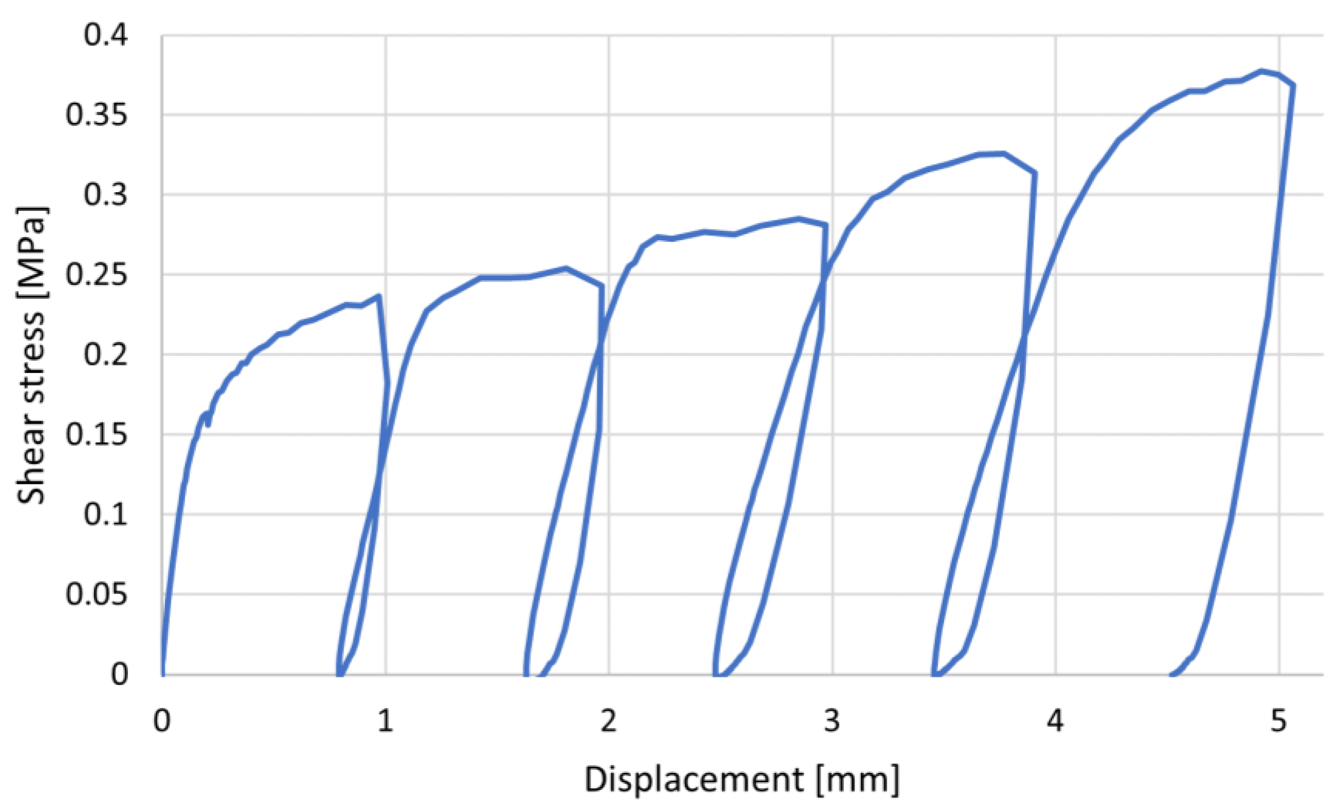
After the double flat-jack test, the shear (shove) test follows in the same location. Both flat-jacks with an additional horizontal hydraulic jack are used for this test (Figure 12c). The displacement gauges used in the previous phases are removed and a horizontal displacement gauge is mounted. In this phase, a horizontal brick (oriented so that a mayor dimension of the brick is parallel to the wall) is pushed until failure, that is, until it slips. This process is repeated for several vertical stress levels (Figure 14). Flat-jacks allow the control of the vertical stress at the test location. As a result, this provides the relationship between the shear stress and the vertical compressive stress. From this relationship, a best-fitting line can be drawn. The angle of this line represents the coefficient of friction, while the intersection with the vertical axis represents the initial shear strength of the masonry. The results of this test phase are shown in Table 3.
The results show that the quality of the masonry is relatively good, as the values obtained are within the expected range for buildings from this period of construction. Further non-destructive testing methods [29,30] can be used to validate the results. For example, in determining the modulus of elasticity, the sonic method has proven to be potentially useful. Another nondestructive method based only on visual inspection provides an approximate range of values for the shear strength, compressive strength, and modulus of elasticity of the masonry. This is the MQI method, which is explained in more detail in [31].

4. Structural Strengthening

After the earthquake, the Law on the Reconstruction of Earthquake-Damaged Buildings in the City of Zagreb, Krapina-Zagorje County, Zagreb County, Sisak-Moslavina County and Karlovac County [32] was passed. It provided a legal framework for post-earthquake rehabilitation. The law in question established four renovation levels based on factors such as the extent of damage, the building’s purpose, and the investor’s financial capacity. Level 1 focuses on restoring the structure’s original resistance from prior to the earthquake, while levels 2, 3, and 4 aim to achieve satisfactory earthquake resistance for a specified return period. The law specifies the distribution of renovation costs, with 60% covered by the Republic of Croatia using the state budget, 20% by the counties, and the remaining 20% by the owners (excluding finishings like façade installation, parquet, plastering, and painting, which are entirely financed by the owners).
The building In question is, as already mentioned, under cultural heritage protection, and it was built at a time when seismic regulations had not yet been issued. This means its structural system does not have sufficient seismic resistance [33]. To achieve this, intrusive and detailed interventions are necessary, such as construction of a new replacement structural system (shotcrete). The construction of a new structural system would violate the cultural identity of the building; therefore, a renovation to level 3 was proposed in agreement with the investor. For level 3, the relevant return period is 225 years.
To assess the seismic resistance of the structure, a pushover analysis has been carried out. This is a nonlinear static method, meaning it considers the nonlinear properties of the material and the redistribution of the forces in the structure. The method is suitable for the evaluation of existing structures, as it helps to identify potential weaknesses or deficiencies in structural systems. Additionally, it offers a reasonable balance between accuracy and computational efficiency. The basic assumption of the method is that the structure vibrates in the first mode, which is the main drawback of the method, because it is mainly applicable to regular buildings that have a dominant response in the first mode of vibration. It does not provide reliable results for tall and irregular buildings. A monotonically increasing static load represents the distribution of forces expected during a seismic event. The analysis is performed incrementally, starting from the linear elastic response and gradually introducing nonlinear behavior. At each increment, the structural response is calculated by considering the equilibrium between the applied loads and internal forces. As the structure exhibits nonlinear behavior, the load distribution within the structure is likely to change. The structure was modelled in the software 3Muri [34], which applies macro-element approach. The macro-element approach discretizes masonry elements to primary vertical elements (piers) and secondary horizontal elements (spandrels). The longitudinal and transversal walls are connected to each other and to the floor structures by rigid nodes. As has already been mentioned, the floor structures vary on each storey. On the ground and first floor, the floor structures are set as rigid diaphragms, while on the second floor, rigid and flexible diaphragms are modelled. Although the connections are set as rigid, the load transfer differs depending on the diaphragm type.
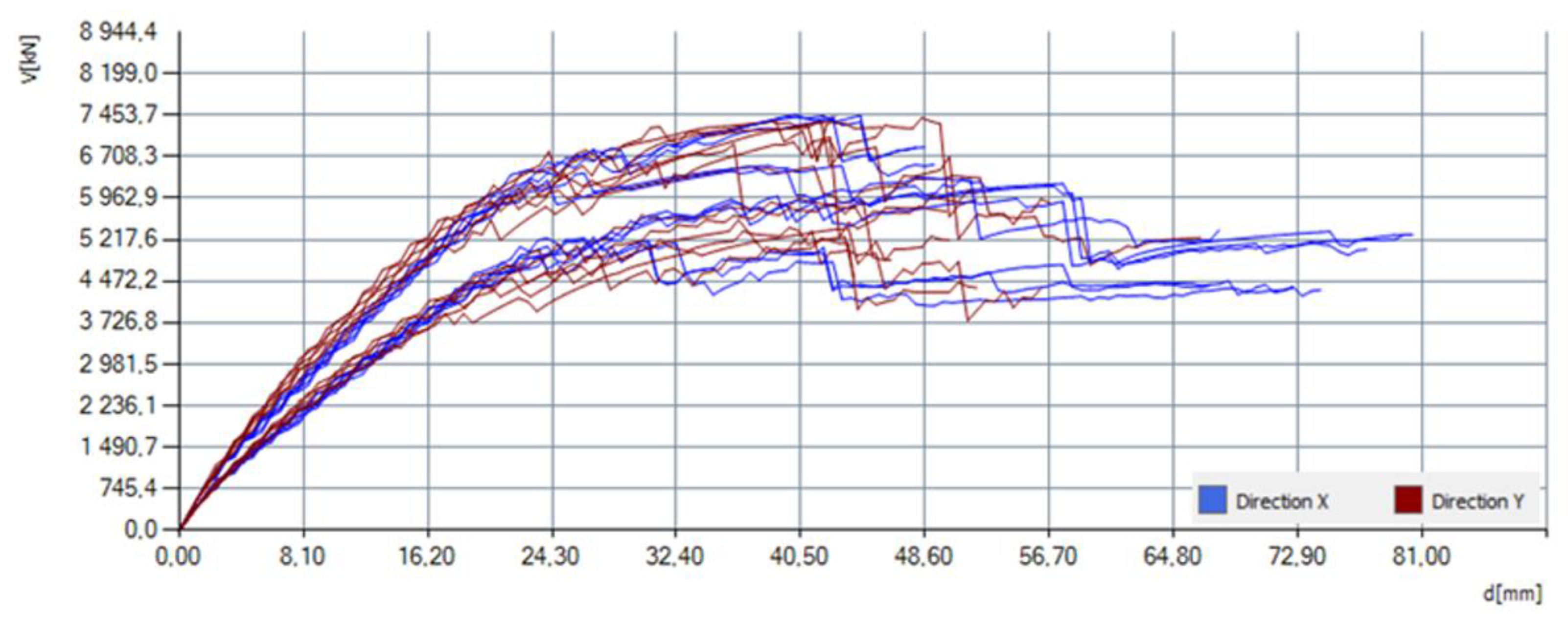
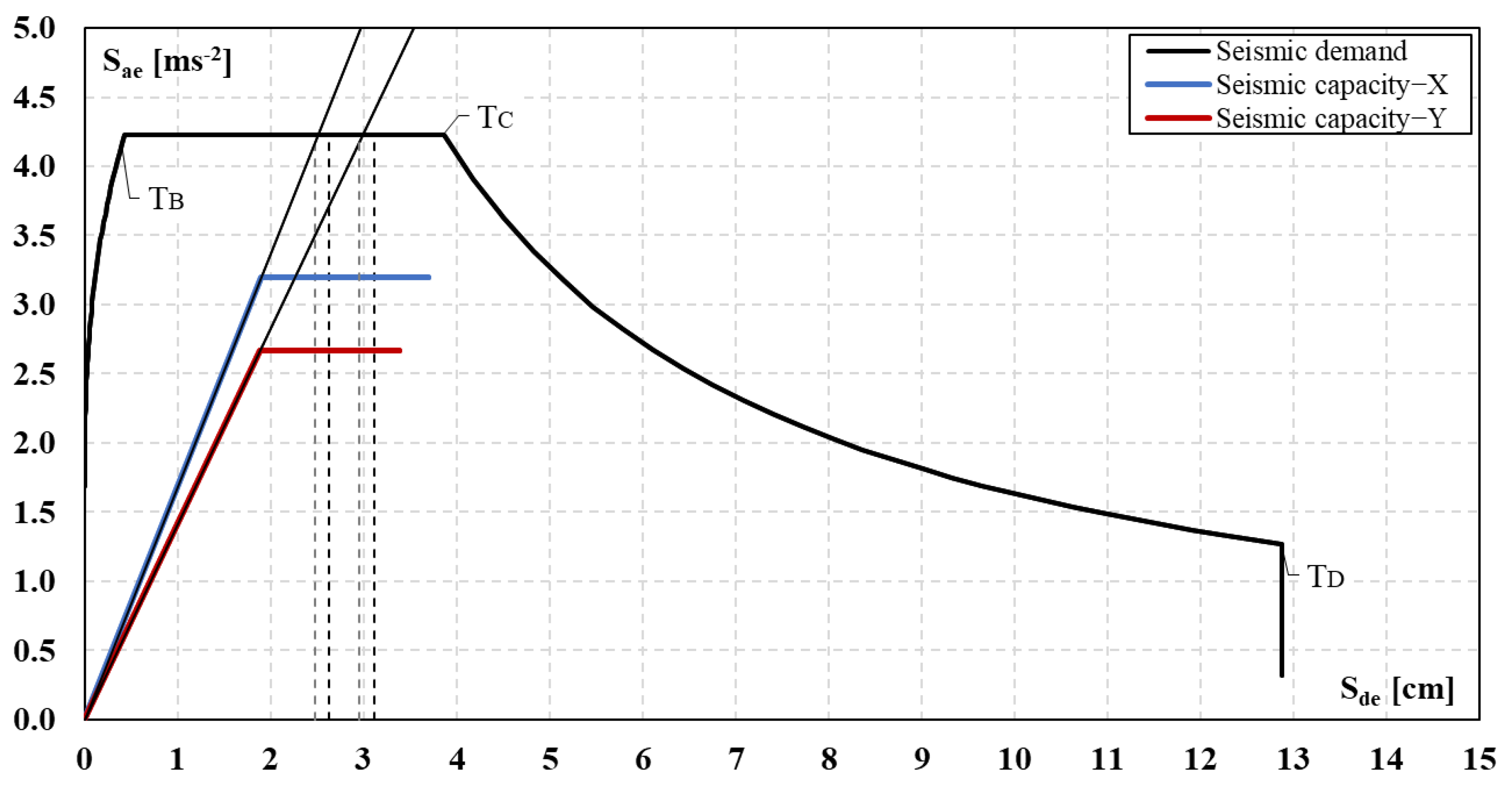
The structural capacity is described by pushover curves, whereas the structure is a multi-degrees-of-freedom (MDoF) system. The curve displays the correlation between the base shear and control displacement. The seismic demand is given in terms of the elastic response spectrum for a single-degree-of-freedom (SDoF) system. To compare the seismic capacity and demand, both must be in the same format. The pushover curve is firstly bilinearized. The bilinearization is performed by adapting the initial stiffness so that it equals a ratio of 70% of the maximum base shear and the corresponding displacement. The base shear is calculated based on the principle of equal fracture energies. The curve is then transformed from a multi-degrees-of-freedom (MDOF) to an equivalent single-degree-of-freedom (SDOF) system by means of Γ. The curve is finally converted into ADRS format, by dividing the base shear value F* by the equivalent mass of the SDOF m*. The calculation of target displacement differs for the structures with short periods (T* < TC) and for the structures with medium or long periods (T* > TC). The described method is known as the N2 method [35], and it is described in detail in Eurocode 1998-1 [36]. Except for pushover curves, 3Muri software also presents the results using risk index α, which is the ratio of capacity and demand in terms of acceleration. If the risk index for a certain analysis equals α ≥ 1.0, the seismic capacity is equal to or higher than the demand.
Elastic response spectra have been calculated for acceleration values, referencing three different return periods—475, 225, and 95 years—and amplified for the soil type C (Table 4). The return periods of 475 and 225 years refer to the “Significant damage” limit state, while the return period of 95 years refers to the “Damage limitation” limit state. Soil type C (deep deposits of compacted or medium-compacted sand, gravel, or hard clay with a thickness of several tens to hundreds of meters) is assumed based on the available data.
Geometric characteristics were derived from original plans and via visual inspection. To determine the material properties (Table 5.), in situ tests were carried out. The shear modulus is taken as a percentage of the elastic modulus. The specific weight is assumed according to the type of masonry. The compressive strength of the masonry was obtained using formula (3.1) from EN1996, and available data on the strength of the bricks and mortar of the structure, which were tested earlier. The roof structure was considered a non-structural element in the model, since it does not contribute significantly to the global resistance of the structure; however, its mass was taken into account in the calculation of the seismic force [37,38]. The base restraints have been set as fixed.
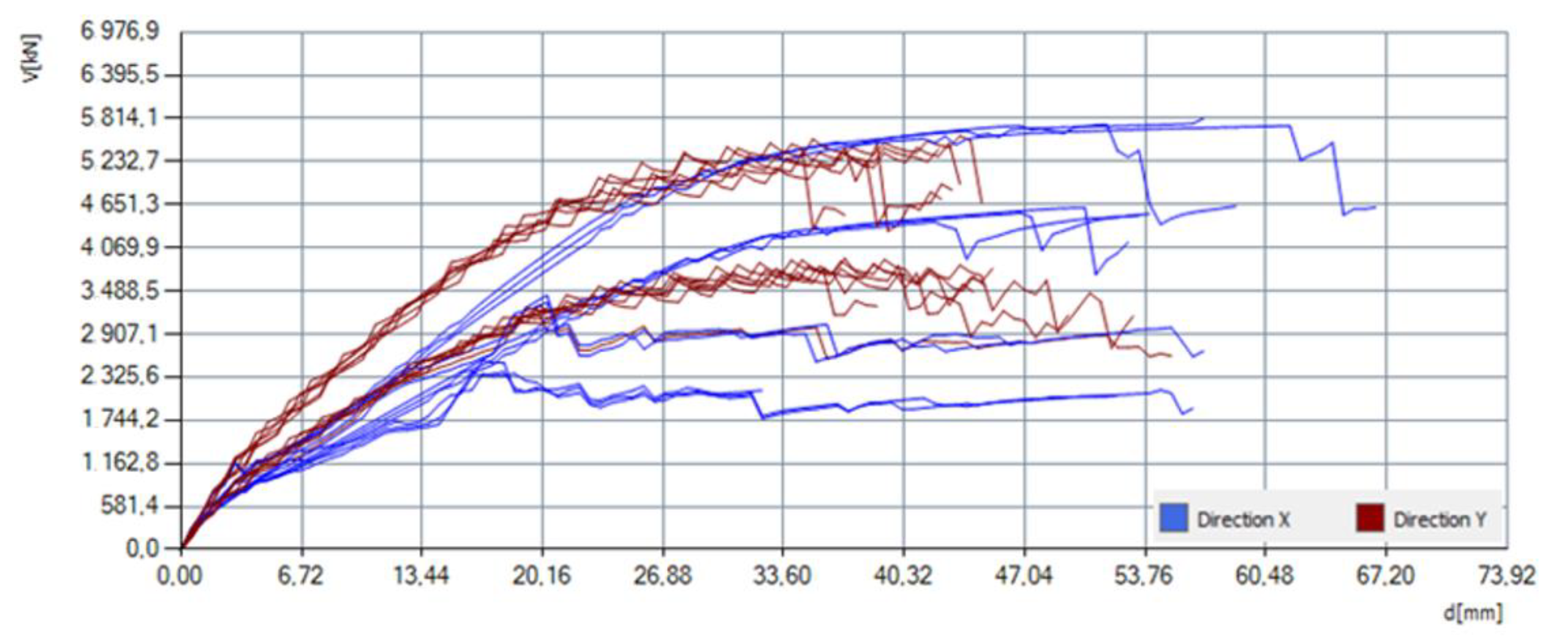
The pushover curves are shown in Figure 15. It is noted that the pushover curves vary within the same direction. The asymmetry of the building (both in plan and height) causes a higher shear capacity for the −X (negative) orientation versus the X (positive) orientation. Additionally, it is noted a higher shear capacity is accomplished for the uniform load distribution, in both the X and Y direction.
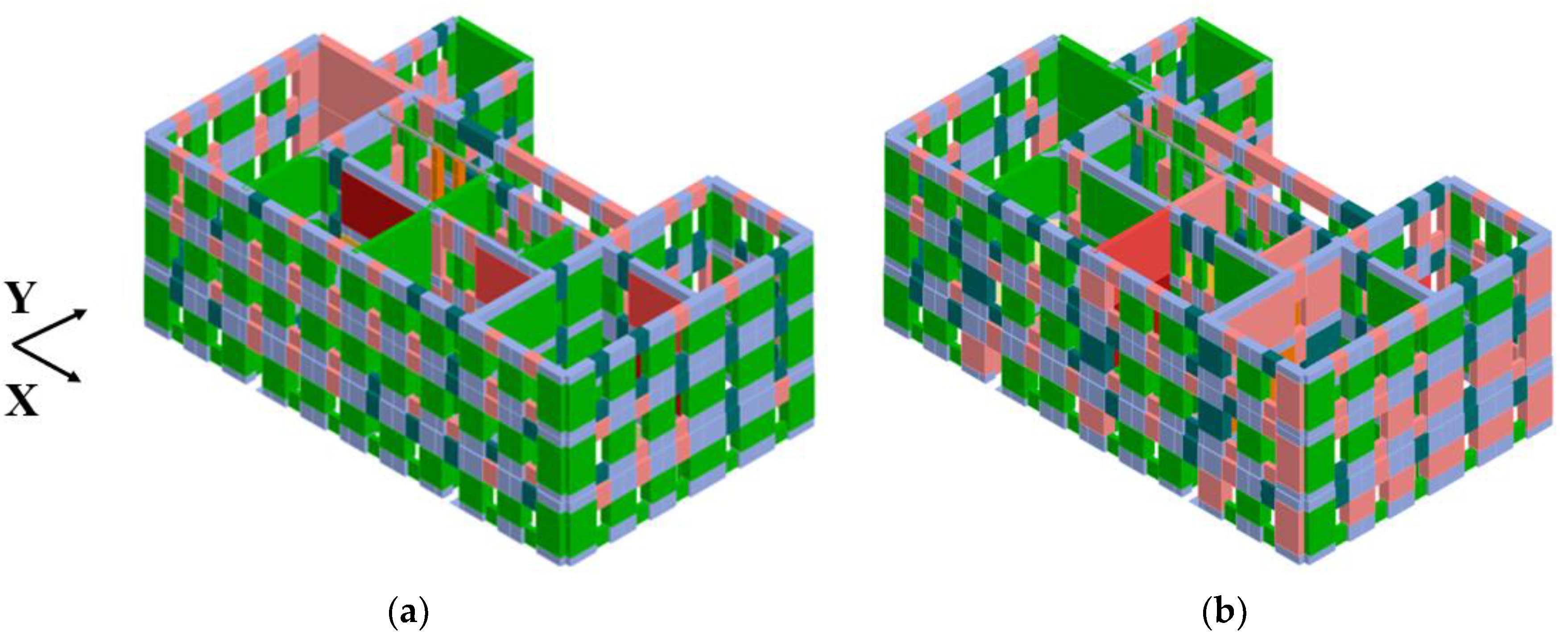
A visualization of the damage from the critical analyses is displayed in Figure 16. The images highlight the critical parts of the structure, which correspond to the actual damage scenarios (damaged spandrels and load-bearing walls in the longitudinal and transversal direction of the central part). Figure 17. displays the capacity curves in the X and Y direction, which are derived from the pushover curves with the lowest risk indices. The radial lines defined by the slope of the first part of the capacity curve represent the elastic structural period T*. The intersecting point of the period and the seismic demand is the elastic displacement of the SDoF. It is visible that the seismic capacity is equal in both directions. Still, the seismic demand is lower for the Y direction than the X direction. The latter justifies the higher risk indices in the Y direction, which are shown in Table 6. Accordingly, the structure does not satisfy the seismic requirements.
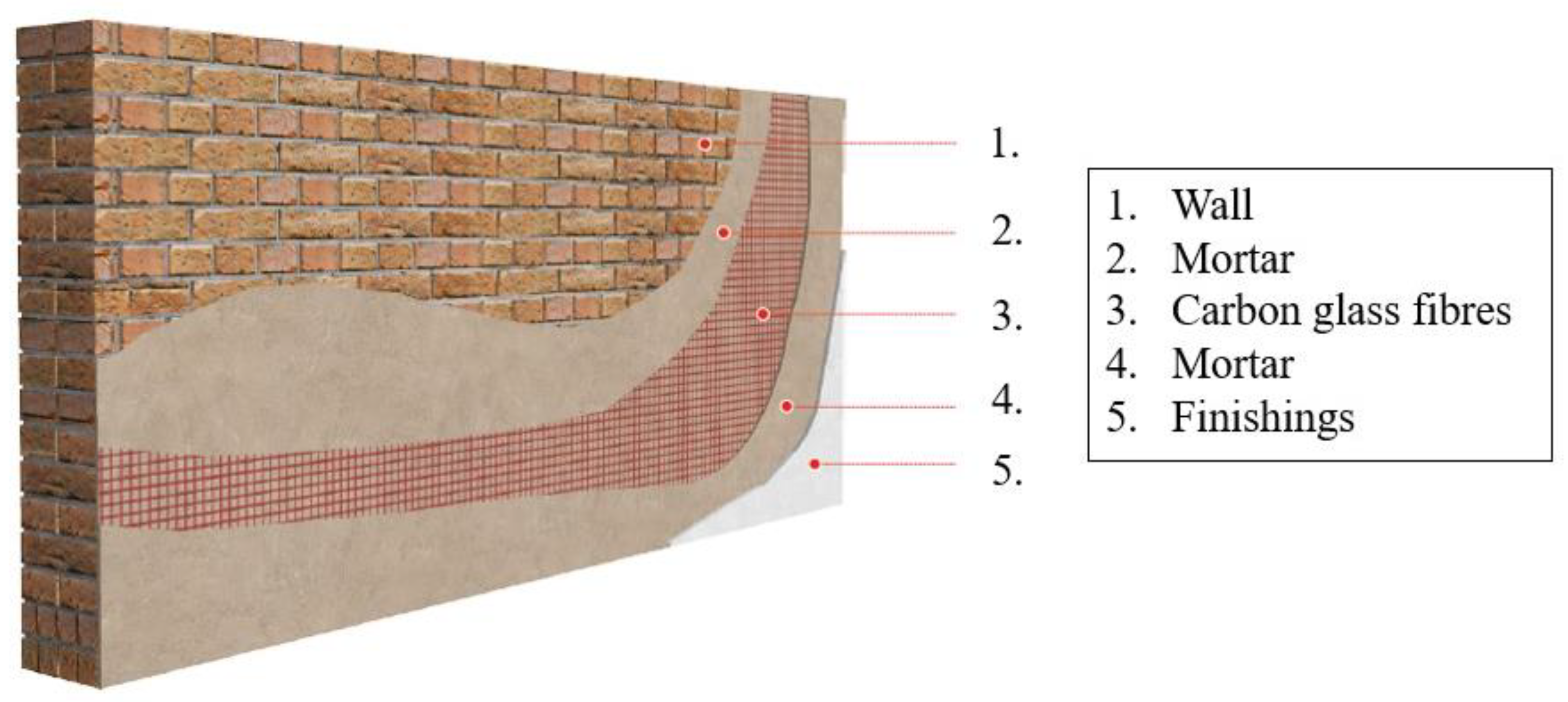
The common method of strengthening in Croatia is concrete jacketing (shotcrete). It has an immense impact on the global behavior of the structure, as it affects the structural stiffness significantly. Since this technique is quite invasive, in agreement with the conservators, it was concluded that the optimal solution [39,40] is strengthening by applying an FRCM (fabric-reinforced cementitious matrix) system [41], as seen in Figure 18. For the composite, carbon fibers were used, since they are frequently used in practice in Croatia due to their material characteristics and cost efficiency. The material is characterized by low weight, high tensile strength, and corrosion and fire resistance. However, compared to shotcrete, it is not as affordable, and it requires highly skilled craftsmen. Nevertheless, since the criterion of preserving the cultural identity of the structure is a priority, and also defined by the law, strengthening using the FRCM system is a preferable solution due to its non-invasiveness. Additionally, from the environmental point of view, FRCM is a more favorable solution compared to shotcrete [42]. It causes far fewer emissions of carbon dioxide, which contributes to the global trend of reducing carbon costs [43]. The composite’s characteristics have been provided by the manufacturer and are displayed in Table 7. Additionally, the existing wooden floors were coupled by introducing a 6 cm thick concrete layer. By adding the concrete layer, the in-plane stiffness of the floor structure increases, which makes the floor structure act as a rigid diaphragm [29]. This causes the distribution of internal forces proportionately to the stiffness of each element, and in case of potential future earthquake events, it ensures the translation of the floor structure without in-plane deformation.
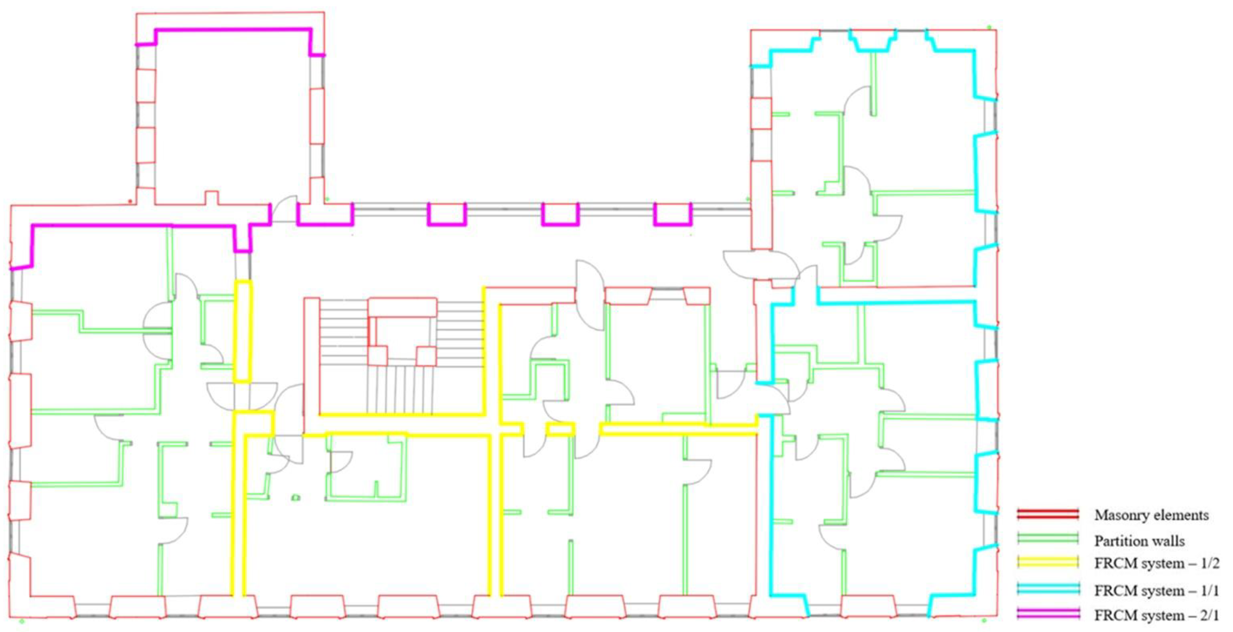
The required number of layers was calculated according to the values of internal forces. The resistance of the element was calculated, including the shear and bending failure. Shear failure includes both diagonal and sliding failure, while the bending failure is characterized by crushing in the compression area. The minimum value of the three is considered the resistance of the element. If the internal forces are higher than the resistance, the FRCM composite has been applied to the wall. The contribution of the FRCM system to the resistance of the wall layer was calculated. The number of layers is increased until a resistance greater than the internal forces is achieved. The FRCM composite was applied to the walls in the software, which caused the redistribution of the internal forces. Hence, the calculation of the strengthening is an iterative procedure. The proposed solution is displayed in Figure 19 and Figure 20. The walls on which the FRCM system is applied are marked according to the legend, and denoted l/n. l represents the number of layers applied per side of the wall, while n indicates if the FRCM system is applied to a single side of the wall (n = 1) [45,46] or on both sides (n = 2). Although the system is placed asymmetrically regarding the floor plan, the solution does not cause additional torsion, as the fibers have a low individual weight, and 0.5 cm of the cementitious matrix is applied per layer of the fibers. The system exclusively affects the in-plane capacity.
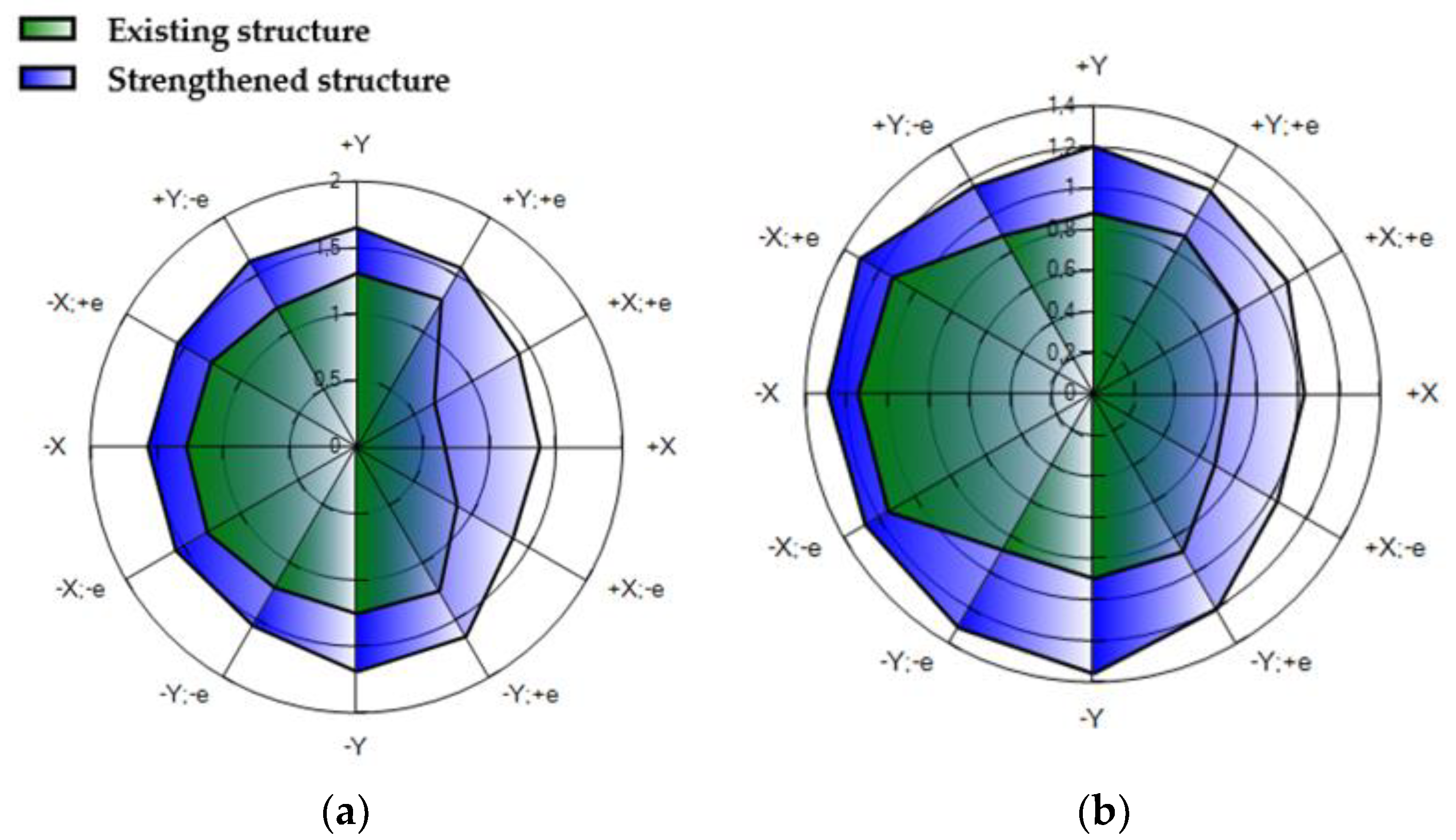
The results are shown in terms of risk indices, pushover curves and capacity curves (Table 8, Figure 21 and Figure 22). In total, 24 analyses were performed. The base shear value varies depending on the pushover analysis (load distribution, eccentricity load direction, and orientation). The discrepancies are high due to the plan and height irregularities. The aim was to satisfy 24 analyses, so the increase in the capacity also varies. The average increase for the X direction is 23–53%, while for the Y direction, it is 33–40%. The suggested solution caused the increase in seismic capacity to satisfy the level 3, α225 > 1.0. The significant increase in shear capacity in the X direction was noted; this was expected, since the FRCM system was mainly applied to the walls set in the longitudinal X direction. Both displacement capacity and ductility in the X direction increased. The displacement capacity increased in the Y direction, but the ductility remained the same.
The dynamic parameters are displayed in Table 9, before and after strengthening, for the corresponding SDoF systems.
Risk indices vary for each direction, which is displayed in Figure 23. It shows the comparison of risk indices for the limit state “Significant damage”, and the return period of 225 years for the existing and strengthened structures. It is visible that the capacity of the strengthened structure increased overall, regardless of the direction, orientation, and distribution of the forces.

5. Conclusions

In conclusion, this scientific article explored the assessment and retrofitting of cultural heritage through a case study of a residential building in Glina. The study aimed to preserve and enhance the architectural and historical significance of the building while ensuring its safety, functionality, and sustainability.
Through a comprehensive assessment, various aspects of the building were examined, including its structural integrity, material characteristics, and cultural value. This holistic approach allowed for a thorough understanding of the building’s characteristics and the challenges ahead. The retrofitting process involved implementing appropriate conservation and restoration strategies that respected the building’s original features and cultural context. Using 3Muri software and non-linear static seismic analysis, the assessment of the building’s behavior during an earthquake revealed that strengthening measures are necessary to enhance its seismic resistance. These interventions were carefully designed to strike a balance between preserving the building’s heritage value and meeting contemporary standards.
The case study in Glina serves as a valuable example of the successful integration of heritage preservation and sustainable retrofitting practices. In the process of renovating and reinforcing the seismic resistance of the protected heritage building, it is crucial to adopt minimally invasive methods that preserve the original architectural and historical values while ensuring safety and functionality. It also highlights the importance of interdisciplinary collaboration among architects, engineers, conservators, and other stakeholders in achieving these objectives. By adopting a multidimensional approach, it is possible to safeguard cultural heritage while ensuring the long-term viability and functionality of historic buildings. This study emphasizes the significance of preserving cultural heritage as an integral part of sustainable development. The retrofitting process not only enhances the longevity of historic structures, but also contributes to the revitalization of communities and the promotion of cultural identity. It serves as a model for future projects aiming to balance heritage preservation with the demands of modern society. In future work, it will be important to emphasize the importance of different types of unique retrofitting solutions for each cultural heritage building, as every building brings its own problems and challenges.
In conclusion, the assessment and retrofitting of cultural heritage, as demonstrated through the case study of a residential building in Glina, offers valuable insights and guidelines for similar projects. By embracing innovative conservation strategies, interdisciplinary collaboration, and a deep appreciation of heritage value, we can successfully preserve and revitalize our cultural treasures for future generations to cherish and enjoy.

Author Contributions

Conceptualization, K.O. and I.M.; Data curation, A.M.; Methodology, K.O. and L.L.; Software, K.O., A.M. and L.L.; Supervision, I.M.; Validation, L.L.; Writing—original draft, K.O.; Writing—review and editing, K.O., I.M. and A.M. All authors have read and agreed to the published version of the manuscript.

Funding

This research was funded by the Croatian Science Foundation, grant number UIP-2019–04-3749 (ARES project—assessment and rehabilitation of existing structures—development of contempo-rary methods for masonry and timber structures), project leader: Mislav Stepinac.

Data Availability Statement

Data can be shared on request.

Conflicts of Interest

The authors declare no conflict of interest.

References

  1. Government of the Republic of Croatia. Croatia December 2020 Earthquake Rapid Damage and Needs Assessment; The World Bank: Washington, DC, USA, 2021. [Google Scholar]
  2. Stepinac, M.; Lourenço, P.B.; Atalić, J.; Kišiček, T.; Uroš, M.; Baniček, M.; Novak, M.Š. Damage classification of residential buildings in historical downtown after the ML5.5 earthquake in Zagreb, Croatia in 2020. Int. J. Disaster Risk Reduct. 2021, 56, 102140. [Google Scholar] [CrossRef]
  3. Moretić, A.; Chieffo, N.; Stepinac, M.; Lourenço, P.B. Vulnerability Assessment of Historical Building Aggregates in Zagreb: Implementation of a Macroseismic Approach. Bull Earthq. Eng. 2022, 21, 2045–2065. [Google Scholar] [CrossRef]
  4. Grillanda, N.; Valente, M.; Milani, G.; Formigoni, F.; Chiozzi, A.; Tralli, A. Fast Seismic Vulnerability Evaluation of Historical Masonry Aggregates through Local Analyses: An Adaptive NURBS-based Limit Analysis Approach. In Proceedings of the 12th International Conference on Structural Analysis of Historical Constructions (SAHC), Barcelona, Spain, 16–18 September 2020; pp. 1–13. [Google Scholar]
  5. Valente, M. Seismic vulnerability assessment and earthquake response of slender historical masonry bell towers in South-East Lombardia. Eng. Fail. Anal. 2021, 129, 105656. [Google Scholar] [CrossRef]
  6. Ferretti, E.; Pascale, G. Some of the Latest Active Strengthening Techniques for Masonry Buildings: A Critical Analysis. Materials 2019, 12, 1151. [Google Scholar] [CrossRef] [Green Version]
  7. Holicky, M.; Sykora, M. Structural assessment of heritage buildings. WIT Trans. Built Environ. 2012, 123, 69–80. [Google Scholar]
  8. Atalić, J.; Šavor Novak, M.; Uroš, M. Seismic risk for Croatia: Overview of research activities and present assessments with guidelines for the future. Građevinar 2019, 71, 923–947. [Google Scholar]
  9. Department of Geophysics. Available online: http://www.pmf.unizg.hr/geof/en (accessed on 26 April 2023).
  10. Ožić, K.; Skejić, D.; Lukačević, I.; Stepinac, M. Value of Information Analysis for the Post-Earthquake Assessment of Existing Masonry Structures—Case Studies. Buildings 2023, 13, 144. [Google Scholar] [CrossRef]
  11. Der Kiureghian, A.; Ditlevsen, O. Aleatory or epistemic? Does it matter? Struct. Saf. 2009, 31, 105–112. [Google Scholar] [CrossRef]
  12. Sýkora, M.; Diamantidis, D.; Holický, M.; Marková, J.; Rózsás, Á. Assessment of compressive strength of historic masonry using non-destructive and destructive techniques. Constr. Build. Mater. 2018, 193, 196–210. [Google Scholar] [CrossRef]
  13. ARES PROJECT Assessment and Rehabilitation of Existing Structures—Development of Contemporary Methods for Masonry and Timber Structures. Available online: https://www.grad.hr/ares/ (accessed on 15 December 2021).
  14. Stepinac, M.; Skokandić, D.; Ožić, K.; Zidar, M.; Vajdić, M. Condition Assessment and Seismic Upgrading Strategy of RC Structures—A Case Study of a Public Institution in Croatia. Buildings 2022, 12, 1489. [Google Scholar] [CrossRef]
  15. Funari, M.F.; Hajjat, A.E.; Masciotta, M.G.; Oliveira, D.V.; Lourenço, P.B. A Parametric Scan-to-FEM Framework for the Digital Twin Generation of Historic Masonry Structures. Sustainability 2021, 13, 11088. [Google Scholar] [CrossRef]
  16. Valente, M. Seismic behavior and damage assessment of two historical fortified masonry palaces with corner towers. Eng. Fail. Anal. 2021, 134, 106003. [Google Scholar] [CrossRef]
  17. D’altri, A.M.; Sarhosis, V.; Milani, G.; Rots, J.; Cattari, S.; Lagomarsino, S.; Sacco, E.; Tralli, A.; Castellazzi, G.; de Miranda, S. Modeling Strategies for the Computational Analysis of Unreinforced Masonry Structures: Review and Classification. Arch. Comput. Methods Eng. 2019, 27, 1153–1185. [Google Scholar] [CrossRef]
  18. D’Altri, A.M.; de Miranda, S.; Castellazzi, G.; Sarhosis, V. A 3D detailed micro-model for the in-plane and out-of-plane numerical analysis of masonry panels. Comput. Struct. 2018, 206, 18–30. [Google Scholar] [CrossRef] [Green Version]
  19. Lagomarsino, S.; Penna, A.; Galasco, A.; Cattari, S. TREMURI program: An equivalent frame model for the nonlinear seismic analysis of masonry buildings. Eng. Struct. 2013, 56, 1787–1799. [Google Scholar] [CrossRef]
  20. Fraternali, F. A thrust network approach to the equilibrium problem of unreinforced masonry vaults via polyhedral stress functions. Mech. Res. Commun. 2010, 37, 198–204. [Google Scholar] [CrossRef]
  21. Bilgin, H.; Shkodrani, N.; Hysenlliu, M.; Ozmen, H.B.; Isik, E.; Harirchian, E. Damage and performance evaluation of masonry buildings constructed in 1970s during the 2019 Albania earthquakes. Eng. Fail. Anal. 2021, 131, 105824. [Google Scholar] [CrossRef]
  22. Uroš, M.; Šavor Novak, M.; Atalić, J.; Sigmund, Z.; Baniček, M.; Demšić, M.; Hak, S. Post-earthquake damage assessment of buildings—Procedure for conducting building inspections. J. Croat. Assoc. Civ. Eng. 2021, 72, 1089–1115. [Google Scholar]
  23. Kišiček, T.; Stepinac, M.; Renić, T.; Hafner, I.; Lulić, L. Strengthening of masonry walls with FRP or TRM. J. Croat. Assoc. Civ. Eng. 2020, 72, 937–953. [Google Scholar]
  24. Stepinac, M.; Gašparović, M. A Review of Emerging Technologies for an Assessment of Safety and Seismic Vulnerability and Damage Detection of Existing Masonry Structures. Appl. Sci. 2020, 10, 5060. [Google Scholar] [CrossRef]
  25. ASTM C1197-14a; Standard Test Method for in situ Measurement of Masonry Deformability Properties Using the Flatjack Method. ASTM International: West Conshohocken, PA, USA, 2014.
  26. RILEM Technical Committee. RILEM TC 177-MDT: Masonry Durability and on-Site Testing Recommendation MDT. D. 4: In-Situ Stress Tests Based on the Flat jack. Mater Struct. 2004, 37, 491. Available online: http://www.springerlink.com/index/10.1007/BF02481588 (accessed on 15 March 2023).
  27. Lulić, L.; Stepinac, M.; Bartolac, M.; Lourenço, P.B. Review of the Flat-Jack Method and Lessons from Extensive Post-Earthquake Research Campaign in Croatia. Constr. Build. Mater. 2023, 384. Available online: https://linkinghub.elsevier.com/retrieve/pii/S0950061823011200 (accessed on 5 June 2023). [CrossRef]
  28. Stepinac, M.; Lulić, L.; Damjanović, D.; Duvnjak, I.; Bartolac, M.; Lourenço, P.B. Experimental Evaluation of Unreinforced Brick Masonry Mechanical Properties by the Flat-Jack Method–An Extensive Campaign in Croatia. Int. J. Arch. Heritage 2023, 1–18. [Google Scholar] [CrossRef]
  29. Costamagna, E.; Quintero, M.S.; Bianchini, N.; Mendes, N.; Lourenço, P.B.; Su, S.; Paik, Y.M.; Min, A. Advanced non-destructive techniques for the diagnosis of historic buildings: The Loka-Hteik-Pan temple in Bagan. J. Cult. Herit. 2019, 43, 108–117. [Google Scholar] [CrossRef]
  30. Ortega, J.; Stepinac, M.; Lulić, L.; Nunez Garcia, M.; Saloustros, S.; Aranha, C. Correlation between Sonic Pulse Velocity and Flat-Jack Tests for the Estimation of the Elastic Properties of Unreinforced Brick Masonry: Case Studies from Croatia (Under Review in Case Studies in Construction Materials, Netherlands); 2023.
  31. Borri, A.; Corradi, M.; Castori, G.; De Maria, A. A method for the analysis and classification of historic masonry. Bull. Earthq. Eng. 2015, 13, 2647–2665. [Google Scholar] [CrossRef]
  32. Law on the Reconstruction of Earthquake-Damaged Buildings in the City of Zagreb, Krapina-Zagorje County, Zagreb County, Sisak-Moslavina County and Karlovac County (NN 21/23). Available online: https://www.zakon.hr/z/2656/Zakon-o-obnovi-zgrada-oštećenih-potresom-na-području-Grada-Zagreba%2C-Krapinsko-zagorske-županije%2C-Zagrebačke-županije%2C-Sisačko-moslavačke-županije-i-Karlovačke-županije (accessed on 27 April 2023).
  33. Milani, G.; Shehu, R.; Valente, M. Seismic Upgrading of a Masonry Church with FRP Composites. Mater. Sci. Forum 2016, 866, 119–123. [Google Scholar] [CrossRef]
  34. S.T.A. DATA, 3Muri Program 12.5.0.2. Available online: http://www.stadata.com/ (accessed on 14 December 2021).
  35. Fajfar, P.; Gašperšič, P. The N2 method for the seismic damage analysis of RC buildings. Earthq. Eng. Struct. Dyn. 1996, 25, 31–46. [Google Scholar] [CrossRef]
  36. EN 1998-1:2004; Eurocode 8: Design of Structures for Earthquake Resistance—Part 1: General Rules, Seismic Actions and Rules for Buildings. European Committee for Standardization: Brussels, Belgium, 2004.
  37. Gomes, M.I.; Lopes, M.; de Brito, J. Seismic resistance of earth construction in Portugal. Eng. Struct. 2010, 33, 932–941. [Google Scholar] [CrossRef]
  38. Lulić, L.; Ožić, K.; Kišiček, T.; Hafner, I.; Stepinac, M. Post-Earthquake Damage Assessment—Case Study of the Educational Building after the Zagreb Earthquake. Sustainability 2021, 13, 6353. [Google Scholar] [CrossRef]
  39. Law on the Protection and Preservation of Cultural Heritage. Available online: https://www.zakon.hr/z/340/Zakon-o-zaštiti-i-očuvanju-kulturnih-dobara (accessed on 16 February 2022).
  40. Yavartanoo, F.; Kang, T.H.-K. Retrofitting of unreinforced masonry structures and considerations for heritage-sensitive constructions. J. Build. Eng. 2022, 49, 103993. [Google Scholar] [CrossRef]
  41. Abbass, A.; Lourenço, P.B.; Oliveira, D.V. The use of natural fibers in repairing and strengthening of cultural heritage buildings. Mater. Today: Proc. 2020, 31, S321–S328. [Google Scholar] [CrossRef]
  42. Moretić, A.; Stepinac, M.; Lourenço, P.B. Seismic upgrading of cultural heritage—A case study using an educational building in Croatia from the historicism style. Case Stud. Constr. Mater. 2022, 17, e01183. [Google Scholar] [CrossRef]
  43. Low-Carbon Development Strategy of the Republic of Croatia until 2030 with a view to 2050. The Republic of Croatia, Ministry of Economy and Sustainable Development. Available online: https://mingor.gov.hr/o-ministarstvu-1065/djelokrug/uprava-za-klimatske-aktivnosti-1879/strategije-planovi-i-programi-1915/strategija-niskougljicnog-razvoja-hrvatske/1930 (accessed on 27 April 2023).
  44. BAUMIT. Available online: https://baumit.hr/ (accessed on 27 April 2023).
  45. Del Zoppo, M.; Di Ludovico, M.; Prota, A. Analysis of FRCM and CRM parameters for the in-plane shear strengthening of different URM types. Compos. Part B Eng. 2019, 171, 20–33. [Google Scholar] [CrossRef]
  46. Babaeidarabad, S.; De Caso, F.; Nanni, A. URM Walls Strengthened with Fabric-Reinforced Cementitious Matrix Composite Subjected to Diagonal Compression. J. Compos. Constr. 2014, 18, 242. [Google Scholar] [CrossRef]
Figure 2. South-west facade of case study building.
Buildings 13 01798 g002
Figure 3. North-east facade of case study building.
Buildings 13 01798 g003
Figure 4. Ground storey floor plan.
Buildings 13 01798 g004
Figure 5. First and second storey floor plan.
Buildings 13 01798 g005
Figure 6. Transversal building sections A and B.
Buildings 13 01798 g006
Figure 7. Damage patterns (red marks): (a) ground floor, (b) first floor, and (c) second floor.
Buildings 13 01798 g007
Figure 8. Cracks on the load-bearing walls on the first floor.
Buildings 13 01798 g008
Figure 9. Cracks at the junctions of load-bearing walls.
Buildings 13 01798 g009
Figure 10. Damage to the facade.
Buildings 13 01798 g010
Figure 11. Collapsed chimney and damaged roof covering.
Buildings 13 01798 g011
Figure 12. Flat-jack method: (a) single flat-jack test, (b) double flat-jack test, and (c) shear test.
Buildings 13 01798 g012
Figure 13. Measured displacement during double flat-jack test.
Buildings 13 01798 g013
Figure 14. Change in shear stress during the test (blue line).
Buildings 13 01798 g014
Figure 15. Pushover curves of the existing structure in the current condition.
Buildings 13 01798 g015
Figure 16. Damage visualization for the most critical analysis in the (a) X direction and (b) Y direction.
Buildings 13 01798 g016
Figure 17. Seismic demand and capacity of the existing structure.
Buildings 13 01798 g017
Figure 18. Application of the FRCM system.
Buildings 13 01798 g018
Figure 19. Strengthened structure of the ground floor.
Buildings 13 01798 g019
Figure 20. Strengthened structure of the first and second floor.
Buildings 13 01798 g020
Figure 21. Pushover curves of the strengthened structure.
Buildings 13 01798 g021
Figure 22. Seismic demand and capacity of the strengthened structure.
Buildings 13 01798 g022
Figure 23. Comparison of the risk indices of the models of the existing structure and the structure strengthened using FRCM: (a) uniform distribution; (b) distribution proportionate to the static forces.
Buildings 13 01798 g023
Table 1. Single flat-jack test results.
FloorMarkt
(cm)
h
(cm)
KmKap
(bar)
σ0
(N/mm2)
Ground floorFJ-160630.7590.9096.40.44
First floorFJ-260650.7610.9203.10.21
Table 2. Double flat-jack test results.
FloorMarkE
(N/mm2)
Ground floorFJ-1831
First floorFJ-2648
Table 3. Shear test results.
FloorMarkμfvo
(N/mm2)
Ground floorFJ-10.360.15
First floorFJ-20.510.22
Table 4. PGA values.
Limit StateReturn Period (Year)Peak Ground Acceleration
Significant damage4750.15 g
Significant damage2250.11 g
Damage limitation950.07 g
Table 5. Masonry material characteristics.
Material CharacteristicsValue
Modulus of elasticity (N/mm2)740
Shear modulus (N/mm2)300
Specific weight (kN/m3)18
Mean compressive strength (N/mm2)2.8
Shear strength (N/mm2)0.18
Characteristic compressive strength (N/mm2) 2.2
Table 6. Risk indices of the existing structure in the current condition.
Limit StateReturn Period (Years)α (X Direction)α (Y Direction)
Significant damage4750.4240.565
Significant damage2250.6060.807
Damage limitation950.8190.891
Table 7. FRCM system characteristics [44].
FRCM SystemValue
Fiber thickness tf (mm)0.045
Modulus of elasticity E (N/mm2)194,000
Conventional strain limit (%)0.91
Table 8. Risk indices of the strengthened structure.
Limit StateReturn Period (Years)α (X Direction)α (Y Direction)
Significant damage4751.0990.781
Significant damage2251.451 1.163
Damage limitation951.563 1.309
Table 9. Structural periods.
DirectionExisting StructureStrengthened Structure
X0.690.48
Y0.58 0.52
Disclaimer/Publisher’s Note: The statements, opinions and data contained in all publications are solely those of the individual author(s) and contributor(s) and not of MDPI and/or the editor(s). MDPI and/or the editor(s) disclaim responsibility for any injury to people or property resulting from any ideas, methods, instructions or products referred to in the content.