Article

Enhancing Ground Improvement of Dredging Landfill in South Korea’s Western Coastal Region: Insights into Dynamic Compaction Characteristics

Department of Agricultural and Rural Engineering, Chungbuk National University, Cheongju 26844, Republic of Korea
Buildings 2023, 13(7), 1830; https://doi.org/10.3390/buildings13071830
Submission received: 15 June 2023 / Revised: 14 July 2023 / Accepted: 18 July 2023 / Published: 19 July 2023
(This article belongs to the Section Building Energy, Physics, Environment, and Systems)

Abstract

:
In this study, a dynamic compaction soil box test is performed to analyze the effect of changes in energy according to the pounder tamping number of dynamic compactions on ground improvement. As reproducing the test on the in situ ground is challenging, a 3.0 m × 2.4 m × 1.0 m soil box is used. The number of pounder tamping repetitions of the dynamic compaction is tested in up to six steps, five times at each tamping point. The change in excess pore water pressure appears to begin to converge at step three (Nd = 15) of pounder tamping. The change in pore water pressure with respect to the number of tamping using the finite element analysis program AFIMEX GT-2D is found to have an effect at up to 4.0 m vertically and 3.0 m horizontally, similar to the results of the soil box test. The static cone penetration resistance at each pounder tamping stage increases by 1.3, 1.7, and 1.1 times at step two (Nd = 10), step three (Nd = 15), and step six (Nd = 30) of tamping, respectively. The depth of improvement coefficient (α) ranges from 0.26 to 0.52, with an average of 0.39. The improvement effect of the in situ improved ground can be inferred in advance from the correlation between the number of pounder tamping repetitions, ΔN, and the internal friction angle. Once the ground improvement range is determined, it can be used to determine the in situ dynamic compaction energy (weight of pounder, tamping of height) using the given improvement depth coefficient (α).

1. Introduction

In coastal reclamation, the ground artificially reclaimed by dredged soil exhibits a heterogeneous stratum distribution [1]. Silty sand, which is abundant along the western coast of South Korea, is used extensively in coastal reclamation projects. To improve the mechanical properties of silty sand, a compaction method is used as a ground improvement technology; in this method, a pounder is repeatedly dropped from a specific height onto predetermined points [2].
The practice of using pounders for ground improvement can be traced back to ancient times, with the earliest recorded instance found in a German site [3]. Dynamic compaction, achieved through pounder tamping, minimizes subsidence by enhancing the bearing capacity of the ground at various depths. This concept has been applied in various contexts, including the structural strengthening of buildings and mitigating the risk of soil liquefaction in highways, airports, and seismically active areas [4]. Notably, dynamic compaction was recently used in a large-scale urban construction project initiated in the desert of Kuwait, where it facilitated the densification of sand fills through hydraulic filling [5,6] and the installation of pile foundations in loose granular soil sites involving deep sediments [7]. Various studies have investigated various aspects such as estimating the depth of ground improvement using dynamic compaction in sandy ground through two-dimensional finite element analysis [8], examining the effect of the change in pounder diameter used for dynamic compaction [9], and identifying and improving landfill effects [10].
In South Korea, the widespread use of dynamic compaction began in the late 1980s, thus leading to extensive studies. For example, Lee et al. (1993) investigated the various cases of ground improvement [11]. Nam (2018) evaluated the ground improvement depth of dynamic compaction method for waste landfill ground [12]. Moreover, Lee et al. (2005) applied dynamic compaction for site improvement and evaluated the depth of improvement [13]. Wrryu et al. (2010) presented a design case for the dynamic compaction method in direct foundation installation in unstable ground [14]. Lee et al. (2010) studied the depth of dynamic compaction improvement and the prediction of vibration effects using numerical analysis [15].
Dynamic compaction, which involves the repeated tamping of soil with a pounder, improves the soft ground beneath the tamping point. This method generates excess pore water pressure (EPP) and volume waves, including transverse, longitudinal, and surface waves, as illustrated in Figure 1 [16]. In particular, the generation and dissipation of excessive pore water pressure is related to soil consolidation [17].
Dynamic compaction takes longer for clayey soils compared with non-cohesive soils. Nevertheless, it remains one of the most cost-effective methods for compacting non-cohesive soils in terms of cost and time. This is because the radial cracks that form around the repeated tamping points drain excess pore water and cause immediate settlement [18]. Jiang et al. (2021) emphasized the importance of considering the effect of compaction energy in finite element analysis when comparing factors such as the arrangement of compaction equipment, compaction interval, and time interval in dynamic compaction construction [19]. Similarly, Zhang et al. (2021) reported that dynamic compaction is a cost-effective foundation treatment technology; in particular, the effect of dynamic compaction can be enhanced by improving the energy level even in low-moisture content soils [20]. These findings align with the increased dynamic compaction efficiency observed in the soil box test results, which are achieved by altering the dynamic compaction energy by changing the weight of pounder and height of tamping. This result emphasizes that the optimal energy level should be determined using parameters related to dynamic compaction.
As revealed by several studies, although the concept of dynamic compaction is simple, the effectiveness of ground improvement through high-energy tamping is evident. However, an intensive in situ testing program is required to thoroughly examine the effectiveness of ground improvement. However, most existing studies are based on case studies and numerical analysis. Additionally, research on the results of ground improvement in actual cases or similar tests is currently limited. Moreover, studies investigating the relationship between the excess pore water pressure and the number of pounder strikes are limited, and the scope and effect of ground improvement through this approach is rarely reported.
Therefore, in this study, a dynamic compaction test was conducted in a soil box filled with dredged soil reclaimed from the western coast of South Korea. The dynamic compaction test focused on analyzing changes in ground strength based on the number of pounder tamping repetitions and considering the range of depth coefficient (α) for ground improvement. This range enables the conversion of the optimal number of pounder tamping repetitions and dynamic compaction energy.

2. Materials and Methods

2.1. Characteristics of Soil
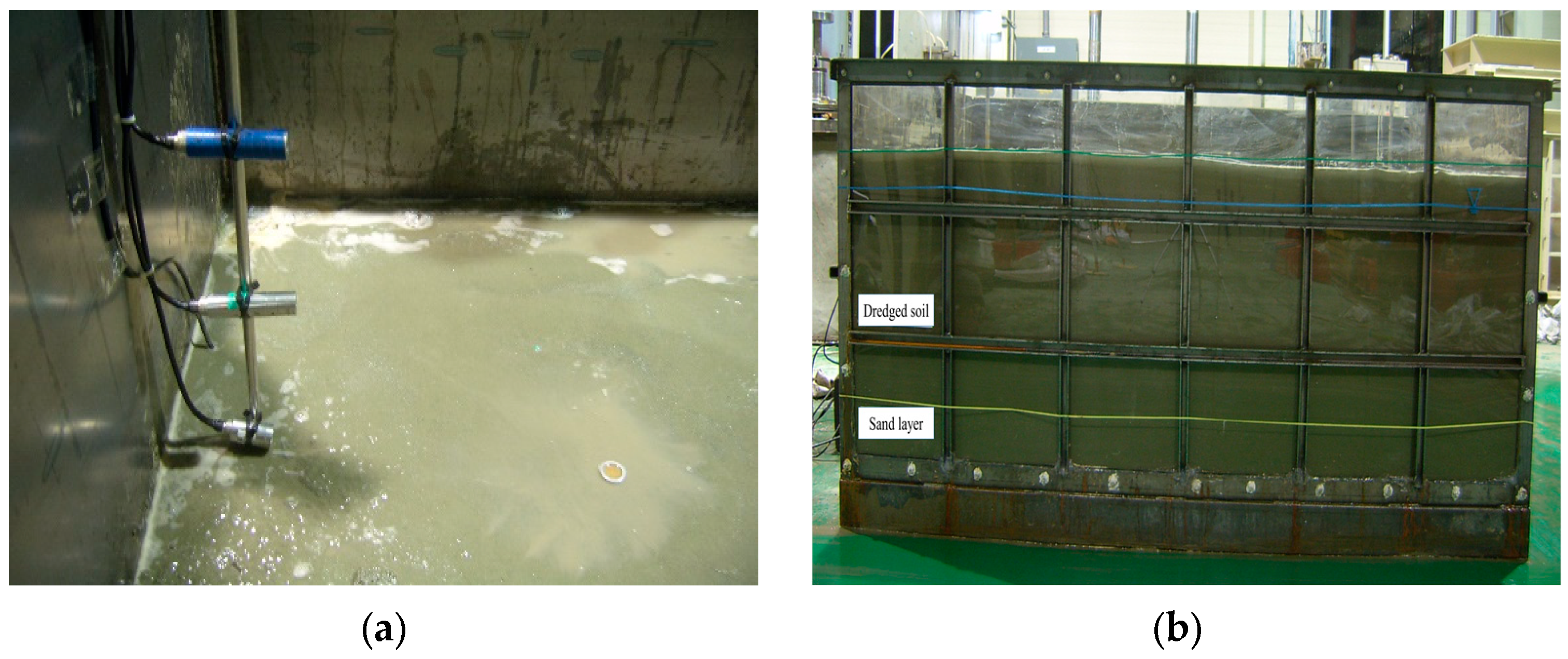
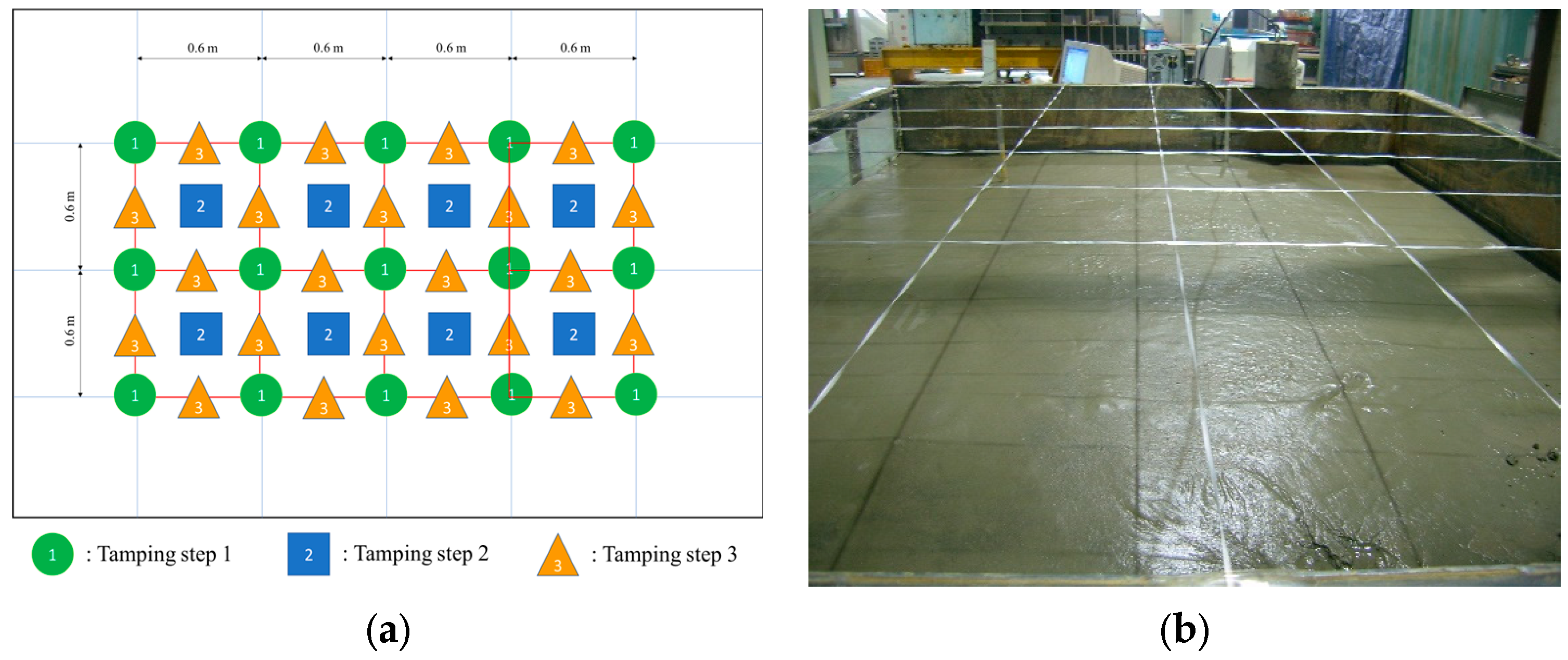
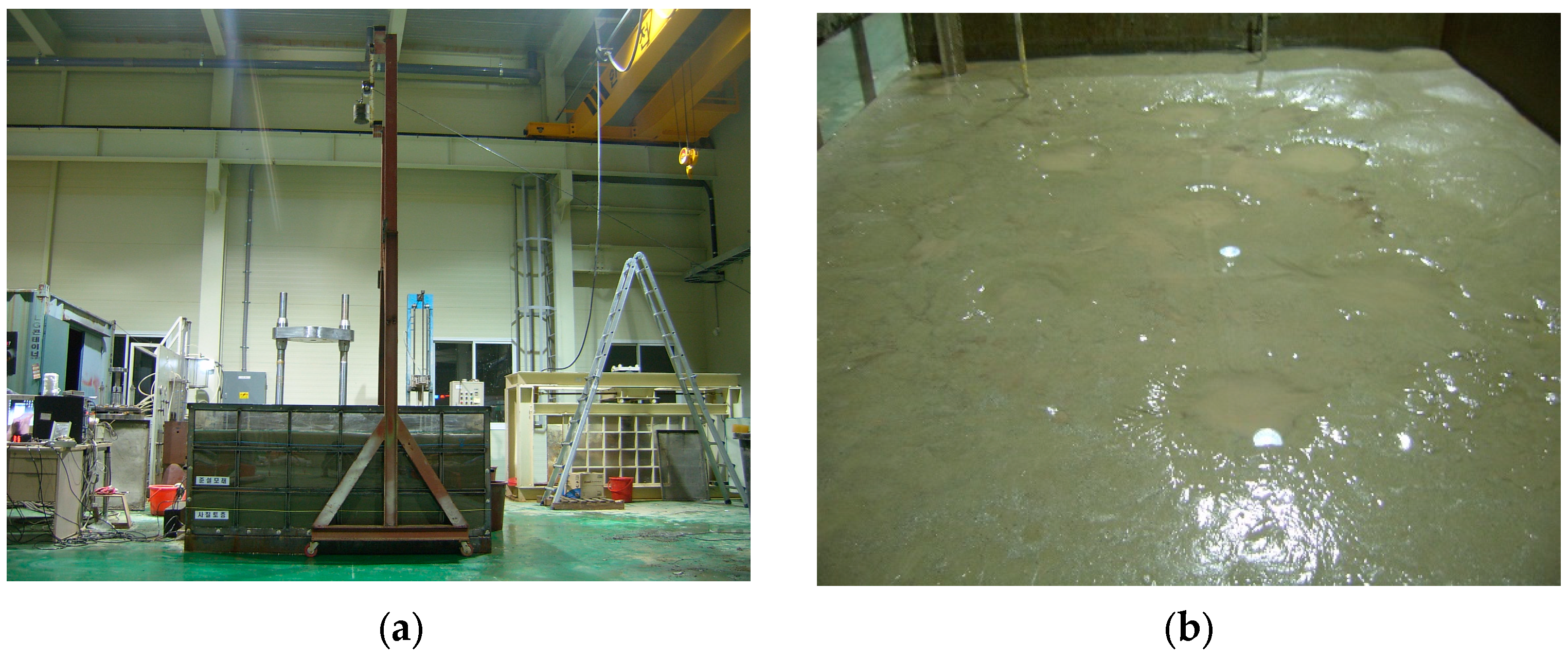
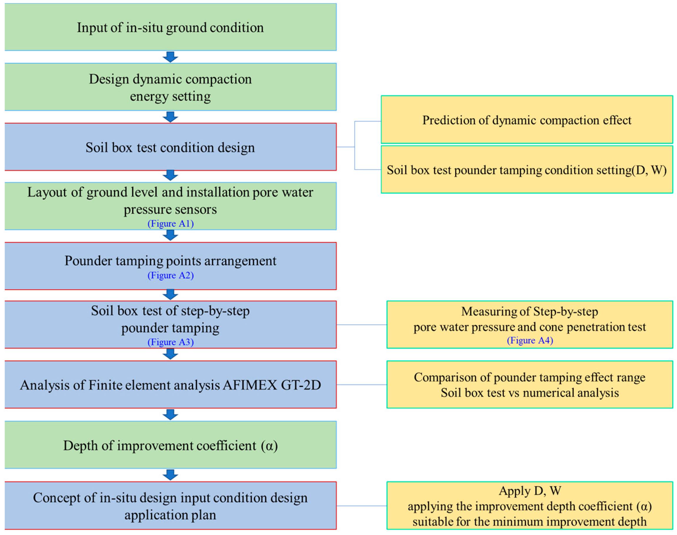
The soil used in the soil box was collected from Saemangeum reclaimed land located in Gimje-si, Jeollabuk-do. The soil sampling locations are shown in Figure 2. After construction of the embankment, this location was used as a landfill site using dredged sand. The physical characteristics of dredged soil are summarized in Table 1. Dredged soil is classified as SM according to the USCS classification system, with a sieve diameter of 0.074 mm, passing percent of 25.2%, natural water content of 25.2%, and consistency determined as non-plasticity (NP). The USCS suggests the standard size of soil particles to be 0.074 mm. The sieve used is designated as #200, and the passing percentage is a standard measure for classifying sand, silt, or clay.

2.2. Soil Box Test

To evaluate the dynamic compaction characteristics of the dredged soil, the ground conditions of the field site were simulated in a soil box. The soil box was constructed following the applied similitude law, with dimensions of 3.0 m × 2.4 m × 1.0 m. The compaction interval and pounder impact energy (Ev) were determined to achieve a five-fold increase in standard penetration resistance (ΔN) for a ground depth improvement of 8.0 m throughout the entire dredging landfill site. For the dynamic compaction soil box test, the number of tamping repetitions (Nd) was set at five for each step, for a total of six steps. The height and weight of the compaction pounder were 3.0 m and 0.2 kN, respectively. Table 2 summarizes the Ev and Nd for each stage of the soil box test. The order of the soil box test of dynamic compaction was carried out in the same process as in Figure 3.
Sandy and dredged soil collected from the site were simulated in the soil box by applying the similitude law to match the height of the ground layer at the site. The excess pore water pressure (EPP) was measured to verify ground improvement through changes in the dynamic compaction energy before its occurrence. The pore water pressure sensor (origin for all instrumentation: NGI CO, Korea) installed in the soil box can measure pressures up to 50 kPa. For the pore water pressure sensor, measurement sensors were installed at vertical depths of 0.2, 0.4, and 0.6 m and at horizontal depths of 0.3 and 0.6 m, as depicted in Figure A1.
During compaction, the pounder tamping compresses the soil, thereby causing vibrations and damage to the surrounding structures and facilities [21]. The pounder must minimize uplift in the surrounding area during impact while maximizing the improvement efficiency [22]. The diameter of the pounder used for soil box testing was 0.2 m. Considering the size of the pounder and the order of tamping, all the areas of one test area must be compacted. Therefore, to minimize the effect of the wall due to impact vibration of the pounder in the soil box, a test area with a size of 0.6 m × 0.6 m was created in the center. Dynamic compaction was performed in eight test areas, and the pounder was tamped in the order shown in Figure A2. To minimize the effect of the pore water pressure due to the pounder tamping, the test was conducted in the order of 1→2→3.
In the eight areas, dynamic compaction was performed by dropping a pounder with a weight of 0.2 kN from a height of 3.0 m. Note that the EPP is manifested as the pounder tamps on the dredged ground, and the compaction effect may be reduced if dynamic compaction is repeatedly performed at locations with EPP. Therefore, dynamic compaction was performed in the following stage after the dissipation of EPP (Figure A3).
After the completion of dynamic compaction, a portable and easy-to-operate static cone penetration test was conducted to measure the changes in ground strength at different depths. This penetration test was performed at the location wherein the dynamic compaction pounder was used to tamp the ground surface. The static cone penetration test adhered to the ASTM D 3441-16 standard [23]. A cone with a cross section of 6.45 cm2 and tip angle of 30° was used, and the penetration speed was 1–2 cm/s ± 25%; further, the cone was kept as close to vertical as possible (Figure A4). Errors in the measured values were minimized by accurate calibration before testing. The penetrometer tip was advanced to the required test depth by applying sufficient thrust on the push rods, and the cone penetration pressure resistance was recorded at depth intervals of 10 cm while moving downward.

3. Results and Discussion

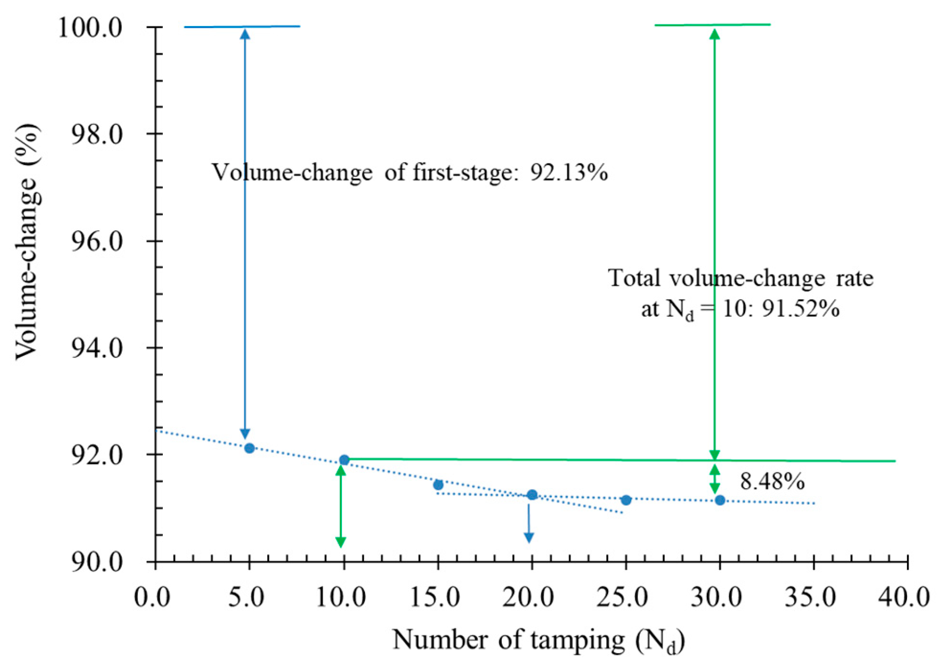
3.1. Ground Volume Change by Dynamic Compaction

The volume change before and after the construction of the dynamic compaction pounder was measured at each stage of tamping. The volume change of the ground due to step-by-step dynamic compaction was measured using a level at the pounder tamping point. Notably, changes in the height and ground volume decreased with the number of pounder tamping repetitions. The differences were validated by the settlement heights of each tamping stage based on the initial ground height. The change in settlement and ground volume caused by pounder tamping decreased as the number of tamping increased (Figure 4). The step-by-step volume change attributed to the pounder tamping was 7.87%, 8.09%, 8.56%, 8.75%, 8.84%, and 8.84%. The largest volume change, a decrease of 5.47%, was observed in step three (Nd = 15), as it converged from step four (Nd = 20). Menard and Broise (1975) reported that the minimum number of tamping can be determined when the increase in settlement due to dynamic compaction is less than 10% of the total settlement [24]. In this study, the settlement in step two (Nd = 10) was 8.48% of the total settlement. However, as the settlement converged after step three (Nd = 15), the minimum number of tamping is recommended to be set at 15.

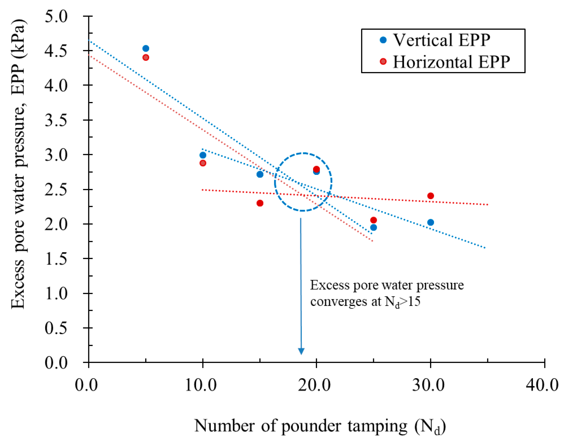
3.2. Change in Excess Pore Water Pressure (EPP)

The change in excess pore water pressure of the ground caused by the step-by-step of pounder tamping increase in Ev was measured. In particular, the excess pore water pressure decreased in both the vertical and horizontal directions with stepwise increments in the Ev. The excess pore water pressure in vertical and horizontal directions is shown in Figure 5. The average EPP for each stage was 4.40 kPa in the vertical direction and 4.54 kPa in the horizontal direction in step one, 2.88 kPa in the vertical direction and 2.99 kPa in the horizontal direction in step two, 2.30 kPa in the vertical direction and 2.72 kPa in the horizontal direction in step three, 2.79 kPa in the vertical direction and 2.75 kPa in the horizontal direction in step four, 2.05 kPa in the vertical direction and 1.95 kPa in the horizontal direction in step five, and 2.41 kPa in the vertical direction and 2.03 kPa in the horizontal direction in step six. As for the vertical and horizontal EPP, the EPP decreased as the number of pounder tamping repetitions increased. Xu and Hu (2017) reported similar results, essentially indicating that the EPP induced by dynamic compaction decreases with an increase in compaction energy and depth [25]. This finding implies that the strength of the ground increases owing to step-by-step dynamic compaction. In addition, it converges at the pounder tamping step three (Nd = 15) or at higher steps. Moreover, the effect of dynamic compaction was up to 4.0 m in the vertical direction and 3.0 m in the horizontal direction. These results demonstrate that the ground was efficiently improved by performing step-by-step dynamic compaction wherein tamping was performed alternately according to the diameter of the pounder. Bonab and Zare (2014) also analyzed the effect of tamping space and pattern on dynamic compaction, and thereby revealed that the ground improvement is enhanced by alternately performing tamping patterns at adjacent points, which is consistent with our results [26]. Essentially, dynamic compaction is effective for ground improvement in all directions.
Figure 6 plots the numerical analysis results for the change in EPP upon pounder tamping. Finite element analysis AFIMEX GT-2D was used for numerical analysis. Figure 6b shows the modeling results of Figure 6a digitized and expressed as a graph. The numerical analysis revealed that the pore water pressure increased from 3.19 to 11.5 kN/m2 in the vertical and from 0.23 to 2.21 kN/m2 in the horizontal directions at the bottom of the tamping point. Further, the EPP occurred most frequently within 3.0 m in the vertical and horizontal directions. This conforms to the results of the soil box test, thus indicating that dynamic compaction is effective in the vertical and horizontal directions.
Figure 7 illustrates the numerical analysis results for the effects’ range of dynamic compaction applied to the in situ ground. This analysis revealed that the effect range of dynamic compaction energy overlapped in the vertical and horizontal directions, enabling the improvement of even the lower ground. Therefore, by adjusting the Ev and Nd of the pounder, a ground improvement plan suitable for site characteristics can be established.

3.3. Change in Ground Strength

Figure 8 presents the results of the static cone penetration test after dynamic compaction. The static cone penetration test was able to measure up to a depth of 0.8 m of ground of the soil box before dynamic compaction. However, as the step-by-step dynamic compaction test progressed, the measurements were limited to a depth of 0.4 m. Presumably, this limitation occurred because the relative density increased as the dynamic compaction Ev in each step was transmitted to the lower part of the ground. As illustrated in Figure 8, the effect of ground improvement was not significant until step one (Nd = 5) compared with static cone penetration resistance before dynamic compaction. Starting from step two (Nd = 10), the static cone penetration resistance increased with the compaction depth. The difference in static cone penetration resistance by depth was 1806.26 kPa in step one (Nd = 5), whereas it increased by a factor of 2.93 to a pressure of 4635.76 kPa in step two (Nd = 10), and by a factor of 3.87 to 6115.12 kPa in step six (Nd = 30). The static cone penetration resistance at the ground surface increased by a factor of 1.33 in step two (Nd = 10); however, the highest increase in its value (by a factor of 1.65) occurred in step three (Nd = 15). These findings suggest that a minimum of 15 tamping repetitions (Nd = 15) is required for ground strength improvement through dynamic compaction.

3.4. Analysis of Improvement Effect by Dynamic Compaction

The improvement depth in dynamic compaction is determined using the relational expression of energy per tamping repetition proposed by Menard and Broise (1975) [24]. The empirical formula is determined by the improvement depth coefficient, the weight of pounder, and the height of the tamping. Nd can be expressed as the relationship between the depth of improvement and Ev. The coefficient value that determines these relationships is called the depth of improvement coefficient (α). During the dynamic compaction of the soil box test, α was inversely calculated using the weight and fall height of the pounder. Based on the soil box test results, the ground improvement depth coefficient calculated inversely was compared with the results proposed by Menard and Broise (1975). The α proposed by Menard and Broise (1975) ranges from 0.4 to 0.6 for sandy soil, from 0.5 to 0.7 for crushed stone and gravel, and from 0.3 to 0.5 in waste ground.
In this study, the α for the soil box test was in the range of 0.26–0.52 (Figure 9a). The depth of improvement coefficients of previous researchers is summarized in Table 3. Compared with previous studies, the depth of improvement coefficient in this study exhibited a slightly lower range of values. However, domestic researchers, Jang et al. (2009) [27] and Lee and Kim (1996) [28], reported a range of values similar to the depth of improvement coefficient. The variation in the improvement depth coefficient may be attributed to differences in soil formation history by region, soil type, and empirical correlation data.
In this study, the improvement depth coefficient (α) is a crucial parameter for controlling the efficiency of dynamic compaction, ensuring a balance between the pounder weight and tamping height. Moreover, Li et al. (2020) reported that to control the efficiency of dynamic compaction, the same compaction efficiency can be obtained by maintaining a constant weight and tamping height of the pounder while altering the α [29]. The α value measured in this study was smaller than that proposed by Menard and Broise (1975) for sandy soil ground. In addition, the soil box test condition has a relatively large effect on dynamic compaction owing to the constraint of the wall and floor; thus, the depth of improvement can be further increased. Therefore, for field applications, the weight and tamping height of the pounder must be maintained and the appropriate α value, as suggested in this study, must be applied as demonstrated by Li et al. (2020) [29].
Based on these relationships, the change in ΔN of the soil box test can be inferred from the relationship between the cone penetration resistance value and the standard penetration resistance value. ΔN (change of N) is defined by the relationship between the static cone penetration resistance and SPT-N proposed by Meyerhof (1954) [30]. The internal friction angle is defined as a relational expression corresponding to rounded, uniform-grained soil particles, as proposed by Dunham (1954) [31]. The ΔN and internal friction angle, converted from the results of the static cone penetration test, allow for the estimation of changes in the internal friction angle and ΔN of the improved ground in advance based on the correlation with the number of pounder tamping repetitions (Figure 9b). This information can be utilized to determine the energy for compaction (weight of pounder and height of tamping).
Table 3. Depth of improvement coefficient of previous researchers.
ResearcherSoil Typeα
Menard and Broise (1975) [24]Silty sands0.4–0.6
Mayne (1984) [32]Silty sands0.5
Lukas (1995) [32]Generally soil0.3–0.8
Lee and Kim (1996) [28]Generally soil0.31–0.64
Jang et al. (2009) [27]Sands0.25–0.48
Lee et al. (2010) [15]Silty sands0.55–0.85
Elreedy (2017) [33]Finer-grained soils0.3–0.7
Pastel (2019) [34]Generally soil0.4–0.8
Li et al. (2020) [29]Sands>0.5
Zhang et al. (2021) [20]Silty clay0.8

4. Conclusions

A dynamic compaction test was conducted on the dredging landfill of the soil box. The test considered the volume change according to the change in dynamic compaction energy (the number of pounder tamping repetitions), the change in excess pore water pressure (EPP), the change in ground strength, and the range of influence of dynamic compaction. Based on the findings, the following conclusions are drawn.
  • The volume change caused by step-by-step pounder tamping was reduced. After the volume change of 5.47% in the third stage (Nd = 15), it converged from the fourth stage (Nd = 20). To determine the minimum number of tamping repetitions when the settlement increase is less than 10% of the total settlement, it is recommended to set the minimum number of tamping to 15, because the volume change decreases after the third stage (Nd = 15).
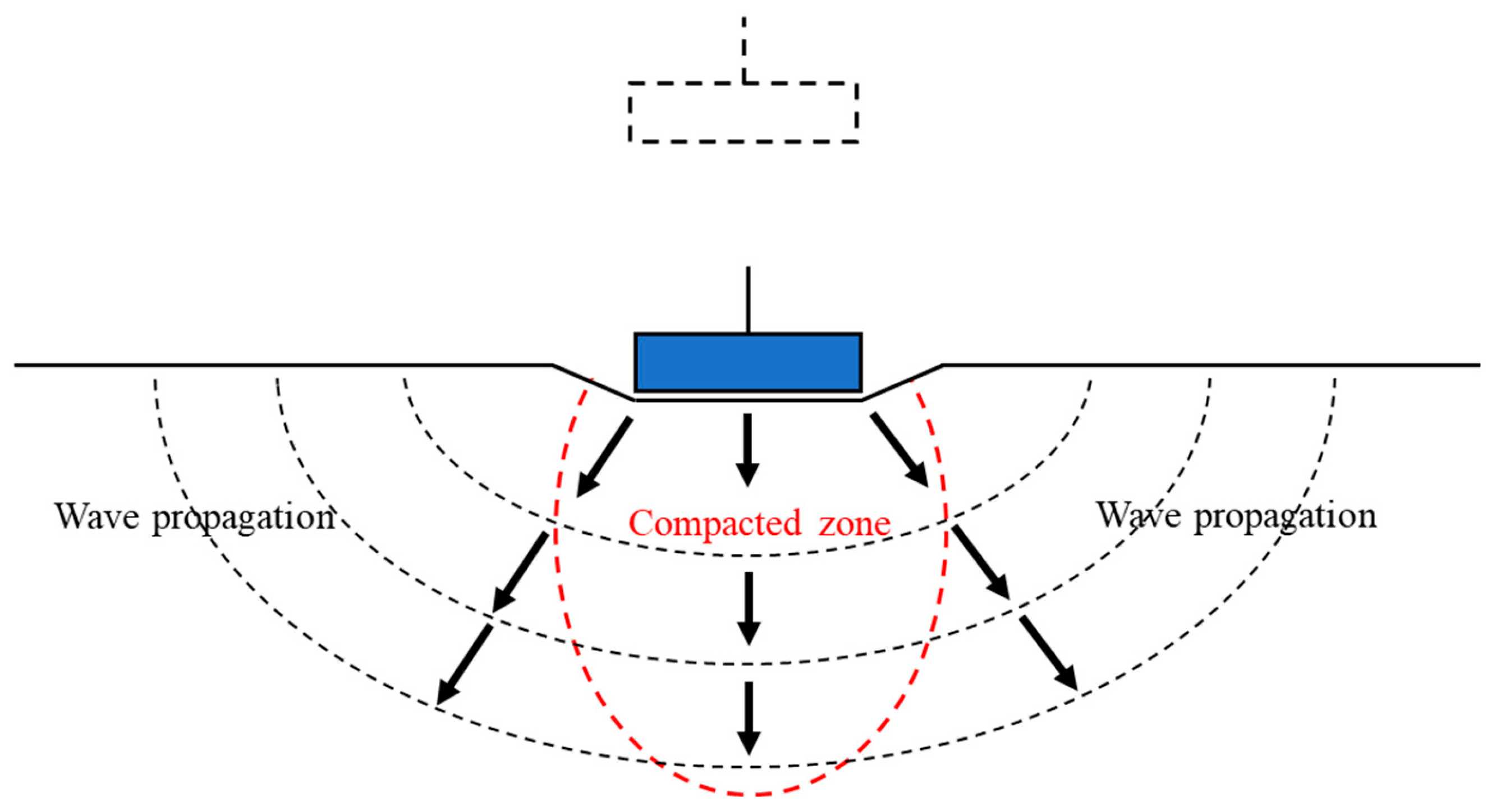
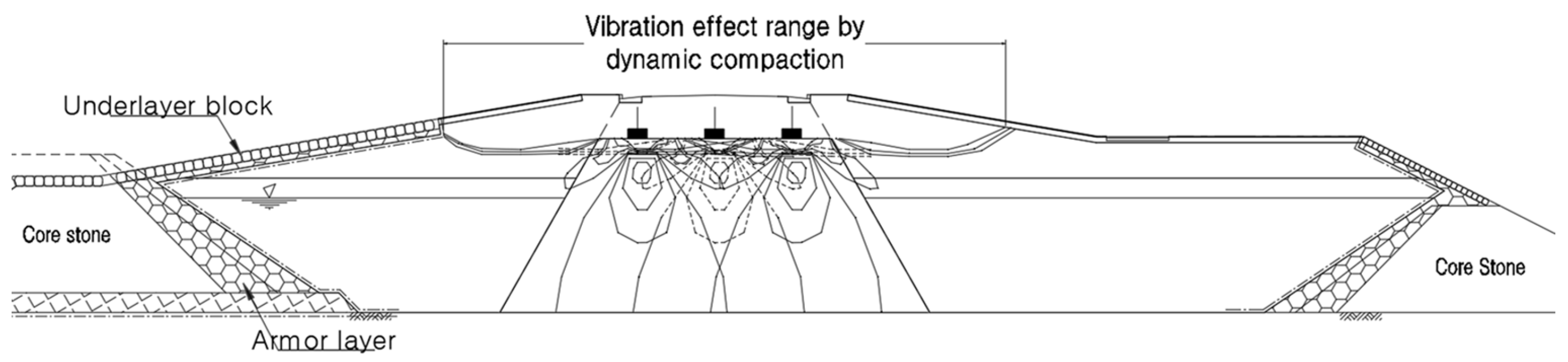
  • The vertical and horizontal EPP changes caused by the pounder tamping decreased as the step-by-step Ev increased. Similar to the volume change, the EPP converged at the third stage (Nd = 15) or at higher stages. The dynamic compaction effect was observed up to a depth of 4.0 m vertically and 3.0 m horizontally. A comparison of the numerical analysis results and the range of ground improvement revealed that the range of ground improvement was identical to the result of the soil box test, as EPP occurred most frequently within 3.0 m. These results indicate that the ground was efficiently improved by performing step-by-step dynamic compaction with alternate tamping as much as the diameter of the pounder.
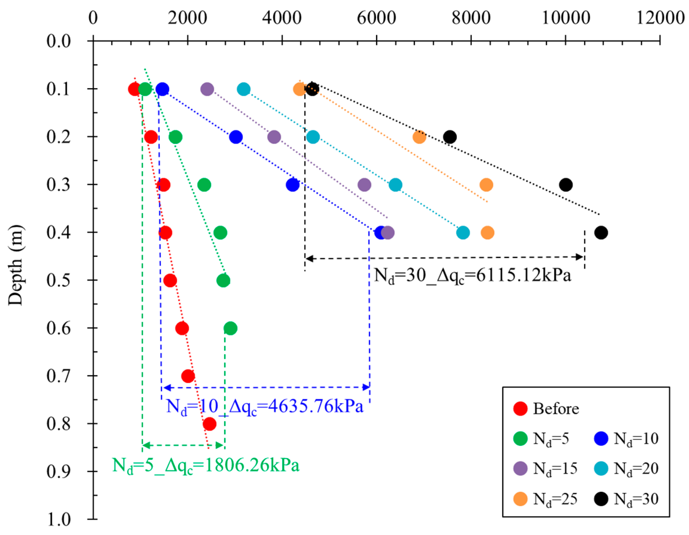
  • Owing to the ground improvement effect obtained through step-by-step dynamic compaction, the static cone penetration test of the soil box was limited to a depth of 0.4 m, thus presenting a 50% reduction in the measurable depth after dynamic compaction. The cone penetration resistance at the ground surface, determined by the static cone penetration test, exhibited the maximum increase in the third stage (Nd = 15) by a factor of 1.7.
  • The improvement depth coefficient (α) analyzed in the results of this study was smaller than that proposed by Menard and Broise (1975) for sandy soil ground (0.4–0.6). To maintain a constant pounder weight and tamping height and to control the efficiency of dynamic compaction, α within the range of 0.26–0.52 can be suggested. In addition, based on the soil box test results, the correlation between the number of tamping repetitions, ΔN, and the internal friction angle can be utilized to estimate the improvement effect of in situ ground and determine the in situ dynamic compaction energy.
The method proposed in this study can be economically applied for ground improvement within a short period. When considering the effect of ground improvement through dynamic compaction, the depth of improvement, tamping energy, spacing of tamping points, and number of tamping repetitions must be considered. However, the soil box test in this study did not allow for a comprehensive consideration of tamping point spacing and pounder tamping height due to the challenges posed by repetitive testing. Therefore, further studies should be conducted to address these aspects.

Funding

This research received no external funding.

Data Availability Statement

The data used to support the findings of this study are included within the article.

Conflicts of Interest

The author declares no conflict of interest.

Appendix A

Figure A1. Soil box and pore water pressure sensors installation: (a) installation of pore water pressure sensor; (b) dredging landfill ground.
Buildings 13 01830 g0a1
Figure A2. Schematic layout of dynamic compaction procedure to pounder tamping: (a) dynamic compaction procedure; (b) dividing the pounder tamping position of soil box.
Buildings 13 01830 g0a2
Figure A3. Dynamic compaction test front view and ground condition after dynamic compaction: (a) front view of soil box test of dynamic compaction pounder; (b) excess pore water pressure after dynamic compaction.
Buildings 13 01830 g0a3
Figure A4. Measurement of ground strength changes by static cone penetration test: (a) static cone penetration test before dynamic compaction; (b) static cone penetration test after dynamic compaction.
Buildings 13 01830 g0a4

References

  1. Nam, H.K. A Study on the Improvement Depth of Dynamic Compaction Method Applied to Selected Soils of Waste Landfill. Doctoral Dissertation, Sangji University, Wonju, Republic of Korea, 2018. [Google Scholar]
  2. Hamidi, B.; Nikraz, H.; Varaksin, S. A review on impact oriented ground improvement techniques. Aust. Geomech. 2009, 44, 17–24. [Google Scholar]
  3. Loos, W. Comparative studies of the effectiveness of different methods for compacting cohesionless soils. In Proceedings of the 1st International Conference on Soil Mechanics and Foundation Engineering, Cambridge, MA, USA, 22–26 June 1936; Volume 3, pp. 174–179. [Google Scholar]
  4. Mayne, P.W.; Jones, J.S.; Dumas, J.C. Ground response to dynamic compaction. J. Geotech. Eng. 1984, 110, 757–774. [Google Scholar] [CrossRef]
  5. Bo, M.W.; Na, Y.M.; Arulrajah, A.; Chang, M.F. Densification of granular soil by dynamic compaction. Proc. Inst. Civ. Eng. Ground Improv. 2009, 162, 121–132. [Google Scholar] [CrossRef]
  6. Khelalfa, H. Dynamic compaction with high energy of sandy coastal embankment. In Proceedings of the International Symposium on Construction Management and Civil Engineering (ISCMCE, 2017), Skikda, Algeria, 15–16 November 2017. [Google Scholar]
  7. Ali, L.; Ali, S. Enhancement of bearing capacity by dynamic compaction: A case history. In Proceedings of the 6th International Conference on Case Histories in Geotechnical Engineering, Arlington, VA, USA, 11–16 August 2008; Volume 7.25a, pp. 1–11. [Google Scholar]
  8. Lee, F.H.; Gu, Q. Method for estimating dynamic compaction effect on sand. J. Geotech. Geoenviron. Eng. 2004, 130, 139–152. [Google Scholar] [CrossRef]
  9. Kundu, S.; Viswanadham, B.V.S. Studies to evaluate the impact of tamper on the depth of improvement in dynamic compaction. In Proceedings of the 15th Asian Regional Conference on Soil Mechanics and Geotechnical Engineering, Fukuoka, Japan, 9–13 November 2015; Japanese Geotechnical Society Special Publication: Bunkyo, Japan, 2016; Volume 2, pp. 2033–2037. [Google Scholar] [CrossRef]
  10. Shen, M.; Martin, J.R.; Ku, C.; Lu, Y. A case study of the effect of dynamic compaction on liquefaction of reclaimed ground. Eng. Geol. 2018, 240, 48–61. [Google Scholar] [CrossRef]
  11. Lee, I.M.; Kim, J.H.; Choi, Y.J. Dynamic compaction Technique for Ground Improvement: A case Study. Archit. Inst. Korea 1993, 13, 743–746. (In Korean) [Google Scholar]
  12. Kim, J.K.; Chae, Y.S. A Study on the Evaluation of the Effect of the Ground Improvement of Reclaimed Land Based on Dynamic Compaction Method. J. Korean Geotech. Soc. 2006, 22, 13–26. [Google Scholar]
  13. Lee, B.J.; Youn, J.S.; Lee, J.K. Estimation of Depth of Improvement by Dynamic Compaction with Soil Conditions. Korean Geo-Environ. Soc. 2005, 6, 55–61. [Google Scholar]
  14. Wrryu, W.R.; Byun, Y.S.; Lee, J.B.; Kim, K.M.; Chun, B.S. A Case Study on Shallow Foundation Design of the Reclaimed Land Based on Dynamic Compaction Method. Korean Geo-Environ. Soc. 2010, 11, 51–59. [Google Scholar]
  15. Lee, J.H.; Lim, D.S.; Chun, B.S. Numerical Study on the Prediction of the Depth of Improvement and Vibration Effect in Dynamic Compaction Method. J. Korean Geotech. Soc. 2010, 26, 59–66. [Google Scholar]
  16. Mieloszyk, E.; Milewska, A.; Wyroslak, M. Blast charge technique as a method of soil improving to locate the new supporting runways. IOP Conf. Ser. Mater. Sci. Eng. 2019, 603, 052025. [Google Scholar] [CrossRef]
  17. Yao, K.; Yao, Z.; Song, X.; Shang, Q. Test study of pore water pressure during dynamic compaction at the subgrade of highway in the Yellow River flood area. Adv. Mater. Res. 2012, 374–377, 436–439. [Google Scholar] [CrossRef]
  18. Shaban, A. Dynamic Compaction; Indian Institute of Engineering Science and Technology: Howrah, India, 2018. [Google Scholar]
  19. Jiang, C.; Ge, Y.; Wang, B.; Zhang, L.; Liu, Y. Impact of the High-Energy Dynamic Compaction by Multiple Compactors on the Surrounding Environment. Adv. Civ. Eng. 2021, 2021, 6643064. [Google Scholar] [CrossRef]
  20. Zhang, x.; Yang, M.; Han, Y. Model test study on the effect of dynamic compaction under low water content. PLoS ONE 2021, 16, e0253981. [Google Scholar] [CrossRef] [PubMed]
  21. Hamidi, B.; Nika, H.; Varaksin, S. Dynamic compaction vibration monitoring in a saturated site. In Proceedings of the International Conference on Advances in Geotechnical Engineering, Perth, Australia, 7–9 November 2011; pp. 267–272. [Google Scholar]
  22. Kim, Y.M.; Lee, S.Y.; Kim, M.G.; Shin, S.C. Assessment of dynamic deep compaction applied to waste Landfill. J. Korean Soc. Civ. Eng. 1993, 13, 209–222. (In Korean) [Google Scholar]
  23. ASTM D 3441-98; Standard Test Method for Mechanical Cone Penetration Tests of Soil. American Society for Testing and Materials: West Conshohocken, PA, USA, 1998.
  24. Menard, L.; Broise, Y. Theoretical and practical aspects of dynamic consolidation. Géotechnique 1975, 25, 3–18. [Google Scholar] [CrossRef]
  25. Xu, Y.; Hu, P. A pore water model of dynamic compaction. In Proceedings of the Advances in Materials, Machinery, Electrical Engineering (AMMEE 2017), Tianjin, China, 10–11 June 2017; Volume 114, pp. 1–4. [Google Scholar] [CrossRef] [Green Version]
  26. Bonab, M.H.; Zare, F.S. Investigation on tamping spacing in dynamic compaction using model tests. Ground Improv. 2014, 167, 219–231. [Google Scholar] [CrossRef]
  27. Jang, Y.S.; Song, Y.S.; Jeon, H.Y. Application of Dynamic Compaction for Finished Landfill. In Proceedings of the Korean Geotechical Society Conference, Seoul, Republic of Korea, 25–26 September 2009; pp. 1472–1477. [Google Scholar]
  28. Lee, S.W.; Kim, M.M. Expert System for Dynamic Compaction Method. Korean Soc. Civ. Eng. 1996, 16, 181–191. [Google Scholar]
  29. Li, X.; Zhang, K.; Ma, X.; Teng, J.; Zhang, S. New Method to Evaluate Strengthen Efficiency by Dynamic Compaction. Int. J. Geomech. 2020, 20, 04020024. [Google Scholar] [CrossRef]
  30. Meyerhof, G.G. Correlation between penetration tests and the bearing capacity of cohesionless soils. In Proceedings of the Eighth Canadian Soil Mechanics Conference, Ottawa, ON, Canada, 16–17 December 1954; pp. 12–19. [Google Scholar]
  31. Dunham, J.W. Pile Foundations for Buildings; American Society of Civil Engineers, Soil Mechanics and Foundation Division: Reston, VA, USA, 1954. [Google Scholar]
  32. Lukas, R.G. Geotechnical Engineering Circular No. 1—Dynamic Compaction; Ground Engineering Consultants, Inc.: Englewood, CO, USA, 1995. [Google Scholar]
  33. Elreedy, M. Onshore Structural Design Calculations: Soil Investigation and Pile Design. In Power Plant and Energy Processing Facilitie; Elsevier: Amsterdam, The Netherlands, 2017; pp. 345–385. [Google Scholar] [CrossRef]
  34. Patel, A. Geotechnical Investigations and Improvement of Ground Conditions: Soil compaction. In Woodhead Publishing Series in Civil and Structural Engineering; Elsevier: Amsterdam, The Netherlands, 2019; pp. 7–18. [Google Scholar] [CrossRef]
Figure 1. Dynamic compaction. Propagation of vibrations (waves) in the ground [16].
Buildings 13 01830 g001
Figure 2. Geographical location of dredged soil collection.
Buildings 13 01830 g002
Figure 3. Process of soil box test of dynamic compaction.
Buildings 13 01830 g003
Figure 4. Volume change with the number of tamping.
Buildings 13 01830 g004
Figure 5. Volume change with number of pounder tamping repetitions.
Buildings 13 01830 g005
Figure 6. Changes in excess pore water pressure by numerical analysis: (a) excess pore water pressure range in numerical analysis; (b) comparison of EPP of numerical analysis and soil box.
Buildings 13 01830 g006
Figure 7. Impact range of dynamic compaction by numerical analysis results.
Buildings 13 01830 g007
Figure 8. Cone penetration resistance for the number of pounder tamping repetitions in each stage.
Buildings 13 01830 g008
Figure 9. Coefficient α and correlation between the number of pounder tamping repetitions by soil box test: (a) improvement depth coefficient α; (b) correlation between the Nd.
Buildings 13 01830 g009
Table 1. Physical characteristics of dredged soil.
SoilWn (%)GsPassing through 0.075 mmLL (%) γ d
(kN/m3)
USCS
Dredged soil25.22.6840.7NP12.34–16.82SM
wn: natural water content; Gs: specific gravity; LL: liquid limit; NP: non-plastic; γd: dry unit weight; USCS: unified soil classification system; SM: silty sands or sand–silt mixtures soil.
Table 2. Nd and Ev at each stage in the soil box test.
Step123456
Nd = 5Nd = 10Nd = 15Nd = 20Nd = 25Nd = 30
Ev (kN·m/m3)9.820.630.441.251.061.8
Disclaimer/Publisher’s Note: The statements, opinions and data contained in all publications are solely those of the individual author(s) and contributor(s) and not of MDPI and/or the editor(s). MDPI and/or the editor(s) disclaim responsibility for any injury to people or property resulting from any ideas, methods, instructions or products referred to in the content.

