Abstract
Although the use of 3D printing in civil engineering has grown in popularity, one of the primary challenges associated with it is the absence of steel bars inside the printed mortar. As a result, developing 3D printing mortar with ultra-high compressive, flexural, and tensile strengths is critical. In the present study, an ultra-high-performance mortar incorporating silica fume (SF) and graphene nanoplatelets (GNPs) was developed for 3D printing application. The concrete mixture added SF to the concrete mixture in the range between 0% and 20%, while GNPs were added as a partial replacement by cement weight from 0.5% to 2%. The flowability and the machinal properties of the proposed mortar, including compressive (CS), tensile (TS), and flexural strength (FS), were investigated and assessed. Microstructure analysis involving FESEM and EDX was also investigated and evaluated, while response surface methodology (RSM) was considered to predict and optimize the optimum value of GNPs and SF. Workability results show that the flowability is reduced when the amount of graphene increases. Based on the predicted and experimental results, ultra-high-strength mortar can be developed by including 1.5% of GNPs and 20% of SF, in which the CS jumped from 70.7 MPa to 133.3 MPa at the age of 28 days. The FS and TS were 20.66 MPa and 14.67 MPa compared to the control mix (9.75 MPa and 6.36 MPa), respectively. This favorable outcome was credited to the pozzolanic activity of SF and the effectiveness of GNPs in compacting the pores and bridging the cracks at the nanoscale level, which were verified by FE-SEM and EDX. In addition, the developed quadratic equations proved their accuracy in predicting and optimizing the mechanical properties with low error (less than 0.09) and high correlation (R2 > 0.97). It can be concluded that the current work is an important step forward in developing a 3D printing mortar. The lack of reinforcement in the printed mortar structure has been a considerable difficulty, and the SF and GNPs have increased the compressive, flexural, and tensile strengths of the mortar. Thus, these improvements will encourage the industry to utilize sustainable materials to produce more affordable housing.
1. Introduction
Traditional concrete construction often faces challenges such as high costs, decreased safety, and increased time and effort [1,2,3]. To address these issues, the civil engineering community has turned its attention towards adopting a new construction technique known as 3D concrete printing [4,5,6]. This unique technique, paired with precise structural optimization [7,8], holds the key to massive benefits by substantially decreasing the wastage of building materials. Furthermore, the removal of formwork not only reduces both money and time but also opens up a world of possibilities for projects of all sizes, from small-scale to large-scale constructions. It is important to embrace the sustainability perspective, using a logical approach when selecting the most efficient 3D concrete printing technology. A thorough study needs to take place to determine the regions where this advanced technology offers the most potential and benefits compared to traditional building methods. Despite the available research falling short of fully investigating the sustainability implications of 3D concrete printing, the limited studies provide solid evidence of its enormous potential when it requires complex designs for conventional construction [9].
Three-dimensional concrete printing is one of the latest technologies that has shifted from laboratory experiments to developing different types of projects such as multi-story units, gardens, bridges, etc. [10]. All of these developments require Portland cement PC, and the high demand for utilizing PC is excessively predicted to be 4–8 Gt/yr by 2100 from the perspective of shared socioeconomic pathways [11,12]. PC production causes high CO2 emissions, accounting for 7–10% of global anthropogenic CO2 emissions and 2–3% of energy consumption, and it is projected that cement production will increase by 50% by 2050 [13,14,15]. To reduce CO2 emissions, scientists found four methods [16,17,18], which currently follow the standard proposed by the World Business Council for Sustainable Development (WBCSD) and International Energy Agency (IEA) in the cement industry [19].
This technology offers numerous benefits to the construction industry, including cost-effectiveness, reduced effort, and improved safety compared to traditional concrete construction [20,21]. However, a major challenge in 3D printing concrete is the absence of steel reinforcement during the printing process. This has prompted researchers to focus on designing 3D-printed concrete with ultra-high mechanical properties, ensuring high compressive, tensile, and flexural strength. The research and development of 3D concrete printing have progressed through sequential steps. In the first step, researchers focused on developing 3D-printed concrete having low compressive strength. Subsequently, efforts were made to enhance the 3D printing concrete mix to achieve high-quality results, including high compressive, flexural, and tensile strength, as there is no steel reinforcement.
For example, Wolfs, Bos [22] started to develop 3D concrete printing with a compressive and flexural strength of 30 MPa and 5 MPa, respectively. Cement I 52.5, fine aggregate (less than 1 mm), polypropylene (PP) fibers, rheology modifiers, and additives were used to achieve the aim of their study. The water-to-cement ratio was kept constant (0.495). Similarly, Ding, Xiao [23] developed 3D printing green mortar with a low compressive and flexural strength of 19.31 MPa and 2.15 MPa, respectively. After that, Lee, Kim [4], in turn, tried to use pozzolanic additives such as silica fume (SF) and fly ash (FA) as partial replacements for cement (OPC) to enhance the strength of 3D printing concrete. The outcome exposed that the compressive strength of the reference mixture using mold-casting samples was 66 MPa after 28 days, while it decreased to 22.54 MPa using printed cubical samples. Similarly, Narelle, Hempel [24] developed 3D printing concrete involving 55% cement I 52.5, 15% silica fume, 30% fly ash, and a water-to-binder ratio of 0.42. It was found that the compressive strength of 3D printing mortar incorporating pozzolanic additives increased by 30% compared to that of the control mixture (71.8 MPa). The strength enhancement was linked to the pore refinement at the micro-scale level in the presence of pozzolanic additives inside the cement-based matrix. Arunothayan et al. [25], in the same context, used fiber to improve the mechanical properties of 3D printing concrete, and it is in good agreement with [26]. To further enhance the strength gained at the nanoscale level, nanomaterials were also taken into account in 3D printing mortar. For example, Panda, Lim [27] suggested adding 0.5% of nano clay in a 3D-printable mortar mixture incorporating high fly ash content up to 60%, 2% silica fume, and 38% ordinary Portland cement. The water-to-cement ratio was 0.3, and the sand-to-binder ratio was 0.83. Sikora, Chung [28] used nano-silica in the range between 2% and 6% in printable cement mortar containing OPC, limestone filler, and fine aggregate.
In addition, other researchers shifted their attention to utilizing nanocarbon materials, namely graphene, as cement replacements [29]. However, its incorporation in 3D printing concrete is still in its infancy, and very little research has been conducted on the impact of graphene on ultra-high-strength 3D printing mortar. Indeed, graphene is regarded as one of the most robust materials in the globe, as the tensile strength of graphene reaches up to 130 GPa, and its Young’s modulus is recorded up to 1 TPa [30]. According to K. Cui and J. Chang [31], the research found that adding MLG can significantly enhance compressive strength and flexural strength on the 28th day by 22.2% and 43.3%, respectively. Shanmuga Priya, Mehra [32] also concluded that the GO serves as a beneficial reinforcement material inside the concrete matrix. Although GO has benefits when mixed with cement, an excess of oxygen functional groups in GO can cause problems in the cement-based matrix. This is because the positive charge of Ca2+, Na+, and K+ in the cement matrix and the negative charge of GO can cause agglomeration due to van der Waals forces, resulting in the formation of a weak zone within the cement-based matrix [33]. In another study conducted by Kei cui et al. [19], which studied the impact of CNTs on the UHPC with two different dosages (0.09%, 0.15%), the results show great strength of the concrete, which contain CNTs with a large aspect ratio of 250–1500. Therefore, instead of GO, researchers have focused on using reduced graphene oxide [34,35] and graphene powder (graphene nanoplatelets) [36] to improve cementitious materials. For example, Jiang, Sevim [37] noticed that the highest compressive strength of concrete was 17% when the GNPs were incorporated into the concrete mixture at a dosage of 0.025% by cement weight. The result was in line with Wang, Jiang [38], who found that the flexural strength of a cement composite increased by approximately 20% (average) when the content of GNPs was just 0.05%. In contrast, Du, Gao [39] stated that adding a high level of graphene nanoplatelets (up to 1.5%) can significantly densify concrete pores. This is in good agreement with Du and Dai Pang [40], who demonstrated that incorporating 2.5% of graphene nanoplatelets in cement mortar can significantly increase the refinement of the mortar microstructure compared to the control mix without GNPs. Jiang, Sherif [41] also reported that the graphene nanoplatelets are able to bridge the inevitable cracks inside the concrete and enhance the tensile strength by 8–48%.
Based on the overmentioned, the development of ultra-high mechanical properties of 3D printing mortar is in urgent demand to promote the use of 3D printing technology in the construction field. In addition, incorporating graphene in a cement-based matrix not only enhances the compressive strength by filling the concrete pores at the nanoscale level but also acts as reinforcement by bridging the cracks. Therefore, to fill the gap in the present literature, ultra-high-performance 3D printing mortar incorporating graphene nanoplatelets and silica fumes has been developed. The dosage of GNPs varied from 0% to 1.5% at intervals of 0.5%, while silica fume content ranged between 0% and 20% of the cement replacement. The proposed mortar’s mechanical properties, such as compressive, flexural, and tensile strength, are investigated and analyzed via both experimental and mathematical modeling. Response surface methodology (RSM) is also used as a mathematical and statistical tool to predict and find the optimum content of graphene nanoplatelets and silica fume, as well as to derive a quadratic equation for further prediction in the future. Microstructural tests such as field emission scanning electron microscopy (FE-SEM) are also adopted to evaluate the behavior of the proposed mortar at the micro- and nanoscale levels.
2. Experimental and Theoretical Program Set-Up
2.1. Materials Preparation
The proposed high-strength mortar comprises cement, silica fume, graphene, natural sand, superplasticizer, and water. Figure 1 depicts the graphene morphology purchased from GrapheneCA Inc. (NYC, New York, NY, USA). It can be seen that graphene is composed of multiple layers, which are well known as graphene nanoplatelets. A rapidly hardened and early-strength cement (cement I 52.5 R) was used as it was recommended for ultra-high-strength 3D printing mortar. Silica fume was, in turn, used as a mineral admixture, which was supplied by Elkem company. Table 1 shows the chemical composition of both silica fume and cement as determined by X-ray fluorescence (XRF) spectroscopy. It can be seen that the silica fume is rich in SiO2 (greater than 93%), which is in line with previous studies [7]. A laser diffraction particle size analyzer was also used to determine and analyze the particle size distribution of silica fume and cement. Based on Figure 2, the size of silica fume particles was smaller than the cement particles, with median particle sizes of 12.74 µm and 13.505 µm, respectively. This fact confirmed the advantage of the undersized silica fume to fully react with calcium hydroxide ions and ultimately provide more gel product in the mortar matrix.
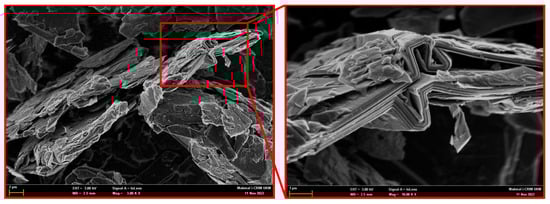
Figure 1.
Graphene morphology (FESEM image).

Table 1.
Chemical composition of silica fume and cement based on XRF analysis.
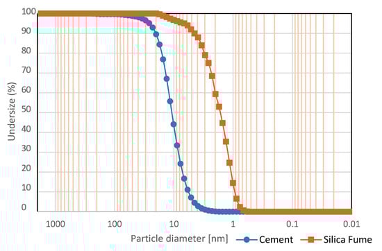
Figure 2.
Particle size distribution for both silica fume and cement.
As the fine aggregate, local natural sand was also used. The natural sand’s particle size distribution and fineness modulus were determined using a sieve analysis test in accordance with ASTM C33-18 [42]. It was found that the sand met the grading requirements in which the passing on all sieves (4.75 mm–0.075 mm) was located between the high and low limits of the specification, as shown in Figure 3. In addition, the fineness modulus, water absorption, and specific gravity of sand were 2.3, 2.6, and 1.2%, respectively. For workability, it is interesting to note that three different superplasticizers were used and tested. Based on the optimum results that gave a high slump without any segregation, Superplasticizer RPF RAPIDCAST W, which was purchased from Real Point Sdn Bhd, was taken into account for our study at a dosage level of 1% by cement weight.
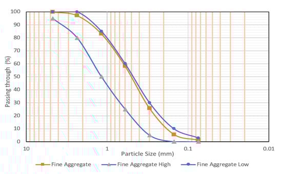
Figure 3.
The grading of natural sand according to ASTM C33.
2.2. Mix Proportions
The research has a set of three scenarios that were methodically designed to comprehensively examine the behavior of ultra-high-performance mortar injected with the potent mixture consisting of silica fume and graphene. These situations established fifteen separate experiments, as comprehensively detailed in Table 2. In this initial scenario, the UHP mortar mixture contained a range of GNPs concentrations varying from 0% to 2% of the cement weight, with consistency at every 0.5% increment. It is important to note that silica fume was purposefully avoided, adding an element of tension to the research process. The mortar, equipped with unparalleled strength provided by graphene (0% to 2%), was further reinforced in the second and third scenarios by incorporating 10% and 20% silica fume. These remarkable combinations pushed boundaries for technological advancement to unprecedented heights. The cement-to-fine-aggregate ratio was set as the optimum at 1:1 by mass in all of the developed mixtures, while the water-to-cement ratio of 0.26 ensured excellent stability in the mixture. Notably, adding silica fume at concentrations of 0.1 and 0.2 provided a distinct presence for the mortar. A minimum of 1% superplasticizer dosage was effectively incorporated to ensure continued consistency and facilitate subsequent comparisons and assessments, maintaining the water content at a constant level across every mixture. The 3D printing mortar workability has been carefully gauged, with this experiment flow table illustrated in Figure 4, in strict conformity to the revered standards set out by ASTM C230 [43].
Table 2.
Mix proportions of the proposed mortar.
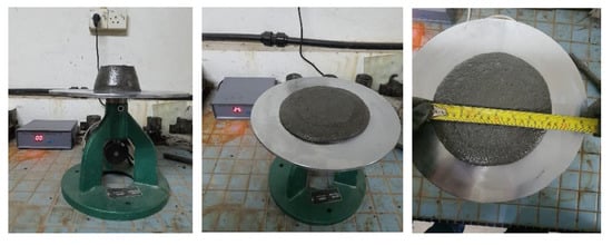
Figure 4.
Workability of graphene-based mortar using flow table.
2.3. Compressive Strength Test
The compressive strength of the proposed mortar was determined at 3, 7, 14, and 28 days. Based on the guidelines of ASTM C109-109M [44], the procedure was carried out using a cubic sample measuring 50 × 50 × 50 mm with three replicates. The cubic sample was placed on the compression machine and exposed to a constant load rate of 1000 N/s until failure occurred, as stipulated by the standard. The cubic compressive strength (CS) in MPa was then calculated using Equation (1), which takes into account the measured failure load as well as the sample area denoted by A in mm2 and the total applied load denoted by P in N.
2.4. Flexural Strength Test
ASTM C348-21 [45] was also considered to determine the mortar’s flexural strength using center point loading. Cured prism beams with dimensions of 40 × 40 × 160 mm were used to conduct the test at the ages of 3, 7, 14, and 28 days. The spacing between the two support rollers was set to 120 mm, while the loading rate was maintained at 50 N/s. The flexural strength (FS) in MPa was calculated using Equation (2). It is worth mentioning that three replicate specimens were employed, and the mean value was taken for evaluation.
2.5. Tensile Strength Tests
ASTM C496/C496M [46] was taken into account to obtain the splitting tensile strength of the proposed mortar. A cylinder sample with a dimension of 50 × 100 mm was considered to obtain the 3rd-day, 7th-day, 14th-day, and 28th-day tensile strength. The sample was subjected to a constant loading rate of 1.0 MPa/min using the universal testing machine. Then, the splitting strength (TS) in MPa was determined using Equation (3), where L is the cylinder length and D is the cylinder diameter. It is worth noting that triplicate specimens were used, and the average was considered for evaluation.
2.6. Microstructure Test
The field emission scanning electron microscope (FE-SEM) and energy-dispersive X-ray (EDX) were employed to observe the microstructure of the mortar samples and identify the chemical components in the mixture. At the 28-day mark, the cubic sample was compressed, and a small specimen of less than 10 mm was extracted from it. Before being analyzed with the SEM, this specimen was dried in an oven at 60 degrees Celsius to remove any moisture content. The specimens were coated with gold before scanning to improve image resolution. The sample was scanned using ZEISS MERLIN Field Emission Scanning Electron Microscopes equipped with an energy-dispersive X-ray analyzer.
2.7. Optimization Modeling Using RSM Model
In recent years, many published academic papers recognized the response surface methodology (RSM) as an effective optimization tool. This is because the RSM model uses a combination of mathematical and statistical analysis to precisely assess the significant relationship between dependent and independent variables [47,48]. This study used RSM to predict and optimize the compressive strength (CS), flexural strength (FS), and tensile strength (TS) of the ultra-high-performance mortar incorporating both silica fume and graphene. The silica fume, graphene, and curing duration were considered independent variables, while CS, FS, and TS were the output of the model (dependent variables). Table 3 shows the maximum and minimum values of each independent variable. The present models were developed using Design Expert 13 software.
Table 3.
Min. and max. values of the independent variables.
As shown in Equation (4), a second-order polynomial equation was used to determine the computational relationship among the variables. The linear and constant coefficients were denoted by βi and βo, while quadratic and interactive coefficients were denoted by βij and βii, respectively. Moreover, the models’ dependability and sensitivity were assessed using error and correlation statistical parameters involving the scatter index (SI), mean absolute percentage error (MAPE), and the coefficient of determination (R2), as shown in Equations (4)–(7), where Ya and Yp represent the actual and predicted strength, while n and are the number of variables and average actual strength, respectively.
3. Results and Discussion
3.1. Mechanical Properties Analysis
This section of the research will illustrate the results and discuss them accordingly. The flow table was observed after each concrete mixture in order to follow the flow table test results required for a 3D concrete printer. Figure 5 shows all of the results found and recorded to understand the potential and the effect of using GNPs in 3D concrete printers. The results showed a significant decrease in the diameter of the flow table test when the GNP content increased. According to Tay et al. [49], the study shows that mixtures with a slump of 4 to 8 mm and a slump flow value of 150 to 190 mm have good buildability as well as produce a smooth layer. As a result, the range of printing materials can be identified through their slump together with slump flow values. The slump values start to decrease with an increasing amount of GNPs and SF in the concrete mixture, and this is due to the nanoparticles that the graphene contains to bond the concrete; thus, the slump results decrease significantly.
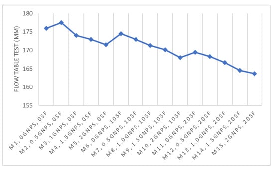
Figure 5.
Flow table test results.
Figure 6 presents the plotted charts of the experimental compressive and flexural strength obtained from different mortar mixes at interval times (3, 7, 14, and 28 days). Each mix involved a specific amount of silica fume and graphene nanoplatelets in accurately assessing each parameter’s contribution to the mortar strength. For instance, Figure 6a shows the relationship between compressive strength and five mortar mixtures incorporating only graphene, which varied from 0% to 2% with an interval of 0.5%. At the same time, Figure 6b,c present the compressive strength evolution using another graphene-based mortar mixture containing 10% and 20% silica fume, respectively. Overall, it can be inferred that the compressive and flexural strength increased with increased curing duration. Furthermore, approximately 85% of the strength enhancement was attained within seven days, which can be attributed to the use of cement I 52.5 R in the current research. This kind of cement is known for its quick setting and high-strength characteristics.
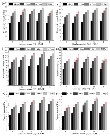
Figure 6.
Experimental strength of the proposed mortar incorporating 0%, 10%, and 20% SF. (a–c) compressive strength, (d–f) flexural strength.
From another point of view, it can be seen that the control mixture (without graphene and silica fume) showed the lowest compressive strength, in which its value was 42.4 MPa, 58.9 MPa, 65.7 MPa, and 70.7 MPa at the age of 3, 7, 14, and 28 days. In addition, the highest compressive strength after 28 days (133.33 MPa) was achieved when the graphene and silica fume content were 1.5% and 20%, respectively. In other words, the compressive strength jumped from 70.7 MPa to 133.33 MPa in the presence of GNPs (1.5%) and SF (20%). This remarkable positive result was attributed to two main reasons. The first reason is the graphene’s efficiency in filling the pores inside the mortar mixture, minimizing the void and tiny cracks. In other words, the excellent dispersion of GNPs inside the mortar matrix would enhance its microstructure and thus increase the compressive strength. This fact is in line with Du, Gao [39], who found that the optimal addition of graphene was 1.5% for the pore refinement. Behind this value, there is no further improvement as the graphene particles face difficulties dispersing inside the mortar matrix.
Meanwhile, the second reason behind the improvement of compressive strength was the pozzolanic activity of silica fume. This is because SF is a very fine amorphous silica whose particle size reaches 0.1 µm [49]. In addition, SF is rich in silica (SiO2), while the cement-based mortar is rich with calcium hydroxide Ca(OH)2 produced during cement hydration [50]. The chemical reaction between (SiO2) and Ca(OH)2 leads to the formation of extra and further calcium silicate hydrate (C-S-H) gels inside the mortar matrix. The C-S-H is the sole main parameter to densify the mortar microstructure. This is consistent with previous research in published academic papers. For example, Zhang, Zhang [51] stated that the size of SF and its high content of amorphous silicon dioxide are the main reasons behind the high pozzolanic activity compared to other pozzolanic materials.
In the same context, flexural strength results tend to have a similar trend of compressive strength. As shown in Figure 6d–f, the flexural strength was enhanced with the increase in curing duration for all mortar mixtures. In addition, adding 1.5% GNPs and 20% SF significantly increased the flexural strength from 9.9 MPa to 20.66 MPa after 28 days, which is double the time of the control mixture. This is because the GNPs play a great role in bridging the cracks and enhancing flexural strength. This fact is also in good agreement with Tong, Fan [52], who found that the flexural strength of ultra-high-performance concrete was improved by more than 50% owing to the presence of both carbon nanofibers and GNPs.
Similarly, the tensile strength of the proposed mortar increased with the increasing age of all mixtures, as shown in Figure 7. For instance, the tensile strength of the proposed mortar incorporating 1% of GNPs and 10% SF was 6.03 MPa, 8.37 MPa, 9.34 MPa, and 10.05 at the age of 3, 7, 14, and 28 days. It was also found that the highest tensile strength was obtained when the GNPs and SF were 1.5% and 20%, respectively. The tensile strength jumped from 6.6 MPa to 14.67 MPa at the age of 28 days, which was attributed to two reasons, as discussed earlier. This fact is also in line with Jiang, Sherif [41], who found that including GNPs raised the tensile strength of the cement-based composites up to 48%.
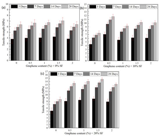
Figure 7.
Experimental tensile strength of the proposed mortar; (a) 0% SF, (b) 10% SF, (c) 20% SF.
The results achieved previously show the potential of utilizing the concrete mix design in 3D concrete applications due to the negligence of the steel fibers and the reinforcement steel bar, which cause difficulties in the extrusion process for some types of 3D concrete printers.
3.2. Prediction Using the RSM Model
Response surface methodology was also used to predict and optimize the compressive, tensile, and flexural strength of ultra-high-performance mortar containing SF and GNPs. For prediction purposes, three second-order polynomial equations were developed to estimate the CS, TS, and FS using three independent variables involving SF, GNPs, and age, as shown in Equations (8)–(10).
The accuracy and reliability of these equations were also evaluated using several mathematical and statistical parameters. For instance, as shown in Figure 8a,c,e, the coefficients of determination (R2) of CS, TS, and FS were greater than 0.9, confirming that the correlation between experimental and predicted results is robust. The proposed equations have the ability to predict mechanical properties with high accuracy. This is in good agreement with Algaifi, Bakar [53], who stated that when the R2 is more significant than 0.7, the predicted and experimental results are relatively similar. Also, Othman, Chong [54] successively developed the RSM model to predict the mechanical properties of concrete containing tire powder and eggshell in which the value of R2 was greater than 0.98. In addition, the statistical error parameters involving SI and MAPE were 0.028 and 0.015, indicating that the model is accurate. Similarly, to assess the models’ suitability, the error distribution (residuals) obtained by the proposed equations was also considered. This is because, according to Hammoudi, Moussaceb [55], a high value of R2 is not enough to consider the equation accurate. As shown in Figure 8b,d,f, the residual errors for CS, TS, and FS were regular. In addition, the majority of the residuals are small and close to zero. Such a fact indicates that the proposed equations can be regarded as accurate and reliable.
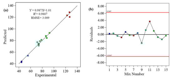
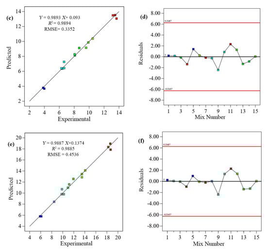
Figure 8.
The correlation and residual error distribution between the experimental and predicted results of (a,b) compressive strength, (c,d) tensile strength, and (e,f) flexural strength.
Meanwhile, the typical probability technique was also used to evaluate the distribution of the data. Indeed, this technique has a strong reputation in the research community for evaluating data distribution [56]. As illustrated in Figure 9a–c, the data were distributed and almost fell on a straight line, indicating that they were almost normally distributed. This is in line with Algaifi, Mustafa Mohamed [57], who developed a mathematical model to predict the mechanical properties of alkali-activated mortar incorporating nano-silica powder, granulated blast-furnace slag (GBFS), and fly ash (FA). The outcome of their research demonstrated the feasibility of their RSM model, as the CS, TS, and FS residuals were normally distributed and presented using a typical probability technique. Similarly, Salah et al. [58] verified the developed RSM model using a typical probability plot in which the data were located along a straight line.
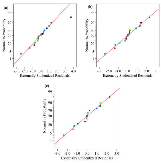
Figure 9.
Typical Plot of Residuals. (a) compressive strength, (b) tensile strength, and (c) flexural strength.
Using the proposed above equations, a contour plot and three-dimensional response surface diagram were also developed to further illustrate the evolution of the compressive, tensile, and flexural strength of the proposed mortar (output) as shown in Figure 10a–c, respectively. These figures are also essential to establish the relationship between the output and independent variables (input) as well as to explain the impact of the independent variables on the mortar strength. The dependent variable was depicted on the vertical (Z-axis), while the independent variables were plotted on the horizontal and vertical (X-axis) axes (Y-axis). The area in red color refers to the maximum strength value, while the blue area indicates the minimum strength. It can be seen that there was a rise in the CS, TS, and FS of the proposed mortar when the silica fume increased up to 20%, and the content of graphene nanoplatelets increased up to 1.5%. Beyond this value, a reduction in the mechanical properties was recorded. This result is in line with the experimental results, which were discussed in detail in Section 3.1.
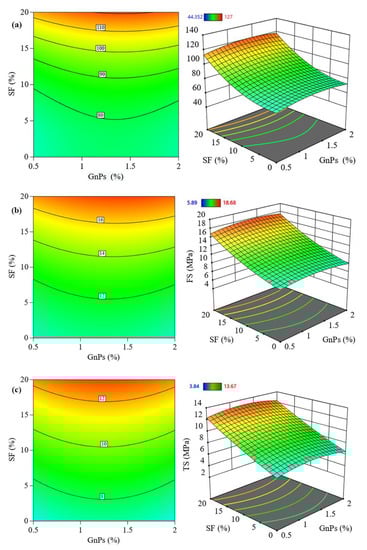
Figure 10.
The predicted evolution of mechanical properties of ultra-high-strength mortar containing graphene and silica fume; (a) compressive strength, (b) flexural strength, and (c) tensile strength.
3.3. Microstructure Analysis
The micrographs were obtained using SEM of the microstructure of concrete samples containing GNPs after 28 days of the Kai Cui process. An inadequate hydration rate causes unreacted objects within the hydrated cement paste, blocking the mixture from reaching its required strength. The GNP quantity used in the mixtures increased the durability and strength of the concrete mixes, resulting in the creation of C-S-H and the chemical interaction within Portlandite (Ca(OH)2) and silica in silica fume in conjunction with GNPs. The microscopy results clearly demonstrated that the strength and dispersion of C-S-H gel in the cemented cement paste had improved. Figure 11 illustrates the internal characteristics of the concrete samples at magnifications of 10 µm (a, c) and 2 µm (b, d), accordingly. GNPs contain many different layers, which improve their toughness and make them excellent for reinforcing composite materials. GNPs have the potential to increase toughness, strength, and resistivity, as previously stated by researchers [59]. Binding the microstructure at the nano level adds more to the reinforcement effect.
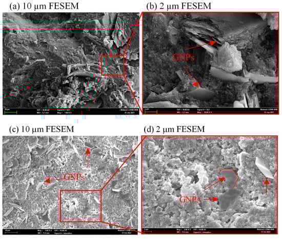
Figure 11.
Image of FESEM test for the concrete specimen containing GNPs; (a,c) magnification of 10 µm and (b,d) magnification of 2 µm.
The EDX test results were utilized to illustrate the impact of GNPs with different concentrations in the concrete at the hydration age of 28th days, as shown in Figure 12. The microstructure characteristic of concrete containing GNPs was deferred with increasing carbon content, which refers to the graphene concentration at 0.5%, 1%, 1.5%, and 2% cement replacement. The wall effect and nanofiller migration effect enrich the ITZ with nanofillers and affect the walls containing GNPs, enhancing the ITZ microstructures [60]. Moreover, when the 0D, 1D, and 2D nanomaterials are combined into the mixture, it can absorb a tremendous amount of water in the composite, enhancing the capacity and decreasing the local water-to-binder content [61].
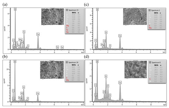
Figure 12.
EDX test Image for the concrete samples that contain graphene nanoplatelets, (a) 0.5% GNPs of 10 µm, (b) 1% GNPs, (c) 1.5% GNPs, and (d) 2% GNPs.
3.4. Numerical Optimization Using the RSM Model
Optimization of the independent variables involving GNPs, SF, and age was numerically obtained using desirability functions that were provided by the RSM model. In the current literature, desirability functions are widely acknowledged as the most effective solution for obtaining the optimal values of the involved parameters. It was calculated based on the maximum value of the proposed mortar’s CS, TS, and FS strength. It is noteworthy that the desirability functions yield multiple solutions, all of which have a dimensionless desirability scale ranging between one and zero. The value of one refers to a desirable strength, while zero indicates a thoroughly undesirable strength. The desirability function (DR) can be defined using Equation (11), where ‘n’ denotes the number of involved variables.
The optimization results of the three independent variables can also be graphically depicted, as shown in Figure 13. It can be seen that the optimal values GNPs and SF were 1.5% and 20%, respectively. Using the optimal value, a maximum strength was recorded in which the CS, TS, and FS were 129.95 MPa, 14.05 MPa, and 19.2 MPa, respectively. This fact is almost in line with our experimental results, which were explained in detail in Section 3.1. It should also be noted that the validation of the optimization process was carried out using three experimental tests. It was found that the error percentage between the experiment and solutions obtained from the desirability function was less than 5%.
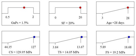
Figure 13.
Optimization of GNPs, SF, and age using the desirability function.
4. Conclusions
The current study set out a daunting objective to develop ultra-high-strength mortar designed for future applications in 3D printing endeavors. Utilizing the unrivaled potential of silica fume and graphene nanoplatelets, the present study aimed to set new ground rules. The predicted findings and the findings from experiments are incorporated to reveal the following prominent conclusions by methodically optimizing the mechanical characteristics, which include compressive, flexural, and tensile strength, using predicted results and experimental data for a theoretical approach:
- The results of the flow table showed a significant decrease in the flow of concrete slurry with the increase in the concentration of GNP. The results confirmed the vital role of nanoparticles in binding the mixture and reducing the amount of water in the mixture.
- Adding both GNPs and SF to the mortar, with a water-to-cement ratio of 0.23 and a cement-to-sand ratio of 1:1, enhanced the compressive strength to an incredible 133.3 MPa, producing a long-lasting impact as well as excellent improvement.
- Beyond a threshold of 1.5% GNPs, mechanical properties began to deteriorate, indicating a possible impairment of hydration and pozzolanic activity due to excessive GNP contents (clustering). As a result, the ideal values of 1.5% GNPs and 20% SF indicated by the desirability function proved to be crucial for the mortar to develop its full potential.
- The tensile and flexural strengths increased by more than 50% when using an optimally measured mixture of 1.5% GNPs and 20% SF due to the exceptional densification of the slurry microstructure and the sealing of irreparable cracks.
- The study focused on decreasing the porousness of the concrete to achieve ultra-high-performance mortar, where the FE-SEM images demonstrated that GNPs could fill the pores in the mortar and connect the cracks to each other.
- The strong confluence of the RSM model and experimental data results demonstrates their remarkable resemblance alongside the error percentages of CS, TS, and FS, all falling below 5%. The above indicates the enormous potential of the suggested three nonlinear equations for accurately predicting the mechanical characteristics of mortar.
- A strong correlation, exceeding 0.97, between anticipated and observed outcomes attests to the model’s unchanging credibility and resilience. The difference between the anticipated and adjusted R2 is 0.2 percent or less, demonstrating the RSM model’s enormous promise for future research. Moreover, statistical error parameters with anticipated and adjusted values less than 0.03 and 0.09, respectively, reinforce the model’s efficiency and correctness, leaving no opportunity for controversy.
Author Contributions
Writing—original draft preparation, H.A.S.; Conceptualization, H.A.S. and H.A.A.; methodology, H.A.A.; software, H.A.A.; validation, A.B.M.A.K. and A.S.; formal analysis, A.A.M. and A.B.M.A.K.; investigation, A.B.M.A.K.; resources, A.S.; data curation, H.A.S.; writing—review and editing, H.A.S. and H.A.A.; supervision, A.A.M.; funding acquisition, A.A.M. All authors have read and agreed to the published version of the manuscript.
Funding
The UKM Centre of Research Management and Instrumentation Management (CRIM), UKM, and the Dana Impak Perdana Grant (DIP-2021-014).
Data Availability Statement
The data presented in this study are available on request from the corresponding author.
Acknowledgments
In obtaining the intended results, the authors would like to thank Universiti Kebangsaan Malaysia (UKM) for financing and supporting this study.
Conflicts of Interest
The authors declare no conflict of interest for the publication of the review paper.
References
- Yang, Y.; Wu, C.; Liu, Z.; Wang, H.; Ren, Q. Mechanical anisotropy of ultra-high performance fibre-reinforced concrete for 3D printing. Cem. Concr. Compos. 2021, 125, 104310. [Google Scholar] [CrossRef]
- Zhang, J.; Wang, J.; Dong, S.; Yu, X.; Han, B. A review of the current progress and application of 3D printed concrete. Compos. Part A Appl. Sci. Manuf. 2019, 125, 105533. [Google Scholar] [CrossRef]
- Buswell, R.A.; De Silva, W.R.L.; Jones, S.Z.; Dirrenberger, J. 3D printing using concrete extrusion: A roadmap for research. Cem. Concr. Res. 2018, 112, 37–49. [Google Scholar] [CrossRef]
- Lee, H.; Kim, J.-H.J.; Moon, J.-H.; Kim, W.-W.; Seo, E.-A. Evaluation of the Mechanical Properties of a 3D-Printed Mortar. Materials 2019, 12, 4104. [Google Scholar] [CrossRef]
- Lin, A.; Tan, Y.K.; Wang, C.-H.; Kua, H.W.; Taylor, H. Utilization of waste materials in a novel mortar–polymer laminar composite to be applied in construction 3D-printing. Compos. Struct. 2020, 253, 112764. [Google Scholar] [CrossRef]
- Long, W.-J.; Tao, J.-L.; Lin, C.; Gu, Y.-C.; Mei, L.; Duan, H.-B.; Xing, F. Rheology and buildability of sustainable cement-based composites containing micro-crystalline cellulose for 3D-printing. J. Clean. Prod. 2019, 239, 118054. [Google Scholar] [CrossRef]
- Martens, P.; Mathot, M.; Bos, F.; Coenders, J. Optimising 3D printed concrete structures using topology optimisation. In High Tech Concrete: Where Technology and Engineering Meet: Proceedings of the 2017 fib Symposium, held in Maastricht, The Netherlands, 12–14 June 2017; Springer: Berlin/Heidelberg, Germany, 2018; pp. 301–309. [Google Scholar] [CrossRef]
- Asprone, D.; Auricchio, F.; Menna, C.; Mercuri, V. 3D printing of reinforced concrete elements: Technology and design approach. Constr. Build. Mater. 2018, 165, 218–231. [Google Scholar] [CrossRef]
- Agustí-Juan, I.; Müller, F.; Hack, N.; Wangler, T.; Habert, G. Potential benefits of digital fabrication for complex structures: Environmental assessment of a robotically fabricated concrete wall. J. Clean. Prod. 2017, 154, 330–340. [Google Scholar] [CrossRef]
- Vantyghem, G.; De Corte, W.; Shakour, E.; Amir, O. 3D printing of a post-tensioned concrete girder designed by topology optimization. Autom. Constr. 2020, 112, 103084. [Google Scholar] [CrossRef]
- Jiang, T.; Cui, K.; Chang, J. Development of low-carbon cement: Carbonation of compounded C2S by β-C2S and γ-C2S. Cem. Concr. Compos. 2023, 139, 105071. [Google Scholar] [CrossRef]
- Cuesta, A.; Ayuela, A.; Aranda, M.A.G. Belite cements and their activation. Cem. Concr. Res. 2021, 140, 106319. [Google Scholar] [CrossRef]
- Wang, L.; Chen, L.; Provis, J.L.; Tsang, D.C.W.; Poon, C.S. Accelerated carbonation of reactive MgO and Portland cement blends under flowing CO2 gas. Cem. Concr. Compos. 2020, 106, 103489. [Google Scholar] [CrossRef]
- Geng, Y.; Wang, Z.; Shen, L.; Zhao, J. Calculating of CO2 emission factors for Chinese cement production based on inorganic carbon and organic carbon. J. Clean. Prod. 2019, 217, 503–509. [Google Scholar] [CrossRef]
- Monteiro, P.J.M.; Miller, S.; Horvath, A. Towards sustainable concrete. Nat. Mater. 2017, 16, 698–699. [Google Scholar] [CrossRef] [PubMed]
- Chen, K.; Xia, J.; Wu, R.; Shen, X.; Chen, J.; Zhao, Y.; Jin, W. An overview on the influence of various parameters on the fabrication and engineering properties of CO2-cured cement-based composites. J. Clean. Prod. 2022, 366, 13296. [Google Scholar] [CrossRef]
- Wang, X.; Zhang, Z.; Li, J.; Wang, W.; Mao, Y.; Song, Z. Quantification of CO2 emission from the preparation and utilization of solid waste-based sulphoaluminate cementitious materials. J. Clean. Prod. 2022, 376, 134054. [Google Scholar] [CrossRef]
- Xu, J.; Li, Y.; Lu, L.; Cheng, X.; Li, L. Strength and durability of marine cement-based mortar modified by colloidal nano-silica with epoxy silane for low CO2 emission. J. Clean. Prod. 2023, 382, 135281. [Google Scholar] [CrossRef]
- Cui, K.; Lu, D.; Jiang, T.; Zhang, J.; Jiang, Z.; Zhang, G.; Chang, J.; Lau, D. Understanding the role of carbon nanotubes in low carbon sulfoaluminate cement-based composite. J. Clean. Prod. 2023, 416, 13260. [Google Scholar] [CrossRef]
- Tahmasebinia, F.; Niemelä, M.; Sepasgozar, S.M.E.; Lai, T.Y.; Su, W.; Reddy, K.R.; Shirowzhan, S.; Sepasgozar, S.; Marroquin, F.A. Three-Dimensional Printing Using Recycled High-Density Polyethylene: Technological Challenges and Future Directions for Construction. Buildings 2018, 8, 165. [Google Scholar] [CrossRef]
- Khan, S.A.; Koç, M.; Al-Ghamdi, S.G. Sustainability assessment, potentials and challenges of 3D printed concrete structures: A systematic review for built environmental applications. J. Clean. Prod. 2021, 303, 127027. [Google Scholar] [CrossRef]
- Wolfs, R.J.M.; Bos, F.P.; Salet, T.A.M. Hardened properties of 3D printed concrete: The influence of process parameters on interlayer adhesion. Cem. Concr. Res. 2019, 119, 132–140. [Google Scholar] [CrossRef]
- Ding, T.; Xiao, J.; Qin, F.; Duan, Z. Mechanical behavior of 3D printed mortar with recycled sand at early ages. Constr. Build. Mater. 2020, 248, 118654. [Google Scholar] [CrossRef]
- Nerella, V.N.; Hempel, S.; Mechtcherine, V. Effects of layer-interface properties on mechanical performance of concrete elements produced by extrusion-based 3D-printing. Constr. Build. Mater. 2019, 205, 586–601. [Google Scholar] [CrossRef]
- Arunothayan, A.R.; Nematollahi, B.; Ranade, R.; Bong, S.H.; Sanjayan, J.G.; Khayat, K.H. Fiber orientation effects on ultra-high performance concrete formed by 3D printing. Cem. Concr. Res. 2021, 143, 106384. [Google Scholar] [CrossRef]
- Shakor, P.; Nejadi, S.; Sutjipto, S.; Paul, G.; Gowripalan, N. Effects of deposition velocity in the presence/absence of E6-glass fibre on extrusion-based 3D printed mortar. Addit. Manuf. 2020, 32, 101069. [Google Scholar] [CrossRef]
- Panda, B.; Lim, J.H.; Tan, M.J. Mechanical properties and deformation behaviour of early age concrete in the context of digital construction. Compos. Part B Eng. 2019, 165, 563–571. [Google Scholar] [CrossRef]
- Sikora, P.; Chung, S.-Y.; Liard, M.; Lootens, D.; Dorn, T.; Kamm, P.H.; Stephan, D.; Elrahman, M.A. The effects of nanosilica on the fresh and hardened properties of 3D printable mortars. Constr. Build. Mater. 2021, 281, 122574. [Google Scholar] [CrossRef]
- An, J.; McInnis, M.; Chung, W.; Nam, B.H. Feasibility of Using Graphene Oxide Nanoflake (GONF) as Additive of Cement Composite. Appl. Sci. 2018, 8, 419. [Google Scholar] [CrossRef]
- Qureshi, T.S.; Panesar, D.K. Nano reinforced cement paste composite with functionalized graphene and pristine graphene nanoplatelets. Compos. Part B Eng. 2020, 197, 108063. [Google Scholar] [CrossRef]
- Cui, K.; Chang, J. Hydration, reinforcing mechanism, and macro performance of multi-layer graphene-modified cement composites. J. Build. Eng. 2022, 57, 104880. [Google Scholar] [CrossRef]
- Priya, T.S.; Mehra, A.; Jain, S.; Kakria, K. Effect of graphene oxide on high-strength concrete induced with rice husk ash: Mechanical and durability performance. Innov. Infrastruct. Solutions 2020, 6, 1–16. [Google Scholar] [CrossRef]
- Amini, K.; Amiri, S.S.; Ghasemi, A.; Mirvalad, S.; Korayem, A.H. Evaluation of the dispersion of metakaolin–graphene oxide hybrid in water and cement pore solution: Can metakaolin really improve the dispersion of graphene oxide in the calcium-rich environment of hydrating cement matrix? RSC Adv. 2021, 11, 18623–18636. [Google Scholar] [CrossRef]
- Zhai, S.; Pang, B.; Liu, G.; Zhang, Y.; Xu, K.; She, W.; Zhang, Y. Investigation on preparation and multifunctionality of reduced graphene oxide cement mortar. Constr. Build. Mater. 2021, 275, 122119. [Google Scholar] [CrossRef]
- Kiamahalleh, M.V.; Gholampour, A.; Tran, D.N.; Ozbakkaloglu, T.; Losic, D. Physiochemical and mechanical properties of reduced graphene oxide–cement mortar composites: Effect of reduced graphene oxide particle size. Constr. Build. Mater. 2020, 250, 118832. [Google Scholar] [CrossRef]
- Sajjad, U.; Sheikh, M.N.; Hadi, M.N. Experimental study of the effect of graphene on properties of ambient-cured slag and fly ash-based geopolymer paste and mortar. Constr. Build. Mater. 2021, 313, 125403. [Google Scholar] [CrossRef]
- Jiang, Z.; Sevim, O.; Ozbulut, O.E. Mechanical properties of graphene nanoplatelets-reinforced concrete prepared with different dispersion techniques. Constr. Build. Mater. 2021, 303, 124472. [Google Scholar] [CrossRef]
- Wang, B.; Jiang, R.; Wu, Z. Investigation of the Mechanical Properties and Microstructure of Graphene Nanoplatelet-Cement Composite. Nanomaterials 2016, 6, 200. [Google Scholar] [CrossRef] [PubMed]
- Du, H.; Gao, H.J.; Pang, S.D. Improvement in concrete resistance against water and chloride ingress by adding graphene nanoplatelet. Cem. Concr. Res. 2016, 83, 114–123. [Google Scholar] [CrossRef]
- Du, H.; Pang, S.D. Enhancement of barrier properties of cement mortar with graphene nanoplatelet. Cem. Concr. Res. 2015, 76, 10–19. [Google Scholar] [CrossRef]
- Jiang, Z.; Sherif, M.M.; Xing, G.; Ozbulut, O.E. Tensile characterization of graphene nanoplatelets (GNP) mortar using acoustic emissions. Mater. Today Commun. 2020, 25, 101433. [Google Scholar] [CrossRef]
- ASTM C33-18; Standard Specification for Concrete Aggregates. ASTM International: West Conshohocken, PA, USA, 2018. Available online: https://www.astm.org/Standards/C33.htm (accessed on 10 March 2023).
- ASTM C230-17; Standard Specification for Flow Table for Use in Tests of Hydraulic Cement. ASTM International: West Conshohocken, PA, USA, 2017. Available online: https://www.astm.org/Standards/C230.htm (accessed on 10 March 2023).
- ASTM C109-09a; Standard Test Method for Compressive Strength of Hydraulic Cement Mortars (Using 2-in. or [50-mm] Cube Specimens). ASTM International: West Conshohocken, PA, USA, 2009. Available online: https://www.astm.org/Standards/C109.htm (accessed on 10 March 2023).
- ASTM C348-21; Standard Test Method for Flexural Strength of Hydraulic-Cement Mortars. ASTM International: West Conshohocken, PA, USA, 2021. Available online: https://www.astm.org/Standards/C348.htm (accessed on 10 March 2023).
- ASTM C496/C496M-21; Standard Test Method for Splitting Tensile Strength of Cylindrical Concrete Specimens. ASTM International: West Conshohocken, PA, USA, 2021. Available online: https://www.astm.org/Standards/C496.htm (accessed on 11 March 2023).
- Al-Fasih, M.Y.; Huseien, G.F.; bin Ibrahim, I.S.; Sam, A.R.; Algaifi, H.A.; Alyousef, R. Synthesis of rubberized alkali-activated concrete: Experimental and numerical evaluation. Constr. Build. Mater. 2021, 303, 124526. [Google Scholar] [CrossRef]
- Mokhtar, N.; Johari, M.A.M.; Tajarudin, H.A.; Al-Gheethi, A.A.; Algaifi, H.A. A sustainable enhancement of bio-cement using immobilised Bacillus sphaericus: Optimization, microstructural properties, and techno-economic analysis for a cleaner production of bio-cementitious mortars. J. Clean. Prod. 2021, 318, 128470. [Google Scholar] [CrossRef]
- Tay, Y.W.D.; Qian, Y.; Tan, M.J. Printability region for 3D concrete printing using slump and slump flow test. Compos. Part B Eng. 2019, 174, 106968. [Google Scholar] [CrossRef]
- Diamond, S.; Sahu, S. Densified silica fume: Particle sizes and dispersion in concrete. Mater. Struct. 2006, 39, 849–859. [Google Scholar] [CrossRef]
- Zhang, Z.; Zhang, B.; Yan, P. Comparative study of effect of raw and densified silica fume in the paste, mortar and concrete. Constr. Build. Mater. 2016, 105, 82–93. [Google Scholar] [CrossRef]
- Tong, T.; Fan, Z.; Liu, Q.; Wang, S.; Tan, S.; Yu, Q. Investigation of the effects of graphene and graphene oxide nanoplatelets on the micro- and macro-properties of cementitious materials. Constr. Build. Mater. 2015, 106, 102–114. [Google Scholar] [CrossRef]
- Algaifi, H.A.; Bakar, S.A.; Alyousef, R.; Sam, A.R.; Alqarni, A.S.; Ibrahim, M.; Shahidan, S.; Ibrahim, M.; Salami, B.A. Machine learning and RSM models for prediction of compressive strength of smart bio-concrete. Smart Struct. Syst. 2021, 28, 535–551. [Google Scholar]
- Othman, R.; Chong, B.W.; Jaya, R.P.; Hasan, M.R.M.; Abdullah, M.M.A.B.; Ibrahim, M.H.W. Evaluation on the rheological and mechanical properties of concrete incorporating eggshell with tire powder. J. Mater. Res. Technol. 2021, 14, 439–451. [Google Scholar] [CrossRef]
- Hammoudi, A.; Moussaceb, K.; Belebchouche, C.; Dahmoune, F. Comparison of artificial neural network (ANN) and response surface methodology (RSM) prediction in compressive strength of recycled concrete aggregates. Constr. Build. Mater. 2019, 209, 425–436. [Google Scholar] [CrossRef]
- Ren, Z.; Liu, Y.; Yuan, L.; Luan, C.; Wang, J.; Cheng, X.; Zhou, Z. Optimizing the content of nano-SiO2, nano-TiO2 and nano-CaCO3 in Portland cement paste by response surface methodology. J. Build. Eng. 2021, 35, 102073. [Google Scholar] [CrossRef]
- Algaifi, H.A.; Mohamed, A.M.; Alsuhaibani, E.; Shahidan, S.; Alrshoudi, F.; Huseien, G.F.; Abu Bakar, S. Optimisation of GBFS, Fly Ash, and Nano-Silica Contents in Alkali-Activated Mortars. Polymers 2021, 13, 2750. [Google Scholar] [CrossRef] [PubMed]
- Salah, H.A.; Mutalib, A.A.; Algaifi, H.A.; Bin Yahya, I.; Yusof, M.A.I.; Sakib, N.; Elsayed, M. Assessment of the Mechanical Properties of High Strength Mortar Incorporating Silica Fume and Graphene Nanoplatelets: Experimental and Mathematical Modeling. Sustainability 2023, 15, 8054. [Google Scholar] [CrossRef]
- Dung, N.T.; Su, M.; Watson, M.; Wang, Y. Effects of using aqueous graphene on behavior and mechanical performance of cement-based composites. Constr. Build. Mater. 2023, 368, 130466. [Google Scholar] [CrossRef]
- Wang, X.; Dong, S.; Ashour, A.; Zhang, W.; Han, B. Effect and mechanisms of nanomaterials on interface between aggregates and cement mortars. Constr. Build. Mater. 2019, 240, 117942. [Google Scholar] [CrossRef]
- Han, B.; Ding, S.; Wang, J.; Ou, J. Nano-Engineered Cementitious Composites: Principles and Practices; Springer: Berlin/Heidelberg, Germany, 2019. [Google Scholar]


Disclaimer/Publisher’s Note: The statements, opinions and data contained in all publications are solely those of the individual author(s) and contributor(s) and not of MDPI and/or the editor(s). MDPI and/or the editor(s) disclaim responsibility for any injury to people or property resulting from any ideas, methods, instructions or products referred to in the content. |
© 2023 by the authors. Licensee MDPI, Basel, Switzerland. This article is an open access article distributed under the terms and conditions of the Creative Commons Attribution (CC BY) license (https://creativecommons.org/licenses/by/4.0/).