Article

Theoretical and Numerical Studies of Elastic Buckling and Load Resistance of a Shuttle-Shaped Double-Restrained Buckling-Restrained Brace

1
School of Civil Engineering, Chongqing Jiaotong University, Chongqing 400074, China
2
State Key Laboratory of Mountain Bridge and Tunnel Engineering, Chongqing Jiaotong University, Chongqing 400074, China
*
Author to whom correspondence should be addressed.
Buildings 2023, 13(8), 1967; https://doi.org/10.3390/buildings13081967
Submission received: 4 July 2023 / Revised: 26 July 2023 / Accepted: 29 July 2023 / Published: 1 August 2023

Abstract

:
A new type of shuttle-shaped double-restrained buckling-restrained brace (SDR-BRB) is proposed, which adopts the form of a shuttle-shaped deformation section similar to its bending moment distribution as the external restraining system. The SDR-BRB has the advantages of superlong size, high load-carrying capacity, and lightweight components, and is suitable for use in large-span spatial structures and bridge structures with an exposed BRB. First, the calculation formula of the elastic buckling load of a pin-ended SDR-BRB is derived based on the equilibrium method, which is verified through the eigenvalue buckling analysis method, and the effects of the main geometric parameters on its elastic buckling behavior are evaluated. The effects of multiple key factors on the load-carrying capacity of the SDR-BRB are then studied by parametric analysis. The results show that the restraining ratio, initial imperfection, and gap have significant effects on the ultimate load-carrying capacity and overall stability of the SDR-BRB, while the effect of the diameter–thickness ratio is relatively small. On this basis, the fitting formula of the critical restraining ratio of the SDR-BRB considering the influences of initial imperfection and gap is proposed and verified by finite element analysis. The research lays a foundation for further research into the elastic–plastic hysteretic behavior and design method of an SDR-BRB.

1. Introduction

A buckling-restrained brace (BRB) is a type of lateral load-resisting member with the dual functions of ordinary brace and metal damper, which can achieve yielding without buckling in axial tensile and compressive states and has a stable load-carrying capacity and excellent hysteretic behavior [1,2,3]. It has been widely used in frame structures, spatial structures, and bridge structures in an earthquake-affected zone and has become an important choice when aiming to realize a seismic design concept based on a structural fuse [4,5,6].
A common BRB is mainly composed of a core member and an external restraining member, which can be divided into reinforced concrete confined BRB, concrete-filled steel tube confined BRB, and all-steel confined BRB according to the materials used in the external restraining member [7,8,9,10,11]. Among these, the all-steel confined BRB avoids the disadvantages of concrete wet work, making for convenient production, transportation, installation, and even reuse after an earthquake. Hence, it has attracted much interest among scholars [12,13,14,15]; for example, Tremblay et al. [16] proposed a square steel tube confined BRB, in which the external restraining member is composed of a square steel tube and a bolted connecting plate. Genna et al. [17] proposed a double-channel steel confined BRB, in which the channel steel needs to be finished and strengthened by stiffening ribs. Zhou et al. [18] proposed a perforated steel-plate assembled BRB based on a design concept that a partial weakening of the core unit is equivalent to a strengthening of other parts. Jia et al. [19] proposed an all-steel fish-bone-shaped assembled BRB, which can maximize the deformation capacity of the fish-bone-shaped core by setting multiple tightening positions within the core. Zhu et al. [20] designed a corrugated-web-connected double-core BRB, which improved the overall flexural stiffness of the external restraining system and the strength of the core at each end.
Recently, the trend in the development of large-scale and complex engineering structures has become increasingly prominent. The range of application of BRBs is constantly expanding, and the trend is towards lower-weight, superlong structures, with high load-carrying capacity [21,22,23]. Therefore, Zhou et al. [24] first proposed a rigid-truss-confined BRB, which improves the load-carrying capacity and hysteretic behavior of the BRB by introducing the truss restraining system. Subsequently, Guo et al. [25] proposed a pretensioned cable-stayed BRB and applied it in a steel structure project in Tangshan, China, with a maximum yield load of 2400 kN and a length of more than 30 m. In addition, Chen et al. [26] designed an inner-stiffened double-tube BRB and conducted a quasi-static hysteretic behavior test on the full-scale specimen with a total length of 15 m. The aforementioned results not only provide an effective solution for tall building structures to replace giant diagonal braces, but also provide a useful reference for the research and development of a superlong BRB. At present, the traditional BRB generally uses a length range of less than 10 m, which is difficult to meet the needs of the design of super-high-rise building structures and large-span spatial structures. The main reason is that the superlong BRB is prone to problems, such as excessive cross-section size, excessive self-weight, uneconomical design, and buckling instability. It cannot meet the requirements of the existing specifications and seriously affects the working performance of the BRB. In addition, the current BRB external restraining system pays special attention to the design of high load-carrying efficiency and lightweight components to meet the actual engineering needs. Thus, a new type of shuttle-shaped double-restrained BRB (SDR-BRB) is proposed. The SDR-BRB forms a double-restrained BRB by adding a shuttle-shaped restrained steel tube outside the double circular steel tube BRB. As the shuttle-shaped external restraining member adopted by the SDR-BRB is consistent with its bending moment distribution, compared with the traditional BRB, the SDR-BRB not only effectively increases the overall design length of the BRB, but also significantly improves the material utilization and load-carrying efficiency of the BRB in structural design. In addition, it also obtains a slender and beautiful appearance effect, which is especially suitable for the design and application of the exposed BRB. The elastic buckling behavior and load resistance of the SDR-BRB are studied through theoretical derivation and numerical analysis. The critical restraining ratio is then determined, which is supposed to provide a reference for the practical application of this new type of BRB.

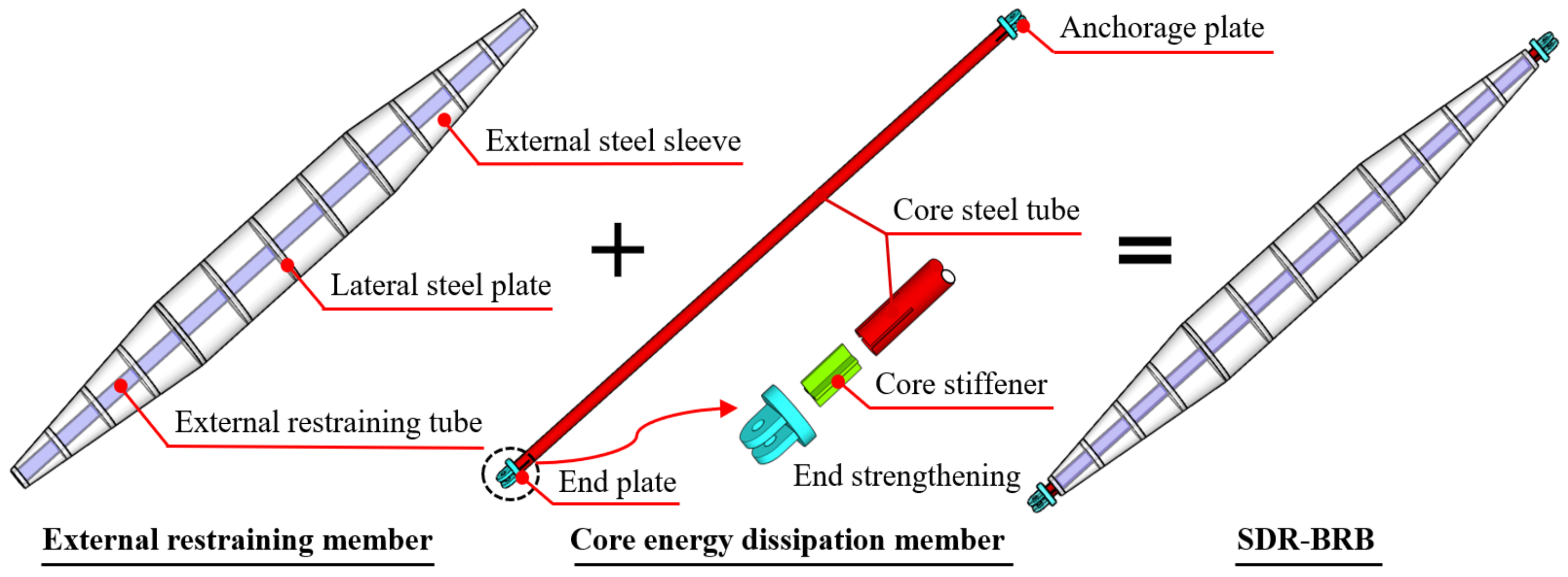
2. Shuttle-Shaped Double-Restrained Buckling-Restrained Brace

As shown in Figure 1, the SDR-BRB consists of a core energy dissipation member and an external restraining member. Among them, the core energy dissipation member is directly subjected to the earthquake axial load and, mainly through the core steel tube, first yields under the earthquake to achieve energy dissipation. The core steel tube generally uses low-yield-point, high-ductility steel and prevents its buckling failure by the external restraining member. The external restraining member can be made of ordinary or high-strength steel. To allow the core to expand slightly under compression and avoid increasing the load-carrying capacity of the member because of the hooping effect, a certain gap is set between it and the core. The external restraining member is composed of the external restraining tube, the lateral steel plate, and the external steel sleeve, which mainly provides lateral elastic support points for the SDR-BRB to reduce its effective calculation length and improve the overall stability of the member. In addition, the core extension construction is also an important part of the SDR-BRB structural design, which is of lower strength and stiffness due to the lack of external restraint. Therefore, to prevent the early failure of the core extension, it is strengthened by reserving slots at the end of the core and welding cross-strengthening ribs to ensure that the core extension does not fail before the brace fails globally while the SDR-BRB completes its energy dissipation requirements.
The SDR-BRB adopts a brace profile with a shuttle-shaped change at both ends of the midspan equal section, which is not only efficient in load carrying and economical in design, but also beautiful in shape. A pin-ended axially loaded member would be subject to lateral flexural deformation when buckling, and its longitudinal distribution of cross-sectional bending moment is large at midspan and small at both ends. Adopting a longitudinal shuttle-shaped member akin to its bending moment distribution can improve the uniformity of the axial stress of a section and the efficiency of material utilization and load resistance, resulting in a more economical design. It is of more significance that the external restraining system adopts a shuttle-shaped deformation section, which increases the overall cross-sectional height and makes a larger lever arm when a lateral flexural deformation of the BRB occurs. Therefore, the overall flexural stiffness is significantly improved, and the structural stress is more reasonable and efficient. The SDR-BRB has the advantages of a superlong size, high load-carrying capacity, and lightweight components. When it is used in large-span spatial structures and bridge structures as exposed lateral force and energy dissipation braces, it can also increase the overall ornamental and aesthetic impact of the structure.

3. Elastic Buckling Behavior of an SDR-BRB

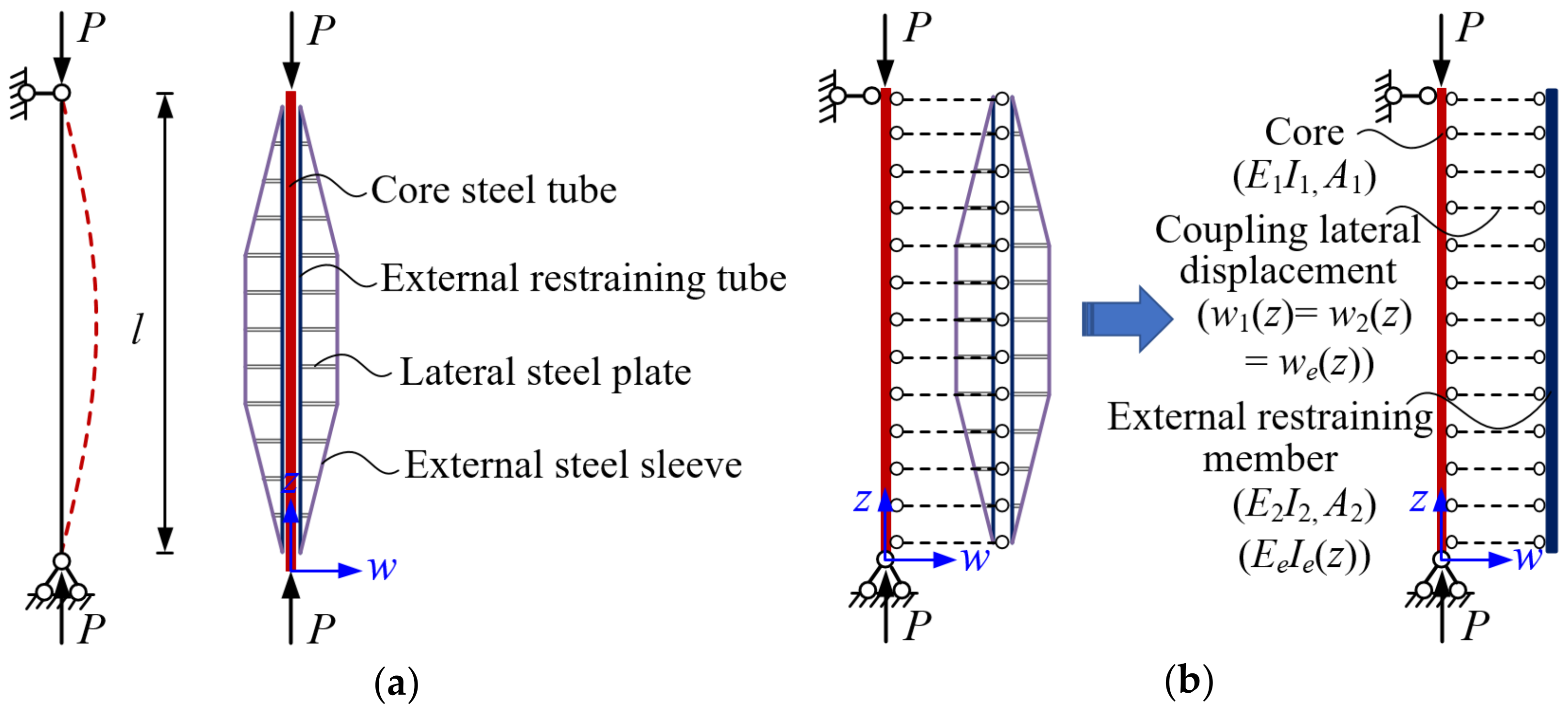
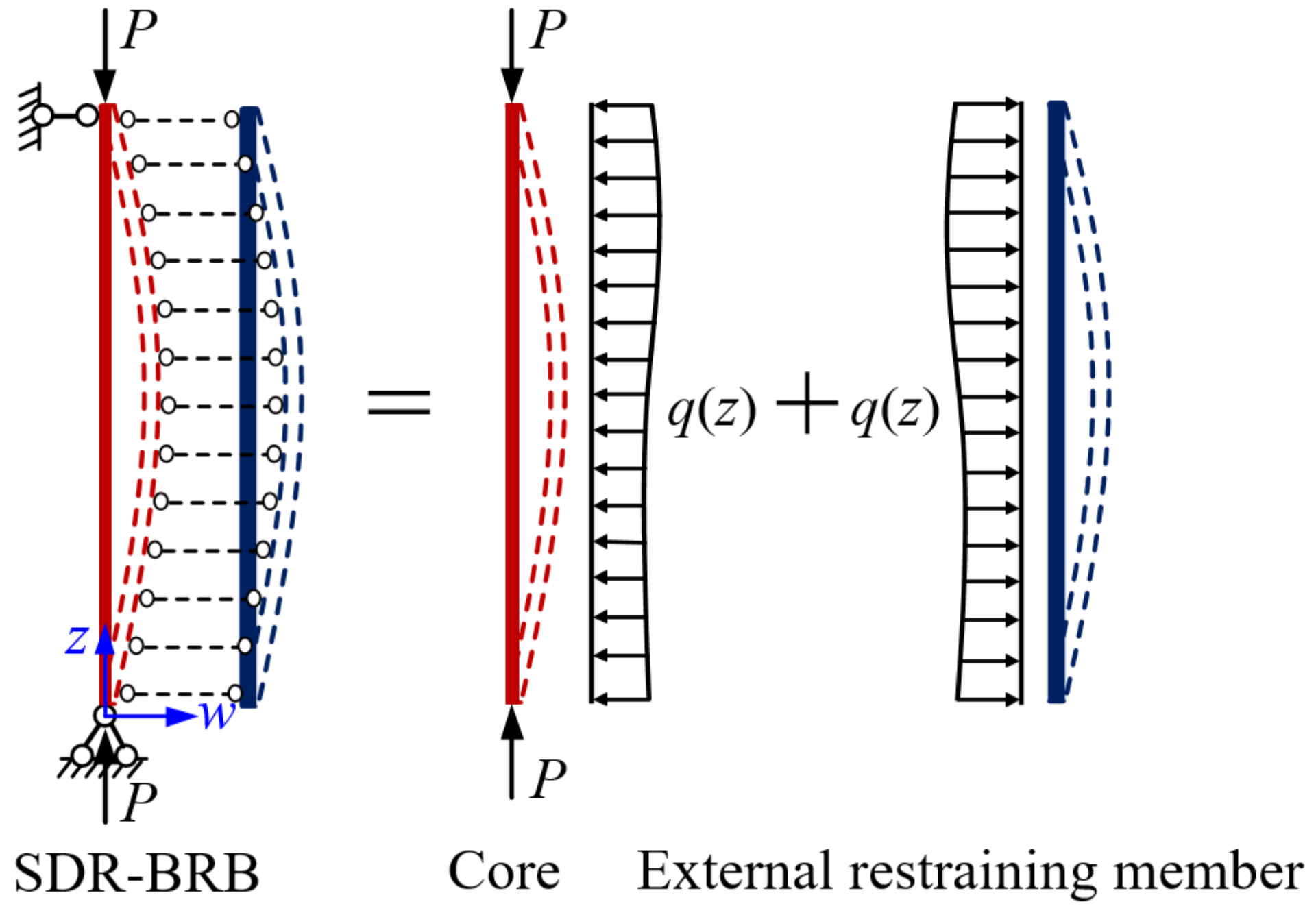
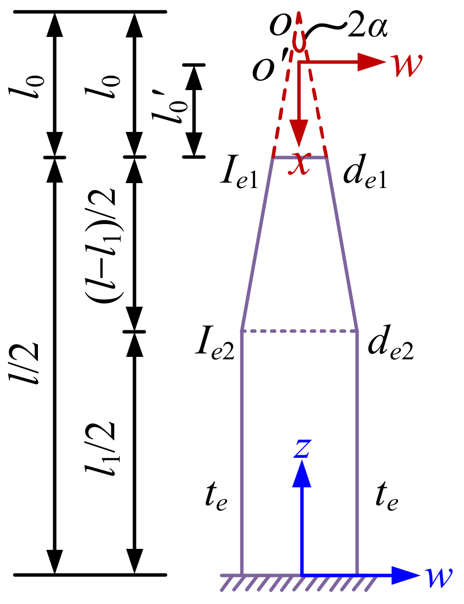
3.1. Simplified Model and Equilibrium Equation

The force mechanism and design method of a BRB have matured: the cross-sectional area of the core can be obtained according to the internal force calculated from the main structure, while the design of the external restraining member usually adopts the core parameter of the restraining ratio as the design basis. The restraining ratio is defined as the ratio of the elastic buckling load of the external restraining member to the full-section yield load of the core, which can be expressed as
ζ = P c r P y
The restraining ratio reflects the restraint ability of the external restraining member to the lateral deformation of the core, and its design goal is to ensure that the BRB does not undergo overall buckling. Equation (1) indicates that the formula for the restraining ratio is closely related to the elastic buckling load. Therefore, it is significant for the subsequent elastic–plastic numerical analysis to study the elastic buckling behavior of the SDR-BRB and establish its elastic buckling load.
The theoretical derivation of the elastic buckling load of the SDR-BRB relies on the following assumptions [27,28,29,30,31]: (1) the friction force between the core and the external restraining member is neglected; (2) the lateral displacements of the core and the external restraining member are identical, while the longitudinal displacements are mutually independent; and (3) the lengths of the core and the external restraining member are identical, and the length of the core extension segment is neglected.
A simplified analytical model of a pin-ended SDR-BRB is shown in Figure 2, where P is the axial load directly applied to the ends of the core; A 1 and A 2 are the cross-sectional areas of the core and the external restraining tube, respectively; E 1 I 1 , E 2 I 2 , and E e I e ( z ) refer to the flexural stiffnesses of the core, the external restraining tube, and the external steel sleeve, respectively. The moments of inertia I 1 and I 2 of the core and the external restraining tube are constant, while the moment of inertia I e ( z ) of the external steel sleeve is a function with respect to the longitudinal coordinate z; w 1 ( z ) , w 2 ( z ) , and w e ( z ) represent the lateral displacements of the core, the external restraining tube, and the external steel sleeve, respectively, which are identical at the same height z, namely, w 1 ( z ) = w 2 ( z ) = w e ( z ) .
As shown in Figure 3, the equilibrium method is used to derive the elastic buckling load of a pin-ended SDR-BRB. Besides the axial load P, the core is also subjected to the lateral distributed load q ( z ) . Its equilibrium equation of bending moment can be written as
P w 1 + 0 z q ( t ) ( z t ) d t = E 1 I 1 d 2 w 1 d z 2
The external restraining member is not subjected to the axial load P, and its equilibrium equation in terms of the bending moment thereon can be expressed as
0 z q ( t ) ( z t ) d t = E 2 I 2 d 2 w 2 d z 2 E e I e ( z ) d 2 w e d z 2
Adding Equations (2) and (3) and substituting w 1 ( z ) = w 2 ( z ) = w e ( z ) = w ( z ) , we obtain
( E 1 I 1 + E 2 I 2 + E e I e ( z ) ) d 2 w d z 2 + P w = 0
where both E 1 I 1 and E 2 I 2 are constant terms, while E e I e ( z ) is a function with respect to the longitudinal coordinate z. Therefore, Equation (4) is solved separately as follows:
E 1 I 1 d 2 w 1 d z 2 + P 1 w 1 = 0 E 2 I 2 d 2 w 2 d z 2 + P 2 w 2 = 0 E e I e ( z ) d 2 w e d z 2 + P e w e = 0
Based on Timoshenko’s classical elasticity theory [32], the elastic buckling load of a pin-ended single-core BRB is considered as the sum of the elastic buckling loads of the core and the external restraining member. Therefore, the following relationship is satisfied:
P c r = P 1 + P 2 + P e
where P 1 , P 2 , and P e denote the elastic buckling loads of the core, the external restraining tube, and the external steel sleeve, respectively.

3.2. Theoretical Solution for Elastic Buckling Load

The cross-sectional moments of inertia of the core and the external restraining tube are constant, and the elastic buckling loads are equal to the respective Euler’s load, which can be written as
P 1 = π 2 E 1 I 1 l 2
P 2 = π 2 E 2 I 2 l 2
As illustrated in Figure 4, due to the external steel sleeve being symmetrical along the z-axis, half of the whole is taken for analysis, where l 0 and l 0 + ( l l 1 ) / 2 are the distances from point O to the end variable section and the midspan equal section, respectively; l 0 + ( l l 1 ) / 2 is the distance from point O to the midspan equal section; l 1 and l are the lengths of the midspan equal section and the full section, respectively; 2 α is the shuttle-shaped angle of the external steel sleeve, satisfying 2 α = 2 arctan ( ( d e 2 d e 1 ) / ( l l 1 ) ) ; I e 1 and I e 2 are the cross-sectional moments of inertia around the w-axis direction for the end variable section and the midspan equal section, respectively; d e 1 and d e 2 denote the diameters of the end variable section and the midspan equal section, respectively; and t e is the thickness of the external steel sleeve.
To facilitate the solution of the subsequent equations, the following normalized parameters are defined: the tapering ratio of the external steel sleeve γ = ( d e 2 d e 1 ) / d e 1 , the thickness–diameter ratio β = t e / d e 1 , and the length ratio λ = l 1 / l , and the following coordinate system conversion is established:
x = l 0 + l / 2 z
The external steel sleeve has a certain thickness, so it cannot intersect at point O , but only at point O . According to the geometry of these similar triangles,
l 0 = l 0 ( 1 2 β ) = ( 1 2 β ) ( l l 1 ) 2 γ
According to Equation (9), the following relationship is established:
d 2 w d z 2 = d ( d w d z ) d z = d ( d w d x d x d z ) d x d x d z = ( 1 ) d ( d w d x ) d x = d 2 w d x 2
The external steel sleeve contains a midspan equal section and an end variable section. When l 0 + ( l l 1 ) / 2 x l 0 + l / 2 ,
E e I e 2 d 2 w e 1 ( x ) d x 2 + P e w e 1 ( x ) = 0
Defining b = P e / E e I e 2 , the following general solution of Equation (12) is obtained:
w e 1 ( x ) = B 1 sin b x + B 2 cos b x
Differentiating Equation (13),
w e 1 ( x ) = b B 1 cos b x b B 2 sin b x
When l 0 x l 0 + ( l l 1 ) / 2 ,
E e I e ( x ) d 2 w e 2 ( x ) d x 2 + P e w e 2 ( x ) = 0
It can be assumed that the cross-sectional moment of inertia of the end variable section is distributed according to the power law of the distance from point O . Therefore, the cross-sectional moment of inertia at any height x can be expressed as
I e ( x ) = I e 2 ( x l 0 + ( l l 1 ) / 2 ) m  
The end variable section is a shuttle-shaped equal-thickness circular tube section, and the exact expression of the cross-sectional moment of inertia is written as
I e ( x ) = π 64 D 4 ( x ) ( D ( x ) 2 t e ) 4  
where D ( x ) and t e are the diameter and the thickness of the external steel sleeve, respectively; D ( x ) 2 x tan α .
As can be seen from Equation (17), the moment of inertia I e ( x ) of the end variable section of the external steel sleeve is a cubic polynomial varying along the axis, and its corresponding equilibrium equation is too complicated to solve. The thickness t e of the external steel sleeve is smaller than its diameter D ( x ) . Therefore, its cross-sectional moment of inertia can be simplified thus:
I e ( x ) = π 8 D 3 ( x ) t e = π t e x 3 tan 3 α
According to Equation (18), the moment of inertia of the end section and the midspan equal section of the external steel sleeve can be obtained as
I e 1 = π t e l 0 3 tan 3 α
I e 2 = π t e ( l 0 + ( l l 1 ) / 2 ) 3 tan 3 α
Substituting Equation (18) into Equation (15) and defining U 2 = P e E e π t e tan 3 α , it can be written as
x 3 d 2 w e 2 ( x ) d x 2 + U 2 w e 2 ( x ) = 0
Equation (21) is a differential equation with variable coefficients. Based on the classical theory of elasticity, the general solution of Equation (21) can be expressed as
w e 2 ( x ) = C 1 x J 1 ( 2 U x ) + C 2 x Y 1 ( 2 U x )
where J 1 ( x ) and Y 1 ( x ) are the first and second type of Bessel function, respectively. The derivation of Equation (22) can be obtained as
w e 2 ( x ) = C 1 J 1 ( 2 U x ) x C 1 U J 0 ( 2 U x ) x + C 2 Y 1 ( 2 U x ) x C 2 U Y 0 ( 2 U x ) x
Substituting the boundary conditions of the end section and midspan section of the external steel sleeve yields
w e 2 ( l 0 ) = 0 w e 1 ( l 0 + l / 2 ) = 0 w e 1 ( l 0 + ( l l 1 ) / 2 ) = w e 2 ( l 0 + ( l l 1 ) / 2 ) w e 1 ( l 0 + ( l l 1 ) / 2 ) = w e 2 ( l 0 + ( l l 1 ) / 2 )
The coefficient matrix of the undetermined coefficients B 1 , B 2 , C 1 , and C 2 can be written as
sin b ( l 0 + ( l l 1 ) / 2 ) cos b ( l 0 + ( l l 1 ) / 2 ) b cos b ( l 0 + l / 2 )     b sin b ( l 0 + l / 2 ) B 1 B 2 = 0
l 0 J 1 ( 2 U l 0 )     l 0 Y 1 ( 2 U l 0 ) J 1 ( 2 U ( l 0 + ( l l 1 ) / 2 ) ) ( l 0 + ( l l 1 ) / 2 ) U J 0 ( 2 U ( l 0 + ( l l 1 ) / 2 ) ) ( l 0 + ( l l 1 ) / 2 ) Y 1 ( 2 U ( l 0 + ( l l 1 ) / 2 ) ) ( l 0 + ( l l 1 ) / 2 ) U Y 0 ( 2 U ( l 0 + ( l l 1 ) / 2 ) ) ( l 0 + ( l l 1 ) / 2 ) C 1 C 2 = 0
The undetermined coefficients B 1 , B 2 , C 1 , and C 2 have nonzero solutions, so the coefficient matrix of Equations (25) and (26) is zero. By solving the above equation, the elastic buckling load expression of the external steel sleeve can be obtained as
P e = K E e I e 2 l 2
where K is the stability coefficient, as given by
K = U ( 1 k 2 ) 1 l 1 / l 2 = U ( 1 k 2 ) 1 λ 2
where U is the root of the derived equation; λ stands for the length ratio of the external steel sleeve; k is the intermediate auxiliary quantity, k 2 m = I e 1 / I e 2 ; and m is the power term of the cross-sectional moment of inertia, m = 3; therefore, the stability coefficient K can be expressed as
K = 4 γ 2 U 2 ( l 0 + ( l l 1 ) / 2 ) ( 1 + γ ) 2 ( 1 λ ) 2
It can be seen from Equation (29) that the stability coefficient K is a function related to the tapering ratio γ and the length ratio λ. Substituting Equation (29) into Equation (27), the elastic buckling load of the external steel sleeve is obtained as
P e = U 2 ( l l 1 ) 2 E e π t e tan 3 α ( 1 λ ) 2 l 2
The condition that the coefficient matrix of Equation (26) is equal to zero can be further expressed as
J 1 ( 2 U l 0 ) Y 1 ( 2 U l 0 + ( l l 1 ) / 2 ) Y 1 ( 2 U l 0 ) J 1 ( 2 U l 0 + ( l l 1 ) / 2 ) J 1 ( 2 U l 0 ) Y 0 ( 2 U l 0 + ( l l 1 ) / 2 ) Y 1 ( 2 U l 0 ) J 0 ( 2 U l 0 + ( l l 1 ) / 2 ) = U l 0 + ( l l 1 ) / 2
By solving Equation (31), U can be determined, and then the stability coefficient K and the elastic buckling load P e can be obtained. However, due to Equation (31) being a complex transcendental equation, it is impossible to attain a unified analytical solution, and only an approximate solution can be obtained by numerical methods.
According to Equations (19) and (20), we obtain
I e 2 I e 1 = π t e ( l 0 + ( l l 1 ) / 2 ) 3 tan 3 α π t e l 0 3 tan 3 α = ( 1 + γ ) 3
The stability coefficient K can be solved by the use of Equations (31) and (32) in Table 1. The numerical fitting method will be adopted to obtain the function expression of the stability coefficient K with sufficient accuracy, and then accurately solve the elastic buckling load of the external steel sleeve.
As shown in Figure 5, the exact solution of the stability coefficient K is in good agreement with the approximate solution, and the maximum discrepancy is 3.7%. The polynomial coefficients of the fitted surface are solved by the least squares method, and the functional relationship between the stability coefficient K, the tapering ratio γ, and the length ratio λ is
K = 9.7681 0.4061 γ 3 1.5143 λ 3 2.4556 γ 2 λ 3.5691 γ λ 2 + 2.6523 γ 2 + 1.5089 λ 2 + 10.7736 γ λ 6.8066 γ 2.4593 × 10 4 λ
Substituting Equations (27) and (33) into Equation (6), the elastic buckling load of the BRB with a shuttle shape at both ends of the midspan equal section is deduced as
P c r = π 2 ( E 1 I 1 + E 2 I 2 + K E e I e 2 ) l 2
According to Equations (32) and (33), when the tapering ratio of the external steel sleeve is γ = 0 , the BRB with a shuttle shape at both ends of the midspan equal section is transformed into the uniform cross-sectional BRB, i.e., I e 1 = I e 2 and K π 2 , which can be written as
P c r , 0 = π 2 ( E 1 I 1 + E 2 I 2 + E e I e 2 ) l 2
When the tapering ratio is γ = 0 , the elastic buckling load expression of the uniform cross-sectional BRB is similar to a pin-ended superimposed beam, and its elastic buckling load is the sum of the Euler loads of the core and the external restraining member, respectively.
According to Equations (34) and (35),
P c r P c r , 0 = E 1 I 1 + E 2 I 2 + K E e I e 2 E 1 I 1 + E 2 I 2 + E e I e 2
Equation (36) represents the ratio of the elastic buckling load P c r of the SDR-BRB to the elastic buckling load P c r , 0 of the uniform cross-sectional BRB, where P c r / P c r , 0 reflects the load-carrying efficiency of the SDR-BRB.

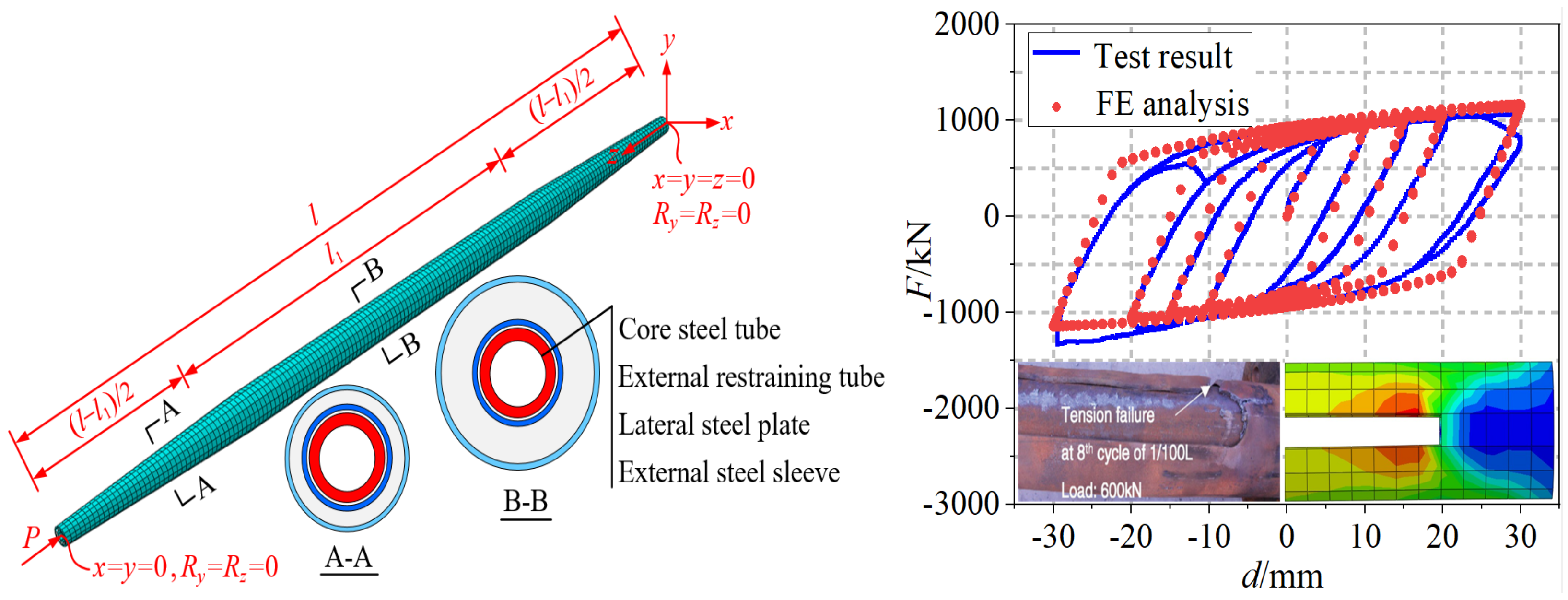
3.3. Establishment and Verification of the Finite Element Model

As shown in Figure 6, the finite element model of the SDR-BRB is established using the commercial software abaqus. All the models are simulated by solid elements, and the element type is an eight-node hexahedral linear reduced integral element (C3D8R), which is suitable for elastic–plastic contact analysis. The material properties of all steels are ideal elasticity with an elastic modulus E of 206 GPa and a Poisson’s ratio υ of 0.3. There is a contact pair between the core and the external restraining tube, which is composed of a master surface and a slave surface. In the present work, the surface of the external restraining tube is taken as the master surface, while the surface of the core is taken as the slave surface. The normal action of the contact surface adopts a hard contact, and the tangential interaction is deemed frictionless. In terms of the loading and boundary condition, the SDR-BRB model is hinged at both ends. Therefore, the translational displacement in x, y, and z directions and the rotation around y and z axes are constrained at the bottom of the core (z = 0). The translational displacement in the x and y directions and the rotation around the y and z axes are constrained at the top of the core (z = L). The finite element model adopts a structured mesh, and the mesh division considers the convergence of the model and the accuracy of the results. The trial method is used for the selection of the element size. The overall structure size is divided into 60 mm grids to minimize the calculation time. In order to test the rationality of the finite element modeling method, the correctness and effectiveness of the SDR-BRB finite element model established by this method are verified by comparing with the existing test results of a tritube BRB [33].
Using the eigenvalue buckling analysis method [34,35,36], the typical overall elastic buckling modes of the pin-ended SDR-BRB finite element model under the action of the axial load P are the single-wave symmetric buckling mode and the double-wave antisymmetric buckling mode, as shown in Figure 7: the elastic buckling mode of the SDR-BRB is the same as that of the shuttle-shaped variable-section steel tube column, although there are significant differences in their force mechanism and basic composition.
According to the value ranges of the tapering ratio γ, the length ratio λ, and the thick-diameter ratio β of the external restraining member, three groups of numerical analysis examples with different calculation lengths are designed (Table 2). Based on this design, the correctness of the theoretical solution of the elastic buckling load of the SDR-BRB is verified, and the effects of the main geometric parameters on its elastic buckling behavior are revealed.
Figure 8 shows the calculated numerical and theoretical solutions of the elastic buckling load of an SDR-BRB: the theoretical results are in good agreement with the numerical results; i.e., the maximum calculation error is 4.4%, and the average error only is 1.7%, which verifies the correctness of the derived calculation formula of the elastic buckling load of the SDR-BRB. In addition, it also reflects that with the increase in the geometric parameters of the external restraining member, P c r / P c r , 0 also increases, in which the tapering ratio γ has the greatest effect, the thickness–diameter ratio β is the second, and the length ratio λ is the smallest. This indicates that increasing the tapering ratio γ can significantly improve the load-carrying efficiency of the SDR-BRB. Therefore, to achieve the high load-carrying efficiency of the SDR-BRB, a larger tapering ratio γ can be preferred while the design and manufacturing requirements are fulfilled.

4. Numerical Analysis of the Load-Carrying Capacity of an SDR-BRB

Existing studies have demonstrated [37,38,39] that the lateral deformation will increase after the overall instability of the BRB, and it will rapidly lose part of its load-carrying capacity until overall failure. Therefore, the overall stability of a BRB is closely related to the load-carrying capacity. Here, the effects of multiple factors, including the restraining ratio, initial geometric imperfection, gap between the core and the external restraining member, and core diameter–thickness ratio, on the load-carrying capacity of an SDR-BRB will be evinced by the monotonic loading of different finite element models. The critical restraining ratio will be further determined to provide a reference for design recommendations of this new type of BRB.
The elastic–plastic load-carrying capacity analysis model of the SDR-BRB is similar to the aforementioned finite element model, but there are differences in material constitutive relationships. The material constitutive model used in monotonic loading is the bilinear kinematic hardening model, which obeys the von Mises yield criterion. Q235 steel with a yield strength of 235 MPa is selected for the core, and Q345 steel with a yield strength of 345 MPa is selected for the external restraining member. The elastic modulus of all steels is 206 GPa, and the tangent modulus of the material after yield is 2% of the elastic modulus. Considering that there is a certain construction error in the actual production, transportation, and installation of the BRB, the initial geometric imperfection that is consistent with its first-order buckling mode is imposed on the finite element model, and the imperfection amplitude is taken as 1/500 of the total length of the BRB, to consider the adverse effect of the initial imperfection. In addition, according to the code for the seismic design of buildings [40], the maximum drift angle of the frame structure is 1/50 under severe earthquakes. Hence, the maximum axial compression strain of the core εmax is 0.02.

4.1. Effect of the Restraining Ratio

The restraining ratio is a key parameter in the design of the BRB, which determines its overall stability. The calculation formula of the elastic buckling load of the SDR-BRB has been derived and verified previously; however, due to the stiffness of the core degrading after entering a full-section yield, the contribution of the core to the overall flexural stiffness of the SDR-BRB can be neglected; then the calculation formula of the restraining ratio of the SDR-BRB can be expressed as
ζ = P 2 + P e P y = π 2 ( E 2 I 2 + K E e I e 2 ) l 2 f y A 1
where f y and A 1 are the yield strength and cross-sectional area of the core, respectively; P y = f y A 1 .
The previous analysis results imply that the tapering ratio γ of the external restraining member has the most significant effect on the elastic buckling behavior of the SDR-BRB. Therefore, the following two groups of elastic–plastic analysis examples with different calculation lengths are designed by changing the tapering ratio γ. The axial load–axial strain curves of the SDR-BRB with different restraining ratios ζ (Figure 9) are obtained by monotonic loading analysis of the two groups of examples (Table 3). The three key loading points (core yield, ultimate state, and final state) corresponding to the typical example SDR-20m-ζ = 1.83 (Figure 9a) are selected to give the von Mises stress distribution and deformation of the core and the external restraining member, respectively, as illustrated in Figure 10.
The horizontal coordinate is the axial compressive strain ε of the core (Figure 9), and the vertical coordinate is the ratio of the axial load P on the core to its full-section yield load Py. The stiffness of the external restraint increases with the increase in the restraining ratio ζ, and the core of the SDR-BRB can reach a full-section yield (Point A in Figure 9a). At this time, the maximum stress on the external restraining member is much less than its yield strength and remains within the elastic range, as shown in Figure 10a. Thereafter, the core enters the hardening stage, and P/Py gradually increases with the increase in axial compressive strain ε. When the restraining ratio ζ is relatively small, the SDR-BRB reaches its ultimate state before the axial compressive strain ε reaches 2% (Point B in Figure 9a), and the midspan region of the external restraining member is the first to yield, as shown in Figure 10b. Subsequently, when the loading continues to ε = 2%, the axial load-carrying capacity of the SDR-BRB decreases rapidly until it reaches its final state (Point C in Figure 9a). At this time, the overall instability of the SDR-BRB occurs, and a single-wave symmetric failure mode akin to the initial imperfection deformation appears, as shown in Figure 10c. When the restraining ratio ζ is relatively large, the external restraining system can provide sufficient restraining stiffness, the core reaches a full-section yield, and the external restraining member remains elastic at ε = 2% throughout the loading process, and the SDR-BRB does not suffer from overall instability failure, such as the cases with SDR-20m-ζ = 2.22 and SDR-30m-ζ = 2.10.
Based on the above finite element elastic–plastic analysis, the failure modes of the SDR-BRB under monotonic load can be divided into the following three categories according to the restraining ratio: (1) When the restraining ratio of the SDR-BRB is relatively small, and the core has not yet reached a full-section yield, the overall instability failure of the SDR-BRB occurs prematurely due to insufficient stiffness of the external restraining member, representing the first type of failure. (2) As the tapering ratio of the external restraining member increases, the flexural stiffness of the section increases, and the restraining ratio of the SDR-BRB also increases. At this time, the core can reach a full-section yield but cannot meet the loading requirement of ε = 2%. The axial compression of the core increases due to its hardening, and the plastic deformation of the external restraining member leads to an overall instability of the SDR-BRB, representing the second type of failure. (3) The last case is when the restraining ratio of the SDR-BRB is large enough for the core to achieve a full-section yield and meet the loading requirement of ε = 2%, and the SDR-BRB does not undergo overall instability upon failure. This third type of the SDR-BRB can not only satisfy the full-section yield of the core, but also permits a certain plastic deformation while retaining some strengthening ability, meaning that it can be considered as a load-carrying type of the BRB that meets the requirements of ductility.

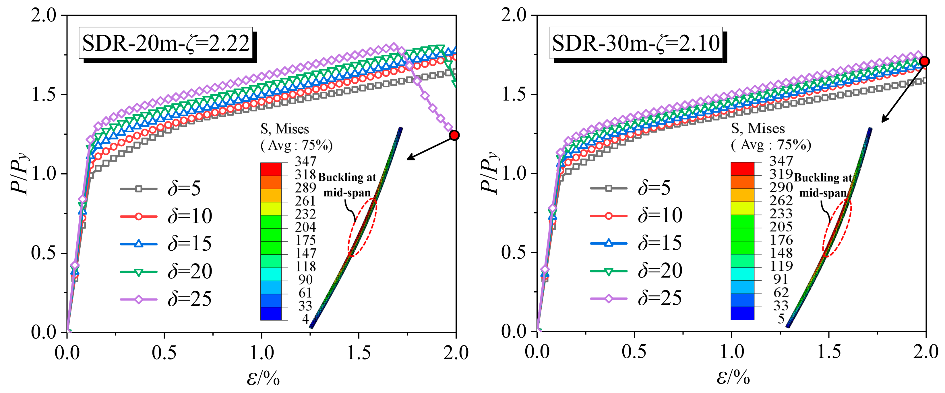
4.2. Effect of the Initial Imperfection

In general, during the fabrication, processing, and installation of the BRB, some damage to the core is inevitable, causing the core to suffer certain initial geometric imperfections before it is loaded. To study the effect of initial geometric imperfections (im) on the load-carrying capacity of the SDR-BRB, SDR-20m-ζ = 2.22 and SDR-30m-ζ = 2.10 are selected to represent the aforementioned load-carrying type of BRB, which can meet the ductility requirements and impose initial geometric imperfections consistent with the first-order buckling mode on them, respectively. The imperfection amplitudes are 1‰, 2‰, 3‰, 4‰, 5‰, and 10‰ of the total length of the BRB.
Figure 11 shows the axial load–axial strain curves of the SDR-BRB with different initial imperfections; the initial imperfections have significant effects on the ultimate load-carrying capacity and overall stability of the SDR-BRB. When the initial imperfection is 3‰, the load-carrying capacity of SDR-20m-ζ = 2.22 and SDR-30m-ζ = 2.10 does not decrease under an axial compressive strain ε of 2%, and the SDR-BRB exhibits good stability at this time. When the initial imperfection is 4‰, the SDR-BRB reaches the ultimate state at ε = 1.6%, after which the axial load-carrying capacity decreases rapidly and the overall instability failure of the SDR-BRB occurs. Furthermore, when the initial imperfections are 5‰ and 10‰, the load-carrying capacity of the SDR-BRB decreases at ε = 1.25% and ε = 0.5%, respectively, and instability failure occurs immediately. Therefore, the more severe the initial imperfection is, the faster the ultimate load-carrying capacity of the SDR-BRB decreases, and the earlier the overall buckling failure occurs.

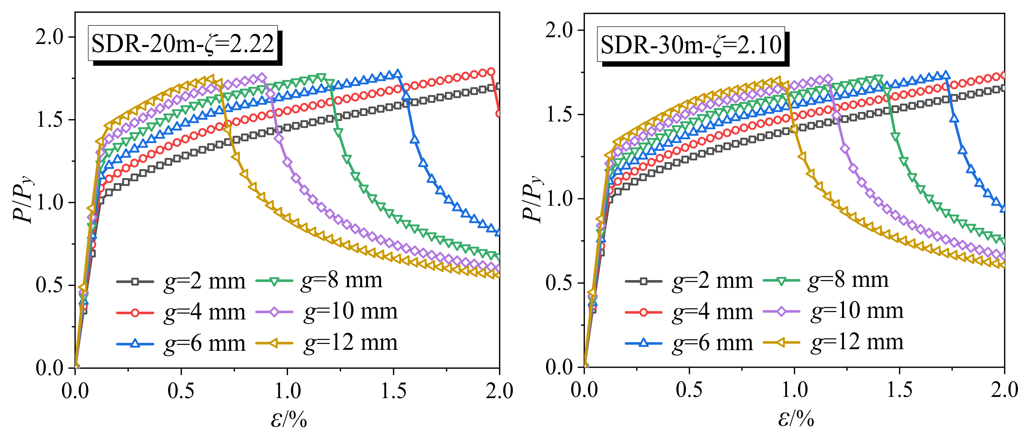
4.3. Effect of the Gap of the Core and the External Restraining Member

The gap between the core and the external restraining member is an important guarantee for the stability of the BRB, and it is also an important parameter for the design of the BRB. The transverse deformation of the core occurs due to the Poisson effect of the material under axial compression. To prevent the extrusion effect of the transverse deformation on the external restraining member, the gap size should be reasonably selected according to the section size of the core. The following examples, SDR-20m-ζ = 2.22 and SDR-30m-ζ = 2.10, are selected for discussion, in which the section size of the core and the external restraining member remains unchanged; only the gap (g) between the core and the external restraining member is changed. During the analysis, g = 2, 4, 6, 8, 10, and 12 mm, respectively, and the initial imperfection amplitude is 1/500 of the total length of the BRB.
Figure 12 shows the axial load–axial strain curves of the SDR-BRB with different gaps; when the gap is within 4 mm, the load-carrying capacity of the SDR-BRB tends to increase with an increasing axial compressive strain ε. As the gap further increases, the ultimate load-carrying capacity of the core is significantly reduced due to the lack of effective restraint after buckling, and the overall instability failure of the SDR-BRB occurs. For example, when the gap is 6 mm, the load-carrying capacity of the examples SDR-20m-ζ = 2.22 and SDR-30m-ζ = 2.10 decreases at ε = 1.5% and ε = 1.75%, respectively, and the buckling-restrained effect is weakened. Thus, setting a reasonable gap value between the core and the external restraining member is an important aspect to improve the load-carrying capacity and stability of the SDR-BRB. In practical engineering applications, the gap between the core and the external restraining member of the SDR-BRB should not be too large.

4.4. Effect of the Core Diameter–Thickness Ratio

The core diameter–thickness ratio is the ratio of the diameter of the core to its thickness, which is the key point of the BRB design control. When the core diameter–thickness ratio is too large, local compression buckling instability may occur even under reasonable gap sizes and restraining ratios, which affects the stable behavior of the BRB. The following examples, SDR-20m-ζ = 2.22 and SDR-30m-ζ = 2.10, are still selected for discussion. The core diameter–thickness ratio (δ) is changed by changing its thickness, and the section size of the external restraining member is adjusted accordingly to maintain the same restraining ratio. During the analysis, δ = 5, 10, 15, 20, and 25, respectively, and the initial imperfection amplitude and the gap between the core and the external restraining member remain unchanged.
Figure 13 displays the axial load–axial strain curves of the SDR-BRB with different diameter–thickness ratios; the diameter–thickness ratio affects the overall load-carrying capacity of the SDR-BRB. When the diameter–thickness ratio is controlled to remain within 20, the ultimate load-carrying capacities of SDR-20m-ζ = 2.22 and SDR-30m-ζ = 2.10 do not decrease under load, and the full-section yield of the core can be achieved without buckling. When the diameter–thickness ratio is 25, the load-carrying capacity curve of the SDR-BRB decreases, while the axial compressive strain ε has not yet reached 2%, and then the midspan buckling instability failure occurs, which indicates that an excessive diameter–thickness ratio is not conducive to the stable behavior of the BRB. Therefore, to ensure that the SDR-BRB has a stable load-carrying capacity, the core diameter–thickness ratio should not exceed 25.

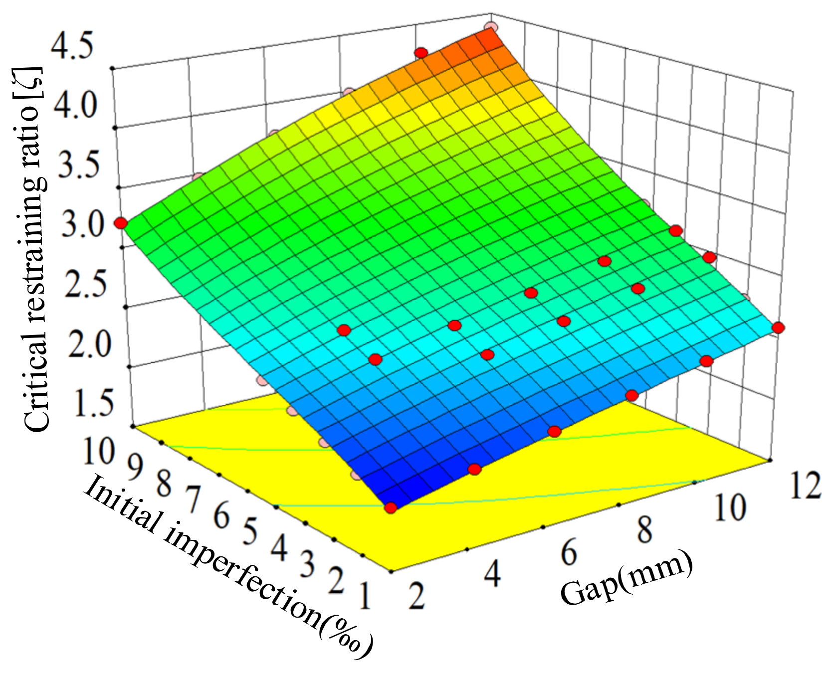
4.5. Determination of the Critical Restraining Ratio

The aforementioned studies show that the greater the restraining ratio, the better the load-carrying capacity and stability of the SDR-BRB; there is a critical restraining ratio, which makes the SDR-BRB (as a load-carrying type of BRB) meet the imposed ductility requirements. However, the critical restraining ratio of the SDR-BRB is not a constant value, but a variable affected by many factors. From the analysis results, the critical restraining ratio is found to be related to the initial imperfection, the gap between the core and the external restraining member, and the core diameter–thickness ratio, which together affect the load-carrying capacity of the SDR-BRB. Among them, the initial imperfection and gap have a significant effect on the critical restraining ratio, while the effect of the diameter–thickness ratio is small. In addition, the comparison shows that the calculation result of SDR-20m is more unfavorable than that of SDR-30m. Therefore, from the perspective of safety and conservative design, the fitting relationship surface of the critical restraining ratio of SDR-BRB with respect to the initial imperfection and the gap is obtained based on the analysis of SDR-20m, as shown in Figure 14.
The red dots represent the sample points of the calculated parameters in Figure 14; the critical restraining ratio of the SDR-BRB increases with the increase in initial imperfection and gap, and the calculated results at the sample points are very close to the fitting surface, indicating that the fitting accuracy of both is high. Using the least squares method to solve the polynomial coefficients of the fitting surface, the fitting formula of the critical restraining ratio of the SDR-BRB can be obtained as
ζ = 1.638 + 7.234 × 10 5 g 3 + 8.733 × 10 4 i m 3 3.056 × 10 4 g 2 i m + 5.29 × 10 4 g i m 2 2.013 × 10 3 g 2 0.015 i m 2 + 4.183 × 10 3 g i m + 0.08 g + 0.185 i m
where ζ is the critical restraining ratio of the SDR-BRB, g denotes the gap between the core and the external restraining member, and im is the initial imperfection.
To verify the correctness and validity of the fitting formula of the SDR-BRB critical restraining ratio, the finite element results of the SDR-20m and SDR-30m critical restraining ratios are compared with the results calculation using the fitting formula.
As shown in Figure 15, compared with the finite element results, the calculation error of the fitting formula of the SDR-BRB critical restraining ratio is small, the calculation errors of both are less than 10%, and most lie within 5%. The error meets the requirements of engineering accuracy, indicating that the fitting formula of the SDR-BRB critical restraining ratio proposed here is reliable and accurate, and can provide a design reference for the practical application of this new type of BRB.

5. Conclusions

A novel SDR-BRB is proposed. Its elastic buckling behavior and elastic–plastic load resistance are studied theoretically and numerically, and the critical restraining ratio of the SDR-BRB is further determined. The main conclusions are drawn as follows:
(1)
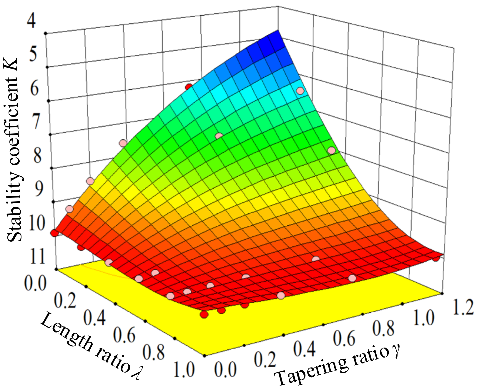
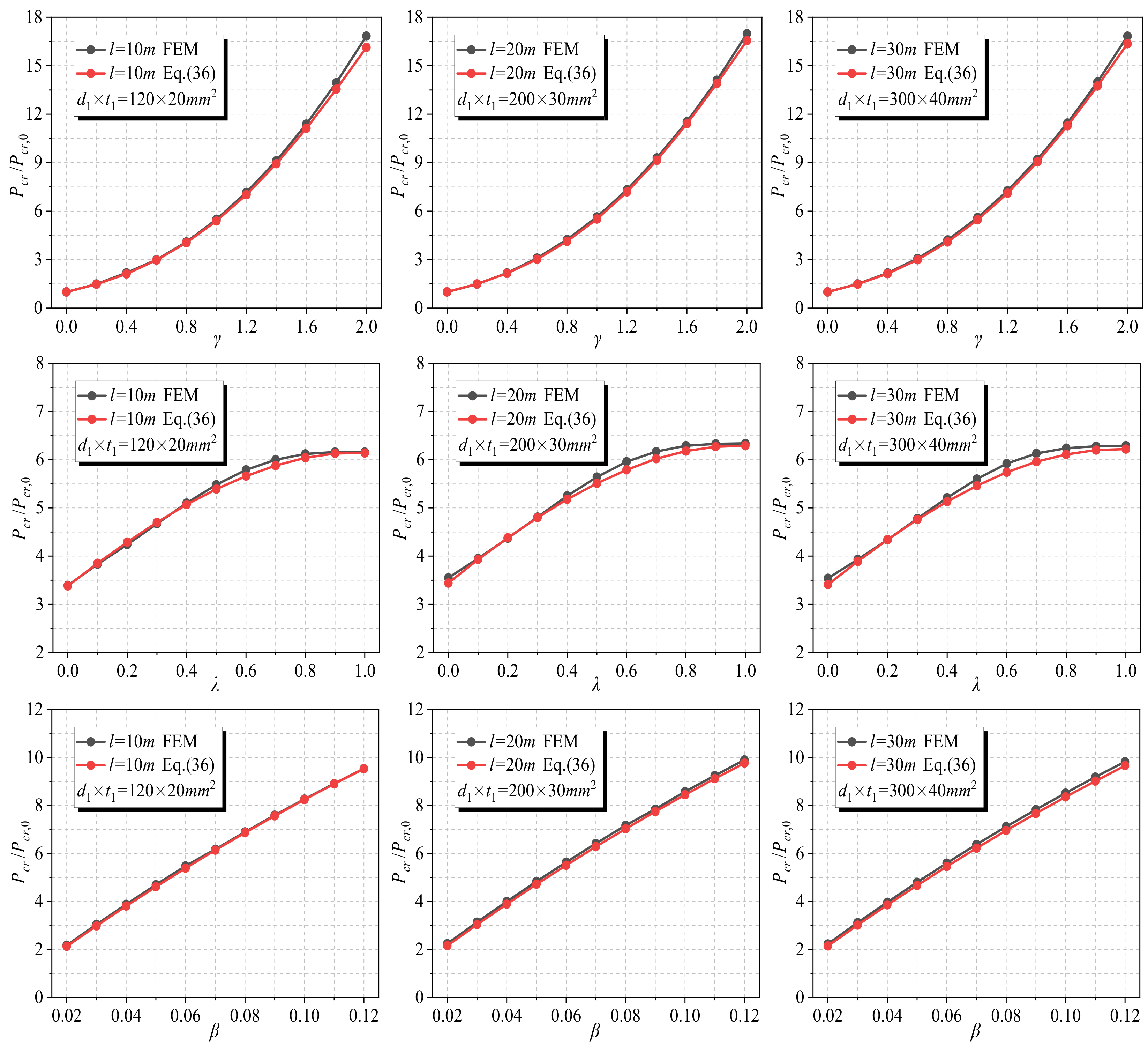
Based on the equilibrium method, the formula for the elastic buckling load of the SDR-BRB is derived and verified by the eigenvalue buckling analysis method. The results show that the theoretical solution is in good agreement with the numerical solution, with discrepancies of less than 5%. As the geometric parameters of the external restraining member increase, the elastic buckling load of the SDR-BRB also increases, among which the tapering ratio γ has the greatest effect. To achieve the high load-carrying efficiency of the SDR-BRB in engineering applications, a larger tapering ratio γ should be preferred.
(2)
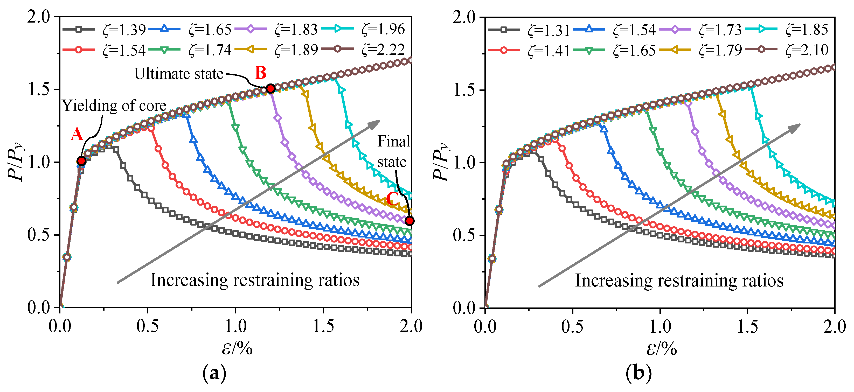
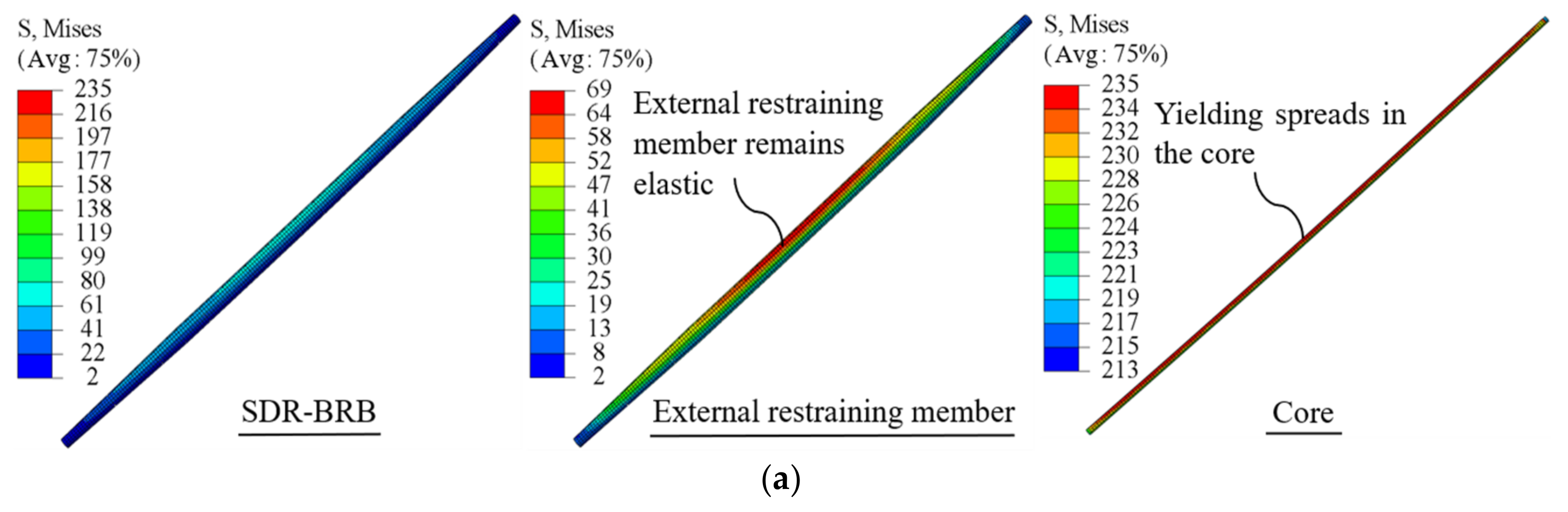
The restraining ratio is an important affecting factor on the overall stability and failure mode of the SDR-BRB. When the restraining ratio is relatively small and the external restraint stiffness is insufficient, the SDR-BRB suffers from a single-wave symmetrical failure mode of midspan buckling instability. When the restraining ratio is relatively large, the SDR-BRB can not only meet the full-section yield of the core, but also have a certain plastic deformation and strengthening ability, allowing it to be considered as a load-carrying type of the BRB that meets the ductility requirements.
(3)
Parametric analysis shows that the initial imperfection and gap have significant effects on the ultimate load-carrying capacity and stability of the SDR-BRB. The larger the initial imperfection and gap, the faster the ultimate load-carrying capacity of SDR-BRB decreases, and the earlier the overall instability failure occurs. In addition, the excessive diameter–thickness ratio is also not conducive to the stable behavior of the SDR-BRB. To ensure that the SDR-BRB has a stable load-carrying capacity, it is recommended that the core diameter–thickness ratio should not exceed 25.
(4)
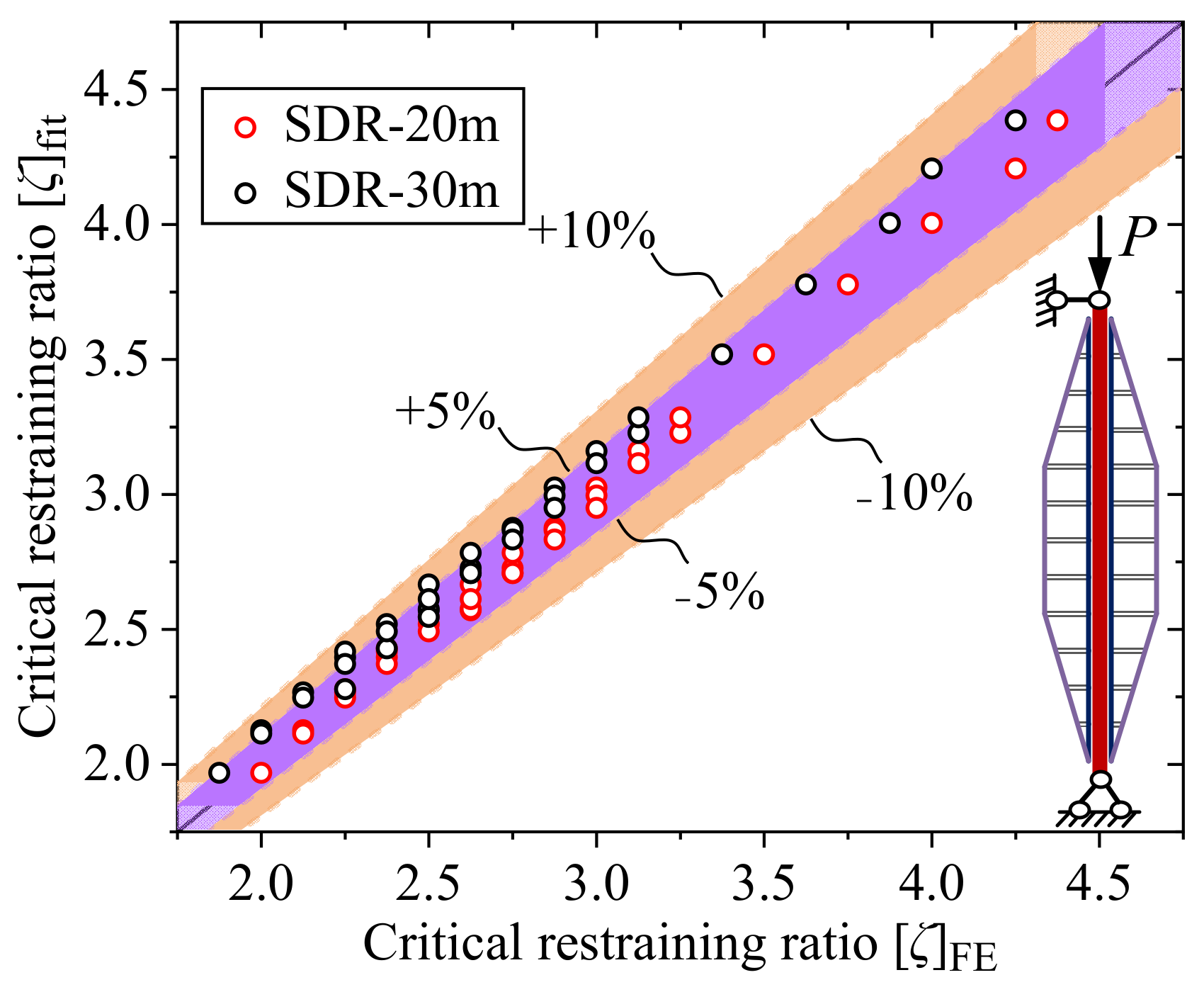
The fitting formula for the critical restraining ratio of SDR-BRB considering the influences of initial imperfection and gap is proposed. Compared with the finite element results, the calculation errors are less than 10%, which shows that the formula has good reliability and high accuracy and can provide a design reference for the practical application of this new type of BRB.
It should be pointed out that the critical restraining ratio ζ determined in this paper has certain limitations, because the effects of important parameters, such as residual stresses, eccentric loads, and friction between the core and the external restraining member, are not fully considered in the finite element model. Therefore, the critical restraining ratio ζ can be used in the preliminary design of the SDR-BRB, and a more accurate restraining ratio lower limit needs to be obtained through more detailed theoretical and experimental studies on the elastic–plastic buckling and elastoplastic hysteresis behavior of the SDR-BRB.

Author Contributions

Conceptualization, J.S. and S.J.; methodology, R.Z.; software, J.S.; validation, J.S., L.X. and S.J.; formal analysis, Y.L.; investigation, J.S.; resources, L.X.; data curation, R.Z.; writing—original draft preparation, J.S.; writing—review and editing, S.J.; visualization, L.X.; supervision, S.J.; project administration, R.Z.; funding acquisition, L.X. All authors have read and agreed to the published version of the manuscript.

Funding

This work was supported by the Guangxi Key Research and Development Program of China (Grant No. Guike AB22036007), the National Natural Science Foundation of China (Grant No. 51978113, 52008064), the Chongqing Natural Science Foundation of China (Grant No. CSTB2022TIAD-KPX0205), and the Postdoctoral Research Program of Chongqing (Grant No. 2022CQBSHTB3082). The authors gratefully acknowledge their financial support.

Data Availability Statement

The data presented in this study are available from the first and corresponding author upon request. The data are not publicly available due to the policy of the data provider.

Conflicts of Interest

The authors declare that they have no known competing financial interests or personal relationships that could have appeared to influence the work reported in this paper.

References

  1. Mirtaheri, M.; Sehat, S.; Nazeryan, M. Improving the Behavior of Buckling Restrained Braces through Obtaining Optimum Steel Core Length. Struct. Eng. Mech. 2018, 65, 401–408. [Google Scholar] [CrossRef]
  2. Sitler, B.; Takeuchi, T.; Matsui, R.; Terashima, M.; Terazawa, Y. Experimental Investigation of a Multistage Buckling-Restrained Brace. Eng. Struct. 2020, 213, 110482. [Google Scholar] [CrossRef]
  3. Bai, J.; Chen, H.; Ma, G.; Duan, L. Development of a Four-Tube-Assembled Buckling-Restrained Brace for Convenient Post-Earthquake Damage Examination and Replacement. J. Build. Eng. 2022, 50, 104209. [Google Scholar] [CrossRef]
  4. Zhou, Y.; Shao, H.; Lui, E.M.; Zhong, G.; Li, Z. Behavior of Elliptical Buckling-Restrained Braces under Cyclic Axial Load. Structures 2023, 48, 331–345. [Google Scholar] [CrossRef]
  5. Castaldo, P.; Tubaldi, E.; Selvi, F.; Gioiella, L. Seismic Performance of an Existing RC Structure Retrofitted with Buckling Restrained Braces. J. Build. Eng. 2021, 33, 101688. [Google Scholar] [CrossRef]
  6. Naghavi, M.; Rahnavard, R.; Thomas, R.J.; Malekinejad, M. Numerical Evaluation of the Hysteretic Behavior of Concentrically Braced Frames and Buckling Restrained Brace Frame Systems. J. Build. Eng. 2019, 22, 415–428. [Google Scholar] [CrossRef]
  7. Chou, C.-C.; Chen, S.-Y. Subassemblage Tests and Finite Element Analyses of Sandwiched Buckling-Restrained Braces. Eng. Struct. 2010, 32, 2108–2121. [Google Scholar] [CrossRef]
  8. Iwata, M.; Murai, M. Buckling-Restrained Brace Using Steel Mortar Planks; Performance Evaluation as a Hysteretic Damper. Earthq. Eng. Struct. Dyn. 2006, 35, 1807–1826. [Google Scholar] [CrossRef]
  9. Usami, T.; Wang, C.-L.; Funayama, J. Developing High-Performance Aluminum Alloy Buckling-Restrained Braces Based on Series of Low-Cycle Fatigue Tests. Earthq. Eng. Struct. Dyn. 2012, 41, 643–661. [Google Scholar] [CrossRef]
  10. Seker, O.; Akbas, B.; Seker, P.T.; Faytarouni, M.; Shen, J.; Mahamid, M. Three-Segment Steel Brace for Seismic Design of Concentrically Braced Frames. J. Constr. Steel Res. 2017, 137, 211–227. [Google Scholar] [CrossRef]
  11. Dehghani, M.; Tremblay, R. Design and Full-Scale Experimental Evaluation of a Seismically Endurant Steel Buckling-Restrained Brace System. Earthq. Eng. Struct. Dyn. 2018, 47, 105–129. [Google Scholar] [CrossRef]
  12. Zhao, J.; Wu, B.; Ou, J. A Novel Type of Angle Steel Buckling-Restrained Brace: Cyclic Behavior and Failure Mechanism. Earthq. Eng. Struct. Dyn. 2011, 40, 1083–1102. [Google Scholar] [CrossRef]
  13. Zhao, J.; Wu, B.; Ou, J. A Practical and Unified Global Stability Design Method of Buckling-Restrained Braces: Discussion on Pinned Connections. J. Constr. Steel Res. 2014, 95, 106–115. [Google Scholar] [CrossRef]
  14. Sun, J.; Pan, P.; Wang, H. Development and Experimental Validation of an Assembled Steel Double-Stage Yield Buckling Restrained Brace. J. Constr. Steel Res. 2018, 145, 330–340. [Google Scholar] [CrossRef]
  15. Wang, C.-L.; Qing, Y.; Wang, J.; Chen, G.; Zeng, B. A New Buckling-Restrained Brace with Gap-Supported Tendon Protection: Experiment and Application. Eng. Struct. 2019, 200, 109688. [Google Scholar] [CrossRef]
  16. Tremblay, R.; Bolduc, P.; Neville, R.; DeVall, R. Seismic Testing and Performance of Buckling-Restrained Bracing Systems. Can. J. Civ. Eng. 2006, 33, 183–198. [Google Scholar] [CrossRef]
  17. Genna, F.; Gelfi, P. Analysis of the Lateral Thrust in Bolted Steel Buckling-Restrained Braces. I: Experimental and Numerical Results. J. Struct. Eng. 2012, 138, 1231–1243. [Google Scholar] [CrossRef]
  18. Zhou, Y.; Gong, C.; Zhao, J.; Zhong, G.; Tian, S. Strong-Axis Stability and Seismic Performance of Perforated Core Plate Buckling-Restrained Braces. Thin-Walled Struct. 2020, 156, 106997. [Google Scholar] [CrossRef]
  19. Jia, L.-J.; Ge, H.; Xiang, P.; Liu, Y. Seismic Performance of Fish-Bone Shaped Buckling-Restrained Braces with Controlled Damage Process. Eng. Struct. 2018, 169, 141–153. [Google Scholar] [CrossRef]
  20. Zhu, B.-L.; Guo, Y.-L.; Zhou, P.; Bradford, M.A.; Pi, Y.-L. Numerical and Experimental Studies of Corrugated-Web-Connected Buckling-Restrained Braces. Eng. Struct. 2017, 134, 107–124. [Google Scholar] [CrossRef]
  21. Bai, J.; Chen, H.; Zhao, J.; Liu, M.; Jin, S. Seismic Design and Subassemblage Tests of Buckling-Restrained Braced RC Frames with Shear Connector Gusset Connections. Eng. Struct. 2021, 234, 112018. [Google Scholar] [CrossRef]
  22. Guo, Y.-L.; Zhu, J.-S.; Zhou, P.; Zhu, B.-L. A New Shuttle-Shaped Buckling-Restrained Brace. Theoretical Study on Buckling Behavior and Load Resistance. Eng. Struct. 2017, 147, 223–241. [Google Scholar] [CrossRef]
  23. Zhu, B.-L.; Guo, Y.-L.; Zhou, P.; Pi, Y.-L. Load-Carrying Performance and Design of BRBs Confined with Longitudinal Shuttle-Shaped-Trusses. J. Constr. Steel Res. 2020, 167, 105954. [Google Scholar] [CrossRef]
  24. Guo, Y.-L.; Zhou, P.; Wang, M.-Z.; Pi, Y.-L.; Bradford, M.A.; Tong, J.-Z. Experimental and Numerical Studies of Hysteretic Response of Triple-Truss-Confined Buckling-Restrained Braces. Eng. Struct. 2017, 148, 157–174. [Google Scholar] [CrossRef]
  25. Guo, Y.-L.; Fu, P.-P.; Zhou, P.; Tong, J.-Z. Elastic Buckling and Load Resistance of a Single Cross-Arm Pre-Tensioned Cable Stayed Buckling-Restrained Brace. Eng. Struct. 2016, 126, 516–530. [Google Scholar] [CrossRef]
  26. Xu, F.; Chen, J.; Shu, K.; Su, M. Cyclic Behaviour of Double-Tube Buckling-Restrained Braces for Boiler Steel Plant Structures. J. Constr. Steel Res. 2018, 150, 556–569. [Google Scholar] [CrossRef] [Green Version]
  27. Kiani, K. Nonlocal and Shear Effects on Column Buckling of Single-Layered Membranes from Stocky Single-Walled Carbon Nanotubes. Compos. Part B Eng. 2015, 79, 535–552. [Google Scholar] [CrossRef]
  28. Kiani, K. Column Buckling of Magnetically Affected Stocky Nanowires Carrying Electric Current. J. Phys. Chem. Solids 2015, 83, 140–151. [Google Scholar] [CrossRef]
  29. Li, S.; Zhang, J.; Zhao, Y. Thermal Post-Buckling of Functionally Graded Material Timoshenko Beams. Appl. Math. Mech. 2006, 27, 803–810. [Google Scholar] [CrossRef]
  30. Mu, B.; Kiani, K. Surface and Shear Effects on Spatial Buckling of Initially Twisted Nanowires. Eng. Anal. Bound. Elem. 2022, 143, 207–218. [Google Scholar] [CrossRef]
  31. Yas, M.H.; Samadi, N. Free Vibrations and Buckling Analysis of Carbon Nanotube-Reinforced Composite Timoshenko Beams on Elastic Foundation. Int. J. Press. Vessels Pip. 2012, 98, 119–128. [Google Scholar] [CrossRef]
  32. Timoshenko, S.; Gere, J. Theory of Elastic Stability; McGraw Hill: New York, NY, USA, 1961. [Google Scholar]
  33. Dongbin, Z.; Xin, N.; Peng, P.; Mengzi, W.; Kailai, D.; Yabin, C. Experimental Study and Finite Element Analysis of a Buckling-Restrained Brace Consisting of Three Steel Tubes with Slotted Holes in the Middle Tube. J. Constr. Steel Res. 2016, 124, 1–11. [Google Scholar] [CrossRef]
  34. Chen, B.; Xu, Q.; Zhu, B.; Yang, Y.; Li, Y. Buckling and Postbuckling Behaviors of Symmetric/Asymmetric Double-Beam Systems. Int. J. Mech. Sci. 2022, 235, 107712. [Google Scholar] [CrossRef]
  35. Kiani, K. Column Buckling of Doubly Parallel Slender Nanowires Carrying Electric Current Acted upon by a Magnetic Field. J. Phys. Chem. Solids 2016, 95, 89–97. [Google Scholar] [CrossRef]
  36. Kiani, K. Axial Buckling Analysis of Vertically Aligned Ensembles of Single-Walled Carbon Nanotubes Using Nonlocal Discrete and Continuous Models. Acta Mech. 2014, 225, 3569–3589. [Google Scholar] [CrossRef]
  37. Hoveidae, N.; Rafezy, B. Overall Buckling Behavior of All-Steel Buckling Restrained Braces. J. Constr. Steel Res. 2012, 79, 151–158. [Google Scholar] [CrossRef]
  38. Pan, W.-H.; Tong, J.-Z. A New Stiffness-Strength-Relationship-Based Design Approach for Global Buckling Prevention of Buckling-Restrained Braces. Adv. Struct. Eng. 2021, 24, 1343–1356. [Google Scholar] [CrossRef]
  39. Momenzadeh, S.; Seker, O.; Faytarouni, M.; Shen, J. Seismic Performance of All-Steel Buckling-Controlled Braces with Various Cross-Sections. J. Constr. Steel Res. 2017, 139, 44–61. [Google Scholar] [CrossRef]
  40. GB 50011-2016; Code for Seismic Design of Buildings. China Plan Press: Beijing, China, 2016; (In Chinese). [CrossRef]
Figure 1. Configuration of the SDR-BRB.
Buildings 13 01967 g001
Figure 2. Simplified analytical model of a pin-ended SDR-BRB: (a) actual model; (b) simplified analytical model.
Buildings 13 01967 g002
Figure 3. Theoretical derivation of the elastic buckling load of an SDR-BRB.
Buildings 13 01967 g003
Figure 4. Coordinate system of an SDR-BRB.
Buildings 13 01967 g004
Figure 5. Fitting surface of the exact and approximate solutions for the stability coefficient K.
Buildings 13 01967 g005
Figure 6. Finite element model of the SDR-BRB.
Buildings 13 01967 g006
Figure 7. Elastic buckling mode of the SDR-BRB: (a) single-wave symmetrical buckling mode; (b) double-wave antisymmetric buckling mode.
Buildings 13 01967 g007
Figure 8. Numerical verification of the elastic buckling load of an SDR-BRB.
Buildings 13 01967 g008
Figure 9. Axial load–axial strain curves of the SDR-BRB with different restraining ratios: (a) SDR-20m-ζ (d1 × t1 = 200 mm × 30 mm); (b) SDR-30m-ζ (d1 × t1 = 300 mm × 40 mm).
Buildings 13 01967 g009
Figure 10. Von Mises stress distribution and deformation of SDR-20m-ζ = 1.83 (unit: MPa): (a) stress distribution and deformation of the SDR-BRB at Point A in Figure 9a, (b) stress distribution and deformation of the SDR-BRB at Point B in Figure 9a, and (c) stress distribution and deformation of the SDR-BRB at Point C in Figure 9a.
Buildings 13 01967 g010aBuildings 13 01967 g010b
Figure 11. Axial load–axial strain curves of the SDR-BRB with different initial imperfections (im).
Buildings 13 01967 g011
Figure 12. Axial load–axial strain curves of the SDR-BRB with different gaps (g).
Buildings 13 01967 g012
Figure 13. Axial load–axial strain curves of the SDR-BRB with different diameter–thickness ratios (δ).
Buildings 13 01967 g013
Figure 14. Fitting surface of the critical restraining ratio of the SDR-BRB.
Buildings 13 01967 g014
Figure 15. Comparison of finite element results of critical restraining ratio and fitting formula.
Buildings 13 01967 g015
Table 1. Exact mathematical solution of the stability coefficient K.
I e 1 / I e 2 γ = I e 2 / I e 1 3 1 λ = l 1 / l
00.20.40.60.81.0
0.11.15445.016.327.849.149.77π2
0.20.71006.147.318.499.399.81π2
0.40.35727.528.389.129.629.84π2
0.60.18568.509.029.469.749.85π2
0.80.07729.239.509.699.819.86π2
1.00π2π2π2π2π2π2
Table 2. Parameters of elastic buckling load verification example (unit: mm).
No.ld1 × t1d2 × t2de1de2γl1λteβ
1-110,000120 × 20140 × 8200200~6000~250000.5120.06
1-210,000120 × 20140 × 820040010~10,0000~1120.06
1-310,000120 × 20140 × 8200400150000.54~240.02~0.12
2-120,000200 × 30240 × 18350350~10500~210,0000.5210.06
2-220,000200 × 30240 × 1835070010~20,0000~1210.06
2-320,000200 × 30240 × 18350700110,0000.57~420.02~0.12
3-130,000300 × 40350 × 23500500~15000~215,0000.5300.06
3-230,000300 × 40350 × 23500100010~30,0000~1300.06
3-330,000300 × 40350 × 235001000115,0000.510~600.02~0.12
Note: d1 × t1 and d2 × t2 are the diameter and thickness of the core and the external restraining tube, respectively, where the gap between the core and the external restraining tube is 2 mm.
Table 3. Calculation parameters for the SDR-BRB load-carrying capacity analysis (unit: mm).
ld1 × t1d2 × t2de1de2γl1λteβζ
20,000200 × 30240 × 18350525~6250.50~0.7810,0000.5210.061.39~2.22
30,000300 × 40350 × 23500760~9000.52~0.8015,0000.5300.061.31~2.10
Disclaimer/Publisher’s Note: The statements, opinions and data contained in all publications are solely those of the individual author(s) and contributor(s) and not of MDPI and/or the editor(s). MDPI and/or the editor(s) disclaim responsibility for any injury to people or property resulting from any ideas, methods, instructions or products referred to in the content.

