Abstract
Unfortunately, most of the previous work studying the fracture toughness of fibrous composites has deliberately ignored bridging the fiber onto the pre-crack/notch surfaces by creating such a crack as a through-thickness crack (TTC). Furthermore, no standard specifications for measuring the fracture toughness of fibrous composites have considered the fiber bridging through the pre-notch. Only a few pieces of research, no more than fingers on one hand, have addressed this problem by creating an actual crack, i.e., a matrix crack (MC) instead of a TTC. The challenge these researchers face is the inability to calculate the fracture toughness directly through the stress intensity factor (SIF) relationship because there is no geometry correction factor equation, f(a/d), for an MC. The main objective of the present work is to calculate f(a/d) and ascertain a relationship between the SIF and crack mouth opening displacement (CMOD) for an MC numerically using 3-D finite element analysis. An experimental program was also conducted to measure the fracture toughness of three types of concrete beams: high-strength concrete (HSC) beams with a TTC, HSC beams with an MC, and fiber-reinforced concrete (FRC) beams with an MC. The results showed that FRC beams with an MC have the highest fracture toughness and, subsequently, the highest resistance to crack growth. The numerical results revealed a suggested relationship between the SIF and CMOD of FRC beams with an MC. This relation was used to predict the fracture toughness of FRC with an MC by the critical value of CMOD measured experimentally.
1. Introduction
Fiber-reinforced concrete (FRC) has gained significant attention in construction due to its ability to enhance the ductility and fracture toughness of high-strength concrete (HSC) [1,2]. Recently Shaaban et al. [3] enhanced the control of multi-level cracking of reinforced concrete beams to increase their toughness and ductility and improve their failure modes by applying the concept of fiber hybridization. The primary method for calculating the stress intensity factor (SIF) is how to simulate concrete fracture behavior. Numerous studies on the behavior of concrete fracture have resulted in the development of numerous applicable concrete fracture models. Using fracture mechanics techniques, concrete cracking resistance is calculated [4,5]. It is considered that the crack in concrete begins to propagate when the SIF approaches the fracture toughness value. Many research attempts were made to evaluate the fracture toughness of concrete with varying constituent mixing ratios [5,6]. Fracture mechanics began to evolve and was used to concrete beams to determine fracture toughness by Kaplan [7]. Several research groups have proposed many fracture models to study the fracture behavior of nonlinear concrete behavior. The following references reviewed these models well [5,8,9]. Based on statistical analysis, Ding [10] suggested a relation between the mid-span deflection and the crack mouth opening displacement (CMOD) of cracked FRC beams. The results showed a linear relation between the mid-span deflection and the CMOD of FRC beams.
On the other hand, Zhang and Li [11] innovated a numerically-solved model based on an integral equation describing bridged cracks proposed by Cox and Marshall [12] to simulate mode I crack propagation in FRC uncracked beams by a fracture mechanics approach. They [11] assumed that the extensometer mounted on the middle section of the beam tensile side could indirectly measure the CMOD which measures the sum of CMOD and the elastic deformation inside the extensometer’s gauge length. They concluded that there is an excellent agreement between model predictions and experimental results regarding load–CMOD curves.
Carpinteri and colleagues [13,14,15] employed the bridge crack model to study the flexural and fracture behavior of FRC beams under static and cyclic loadings. Sallam and colleagues [16,17,18,19,20,21,22] suggested a novel experimental technique for constructing actual cracks and matrix cracks (MCs) in fibrous composites. The main objective of the present work is to obtain the geometry correction factor of MCs using 3-D finite element analysis, i.e., the contour integral technique (CIT) in ABAQUS [23]. Furthermore, the relation between CMOD and SIF was predicted. Then, it follows to incorporate these calculated values into the experimental work to ascertain the actual fracture toughness of rightly-cracked fibrous concrete beams. The influence of fiber position concerning the pre-crack surfaces was also considered. It is worth noting that the present research limitations are the type of tested beam configuration, i.e., the 3PB test with a span-to-depth ratio equal to four and the short fiber type, i.e., end hooked steel fiber: Vf% = 1%, 2%, a/d = 0.1:0.6, fiber positioning ¼, 1/3, ½, and orientation factor 0.33.
2. Numerical Work
The ABAQUS software package [23] is utilized to simulate through-thickness cracked (TTC) and MC beams. The Concrete Damage Plasticity (CDP) model is employed in these simulations. This model was described in the previous work in additional detail [24,25,26,27,28,29]. The compressive stresses and the related inelastic strain relationships were used to determine concrete’s uniaxial behavior in compression. Tensile stresses and the corresponding cracking opening displacement were used to determine the uniaxial behavior of concrete under tension through a bilinear relation.
The CIT was used to investigate the start of failure in the material. In rate-independent quasi-static fracture analysis, the J-integral is typically employed to characterize the energy release associated with crack growth. The material reaction can be connected to the stress intensity component if it is linear. The J-integral is defined as the rate of energy release rate with fracture advancement. The equation gives the energy release rate:
where dA is the surface of the element along a vanishing small tubular surface enclosing the crack tip or crack line, n is the outward normal to dA, and q is the local direction of virtual crack extension. H is given by the equation:
W is the elastic strain energy for an elastic material and the elastic strain energy density plus the plastic dissipation for elastic–plastic or elastic–viscoplastic material. Rice proposed J-integral [30] to characterize the intensity of crack tip singularity. For mode I, the J-integral equals the energy release rate [30] so the stress intensity factor can be calculated using the following equation.
where K is SIF, E′ = E for plane stress, and E′ = E/((1 − v2)) for the plane strain.
The modulus of the elasticity E and Poisson ratio v was 34,000 MPa and 0.2, respectively. Steel fiber properties are elastic–plastic with an ultimate strength equal to 1100 MPa. The C3D8R mesh element type was used for both notched HSC and FRC beams. The crack tip region was surrounded by fine meshing, as shown in Figure 1. The mesh refinement was concentrated around the notch root region since the crack propagation initiates at it is due to the high-stress gradients. The mesh size was minimal at the notch root and gradually increased in size towards the outer directions. Although another high-stress region is in the lower and middle parts of the uncracked beam, the stress diminishes in this region in the notched beam. Therefore, a larger mesh size was used in the present work as stress concentration was observed only at the hook of the steel fiber due to the closure force. Furthermore, the stresses and strains become infinite at the crack tip, varying with the function 1/√r where r represents the radial distance measured from the crack tip. To address this singularity in the strain, it is crucial for the crack faces to be perfectly aligned or coincident. The singularity range in ABAQUS [23] is between 0 to 1. The value was 0.25. The element type around the crack tip was C3D8R. Cohesive contact and separation between the fiber surface and this groove in beams are applied.
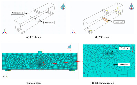
Figure 1.
The details of a simulated beam sample with mesh arrangement.
Consequently, fiber simulation was conducted within the crack surface in the beam by creating grooves in it, taking the shape of the fiber. The fibers were then arranged as in the experimental program. Figure 2 shows the arrangement of fibers in the MC-beam region.
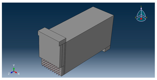
Figure 2.
Fiber arrangement in the MC region.
Mesh sensitivity analysis was performed on the model by using different mesh sizes. A sensitivity analysis was conducted to evaluate the effect of mesh resolution variation on the results. The model’s sensitivity to different mesh densities was assessed by changing the mesh size. Mesh sizes of 0.5, 1, 2, 5, 7, and 10 mm were used. Figure 3 shows the relation both between (crack length to depth ratio) different mesh sizes and their geometry correction factors.
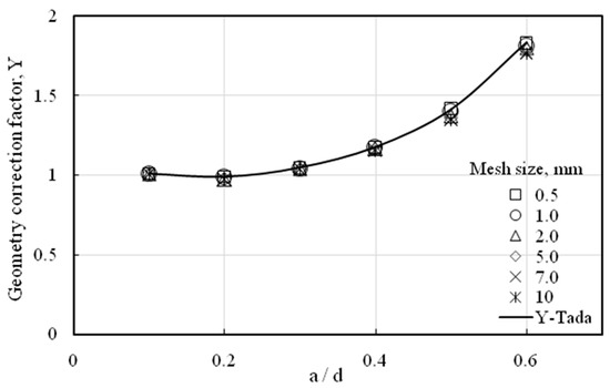
Figure 3.
Effect of mesh size on the geometry correction factor.
SIF was calculated by Equation (3). After obtaining the values of SIF for different beams, the relation between the SIF and stress is used to calculate the geometry correction factor; these values are compared with Tada et al. [31].
where Y is the geometric correction factor for bending beams which is equal to f(a/d).
Also, the geometry correction factor for CMOD was numerically estimated and compared according to Tada et al. [31] as follows:
Figure 4 illustrates the convergence of results between the numerical and Tada relation. Based on the numerical results and their comparison with the Tada relation, applying the same approach to determine the geometry correction factor for matrix crack beams using contour integral is possible.
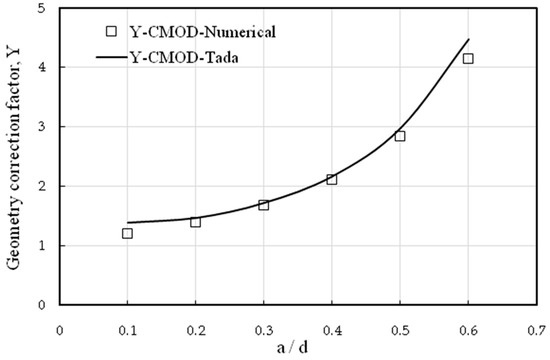
Figure 4.
Comparison between the correction geometry factor for CMOD calculated by Tada and that predicted numerically.
3. Experimental Work
3.1. Materials and Mix Proportions
Three mixes were designed for the experimental program: HSC and two FRCs with fiber volume fraction percentages, Vf%, equal to 1% and 2%. The HSC mix was produced by cement grade N 52.5 and silica fumes as an addition with a content of 10% by the weight of cement content. Also, a superplasticizer was used as a high-range water reducer by 1.1% of the weight of the total cementitious content. The water/cementitious materials ratio (W/CM) was 0.32. The physical properties of the used silica fume and superplasticizer are given in Table 1 and Table 2. The coarse and fine aggregate properties are listed in Table 3. Therefore, FRC mixtures were designed by adding hooked-end steel fibers to the HSC mix by a Vf% equal to 1 and 2%. Hooked-end steel fiber was utilized due to its better flexural performance and strong bond with the cement matrix than crimped or straight SF [1]. Steel fiber was used with a length of 35 mm, a circular cross-section of 0.75 mm in diameter, an ultimate strength of 1100 MPa, and a 7.85 t/m3 density.

Table 1.
Physical properties of the used silica fume.

Table 2.
Properties of the used superplasticizer.

Table 3.
Physical properties of fine and coarse aggregates.
Table 4 shows the quantities of the materials required to produce one cubic meter from each mix. For estimating the mechanical properties of mixtures, the compressive strength was measured by testing cubes with side lengths equal to 150 mm according to BS EN 12390–3:2009 [32]. The indirect tensile strength was measured by testing 300 mm height and 150 mm diameter cylinders according to BS EN 12390–6:2009 [33]. Flexural strength was measured by testing prisms 100 × 100 × 500 mm3 according to BS EN 12390–5:2009 [34]. All specimens of the experimental programs and mechanical properties of mixes were tested after curing in moist air for 56 days. Table 5 shows the fresh and mechanical properties of the mixes of the experimental program.

Table 4.
Materials quantities in kg/m3 to produce 1 m3 for different mixes.

Table 5.
Fresh and mechanical properties for different mixes.
3.2. Experimental Program, Matrix Crack Methodology, and Test Setup
The experimental program consists of 13 patterns of beams divided into three categories. Each pattern consisted of four replicas of specimens to ensure statistical validity. The first category consists of three patterns of smooth beams: one HSC and two FRC beams with a Vf% equal to 1 and 2%. The main concept of this category is to study the flexural strength and toughness of the beams.
The second category comprises seven TTC-HSC and MC-HSC beam patterns. The MC-HSC beams were made from HSC, stitching the pre-crack surfaces with steel fiber, as shown in Figure 5. The MC-HSC pattern beams have three different initial crack-to-depth ratios (a/d) equal to 0.1, 0.3, and 0.5 and two Vf% equal to 1 and 2%, distributed only on the fabricated MC surface. The distributed fibers have different fixation lengths according to their position on the MC; one-third (T), a quarter (Q), and middle (M), as shown in Figure 5. This category is the primary basis of this study. It concerns indicating the effect of fibers’ presence on the crack surface on the enhancement of the fracture properties of the beams.
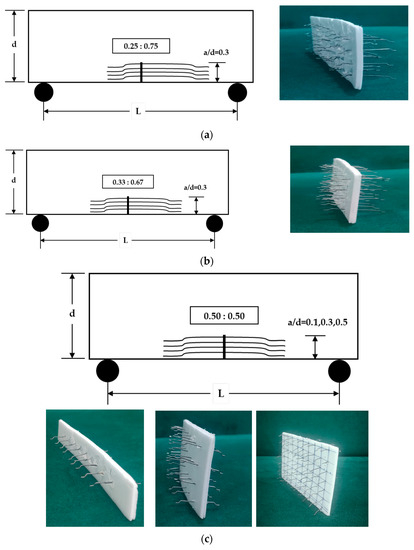
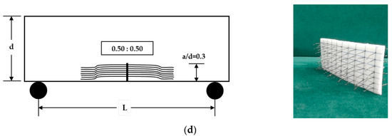
Figure 5.
Distributions and positions of fibers for the MC in the second category with Vf% = 1%: (a) MC-HSC1Q/0.3; (b) MC-HSC1T/0.3; (c) MC-HSC1M/0.1, 0.3, and 0.5; and (d) MC-HSC2M/0.3 with Vf% = 2%.
To create the desired real crack, i.e., an MC, the steel fibers could bridge the crack by crossing over a thin foam plate. SFs were uniformly distributed throughout a 2 mm thick foam plate strip to create an MC within the concrete. The dimensions of the foam plate are equal to the initial crack surface area of the beam. The number of steel fibers allowed to cross the plate was assumed to be one-third of the total numbers representing 1 or 2% of the concrete volume fraction, as shown in Figure 5. Consequently, the orientation efficiency factor for the fiber distribution was estimated to be 0.33, assuming ideal theoretical conditions. In addition, an adhesive material was also used to secure the fibers within the foam and fix the fiber position, middle, one-third, and quarter on the MC. Finally, the manufactured MC was set in two grooves in the middle of the steel mold before casting.
The third category consists of three patterns of MC-FRC beams, with fibers with a Vf% equal to 1 and 2% distributed on the fabricated MC surface and the entire beam. This category aims to verify the fracture toughness calculations for this experimental program and other previous studies of Sallam and co-workers [17,18,19,20,21]. The experimental program is described in detail in Table 6.

Table 6.
The experimental program for different beam categories.
All beams have a constant rectangular cross-section and span length of 150 × 200 × 1000 mm3 with a clear span of 800 mm and a constant span-to-depth ratio (L/d) equal to four. A three-point bending test was applied to all patterns of beams by a universal machine with a capacity of 1000 kN. A load cell with a maximum capacity of 300 kN was used to measure the applied flexural load of the beams. The experiment employed two linear variable differential transformers (LVDTs) with a precision of 0.001. LVDT1 was utilized to measure the deflection at the mid-span of all beams while LVDT2 was employed to measure the CMOD for cracked beams, as shown in Figure 6. All data were acquired using a data acquisition system and collected in a computerized manner.
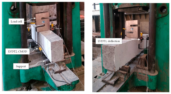
Figure 6.
Details of the test setup and measurement.
4. Results and Discussion
4.1. Numerical Results
Figure 7 shows the numerical values of the geometry correction factor Y obtained by J-Integral for both TTC and MC beams. The results show no significant difference between them up to a/d = 0.4 (small crack length); after that, the value of MC decreases. This can be attributed to the increase in crack surface area and the increase in the number of fibers in the crack surface, consequently leading to an increase in the force magnitude that acts to close the crack; this confirms the effectiveness of the MC approach which takes into consideration the effect of fiber bridging.
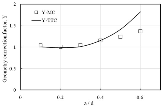
Figure 7.
Numerical geometry correction factor Y values for TTC and MC beams.
Figure 8 shows a comparison between the crack mouth opening displacement CMOD for an MC and TTC at different ratios of a/d by dividing the values of CMOD of MC over the corresponding values of CMOD of TTC. By increasing the a/d ratio, the influence of the MC approach becomes more effective, whereas, a/d equals 0.6 and gives the smallest ratio, as seen in the figure, which confirms that the TTC approach was not reliable in evaluating the realistic fracture toughness if compared with an MC approach which was reliable in obtaining the real fracture toughness because it takes the significant effect of fiber bridging into account. It is clear that CMOD is more sensitive to the presence of fibers across the crack surfaces than the geometry correction factor Y.
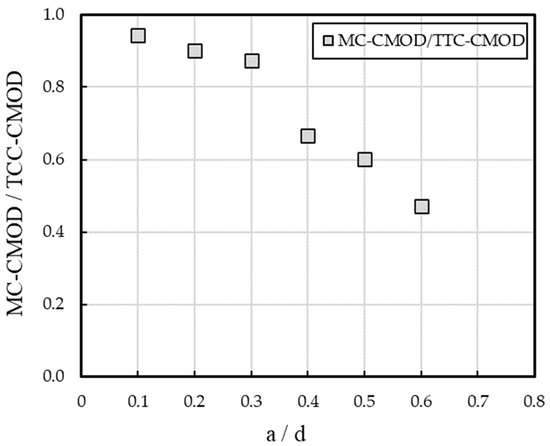
Figure 8.
A comparison between CMOD for MC and TTC.
Figure 9 shows the relation between (CMODxE/(Kx√d) for different ratios of a/d. The values of (CMOD × E/K × √d) were calculated using the value of K, CMOD with E, and beam depth. According to Equation (8), KIC can be estimated from CMOD.
where is a function shown in Figure 9.
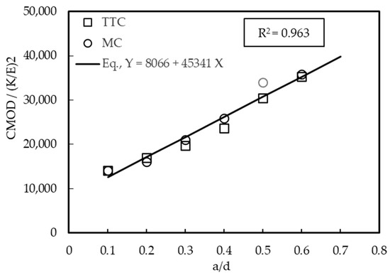
Figure 9.
Relation between CMOD with a stress intensity factor and crack-to-depth ratio (a/d).
The numerical value was used in the previous equation for TTC and MC bridging beams at different crack lengths to estimate the equation shown in Figure 9. Equation (9) is used to predict the fracture toughness (KIC) by measuring the critical value of CMOD (CMODC) as follows:
The figure shows a good relationship between CMOD and a/d, i.e., R2 = 0.962 for linear relation.
4.2. Experimental Results
The fracture surface of beams with different fiber arrangements, namely MC-HSC1Q/0.3, MC-HSC1T/0.3, and MC-HSC1M/0.3, respectively, as illustrated in Figure 10. Due to the excellent bond between the matrix (mortar) and the granular reinforcements (coarse aggregate), the crack grew ahead of the crack tip throw dolomite and mortar. The pull out of the fiber on the surface occurred at the maximum stress. In reality, the fiber orientation in FRC is random but the closing forces of these random fibers can be analyzed in three perpendicular directions. The perpendicular direction to the crack surface is the main effective direction while studying the contribution of fiber bridging during crack propagation. Therefore, knowing the number of fibers normal to a specific cracked section of a structural element is crucial. In steel FRC, a common assumption is that fibers are uniformly distributed [35]. However, the orientation factor, which indicates the efficiency of fiber alignment in three dimensions [2], varies due to factors like the casting method, compaction technique, workability of the concrete mix, and mold dimensions [35,36,37,38,39]. Zandi et al. [40] found that the orientation factor ranges between 1/6 and 1/2. Sallam and Co-workers [17,20,21] found experimentally that the ideal value of the orientation factor ranges from 0.3 to 0.48. These previous findings represent evidence to recommend the value of (1/3) as the best orientation factor in the present work.
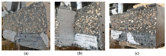
Figure 10.
The fracture surfaces of beams; (a) MC-HSC1Q/0.3, (b) MC-HSC1T/0.3, and (c) MC-HSC1M/0.3.
Figure 11 shows the fracture surface of the following beams: (a) fibers only in the crack surface, (b) fibers entirely in the cracked beam, and (c) fibers entirely on the smooth beam for both Vf% of 1% and 2%. The distribution of hooked-end steel fibers on the fracture surface of beams appears to be satisfactory. This is clear in the uncracked beams, as shown in Figure 11c. Fiber pullout is observed at the fracture surfaces of the beams. The failure observed in this area is classified as a trans-granular fracture due to the excellent bond between the coarse aggregates and mortar at the interface. As a result, there is no contribution from coarse-aggregate bridging or crack deviation to dissipate the energy in these beams effectively.
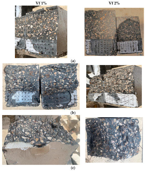
Figure 11.
The fracture surfaces: (a) fibers in the crack surface only, (b) fibers entirely in the cracked specimens, and (c) fibers entirely in the smooth specimens, i.e., without a crack.
Mubaraki et al. [41] proposed a multi-linear curve fitting method to accurately fit various variables’ load–deflection (P-δ) curves. This technique was applied to the curves’ ascending and descending portions for all beams. As shown in Figure 12, the load–deflection data for MC-HSC and MC-FHSC beams represented by symbols were successfully fitted using the multi-linear curve by the solid line.
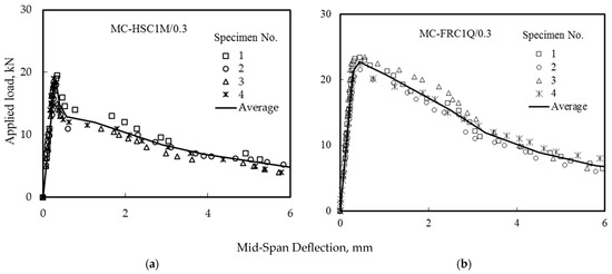
Figure 12.
The average load–deflection curves: (a) MC-HSC1M/0.3 and (b) MC-FRC1Q/0.3.
A comparison between the effect of using two different Vf% of hooked end steel fiber, 1% and 2%, on load deflection and load CMOD for beams with fiber in a crack surface only (MC-HSC) and beams with fiber in full depth (MC-FHSC) was shown in Figure 13. The curves were plotted for beams having a/d equals to 0.3 and 50:50 fiber arrangement.
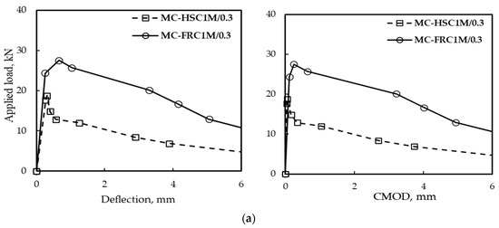
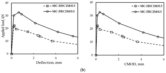
Figure 13.
The effect of fiber content on load deflection and CMOD behavior for a/d = 0.3: (a) Vf% = 1% and (b) Vf% = 2%.
As seen in Figure 13, the fiber in full-depth MC-FRC increases the load at the first crack and at the maximum compared to the MC-HSC-only fiber on the crack surface. Also, the area under the curve for MC-FRC beams was larger than that of MC-HSC beams which means an increase in toughness. On the other hand, increasing fiber content increases the load and the area under the curve. This is in agreement with Othman et al. [42]. In the case of MC-HSC, i.e., no fiber ahead of the crack tip, it causes a sudden drop after the peak load.
4.3. A Comparison between Experimental and Numerical Results
Load–deflection and load–CMOD curves for HSC beams with three different ratios of a/d, 0.1, 0.3, and 0.5 are shown in Figure 14. A comparison between numerical and experimental results was conducted and listed in Table 7. It is clear from Table 7 that the coefficient of variation percentage (CoV%) of the second and third sets are lower than 5% while the first set is lower than 10%, indicating suitable method performance [40,41]. Generally, CoV% < 10 is considered very good, 10–20 is good, 20–30 is acceptable, and CV > 30 is unacceptable. The higher value of CoV% of the first set than those of the second and third sets may be attributed to the small length of the pre-notch-to-beam depth ratio (a/d = 0.1). Therefore, most of the specifications recommended a/d ranged from 0.3 to 0.5 [41]. On the other hand, the error %, i.e., the difference between the predicted values obtained numerically and those measured experimentally of the first and second sets is lower than 2% while the third set is lower than 7%. The higher error % of the third set may be attributed to the higher numbers of fibers simulated as a/d is the higher value, i.e., =0.5.
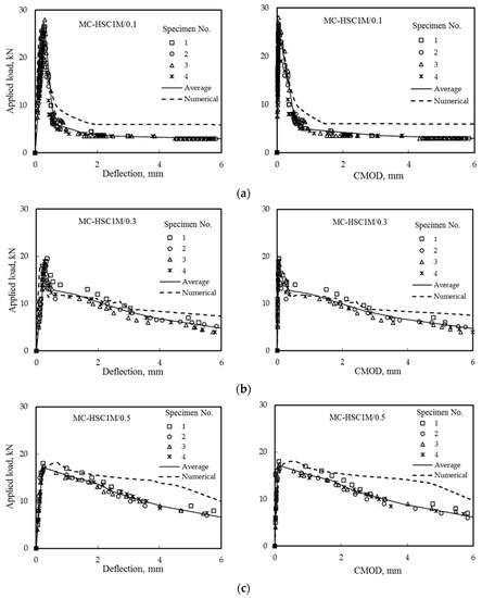
Figure 14.
Effect of (a/d) on load deflection and CMOD; (a) a/d = 0.1, (b) a/d = 0.3, and (c) a/d = 0.5.

Table 7.
Maximum load, deflection, CMOD, slope, ascending, descending, and numerical results for specimens with different a/d.
The fibers in the crack surfaces enhance the properties of HSC due to the fiber’s bridging effect that bridges the crack surfaces. Increasing the crack length with fiber at the surface improves descending. It also increases energy after the maximum load, increasing the ductility and allowing it to undergo more extensive deformation before failure. As seen in Figure 14, the increase in a/d from 0.1 to 0.3 decreased the peak loads by 36.7%, and by increasing the a/d from 0.3 to 0.5 (which produced higher toughness) reduced the peak loads by 9.5%, these results were either listed in Table 7. Figure 14 shows that increasing the a/d ratio resulted in a significant increase in toughness. The corresponding numerical values are close to those measured experimentally, as reported in Table 7. The effect of fiber arrangement on load–deflection and load–CMOD curves for the same a/d equal to 0.3 were shown in Figure 15 and listed in Table 8.
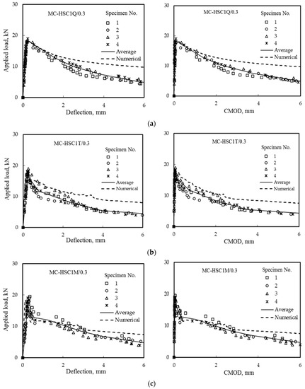
Figure 15.
Effect of fiber arrangement on load deflection and CMOD for the same a/d ratios equal to 0.3: (a) 25:75, (b) 50:50, and (c) 33:67.

Table 8.
Maximum load, deflection, CMOD, slope, ascending, descending, and numerical results for specimens with different fiber arrangements.
Fiber arrangement changed the behavior of the curve after peak load, as seen in Table 8. The numerical results also confirmed this observation. The sudden drop after the peak load was noteworthy and occurred in the case of 50:50 fiber arrangement, unlike the two other cases, namely 25:75 and 33:67, which occurred gradually. The gradual drop after the peak load was more apparent in the case of 25:75 fiber arrangement and also gives higher areas under the curves which exhibited more energy absorption (toughness) till failure.
4.4. Fracture Toughness Calculation
Fracture toughness for MC beams was calculated based on three different methods and listed in Table 9. The first method is an approach recently proposed by Elakhras et al. [17]. The steps of this approach can be summarized as follows:

Table 9.
Value of KIC based on three different methods.
- The energy required to initiate the crack is calculated by the difference in the area under the load–deflection curve between the Un-Crack (UC) beam and the MC beam up to the point where the crack will be initiated (dw);
- The dw value is divided by the crack surface area (dA) to obtain GIC;
- The fracture toughness KIC is then calculated by the following.
The second method uses the geometry correction Y obtained from the present FE results for MC-HSC beams. Finally, the third method uses Equation (9) to estimate KIC for MC beams.
Figure 16 shows the values of KIC using different methods. The relation between KIC depends on Y and CMOD for bridging beams closed for 0.3 and 0.5 at the same fiber content. But the value increased for 0.1 and 0.5 according to the CMOD method. Also, the CMOD and new approach are close in KIC value for MC-FHSC.
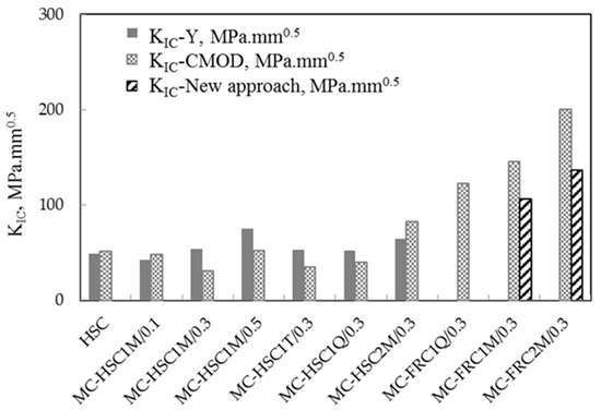
Figure 16.
Fracture toughness for MC beams based on three different methods.
KIC values for beams having different a/d values, 0.1, 0.3, and 0.5, and also different fiber arrangements, are shown in Figure 16 and listed in Table 9. The figure shows that KIC increases with an increasing a/d ratio from 0.1 to 0.5 based on the MC geometry correction factor value according to the first method. KIC for MC-HSC1M/0.1, MC-HSC1M/0.3, and MC-HSC1M/0.5 were 42.2, 54.1, and 75.3 MPa.mm0.5, respectively. On the other hand, beams having a 50:50 fiber arrangement (beam MC-HSC1M/0.3) give the largest values of KIC, which was 54.1 MPa.mm0.5 while the 25:75 fiber arrangement (beam MC-HSC1Q/0.3) gives the smallest value of the KIC of 51.9 MPa.mm0.5. The same observation for FRC concrete, beam MC-FRC1M/0.3 with a 50:50 fiber arrangement, gives KIC equal to 145.4 MPa.mm0.5 compared to the beam MC-FRC1Q/0.3 with a 25:75 fiber arrangement which gives KIC as 122.3 MPa.mm0.5. The effect of Vf% is also shown in Figure 16. Beam MC-HSC2M/0.3 with 2% Vf% provides higher KIC than beam MC-HSC1M/0.3 with 1% Vf%. The same observation occured for beam MC-FRC2M/0.3 which was higher than beam MC-HSC1M3.
5. Conclusions
Based on the current experimental and numerical results and discussion, it can be concluded that:
- The MC beam specimen was an excellent approach to measure the realistic fracture toughness because it considers the effect of fiber bridges on the pre-crack surfaces;
- As expected, increasing fiber content increases the KIC of the tested beams;
- The arrangement of the short hooked-end steel fibers critically affects the fracture toughness of fibrous composites. Based on the results of three arrangements used in this study, i.e., 50:50, 33:67, and 25:75, the best arrangement of such fibers to improve the beam fracture toughness is the symmetry around the crack surface. This may be due to the uniform distribution of closing reactions resulting from such an arrangement;
- A 25:75 fiber arrangement gradually leads to a drop after the peak load and gives higher areas under the curves which exhibited more energy absorption (toughness) until failure;
- Using a 50:50 fiber arrangement gives the largest values of KIC while a 25:75 fiber arrangement gives the smallest (critical) value of the KIC;
- The difference between the predicted values obtained numerically and those correspondingly measured experimentally ranged between 0.31% and 6.07%. Therefore, it can be concluded that there is a good agreement between the experimental and numerical results of the load–deflection and load–CMOD behavior of MC-tested beams.
This study investigated the limited one size of hooked-end steel fiber, i.e., Vf% = 1% and 2%; a/d ranged from 0.1 to 0.6; fiber arrangements = 50:50, 33:67, and 25:75; and the orientation factor was 0.33. Therefore, further investigations, specifically for different short fiber types, geometries, and sizes, should be investigated to predict the geometry correction factor Y as a function of these parameters.
Author Contributions
Conceptualization, M.A.A. and H.E.-D.M.S.; methodology, M.A.A., A.A.E., M.M. and H.E.-D.M.S.; software, M.A.A. and M.M.; validation, R.M.R. and H.E.-D.M.S.; investigation, M.A.A., A.A.E. and M.M.; data curation, M.A.A.; writing—original draft preparation, M.A.A.; writing—review and editing, A.A.E., R.M.R. and H.E.-D.M.S.; visualization, M.A.A., A.A.E., R.M.R. and H.E.-D.M.S.; supervision, A.A.E., M.M. and H.E.-D.M.S.; project administration, H.E.-D.M.S. All authors have read and agreed to the published version of the manuscript.
Funding
This research received no external funding.
Data Availability Statement
All data generated or analyzed during this study are included in this published article.
Conflicts of Interest
The authors declare no conflict of interest.
References
- ACI 544.4R-18; Guide for Design with Fiber-Reinforced Concrete. American Concrete Institute: Farmington Hills, MI, USA, 2018; pp. 1–33.
- Naaman, A.E. Fiber Reinforced Cement and Concrete Composites, 1st ed.; Techno-Press 3000: Sarasota, FL, USA, 2018. [Google Scholar]
- Shaaban, I.G.; Said, M.; Khan, S.U.; Eissa, M.; Elrashidy, K. Experimental and theoretical behaviour of reinforced concrete beams containing hybrid fibres. Structures 2021, 32, 2143–2160. [Google Scholar] [CrossRef]
- Kachanov, M. In Fracture Toughness and Fracture Energy of Concrete; Elsevier: Amsterdam, The Netherlands, 1985. [Google Scholar]
- Shah, S.P.; Swartz, S.E.; Ouyang, C. Fracture Mechanics of Concrete: Applications of Fracture Mechanics to Concrete, Rock and Other Quasi-Brittle Materials; John Wiley & Sons: Hoboken, NJ, USA, 1995. [Google Scholar]
- Shah, S.P. Measurement and modeling of fracture processes in concrete. Mater. Sci. Concr. 1992, 243, III. [Google Scholar]
- Kaplan, M.F. Crack propagation and the fracture of concrete. J. Proc. 1961, 58, 591–610. [Google Scholar]
- Xu, S.; Reinhardt, H.W. A simplified method for determining double-K fracture parameters for three-point bending tests. Int. J. Fract. 2000, 104, 181–209. [Google Scholar] [CrossRef]
- Kumar, S.; Barai, S.V. Concrete Fracture Models and Applications; Springer-Verlag: Berlin/Heidelberg, Germany, 2011; 262p. [Google Scholar] [CrossRef]
- Ding, Y. Investigations into the relationship between deflection and crack mouth opening displacement of SFRC beam. Constr. Build. Mater. 2011, 25, 2432–2440. [Google Scholar] [CrossRef]
- Zhang, J.; Li, V.C. Simulation of crack propagation in fiber-reinforced concrete by fracture mechanics. Cem. Concr. Res. 2004, 34, 333–339. [Google Scholar] [CrossRef]
- Cox, B.N.; Marshall, D.B. Stable and unstable solutions for bridged cracks in various specimens. Acta Metall. Mater. 1991, 39, 579–589. [Google Scholar] [CrossRef]
- Accornero, F.; Rubino, A.; Carpinteri, A. A fracture mechanics approach to the design of hybrid-reinforced concrete beams. Eng. Fract. Mech. 2022, 275, 108821. [Google Scholar] [CrossRef]
- Accornero, F.; Rubino, A.; Carpinteri, A. Post-cracking regimes in the flexural behaviour of fibre-reinforced concrete beams. Int. J. Solids Struct. 2022, 248, 111637. [Google Scholar] [CrossRef]
- Accornero, F.; Rubino, A.; Carpinteri, A. Ultra-low cycle fatigue (ULCF) in fibre-reinforced concrete beams. Theor. Appl. Fract. Mech. 2022, 120, 103392. [Google Scholar] [CrossRef]
- El-Sagheer, I.; Abd-Elhady, A.A.; Sallam, H.E.M.; Naga, S.A.R. An assessment of ASTM E1922 for Measuring the Translaminar Fracture Toughness of LaminatedPolymer Matrix Composite Materials. Polym 2021, 13, 3129. [Google Scholar] [CrossRef]
- Elakhras, A.A.; Seleem, M.H.; Sallam, H.E.M. Intrinsic fracture toughness of fiber reinforced and functionally graded concretes: An innovative approach. Eng. Fract. Mech. 2021, 258, 108098. [Google Scholar] [CrossRef]
- Elakhras, A.A.; Seleem, M.H.; Sallam, H.E.M. Fracture toughness of matrix cracked FRC and FGC beams using equivalent TPFM. Frat. Ed IntegritÀ Strutt. 2022, 60, 73–88. [Google Scholar] [CrossRef]
- Elakhras, A.A.; Seleem, M.H.; Sallam, H.E.M. Real Fracture Toughness of FRC and FGC: Size and Boundary Effects. Arch. Civ. Mech. Eng. 2022, 22, 99. [Google Scholar] [CrossRef]
- Ali, A.Y.F.; El-Emam, H.M.; Seleem, M.H.; Sallam, H.E.M.; Moawad, M. Effect of crack and fiber length on mode I fracture toughness of matrix-cracked FRC beams. Constr. Build. Mater. 2022, 341, 127924. [Google Scholar] [CrossRef]
- Hussien, M.A.; Moawad, M.; Seleem, M.H.; Sallam, H.E.M.; El-Emam, H.M. Mixed-mode fracture toughness of high strength FRC: A realistic experimental approach. Arch. Civ. Mech. Eng. 2022, 22, 168. [Google Scholar] [CrossRef]
- El-Sagheer, I.; Abd-Elhady, A.A.; Sallam, H.E.M.; Naga, S.A.; Sayed, S.A.A. Flexural and fracture behaviors of functionally graded long fibrous polymeric composite beam-like specimens. Compos. Struct. 2022, 300, 116140. [Google Scholar] [CrossRef]
- Dassault, S. ABAQUS 6.14 Analysis User’s Manual; Dassault Systems: Providence, RI, USA, 2014. [Google Scholar]
- Tao, Z.; Wang, Z.-B.; Yu, Q. Finite element modelling of concrete-filled steel stub columns under axial compression. J. Constr. Steel. Res. 2013, 89, 121–131. [Google Scholar] [CrossRef]
- Rybicki, E.F.; Kanninen, M.F. A finite element calculation of stress intensity factors by a modified crack closure integral. Eng Fract Mech 1977, 9, 931–938. [Google Scholar] [CrossRef]
- Lee, S.-H.; Abolmaali, A.; Shin, K.-J.; Lee, H.-D. ABAQUS modeling for post-tensioned reinforced concrete beams. J. Build. Eng. 2020, 30, 101273. [Google Scholar] [CrossRef]
- Seow, P.E.C.; Swaddiwudhipong, S. Failure surface for concrete under multiaxial load—A unified approach. J. Mater. Civ. Eng. 2005, 17, 219–228. [Google Scholar] [CrossRef]
- Merwad, A.M.; El-Sisi, A.A.; Mustafa, S.A.A.; Sallam, H.E.-D.M. Lateral Impact Response of Rubberized-Fibrous Concrete-Filled Steel Tubular Columns: Experiment and Numerical Study. Buildings 2022, 12, 1566. [Google Scholar] [CrossRef]
- Carreira, D.J.; Chu, K.-H. Stress-strain relationship for reinforced concrete in tension. J. Proc. 1986, 83, 21–28. [Google Scholar]
- Rice, J.R. A Path Independent Integral and the Approximate Analysis of Strain Concentration by Notches and Cracks; ASME: New York, NY, USA, 1968. [Google Scholar]
- Tada, H. The Stress Analysis of Cracks Handbook; Paris Productions. Inc.: St. Louis, MI, USA, 1985. [Google Scholar]
- BS EN 12390–12393; Testing Hardened Concrete-Compressive Strength of Test Specimens, Part 3. British Standards: London, UK, 2009.
- BS EN 12390–12396; Testing Hardened Concrete. Tensile Splitting Strength of Test Specimens, Part 6. British Standards: London, UK, 2009.
- BS EN 12390–12395; Testing Hardened Concrete. Flexural Strength of Test Specimens, Part 5. British Standards: London, UK, 2009.
- Gettu, R.; Gardner, D.R.; Saldívar, H.; Barrag´an, B.E. Study of the distribution and orientation of fibers in SFRC specimens. Mater. Struct. Constr. 2005, 38, 31–37. [Google Scholar] [CrossRef]
- Martinie, L.; Roussel, N. Simple tools for fiber orientation prediction in industrial practice. Cem. Concr. Res. 2011, 41, 993–1000. [Google Scholar] [CrossRef]
- Lub, K.B.; Padmoes, T. Mechanical behavior of steel fiber-cement mortar in tension and flexure interpreted by Means of Statistics. Mater. J. 1989, 86, 16–28. [Google Scholar]
- Swamy, R.N. Fibre reinforcement of cement and concrete. Mater. Constr. 1975, 8, 235–254. [Google Scholar] [CrossRef]
- Wille, K.; Tue, N.V.; Parra-Montesinos, G.J. Fiber distribution and orientation in UHP-FRC beams and their effect on backward analysis. Mater. Struct. Constr. 2014, 47, 1825–1838. [Google Scholar] [CrossRef]
- Zandi, Y.; Husem, M.; Pul, S. Effect of distribution and orientation of steel fiber reinforced concrete. In Proceedings of the 4th WSEAS International Conference on Energy and Development Environment-Biomedicine, Corfu Island, Greece, 14 July 2011; pp. 260–264. [Google Scholar]
- Mubaraki, M.; Osman, S.A.; Sallam, H.E.M. Effect of RAP content on flexural behavior and fracture toughness of flexible pavement, Lat. Am. J. Solids Struct. 2019, 16, 177. [Google Scholar] [CrossRef]
- Othman, M.A.; El-Emam, H.M.; Seleem, M.H.; Sallam, H.E.M.; Moawad, M. Flexural behavior of functionally graded concrete beams with different patterns. Archiv. Civ. Mech. Eng. 2021, 21, 169. [Google Scholar] [CrossRef]
Disclaimer/Publisher’s Note: The statements, opinions and data contained in all publications are solely those of the individual author(s) and contributor(s) and not of MDPI and/or the editor(s). MDPI and/or the editor(s) disclaim responsibility for any injury to people or property resulting from any ideas, methods, instructions or products referred to in the content. |
© 2023 by the authors. Licensee MDPI, Basel, Switzerland. This article is an open access article distributed under the terms and conditions of the Creative Commons Attribution (CC BY) license (https://creativecommons.org/licenses/by/4.0/).