Article

Strengthening of Reinforced Concrete Columns Using Ultra-High Performance Fiber-Reinforced Concrete Jacket

1
Department of Structural Engineering, Faculty of Engineering, Zagazig University, Zagazig 44511, Egypt
2
Laboratory Center CVIS, The Faculty of Civil Engineering, Technical University in Košice, 04200 Košice, Slovakia
3
Institute of Architectural Engineering, Faculty of Civil Engineering, Technical University of Košice, 04200 Košice, Slovakia
*
Authors to whom correspondence should be addressed.
Buildings 2023, 13(8), 2036; https://doi.org/10.3390/buildings13082036
Submission received: 6 June 2023 / Revised: 21 July 2023 / Accepted: 7 August 2023 / Published: 9 August 2023
(This article belongs to the Section Building Structures)

Abstract

:
The use of Ultra-High Performance Fiber Reinforced Concrete (UHPFRC) increased in the field of civil engineering throughout the last few decades. UHPFRC is being used considerably on a large scale in megastructure applications. High compressive and tensile strength permits reconstruction and optimization of the structural members. At the same time, its improved durability properties make it easier to extend the life of the design and can be used as thin layers, cladding, repairs, and column coverings. Although UHPC has an extremely high compressive strength, it exhibits very brittle fracture behavior compared to normal strength concrete (NSC). Since the ductility and fracture toughness of UHPC can be enhanced by adding fibers, the addition of fibers to production adds innovative features to UHPFRC structures and opens up new application areas for UHPFRC. The aim of this study is to investigate the axial behavior of square reinforced concrete (RC) columns strengthened with UHPFRC jackets. Nineteen specimens were cast (1000 mm in height and a cross-sectional area of 150 × 150 mm, whose interface treatment methods were prepared through vertical grooving (VG), horizontal grooving (HG), and without grooving (NG), with the jacket thickness (20 mm and 40 mm) and the number of strengthened sides of the column (two, three, and four sides). The results show a brittle failure for all strengthened specimens. The UHPFRC-reinforced RC columns with vertical grooving (VG) showed a higher ultimate load capacity compared to the columns with horizontal grooving (HG) and the columns without grooving (NG). The horizontal grooving (HG) gives a better result than the jacket without grooving (NG) and increases the cohesion area between the jacket and the column for two and three of the RC columns’ strengthened sides. But, in the case of strengthening the columns on four sides, the effect of confining the jacket to the column appears, and the grooving causes weakness in the body of the original column so that the jacket without grooving (NG) gives a better result than the jacket with horizontal grooving (HG).

1. Introduction

Strengthening structures are one of the most important engineering applications in many countries to raise the efficiency of facilities and to resist errors resulting from steel corrosion, earthquake damages, aging concrete structures, variations in temperature, construction errors, design errors, and exposure to elevated heat levels [1,2,3,4].
The life span of a building can be extended by utilizing a simple repair or strengthening technique. The quality of design and construction are one of the most important factors affecting the ability to strengthen damaged buildings, and the cost of strengthening is one of the important factors affecting the choice of the type of repairing or strengthening technique; the high cost would prevent many building owners from executing essential repair work [2,3,5,6].
The strengthening method depends on the structural type and the type of loading so that it is necessary to increase the bending strength and axial compressive strength when the structure is mainly subjected to static load, and if the structure is subjected to dynamic load, we need to increase the bending and shear strength.
Damages of the RC columns may include failure of reinforced concrete columns, which can include small cracks without reinforcement failure; superficial failure in concrete without reinforcement failure and concrete crushing; and reinforcement buckling or ties rupturing, based on the degree of failure techniques such as injections, removal, and replacement or jacketing that can be applied [2,7,8,9]. Common jacketing procedures that are used for strengthening the reinforced concrete columns in construction include Concrete jacketing, Steel jacketing, Jacketing by Composite Materials Carbon Fiber Reinforced Polymer CFRP, Precast Concrete Jacketing, and external Pre-stressing Jacketing using Steel Strands.
The behavior of RC columns reinforced with carbon FRP (CFRP) composites under uniaxial compressive and eccentric compressive loads have been dealt with in a lot of research. Although FRP coating improves ductility and strength of RC columns, it cannot be applied directly to degraded RC columns without first preparing the column surface properly. This is due to the fact that lateral confinement pressure mostly determines how well FRP jackets can be operated. In addition, when the concrete column is subjected to an eccentric axial force, the efficiency and the rudder angle decreases as the column diameter increases, and having more FRP layers not only results in higher costs, but also leads to bond failure. Most importantly, the low corrosion resistance of steel jackets has resulted in a decline in their demand [10].
As part of the initial concrete jacketing technique to strengthen the concrete columns, the damaged component was covered with a layer of reinforced concrete [11]. Concrete jacketing works because of the composite element’s monolithic behavior, where UHPFRC may take on the role of both thinning out the jacket and increasing its compressive strength. UHPFRC, on the other hand, has a high level of resistance to degradation and environmental influences [12]. UHPFRC also exhibits resistance to environmental influences including water penetration and chlorine ion penetration [13]. As a result, the column can resist external forces by using column jacketing. In addition, UHPFRC is much more resistant to environmental influences than plain concrete [14,15]. Therefore, the reinforced concrete core of the column is less susceptible to the penetration of chlorine ions or carbon dioxide when surrounding the UHPFRC.
Karadogan et al. [16] studied the strengthening of RC columns with self-compacting concrete (SCC) thin films by subjecting them to constant axial load and cyclic lateral displacements and found that RC columns could improve the lateral stiffness of damaged columns.
Helles, Z. H. [17] studied the effectiveness of jacketing square RC columns with Fibrous Ultra High Performance Self Compacting Concrete to strengthen the entire height of downscaled square RC columns and found that the ultimate load capacity and ductility of the jacketed column increased in the case of using the Fibrous UHPSCC jacket.
Dadvar, S. A., et al. [10] studied the strengthening of the circular concrete columns with UHPFRC jackets by using four different interface treatment techniques between the column surface and the UHPFRC jackets (sandblasting (S), longitudinal grooving (LG), abrasion (A), and horizontal grooving (HG)). The UHPFRC jackets contained either steel (ST) or synthetic macro fibers (barchip, BA). The results were compared with three specimens and wrapped in GFRP sheets and one unstrengthening specimen. It was found that the longitudinal grooving techniques achieve good results compared to the other interface treatment techniques, with intermittent GFRP, along the column height, being considered economic for a target loading level and the specimen strengthened with UHPFRC jackets gives higher load capacity values compared to the specimen strengthened with GFRP wraps, while the specimen strengthened with GFRP wraps gives higher ductility values under axial loading.
Mahmoud Elsayed, et al. [18] studied the strengthening of rectangular concrete columns with UHPFRC jackets by using four different parameters such as the load eccentricity ratio (e/t), thickness of the jacket, volume ratio of the steel fibers, and strengthening schemes, where the results showed that the UHPFRC jacket technique is an effective strengthening technique for improving the moment capacity of the RC columns under eccentric loading. The moment capacity of the RC columns is proportional to the thickness of the UHPFRC jacket. While the moment capacity of the RC columns is inversely proportional to the eccentricity ratio, the full casting scheme of the UHPFRC jacket was more effective than the bonding laminates scheme.
Susilorini, M.I.R. et al. [19] studied the load capacity, mode of failure, and stress—strain behavior of normal concrete columns confined by UHPFRC using different parameters such as the eccentricities (e) and volume ratio of the steel fibers. The results showed that with the decreasing eccentricities and increasing volume ratio of the steel fibers, it will increase the load capacity of the column, maximize stress, maximize the vertical strain, and minimize the crack at the failure mode.

2. Experimental Program

2.1. Specimens Details

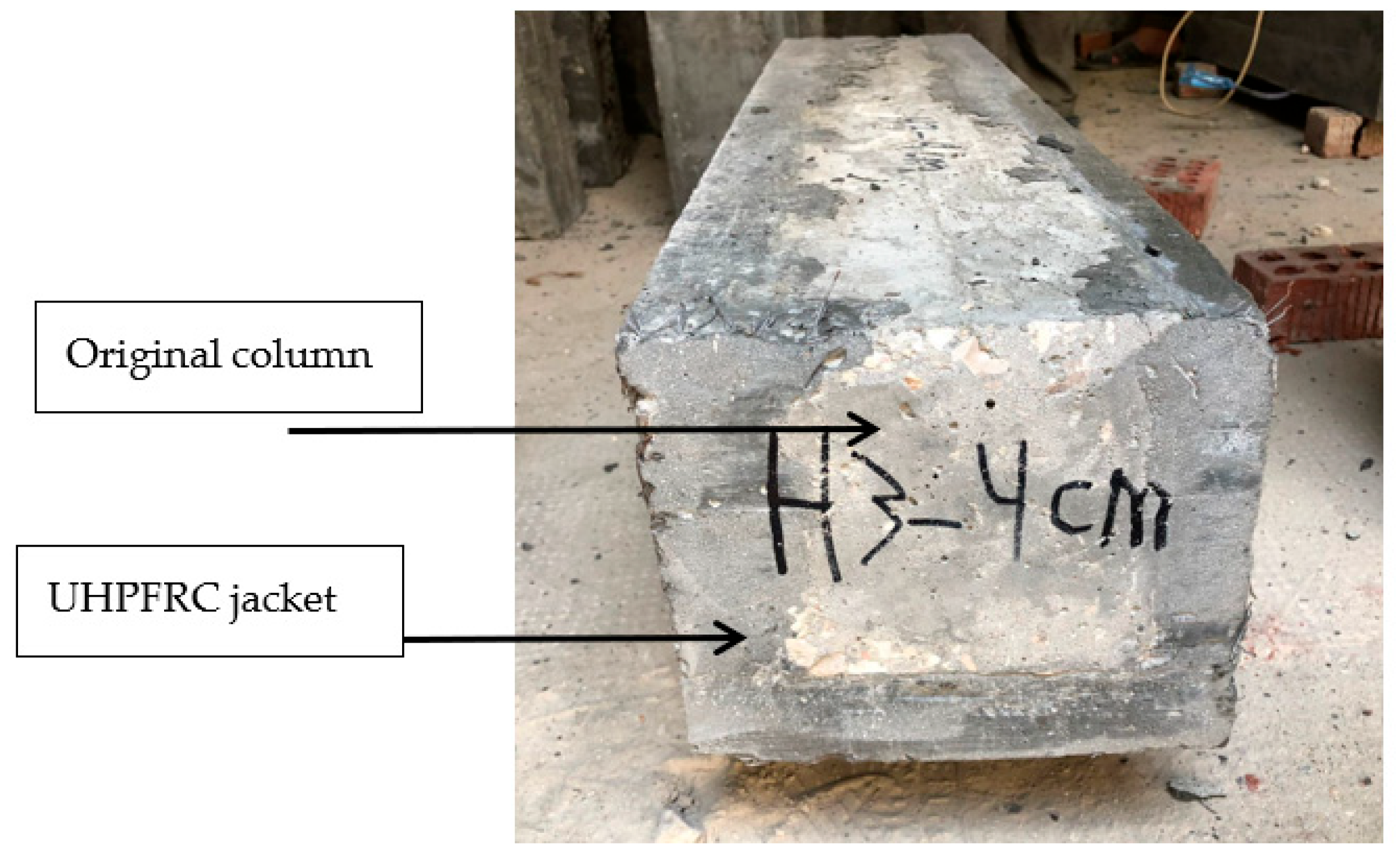
The experimental program included the casting and testing of nineteen square column specimens with a height of 1000 mm and a cross-sectional area of 150 × 150 mm. The longitudinal reinforcing bars used consisted of four 10 mm deformable bars, and the transverse reinforcing bars consisted of 6 mm reinforcing bars at 100 mm spacing. A 20 mm thick transparent concrete cover was used to cover the bars. The details of the specimens are shown in Figure 1. The test program was designed to include the following parameters: jacket thickness (20 mm and 40 mm), number of strengthened sides of the column (two, three, and four sides), and interface treatment methods (vertical grooving (VG), horizontal grooving (HG), and without grooving (NG)), as shown in Figure 2, Figure 3, and Table 1.

2.2. Material Properties and Preparation of Normal Columns

2.2.1. Steel Reinforcing Bars and Normal Concrete (NC)

Both 10 mm and 6 mm diameter bars were used as main reinforcement and transverse reinforcement, respectively. The yield strength and ultimate strength of the 6 mm bars were measured to be 240 and 350 MPa, respectively, and the yield strength and ultimate strength of the 10 mm bars were measured to be 360 and 520 MPa, respectively.
From a normal concrete (NC) mix with compressive strength of 24 MPa used for casting normal columns, three standard cubes (150 × 150 ×150 mm) were cast from each batch and tested after 28 days, where each of the five specimens were cast from one batch. The absolute volume method recommended by the ACI Committee was used to calculate the amount of material required for the test batch of the NC mixture proportion. Normal concrete (NC) mix design details are presented in Table 2.
A normal concrete (NC) mix has a plastic consistency with a slump value of 80 mm. The slump test was used to measure the consistency of fresh concrete.

2.2.2. Aggregate Properties

Coarse Aggregate

Two sizes of natural crushed dolomite were used with the mixing ratio (1:1), where size one was graded from 4.76 mm to 14.0 mm (max. nominal size), and size two was graded from 4.76 mm to 20.0 mm (max. nominal size). Sieve analysis was carried out to obtain the best grading of the used aggregates. Table 3 and Table 4 show the size gradation of the used aggregates. The coarse aggregates were tested according to the Egyptian Standard Specification 1109/2002 [20].

Fine Aggregate

Clean siliceous sand was used as fine aggregates, where the sand was washed to clean it and free it from any impurities. Sieve analysis was carried out to obtain the grading of the used sand, where the grading of sand is shown in Table 5. The fine aggregates were tested according to the Egyptian Standard Specification 1109/2002 [20].

2.2.3. Cement and Mixing Water

Portland pozzolana cement (CEMII/B-P 42.5N) was used for casting the normal columns, and clean tap water without additives was used with a constant water/cement ratio of 0.5 water for all mixes.

2.2.4. Curing

After concreting, the samples were left in the mold for 24 h, then the sides of the mold were removed, and the control cubes were taken. The samples were then covered with a wet cloth and treated for 28 days under the same conditions as the cubes, as shown in Figure 4.

2.3. Material Properties and Preparation of Jacket Concrete (UHPFRC)

The amounts of the UHPFRC components, which are shown in Table 6, were determined based on previous studies. UHPFRC has low workability due to the decrease in water content, so superplasticizers were used to improve the workability of fresh concrete. To evaluate the workability of UHPFRC, the flow table tests were performed for the relative slump value (ξp) (1.3). A UHPFRC mix was given compressive strength of 125.75 MPa and tensile strength of (13 MPa), and six standard concrete cubes (100 × 100 × 100 mm) and three standard concrete cylinders (100 × 200 mm) were cast to obtain compressive and tensile strengths, respectively. A good dispersion was obtained by premixing the dry ingredients (cement, silica, sand, and quartz) at a low speed for about 5 min. Then, the superplasticizer was added to the mixed water and mixed well. The water and superplasticizer were then added to the dry mixture and mixed at a low speed for an additional 10 min. When the mixture had sufficient fluidity and viscosity, the steel fibers were lightly dispersed and mixed at a high speed for another 5 min.
The formworks of the specimens were prepared with a clear dimension of 150 × 150 mm and a height of 1000 mm, inside which the reinforcement cages were subsequently placed. The NSC was cast inside the formworks, compacted, and left to be hardened for one day before they were removed from the molds to be cured under laboratory conditions for 28 days. After the curing period, new formworks were prepared with dimensions according to the jacket thickness (20 mm and 40 mm) and the number of strengthened sides of the column (two, three, and four sides). The surface of the column was cleaned and painted with KEMAPOXY104, then placed inside the formworks before casting the UHPFRC jackets, and then we left the UHPFRC-jacketed specimens to be hardened for one day before they were removed from the molds to be cured under laboratory conditions for 28 days.

2.3.1. Cement and Mixing Water

Ordinary Portland cement (CEMI/52.5N) was used for casting the jacket concrete (UHPFRC), and clean tap water without additives was used with a constant water/cement ratio of 0.137 water for all mixes.

2.3.2. Aggregate Properties

Clean siliceous sand was chosen as aggregates for the UHPFRC jacket used in this experimental program. The sand grain size ranges from 0.1 mm to 0.8 mm. The sand was washed to clean it and free it from any impurities. Sieve analysis was carried out to obtain the grading of the used sand. The grading of sand is shown in Table 7. The aggregates were tested according to the Egyptian Standard Specification 1109/2002 [20].

2.3.3. Silica Fume and Quartz Properties

The silica fume used was produced by Sika Egypt (Sika Fume-HR). Table 8 shows the physical and chemical properties. The quartz used was produced by (VENICE MINERALS & STONES, S.A.E.), with Chemical name (Silicon Dioxide) and Chemical formula (SiO2). Table 9 shows the physical and chemical properties.

2.3.4. Super Plasticizer Properties

Master Ease 3977 is the latest generation of innovative water-reducing agents based on polyaryl ether (PAE) polymers. Superplasticizers have been shown to have a strong self-leveling action and thus improve the properties of ready-mixed, fresh, and hardened UHPFRC concrete. This plasticizing effect can be used to increase the workability of fresh concrete, improve shrinkage and creep behavior, and ultimately improve waterproofing without segregation, water loss (resulting in higher density, strength, and durability), and greater fluidity. Table 10 shows the characteristics of the superplasticizer used.

2.3.5. Steel Fibers Properties

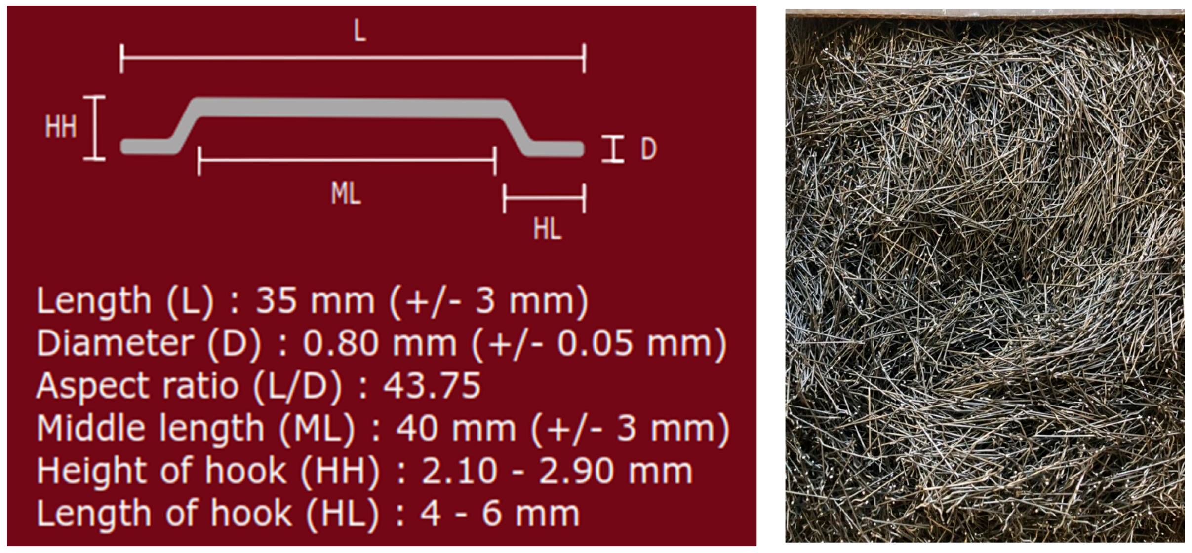
Steel fiber is a reinforcing material made from cold rolled wire to improve the mechanical properties of concrete. Steel fibers with tensile strength of 1100 MPa, diameter of 0.8 mm, length of 35 mm, and a hooked end were used in the jacket concrete (UHPFRC), as shown in Figure 5.

2.3.6. Curing

After casting the UHPFRC jacket, the specimen was left in the mold for 24 h and then the side of the mold was removed. The samples were then covered with a wet cloth and cured for 28 days under the same conditions as the cubes, as shown in Figure 6.

2.4. Test Specimens

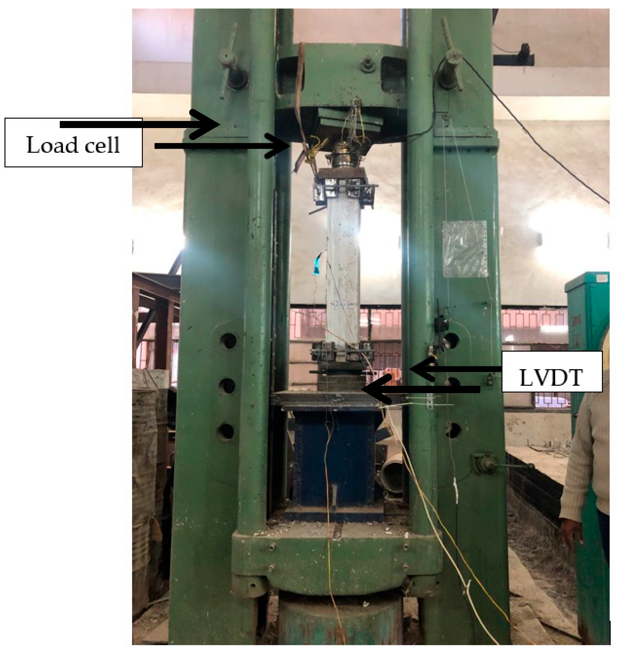
The columns were tested using a monotonic axial compressive loading system at the columns’ ends via a hydraulic jack and a reaction frame of a 320-ton capacity. Figure 7 shows the loading arrangement and the overall test setup, where the load was applied at a fixed rate of 1.0 mm/min under displacement control.
Before testing, the specimens were painted with a white plastic coating to facilitate the detection of cracks during testing. The columns were tested till failure for both the control columns, which were tested without any application of the strengthening technique, and the columns group, which were strengthened using a UHPFRC jacket.These conditions were taken into account to keep the load constant via a continuous follow up for the load readings over short periods to avoid any load release. Finally, the columns were loaded till failure.

3. Results and Discussion

3.1. Modes of Failure

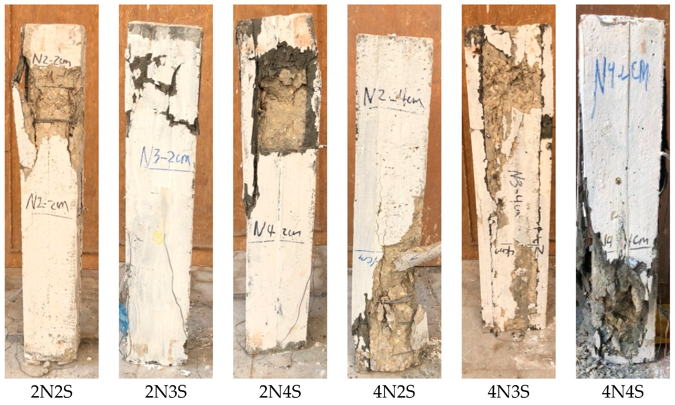
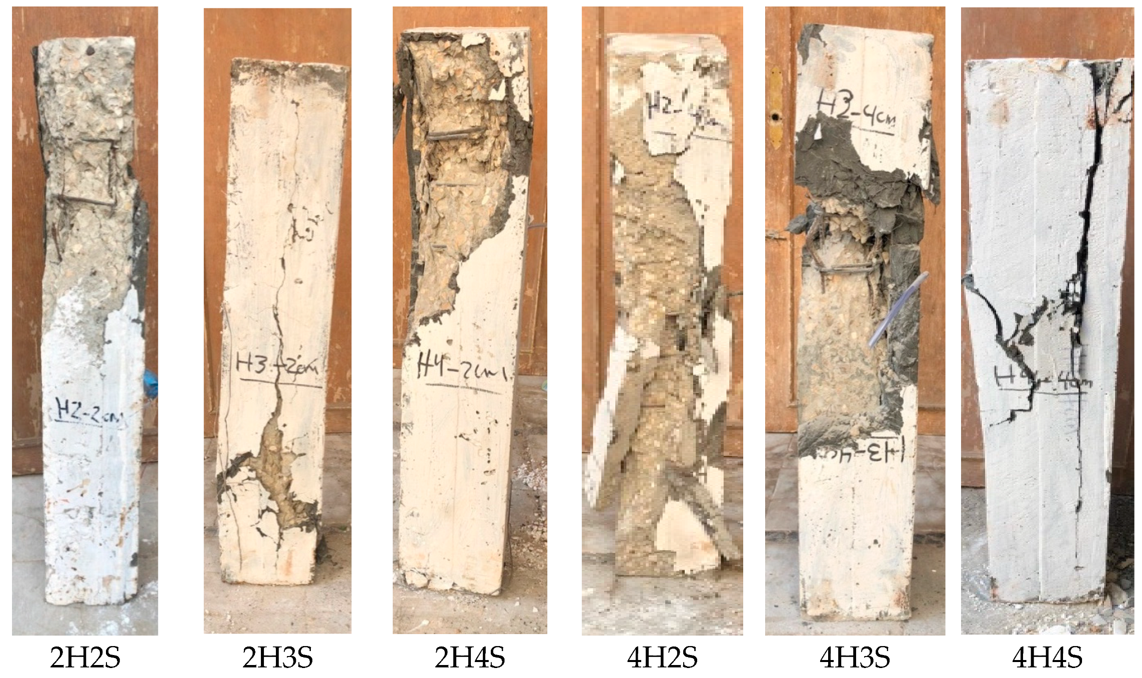
The failure modes of the tested columns are presented in Table 11. The typical mode of failure was observed during the tests, as shown in Figure 8, Figure 9 and Figure 10). The mode of failure can be described as a brittle failure that occurs at the maximum load capacity of the column and occurs in the original column, followed directly by the breaking of the UHPFRC jacket and the occurrence of a buckling in the steel as a result of the failure of the concrete.

3.2. Effect of Number of Strengthened Sides of Column

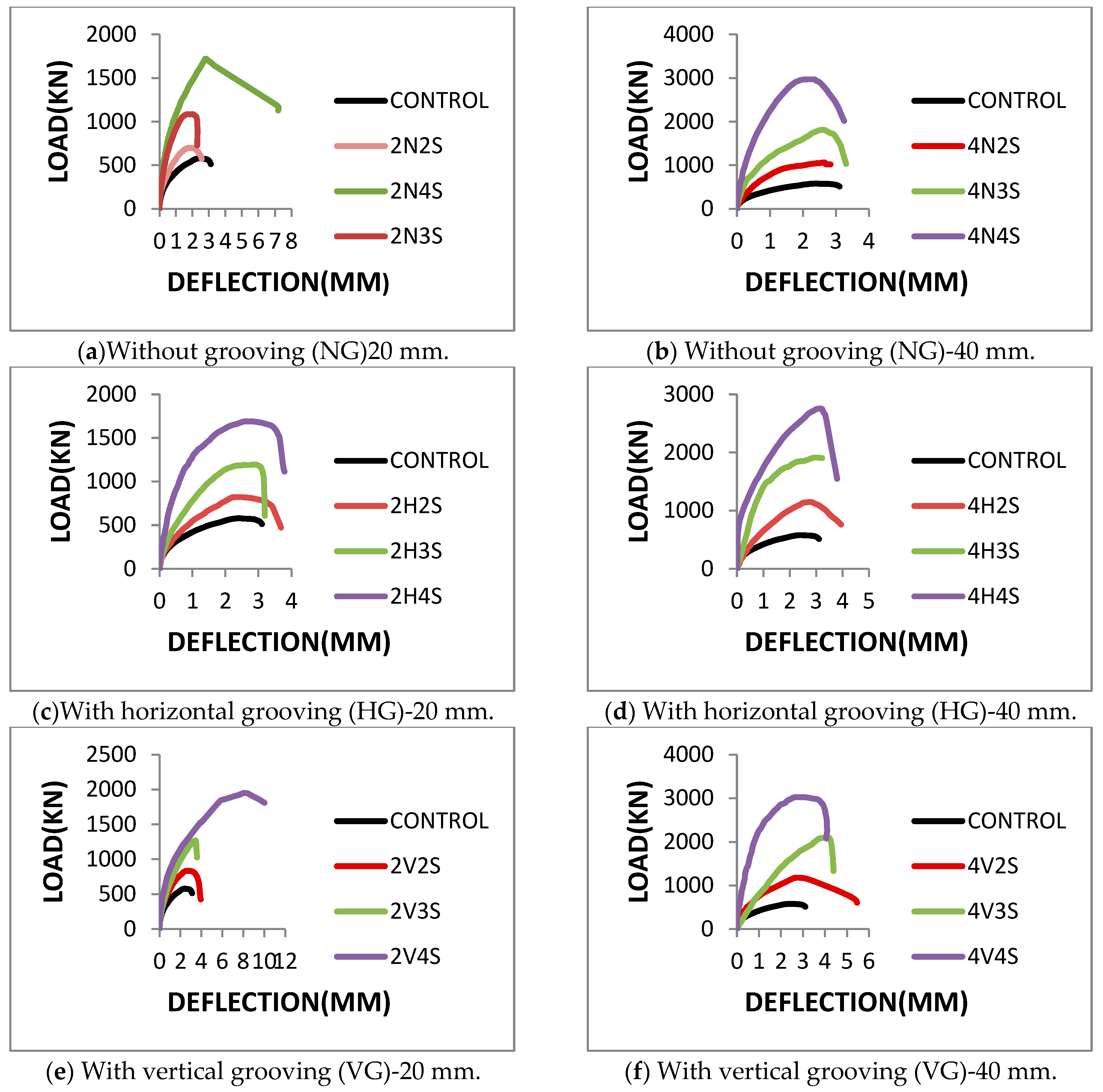
Compared to the control column, specimens 2N2S, 2N3S, and 2N4S that have been strengthened with a 20 mm UHPFRC jacket without grooving (NG) achieved a load increase by 21.0%, 87.5%, and 197%, respectively, as shown in Table 11 and Figure 11a, while specimens 4N2S, 4N3S, and 4N4S that have been strengthened with a 40 mm UHPFRC jacket achieved a load increase by 83.5%, 212.8%, and 412.5%, respectively, as shown in Table 11 and Figure 11b.
Specimens 2H2S, 2H3S, and 2H4S that have been strengthened with a 20 mm UHPFRC jacket with horizontal grooving (HG) achieved a load increase by 41.9%, 106.4%, and 191.5%, respectively, as shown in Table 11 and Figure 11c, while specimens 4H2S, 4H3S, and 4H4S that have been strengthened with a 40 mm UHPFRC jacket achieved a load increase by 98.6%, 230.4%, and 375.7%, respectively, as shown in Table 11 and Figure 11d.
Specimens 2V2S, 2V3S, and 2V4S that have been strengthened with a 20 mm UHPFRC jacket with vertical grooving (VG) achieved a load increase by 44.4%, 119.4%, and 236.4%, respectively, as shown in Table 11 and Figure 11e. This is while specimens 4V2S, 4V3S, and 4V4S that have been strengthened with a 40 mm UHPFRC jacket achieved a load increase by 103.2%, 264.3%, and 421.8%, respectively, as shown in Table 11 and Figure 11f.
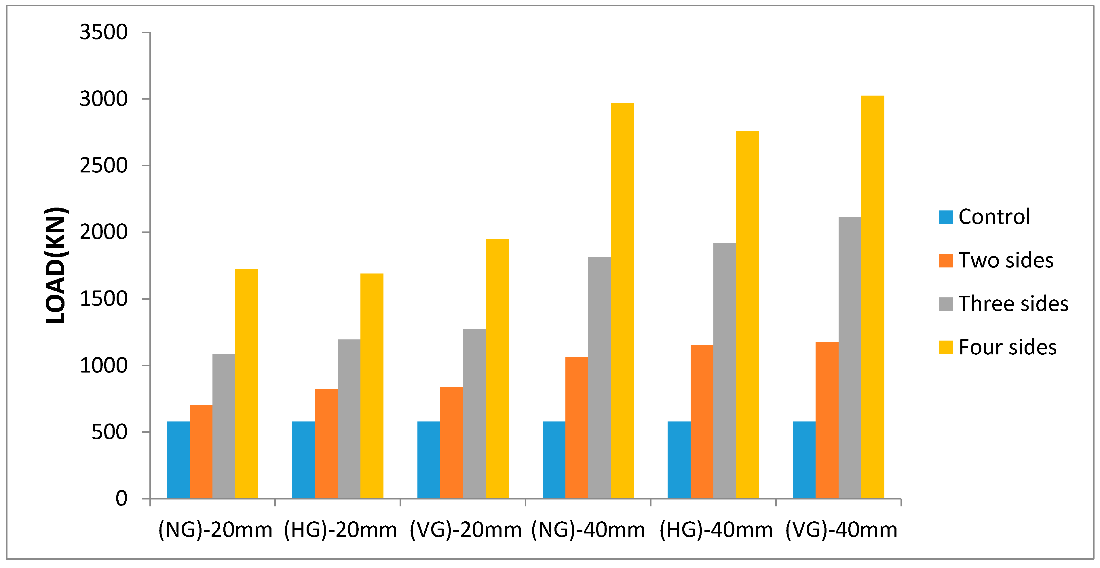
Table 11 shows the ultimate loads of the control column and strengthened columns, where it is observed that the ultimate loads of the strengthened columns increase with the increase in the number of strengthened column sides not only increasing the cross-section area of the jacket, but also maximizing the confining value regardless of the jacket thickness or interface treatment methods, as shown in Figure 12.
The confinement load can be estimated from the experimental results as follows: for two-sided UHPFRC-strengthened columns (no confinement effect), the ultimate load carrying capacity is a contribution between the ultimate capacity of the control column in addition to the load carrying capacity of the UHPFRC jacket. As for three-sided UHPFRC-strengthened columns (partial confinement) and four-sided UHPFRC-strengthened columns (full confinement), the confinement load can be estimated as described in detail in Table 12, where the increase in the cross-section area of the UHPFRC jacket is proportional to the cross-section area of the UHPFRC jacket for the two-sided UHPFRC-strengthened columns (no confinement effect).

3.3. Effect of Interface Treatment Methods

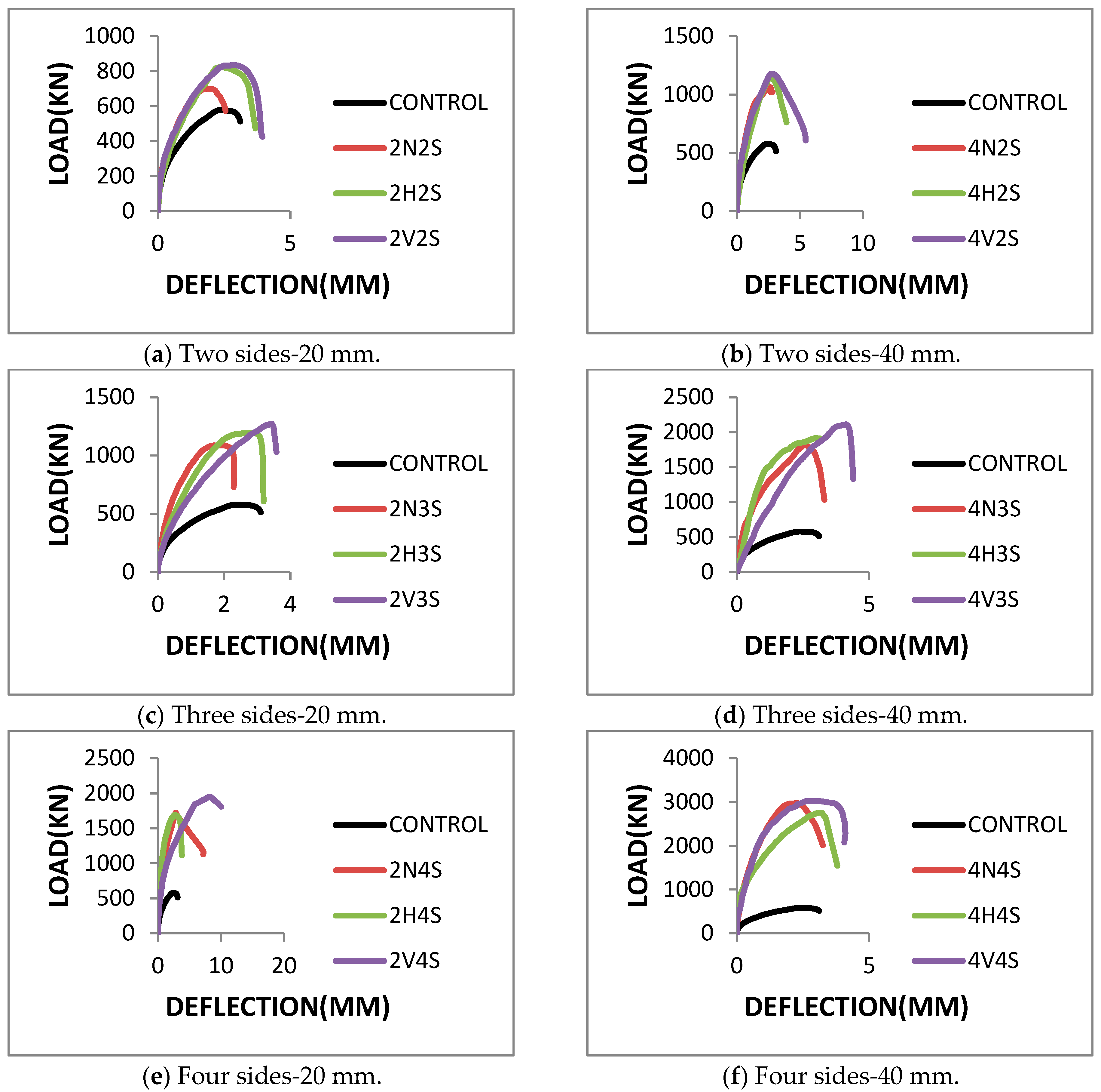
Compared to the control column, specimens 2N2S, 2H2S, and 2V2S that have strengthened two sides of column with a 20 mm UHPFRC jacket achieved a load increase by 21.0%, 41.9%, and 44.4%, respectively, as shown in Table 11 and Figure 13a. This is while specimens 4N2S, 4H2S, and 4V2S that have been strengthened with a 40 mm UHPFRC jacket achieved a load increase by 83.5%, 98.6%, and 103.2%, respectively, as shown in Table 11 and Figure 13b.
Specimens 2N3S, 2H3S, and 2V3S that have strengthened three sides of column with a 20 mm UHPFRC jacket achieved a load increase by 87.5%, 106.4%, and 119.4%, respectively, as shown in Table 11 and Figure 13c. This is while specimens 4N3S, 4H3S, and 4V3S that have been strengthened with a 40 mm UHPFRC jacket achieved a load increase by 212.8%, 230.4%, and 264.3%, respectively, as shown in Table 11 and Figure 13d.
Specimens 2N4S, 2H4S, and 2V4S that have strengthened three sides of column with a 20 mm UHPFRC jacket achieved a load increase by 197.0%, 191.5%, and 236.4%, respectively, as shown in Table 11 and Figure 13e. This is while specimens 4N4S, 4H4S, and 4V4S that have been strengthened with a 40 mm UHPFRC jacket achieved a load increase by 412.5%, 375.7%, and 421.8%, respectively, as shown in Table 11 and Figure 13f.
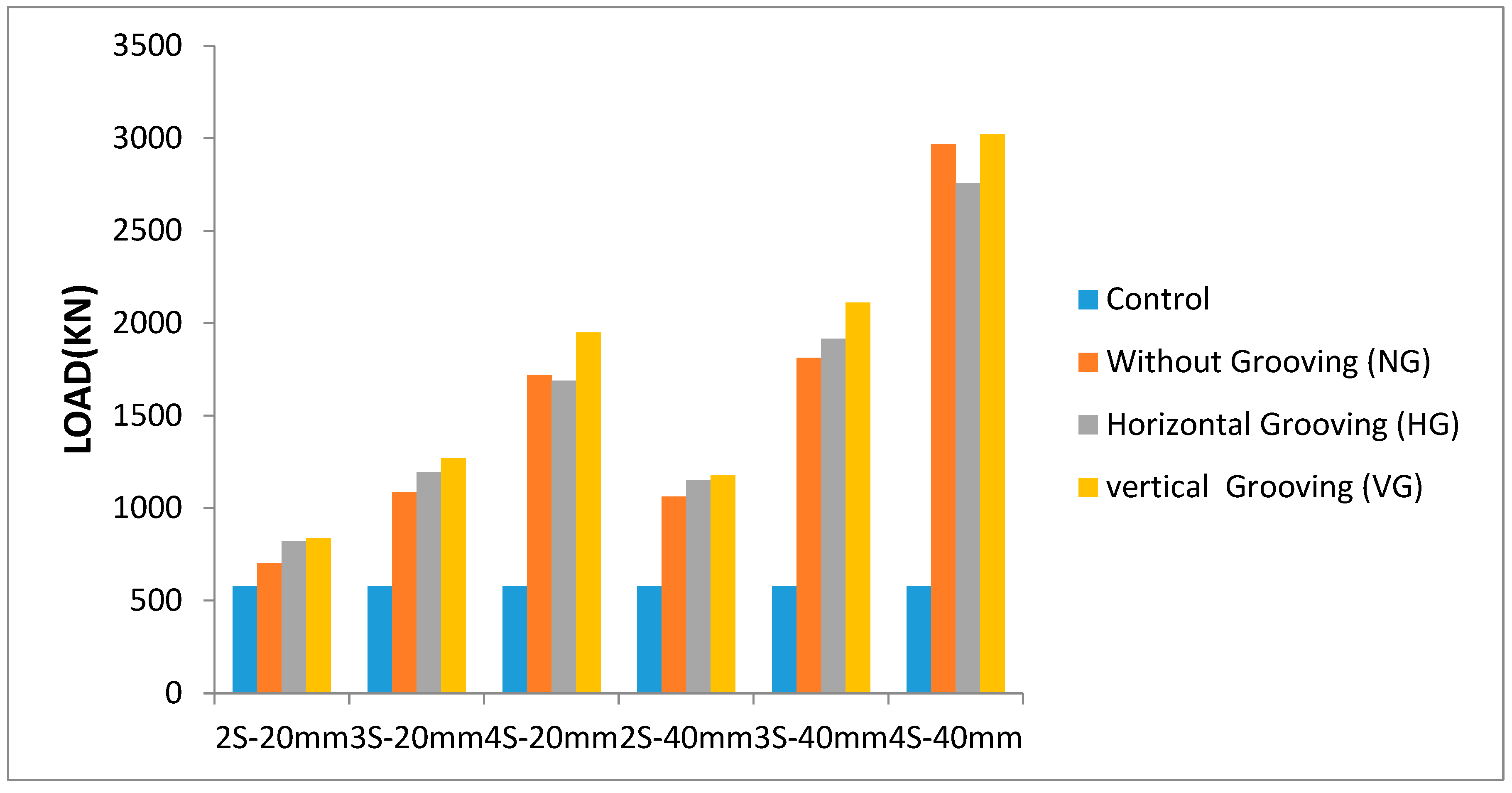
Figure 14 shows the ultimate loads of the control column and strengthened columns at different interface treatment methods (vertical grooving (VG), horizontal grooving (HG), and without grooving (NG)).It is observed that the vertical grooving (VG) method has achieved good results compared to the other interface treatment methods regardless of the jacket thickness or number of strengthened column sides. This increase is attributed to the increase in the cohesion area between the column surface and jacket, and the area of the UHPFRC jacket is greater than the case of horizontal grooving (HG) or without grooving (NG) at the entire height of the column.
In case of the strengthening of the two or three sides using the horizontal grooving (HG) technique, this improves the results compared to the jacket using the without grooving (NG) technique, and this improvement is caused due to increasing the cohesion area between the column surface and the jacket. But in the case of strengthening the four sides using the without grooving (NG) technique, the results are better than strengthening the four sides using the horizontal grooving (HG) technique. This change is due to the effect of confining the column jacket, and grooving causes weakness in the body of the original column.

3.4. Effect of Jacket Thickness

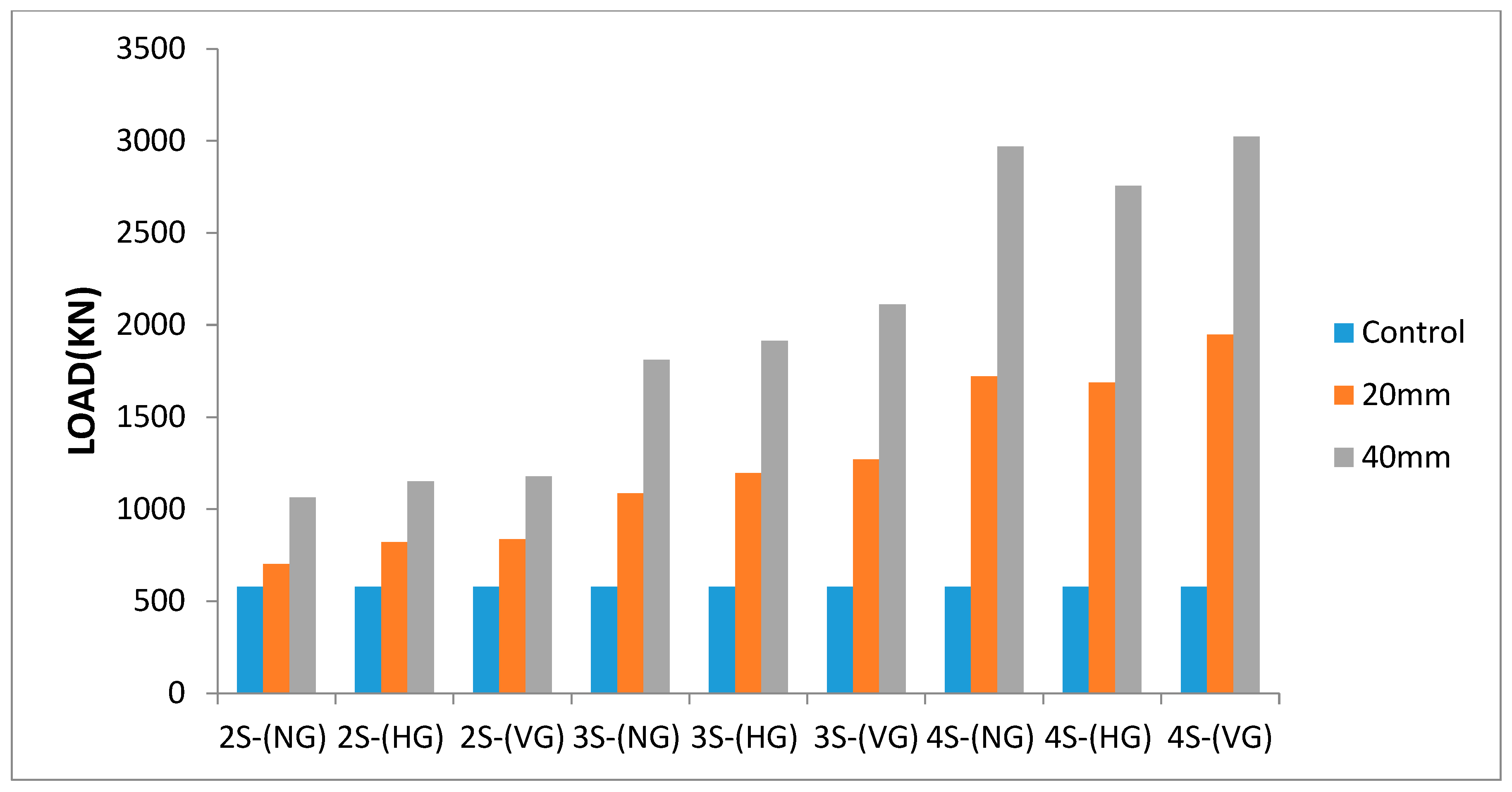
The ultimate load carrying capacity of the RC columns strengthened using the UHPFRC jacket is greatly affected by the jacket thickness, regardless of the interface treatment methods or number of strengthened sides of the column, as shown in Figure 15.

4. Conclusions

The objective of this study investigates the strengthening methods of UHPFRC jacketing for confining square RC columns. Nineteen specimens were cast with 1000 mm in height and a cross-section area of 150 × 150 mm was cast as base specimens. A total of 18 of the base square RC columns were subjected to the strengthening test program that was designed to include the following parameters: jacket thickness (20 mm and 40 mm), the number of strengthened sides of the column (two, three, and four sides), and interface treatment methods (vertical grooving (VG), horizontal grooving (HG), and without grooving (NG)). The results from this research show the following:
  • The failure was a brittle failure that occurs at the maximum load capacity of the column and occurs in the original column, followed directly by the breaking of the UHPFRC jacket and the occurrence of a buckling in the steel as a result of the failure of the concrete.
  • In the case of strengthening the columns in two, three, and four sides, the improvement of the ultimate load carrying capacity of the RC columns are better strengthened using the UHPFRC jacket in the case of vertical grooving (VG).
  • Horizontal grooving (HG) gives a better result than the jacket without grooving (NG) to increase the cohesion area between the jacket and the column. But in the case of strengthening the columns in four sides, the effect of confining the jacket to the column appears, and the grooving causes weakness in the body of the original column so that the jacket without grooving (NG) gives a better result than the jacket with horizontal grooving (HG).
  • In the case of the specimens strengthened with the UHPFRC jacket and vertical grooving (VG), the average load increases by 44.4%, 119.4%, and 236.4% in the case of strengthening the columns with jacket thickness (20 mm) in two, three, and four sides, respectively. While the average load increases by 103.2%, 264.3%, and 421.8%, respectively, in the case of jacket thickness (40 mm).
  • In the case of the specimens strengthened with the UHPFRC jacket and horizontal grooving (HG), the average load increases by 41.9%, 106.4%, and 191.5%, in the case of strengthening the column with jacket thickness (20 mm) in two, three, and four sides, respectively. While the average load increases by 98.6%, 230.4%, and 375.7%, respectively, in the case of jacket thickness (40 mm)
  • In the case of the specimens strengthened with the UHPFRC jacket and without grooving (NG), the average load increases by 21.0%, 87.5%, and 197.0%, in the case of strengthening the column with jacket thickness (20 mm) in two, three and four sides, respectively. While the average load increases by 83.5%, 212.8%, and 412.5%, respectively, in the case of jacket thickness (40 mm)

Author Contributions

Conceptualization, A.E.; Methodology, A.M.W.; Validation, P.S.; Formal analysis, H.S.; Investigation, A.M.W.; Resources, H.S. and P.S.; Data curation, H.S.; Writing—original draft, A.M.W. and P.S.; Writing—review and editing, D.K.; Visualization, D.K.; Supervision, A.E.; Project administration, A.E. All authors have read and agreed to the published version of the manuscript.

Funding

This research received no external funding.

Data Availability Statement

Data is contained within the article.

Conflicts of Interest

The authors declare no conflict of interest.

References

  1. Fukuyama, K.; Higashibata, Y.; Miyauchi, Y. Studies on repair and strengthening methods of damaged reinforced concrete columns. Cem. Concr. Compos. 2000, 22, 81–88. [Google Scholar] [CrossRef]
  2. Frangou, M.; Pilakoutas, K.; Dritsos, S. Structural repair/strengthening of RC columns. Constr. Build. Mater. 1995, 9, 259–266. [Google Scholar] [CrossRef]
  3. Sheikh, S.A. Performance of concrete structures retrofitted with fiber reinforced polymers. Eng. Struct. 2002, 24, 869–879. [Google Scholar] [CrossRef]
  4. Hadi, M.N.; Algburi, A.H.; Sheikh, M.N.; Carrigan, A.T. Axial and flexural behavior of circular reinforced concrete columns strengthened with reactive powder concrete jacket and fiber reinforced polymer wrapping. Constr. Build. Mater. 2018, 172, 717–727. [Google Scholar] [CrossRef] [Green Version]
  5. Can, H. Partially jacketed (two, three, four sides) reinforced concrete column behavior under uni-axial loading. Tek. Dergi Tmmob Insa. Muhendisleri Odasi 1995, 6, 337–342. [Google Scholar]
  6. Vandoros, K.G.; Dritsos, S.E. Concrete jacket construction detail effectiveness when strengthening RC columns. Constr. Build. Mater. 2008, 22, 264–276. [Google Scholar] [CrossRef]
  7. Campione, G. Strength and ductility of RC columns strengthened with steel angles and battens. Constr. Build. Mater. 2012, 35, 800–807. [Google Scholar] [CrossRef]
  8. Allam, M.H. Strengthening of Loaded Columns by RC Jackets; Faculty of Engineering, Cairo University: Cairo, Egypt, 1995. [Google Scholar]
  9. Meda, A.; Plizzari, G.A.; Rinaldi, Z. Strengthening of RC Existing Columns with High Performance Fiber Reinforced Concrete Jacket; University of Bergamo: Bergamo, Italy, 2009. [Google Scholar]
  10. Dadvar, S.A.; Mostofinejad, D.; Bahmani, H. Strengthening of RC columns by ultra-high performance fiber reinforced concrete (UHPFRC) jacketing. Constr. Build. Mater. 2020, 235, 117485. [Google Scholar] [CrossRef]
  11. Ma, C.K.; Apandi, N.M.; Sofrie, C.S.Y.; Ng, J.H.; Lo, W.H.; Awang, A.Z.; Omar, W. Repair and rehabilitation of concrete structures using confinement: A review. Constr. Build. Mater. 2017, 133, 502–515. [Google Scholar] [CrossRef]
  12. Roux, N.; Andrade, C.; Sanjuan, M.A. Experimental study of durability of reactive powder concretes. J. Mater. Civ. Eng. 1996, 8, 1–6. [Google Scholar] [CrossRef]
  13. Magureanu, C.; Sosa, I.; Negrutiu, C.; Heghes, B. Mechanical Properties and Durability of Ultra-High-Performance Concrete. ACI Mater. J. 2012, 109, 177–183. [Google Scholar]
  14. Abbas, S.; Soliman, A.M.; Nehdi, M.L. Exploring mechanical and durability properties of ultra-high performance concrete incorporating various steel fiber lengths and dosages. Constr. Build. Mater. 2015, 75, 429–441. [Google Scholar] [CrossRef]
  15. Graybeal, B.A.; Hartmann, J.L. Strength and durability of ultra-high performance concrete. In Proceedings of the Concrete Bridge Conference, Taupo, New Zealand, 3–5 October 2003; p. 20. [Google Scholar]
  16. Karadogan, H.F. Local thin jacketing for the retrofitting of reinforced concrete columns. Struct. Eng. Mech. 2007, 27, 589–607. [Google Scholar]
  17. Helles, Z.H. Strengthening of Square Reinforced Concrete Columns with Fibrous Ultra-High Performance Self-Compacting Concrete Jacketing; The Islamic University Gaza: Gaza, Palestine, 2014. [Google Scholar]
  18. Elsayed, M.; Tayeh, B.A.; AbouElmaaty, M.; Aldahshoory, Y. Behavior of RC columns strengthened with Ultra-High Performance Fiber Reinforced concrete (UHPFRC) under eccentric loading. J. Build. Eng. 2022, 47, 103857. [Google Scholar] [CrossRef]
  19. Susilorini, R.M.R.; Kusumawardaningsih, Y. Advanced Study of Columns Confined by Ultra-High-Performance Concrete and Ultra-High-Performance Fiber-Reinforced Concrete Confinements. Fibers 2023, 11, 44. [Google Scholar] [CrossRef]
  20. ES 1109/2002; Concrete Aggregates from Natural Sources. Egyptian Organization for Standardization & Quality: Cairo, Egypt, 2002.
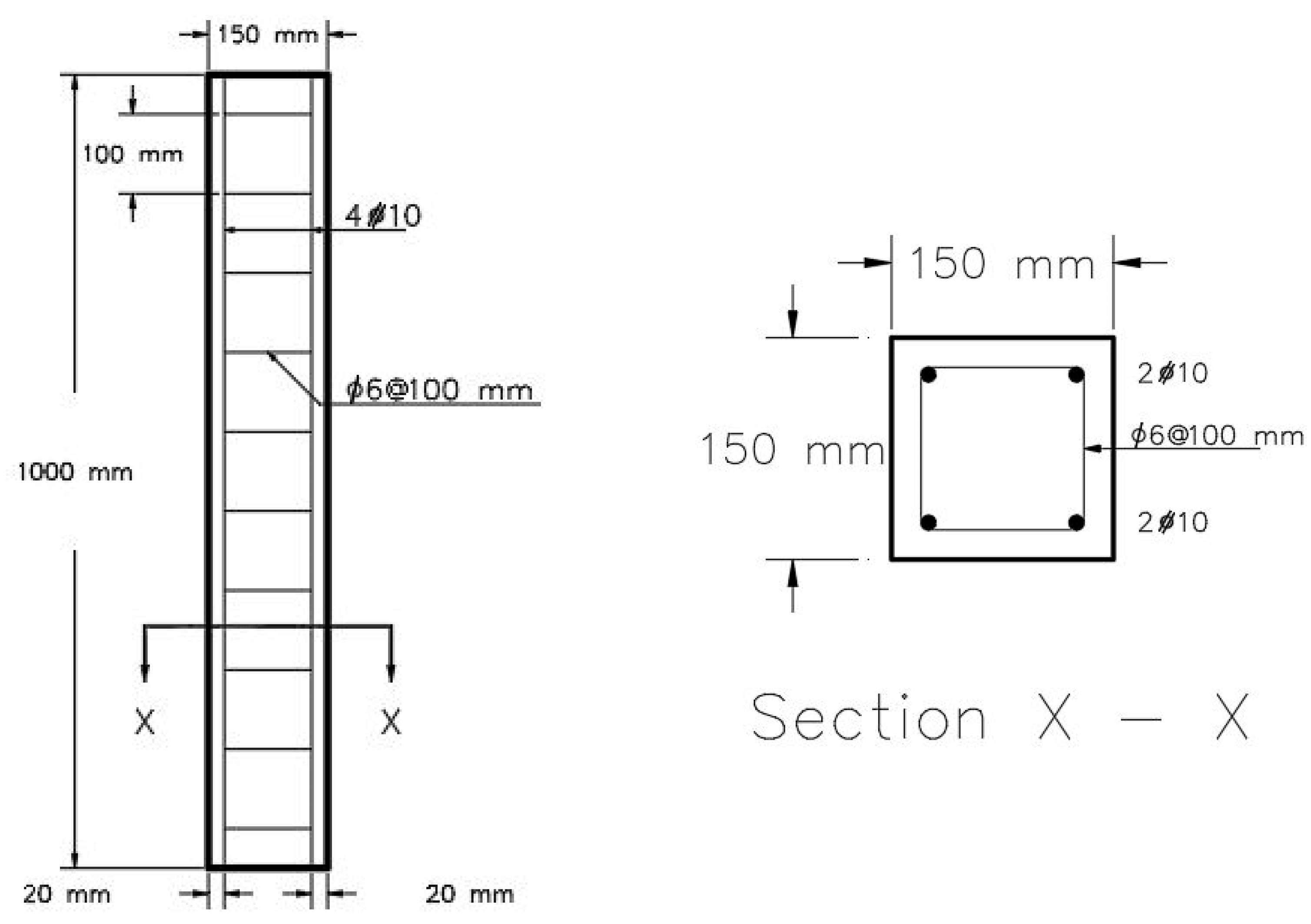
Figure 1. Test specimens.
Buildings 13 02036 g001
Figure 2. Strengthen test specimens.
Buildings 13 02036 g002
Figure 3. Specimen after UHPFRC jacket.
Buildings 13 02036 g003
Figure 4. Curing columns.
Buildings 13 02036 g004
Figure 5. Steel Fiber.
Buildings 13 02036 g005
Figure 6. Curing Specimens.
Buildings 13 02036 g006
Figure 7. Loading arrangement and test setup.
Buildings 13 02036 g007
Figure 8. Failure Mode of the Strengthened Column Without Grooving (NG).
Buildings 13 02036 g008
Figure 9. Failure Mode of the Strengthened Column with Horizontal Grooving (HG).
Buildings 13 02036 g009
Figure 10. Failure Mode of the Strengthened Column with Vertical Grooving (VG).
Buildings 13 02036 g010
Figure 11. Load—deflection curve (Effect of the number of strengthened sides of the column).
Buildings 13 02036 g011
Figure 12. The effect of the number of sides strengthened of the column.
Buildings 13 02036 g012
Figure 13. Load—deflection curve (Effect of interface treatment).
Buildings 13 02036 g013
Figure 14. Effect of interface treatment techniques.
Buildings 13 02036 g014
Figure 15. Effect of the jacket thickness.
Buildings 13 02036 g015
Table 1. Groups details and test program.
GroupSpecimenJacket ThicknessNumber of Strengthened SidesInterface MethodsSpecimen Dimension
1Control---------------150 × 150 mm
22N2S20 mm2without grooving170 × 170 mm
2V2S20 mm2vertical grooving170 × 170 mm
2H2S20 mm2horizontal grooving170 × 170 mm
32N3S20 mm3without grooving190 × 170 mm
2V3S20 mm3vertical grooving190 × 170 mm
2H3S20 mm3horizontal grooving190 × 170 mm
42N4S20 mm4without grooving190 × 190 mm
2V4S20 mm4vertical grooving190 × 190 mm
2H4S20 mm4horizontal grooving190 × 190 mm
54N2S40 mm2without grooving190 × 190 mm
4V2S40 mm2vertical grooving190 × 190 mm
4H2S40 mm2horizontal grooving190 × 190 mm
64N3S40 mm3without grooving230 × 190 mm
4V3S40 mm3vertical grooving230 × 190 mm
4H3S40 mm3horizontal grooving230 × 190 mm
74N4S40 mm4without grooving230 × 230 mm
4V4S40 mm4vertical grooving230 × 230 mm
4H4S40 mm4horizontal grooving230 × 230 mm
Table 2. Normal concrete (NC) Mix Design Details.
Coarse Aggregate (Size 1)Coarse Aggregate (Size 2)Fine Aggregate (Sand)CementWater
671 kg/m3671 kg/m3671 kg/m3300 kg/m3150 kg/m3
Table 3. Grading of the used aggregates (size 1).
Sieve opening (mm) 2014104.76
% Passing10096.945.030.6
Table 4. Grading of the used aggregates (size 2).
Sieve opening (mm) 2014104.76
% Passing81.713.90.20.0
Table 5. Grading of the used sand.
Sieve opening (mm) 52.361.180.600.300.15
% Passing9892.676.848.4142.8
Table 6. UHPFRC Mix Design Details.
CementSandQuartz PowderSlice FumeWaterSuperplasticizerSteel Fiber
950 kg/m3690 kg/m3220 kg/m3231 kg/m3130 kg/m330 kg/m3152 kg/m3
Table 7. Grading of the used sand in UHPFRC.
Sieve opening (mm) 0.600.300.15pan
% Passing93.432.45.40.0
Table 8. Physical and chemical properties of silica fume.
PropertyMeasured ValuesLimitations
Physical properties
ColorLight gray--
Specific gravity2.15--
Bulk density (kg/cm2)340250–450 kg/m3
Chemical properties
SiO297%90% min
C0.5%1% max
Fe2O30.5%1.5% max
Al2O30.2%1% max
CaO0.2%1% max
MgO0.5%1.5% max
K2O0.5%1.5% max
Na2O0.2%0.5% max
SO30.15%0.2% max
Cl<0.01%0.05% max
H2O0.5%0.8% max
Table 9. Physical and chemical properties of quartz.
PropertyMeasured Values
Physical properties
ColorWhite
Specific gravity2.60
Grain Shapeangular
Moisture0.02%
Chemical properties
SiO299.76
TiO20.005
Al2O30.01
Fe2O30.039
Mno20.006
MgO0.002
Cao0.012
Na2O0.008
K2O0.006
P2O50.007
Table 10. Properties of Master Ease 3977.
AppearanceSpecific GravityPH ValueChloride Content
Brown colored liquid1.075.0–7.0“Chloride-free” to EN934-2
Table 11. Ultimate loads and failure modes of the tested columns.
GroupSpecimenUltimate Load (KN)Ultimate Deflection (mm)Load
Increase %
Concrete Ultimate StrainFailure Mode
1Control579.32.422----------brittle failure
22N2S7011.83621%without groovingbrittle failure
2V2S836.52.81844.4%vertical groovingbrittle failure
2H2S8222.48841.9%horizontal groovingbrittle failure
32N3S1086.12.02687.5%without groovingbrittle failure
2V3S1270.93.443119.4%vertical groovingbrittle failure
2H3S1195.42.909106.4%horizontal groovingbrittle failure
42N4S1720.72.836197%without groovingbrittle failure
2V4S1948.928.205236.4%vertical groovingbrittle failure
2H4S1688.72.851191.5%horizontal groovingbrittle failure
54N2S1063.052.65683.5%without groovingbrittle failure
4V2S1177.262.674103.2%vertical groovingbrittle failure
4H2S1150.742.78798.6%horizontal groovingbrittle failure
64N3S1812.092.632212.8%without groovingbrittle failure
4V3S2110.314.137264.3%vertical groovingbrittle failure
4H3S1914.282.981230.4%horizontal groovingbrittle failure
74N4S2968.982.353412.5%without groovingbrittle failure
4V4S3022.963.080421.8%vertical groovingbrittle failure
4H4S2755.713.190375.7%horizontal groovingbrittle failure
Table 12. Estimation of the confinement load contributed by the UHPFRC jacket of the tested columns.
N-20mmH-20mmV-20mmN-40MMH-40MMV-40MM
two sidesUltimate load (P)-(KN)701822836.51063.051150.741177.26
Control column load (P0)-(KN)579.3579.3579.3579.3579.3579.3
cross section jacket area (A0)-(mm)64006400640013,60013,60013,600
jacket load(P1)-(KN)121.7242.7257.2483.75571.44597.96
three sidesUltimate load (P)-(KN)1086.11195.41270.91812.091914.282110.31
Control column load (P0)-(KN)579.3579.3579.3579.3579.3579.3
cross section jacket area (A1)-(mm)98009800980021,20021,20021,200
A1/A01.541.541.541.561.561.56
jacket load(P2)-(KN)187.42373.76396.09754.65891.45932.82
Confinement load(KN)319.38242.34295.51478.14443.53598.19
four sidesUltimate load (P)-(KN)1720.71688.71948.922968.982755.713022.96
Control column load (P0)-(KN)579.3579.3579.3579.3579.3579.3
cross section jacket area (A1)-(mm)13,60013,60013,60030,40030,40030,400
A1/A02.132.132.132.242.242.24
jacket load(P2)-(KN)259.23516.96547.841083.61280.031339.44
Confinement load(KN)882.17592.44821.781306.08896.381104.22
Confinement load = Ultimate load (P)—Control column load (P0)—Jacket load (P2)
jacket load(P2) = jacket load for two sided UHPFRC strengthened columns (P1) × A1/A0
Disclaimer/Publisher’s Note: The statements, opinions and data contained in all publications are solely those of the individual author(s) and contributor(s) and not of MDPI and/or the editor(s). MDPI and/or the editor(s) disclaim responsibility for any injury to people or property resulting from any ideas, methods, instructions or products referred to in the content.