Abstract
Construction is a key industry that significantly contributes to the global gross domestic product and generates substantial revenues. However, it faces challenges such as errors and high costs. The aim of this study is to demonstrate the methodology of applying building information modeling integration for the design, fabrication, and erection of steel buildings, called BIM-DFE, in a real-world scenario. This is the first study in which this methodology is applied in an actual case. Two steel building projects with similar design typologies were selected. The first project was executed using computer-aided design and traditional BIM techniques during the planning, design, and fabrication phases. The BIM-DFE methodology was applied to the same phases in the second project. The results of the two projects were compared quantitatively. The experiments suggest that the application of the BIM-DFE methodology reduced the development time in the planning phase, incorporated manufacturing constraints in the design phase, and significantly reduced assembly times in the fabrication phase. This study confirmed the feasibility of applying BIM-DFE methodology in an actual case scenario, which is the result of collaboration between the scientific community and the industry in steel building projects.
1. Introduction
Construction is a key industry that significantly contributes to the global gross domestic product (GDP), accounting for approximately 6% of the global GDP and generating annual revenues of approximately $10 trillion [1,2]. However, the productivity of the construction industry lags compared with that of other sectors [3]. Historically, the industry has been prone to errors, high costs, and interference [4,5,6].
Steel structures have recently gained increased attention owing to their strength, durability, and efficiency [7,8]. However, the lack of coordination among the different parties involved in construction projects has become a common problem that causes delays, cost overruns, and low project quality [1,4,6]. This problem is particularly severe in steel construction, where supply chain fragmentation and the lack of communication between engineers, fabricators, designers, and contractors have led to problems in planning, design, fabrication, transportation, and erection [1,9,10,11,12].
A steel construction project consists of several phases, ranging from material and fabricator selection to the erection and finishing of the structure [1,13,14]. As the use of steel in construction increases, the complexity of projects also increases, especially in terms of information management [1,12,15,16]. The quality and timeliness of information in different stages of the workflow must be ensured to avoid the repetition of processes and interference and reduce the associated costs and construction time [12,16]. The inefficient use of information causes fragmentation of a steel project lifecycle. Therefore, information technologies that facilitate collaboration between the different stages of a project must be adopted [10,11,12].
The development of computer-aided design (CAD) software in the 1980s allowed engineers and architects to create accurate and detailed technical drawings in reduced time [17]. The evolution of CAD to building information modeling (BIM) has allowed the creation of detailed three-dimensional (3D) models and a database of project information [8,13,15,16,17,18,19] for different application in construction [20], urban planning [21,22,23], and indoor navigation [24,25]. BIM also promotes collaboration between team members [26]. It has become a standard tool in the construction and civil engineering industries to improve the efficiency and accuracy in the planning, design, and construction process [8,13,15,16,17,18,19].
In recent decades, the construction industry has undergone a technological revolution; in particular, BIM has become an essential tool that encompasses a series of activities aimed at improving the outcomes of different project stages [11,15,17,19].
Although utilizing steel in construction has advantages, the usefulness of BIM has not yet been explored in detail [1,9]. The efficient management in the planning, design, fabrication, transport, and erection phases of a construction project maximizes the benefits of working with steel. However, the lack of coordination between different teams can cause problems [1,9]. The adoption of information technologies that facilitate collaboration between the teams ensures the quality and timeliness of information and reduces the costs and construction time [1,9,27].
The utilization of BIM in steel construction can enhance the coordination between diverse project stakeholders and facilitate efficient information management in all the project phases [1,28]. BIM allows the creation of a 3D digital model that integrates all project-related information, ranging from drawings and technical specifications to costs and planning [1,9,20,29,30]. This enables collaboration between stakeholders by providing access to the same information so that they can work together in real-time to solve problems [1,28,31].
However, BIM must be applied with standards and tools that allow the integration of project information [9,32,33]. These standards include the Information Delivery Manual (IDM), which defines the processes, protocols, and formats for information exchange between stakeholders. By following the IDM guidelines, the project information can be standardized [32,34,35].
Another important standard is the Industry Foundation Classes (IFC), which enables the exchange and sharing of BIM data between different software and tools used in construction [36,37,38,39]. Information-sharing between stakeholders in a construction project improves the communication efficiency and reduces errors and misunderstanding [1,9,33,36,37,38].
The CAD-BIM methodology is an integrated approach that combines CAD and BIM to enhance the design and construction processes in the architecture, engineering, and construction industry. This methodology has proven to be effective in information management for steel construction projects. However, it is unable to solve all the problems encountered in the industry [40,41]. In contrast, BIM for the design, fabrication, and erection of steel buildings, abbreviated BIM-DFE [1], considers the lifecycle of a project with emphasis on early integration. It focuses on the fabrication process, which accounts for the largest resource expenditures [1,9].
The CAD-BIM methodology has been widely used by the construction industry, with IDM as a guide for deliverables and IFC for information transfer in general construction projects [32,42,43,44,45,46,47]. However, these tools have failed to fully integrate the benefits of BIM into other construction subprocesses (e.g., steel construction) owing to their holistic nature [9]. Recent studies on the application of BIM in steel construction (e.g., BIM-DFE) have been validated by the academic community and industry. A Delphi study showed that the BIM-DFE methodology enhanced the utilization of BIM in steel construction projects [1]. However, the methodology has not been tested in real-world cases. Therefore, one of the primary objectives of this study is to assess the applicability of recent methodologies related to BIM and steel construction in real-world scenarios [44,48].
1.1. BIM-DFE
BIM for the design, fabrication, and erection of steel buildings (BIM-DFE) is a comprehensive approach that integrates digital technologies and collaborative workflows to optimize steel construction projects. The BIM-DFE method can facilitate communications between all the parties involved (e.g., client, designers, fabricators, erectors, etc.) to ensure the success of the project. It leverages BIM at all stages of the steel construction lifecycle. A 3D BIM model is fed with information at different stages of the project (e.g., planning, design, fabrication, transportation, and erection) [1]. Information is transferred using open BIM collaboration files in the IFC format, as it plays a crucial role in ensuring efficient data exchange and enabling integration among diverse software platforms [9]. The use of BIM in planning and design is crucial to obtain a clear understanding of the costs of fabrication, transportation, and erection of steel structures. The BIM-DFE approach emphasizes the integration of stakeholder resources from the outset to achieve the optimal design. This integration focuses on the planning and design phases, in which preliminary analyses were conducted to improve the understanding of decision-makers. BIM models should include relevant information for the transportation simulation in the design phase. This allows the classification and tracking of the components to be transported, which enables the prioritization of transportation according to the needs of the project. Although this information is often excluded, its inclusion can have a significant impact on the total cost of the project [1,9].
1.1.1. BIM-DFE Steel Planning Phase
To effectively manage a project, the project type (industrial, commercial, public, etc.) must be selected in the planning phase. A notable process in BIM-DFE is the selection of a project manager to assume the role of a design engineer, who possesses skills and experience in BIM projects. If no qualified project manager is found, then another search is conducted. This is a basic requirement because the project manager is tasked with generating the 3D estimation model [1].
1.1.2. BIM-DFE Steel Design Phase
In the design phase, the model is analyzed for the purpose of optimization. Once the model is optimized, a meeting is held with the client to determine the resources consumed by optimization. The model is optimized until it is approved by the client. Then, the design team verifies the connections using specialized software. When the entire model is approved, it goes through several stages and sequences so that the information in the model can be easily understood by the fabrication team. This model is called the Steel BIM-DFE model [1].
1.1.3. BIM-DFE Fabrication Phase
In the fabrication phase, detailed engineering and planning for fabrication are simultaneously conducted to optimize the transportation resources. Then, the components are fabricated, and the final 3D model approved in the previous phases is generated. This model is shared through the common data environment to provide information to stakeholders [1].
Given the current state of the steel construction industry and the significance of BIM in this context, the primary objective of this study is to conduct a comparative analysis between the traditional CAD-BIM methodology and the specific BIM-DFE methodology for steel construction. This comparative analysis is accomplished by applying both methodologies to two selected case studies and rigorously examining and comparing their respective quantitative productivity indicators across the critical phases of planning, design, and fabrication. These phases represent pivotal stages in which crucial decisions are made in steel construction projects. Through this in-depth comparative analysis, the study aims to evaluate the impact of the methodologies, providing valuable academic insights that can inform decision-making processes and contribute to the optimization of performance within the field of steel construction.
2. Materials and Methods
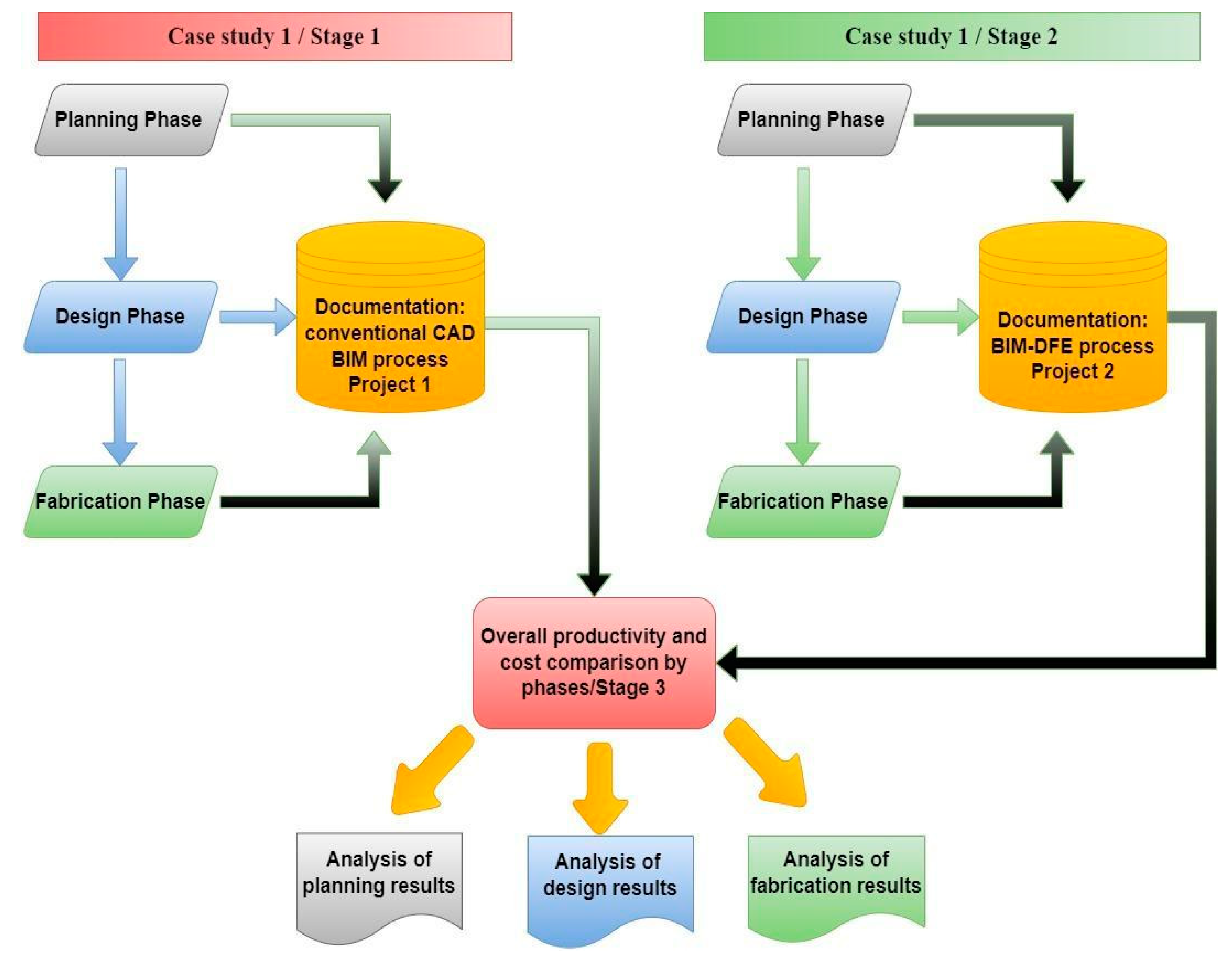
The objective of a case study is to identify the relationship between the causes and effects of conditions applied in a certain process and to replicate the advantages in similar processes [44]. The data collected from the selected projects are used to conduct a comparative analysis of the costs and benefits [45] of the BIM-DFE integration methodology in the planning, design, and manufacturing phases of steel construction projects. The following workflow was applied in this study: (1) documentation of the processes in Project 1 (case study 1) using the traditional CAD-BIM methodology; (2) documentation of the processes in Project 2 (case study 2) using the BIM-DFE integration methodology; and (3) comparison of the overall productivity of different phases. The research workflow is shown in Figure 1.
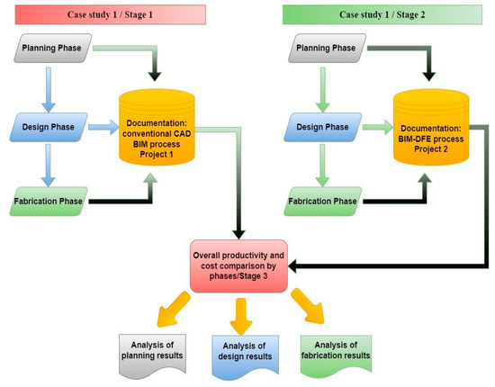
Figure 1.
Outline of the methodology.
2.1. Process Comparison and Scope of Analyses
Two cases were compared in the quantitative analyses of the BIM-DFE method. A follow-up analysis was conducted on two actual steel construction projects during the planning, design, and manufacturing phases. In Project 1, the conventional CAD-BIM integration methodology was applied in the planning and design phases. In Project 2, the BIM-DFE integration methodology was applied, considering its early integration in the planning phase and the modeling tools validated by steel industry experts as fundamental to integration.
To conduct an accurate quantitative comparison, projects with a similar typology and function were commissioned by the same client for the same teams (i.e., planner, designer, engineer, and manufacturer). The team categorized the difficulty level both projects as 6 on a scale of 1–10. This was used to reduce the variables that could affect the results of the study (Table 1). The quantification of time allocation in each project was obtained through the documentation of daily activities performed by workers. This record provided precise data regarding the hours assigned to individual workers for each project, focusing primarily on the planning and design phase. In the subsequent fabrication phase, a log of daily productivity was maintained, encompassing the recorded hours of machinery and workstation utilization dedicated to each project. Furthermore, this log was complemented with the registration of tonnage allocated to each workstation, facilitating the calculation of production output in terms of tons per hour for each segmented workstation within each project.

Table 1.
Characteristics of the case study projects.
A company named MIA Ingenieria was responsible for managing the projects located in Buenos Aires, Argentina. In the construction industry, the development and execution times are key indicators of the project performance [23]. Therefore, after the application of the traditional CAD-BIM and BIM-DFE methodologies, the benefits were quantified based on the average time required to perform each of the processes in each phase [14,40].
2.2. Case Study 1
The approach to case study 1 is elucidated by employing the CAD-BIM methodology.
2.2.1. Introduction
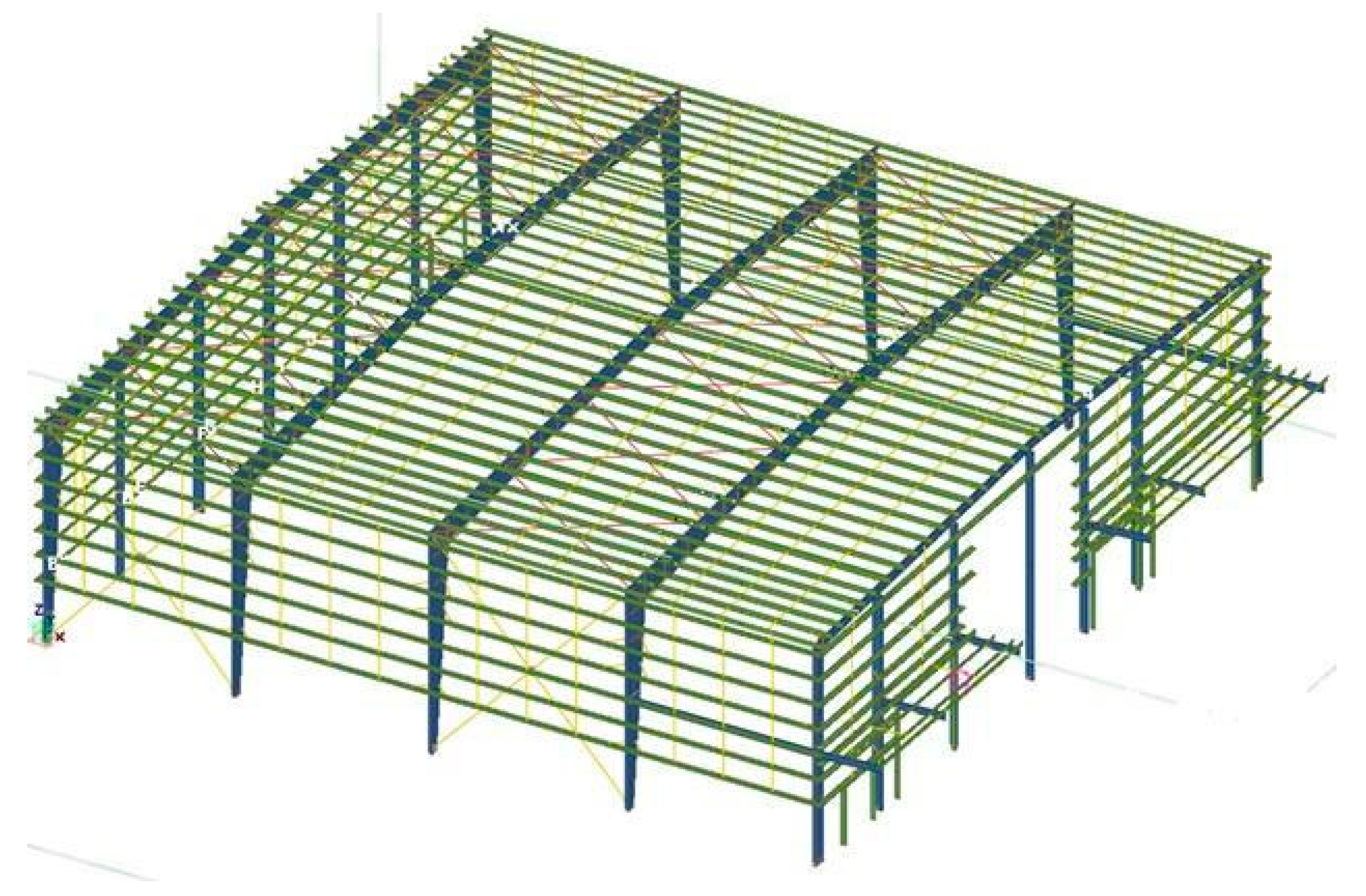
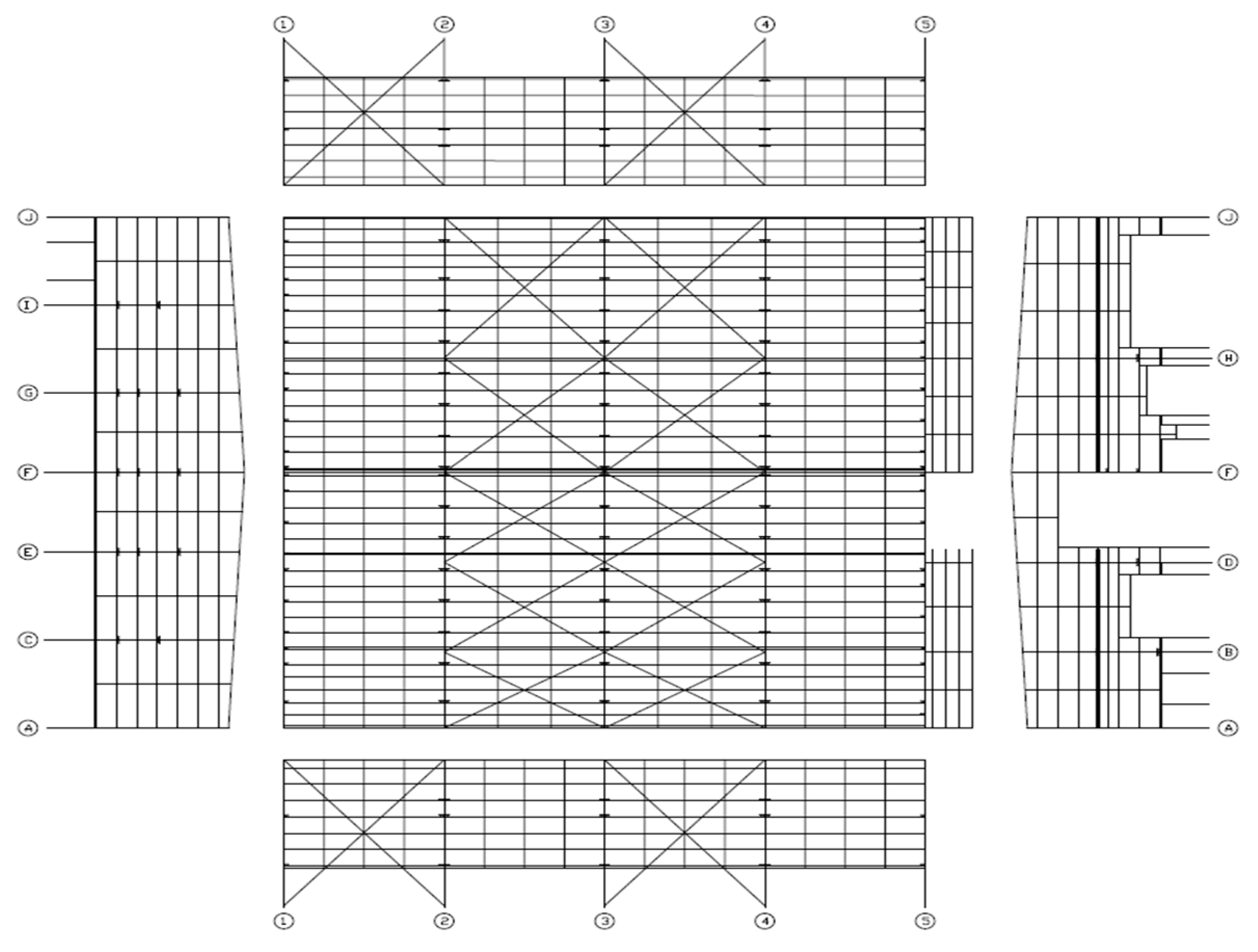
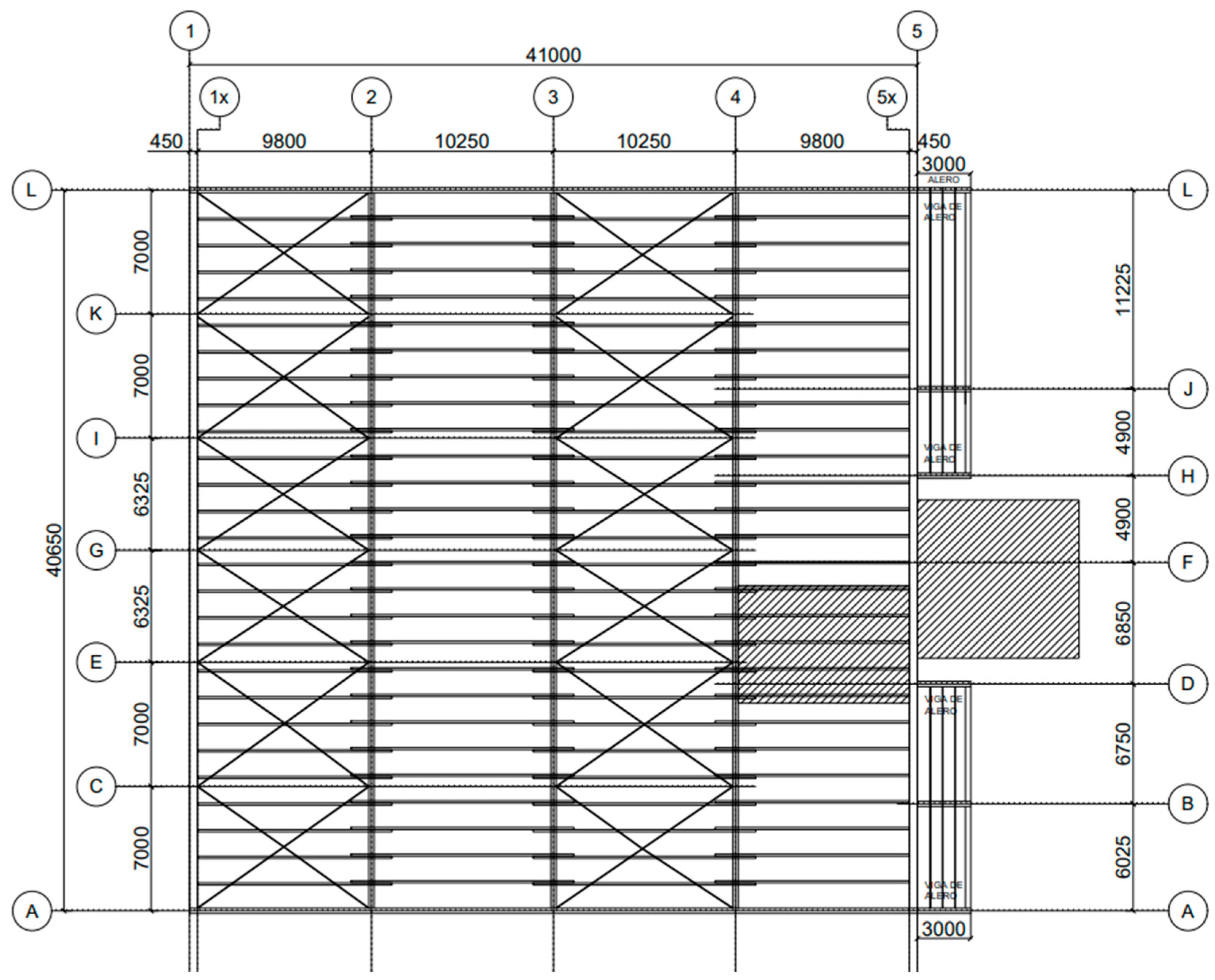
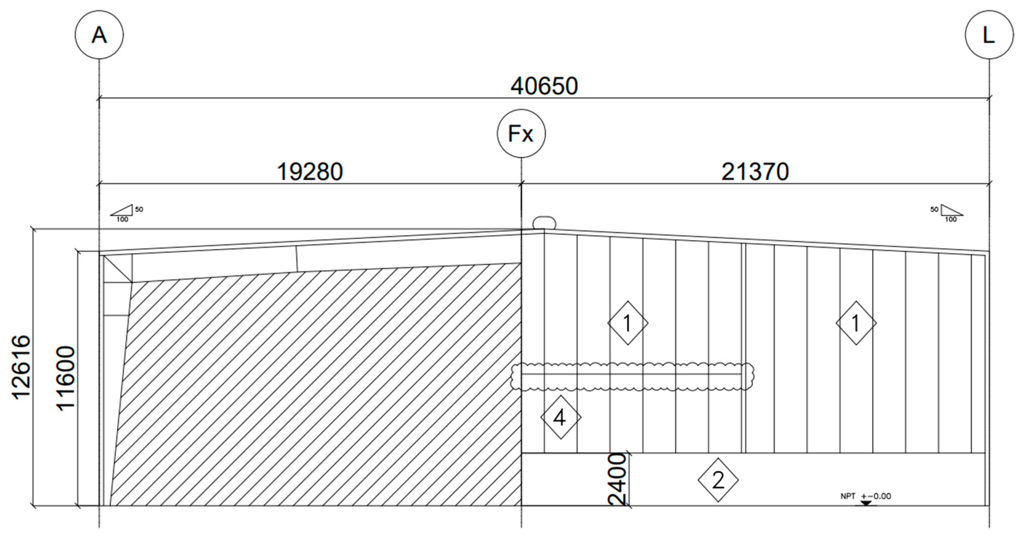
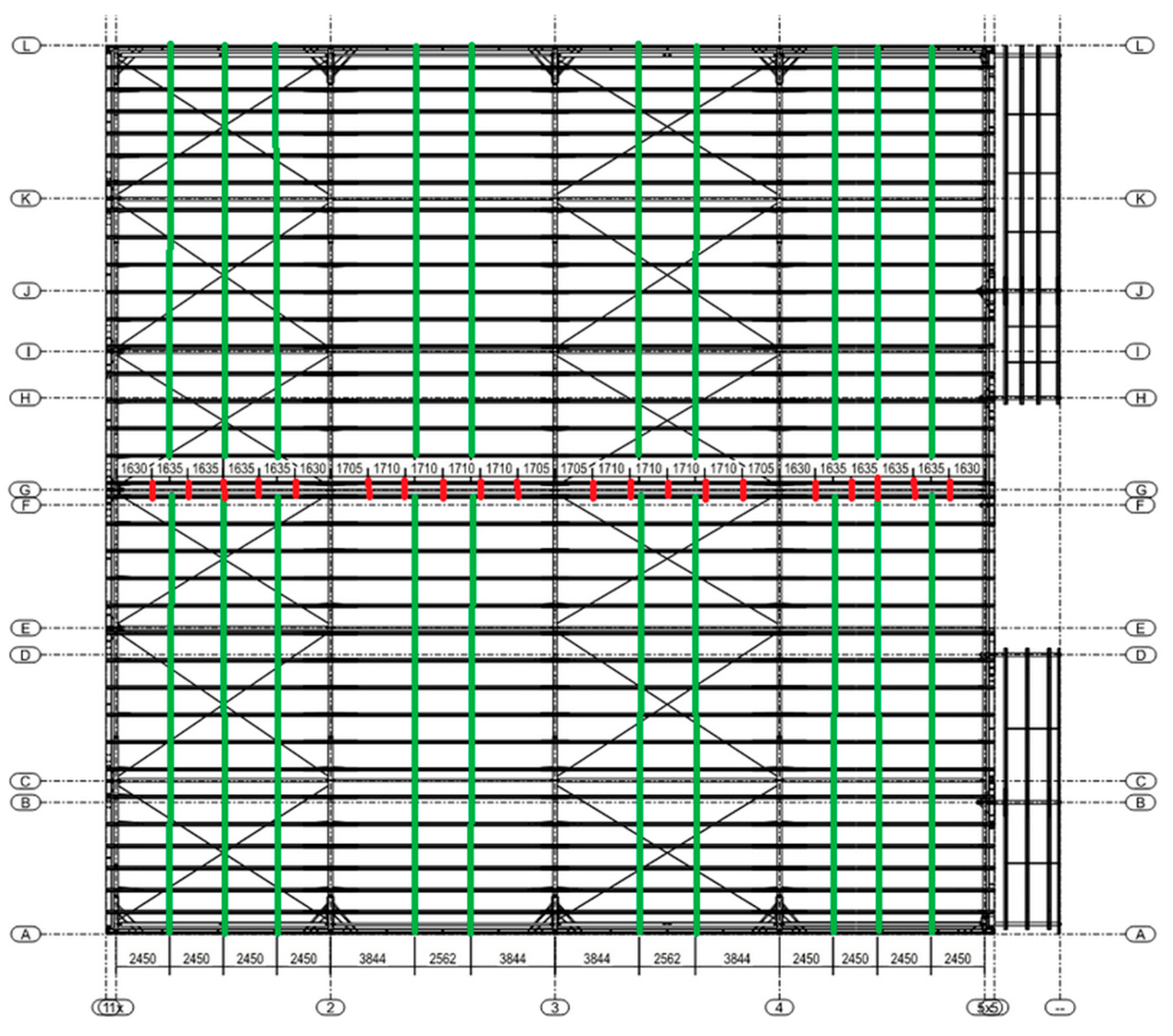
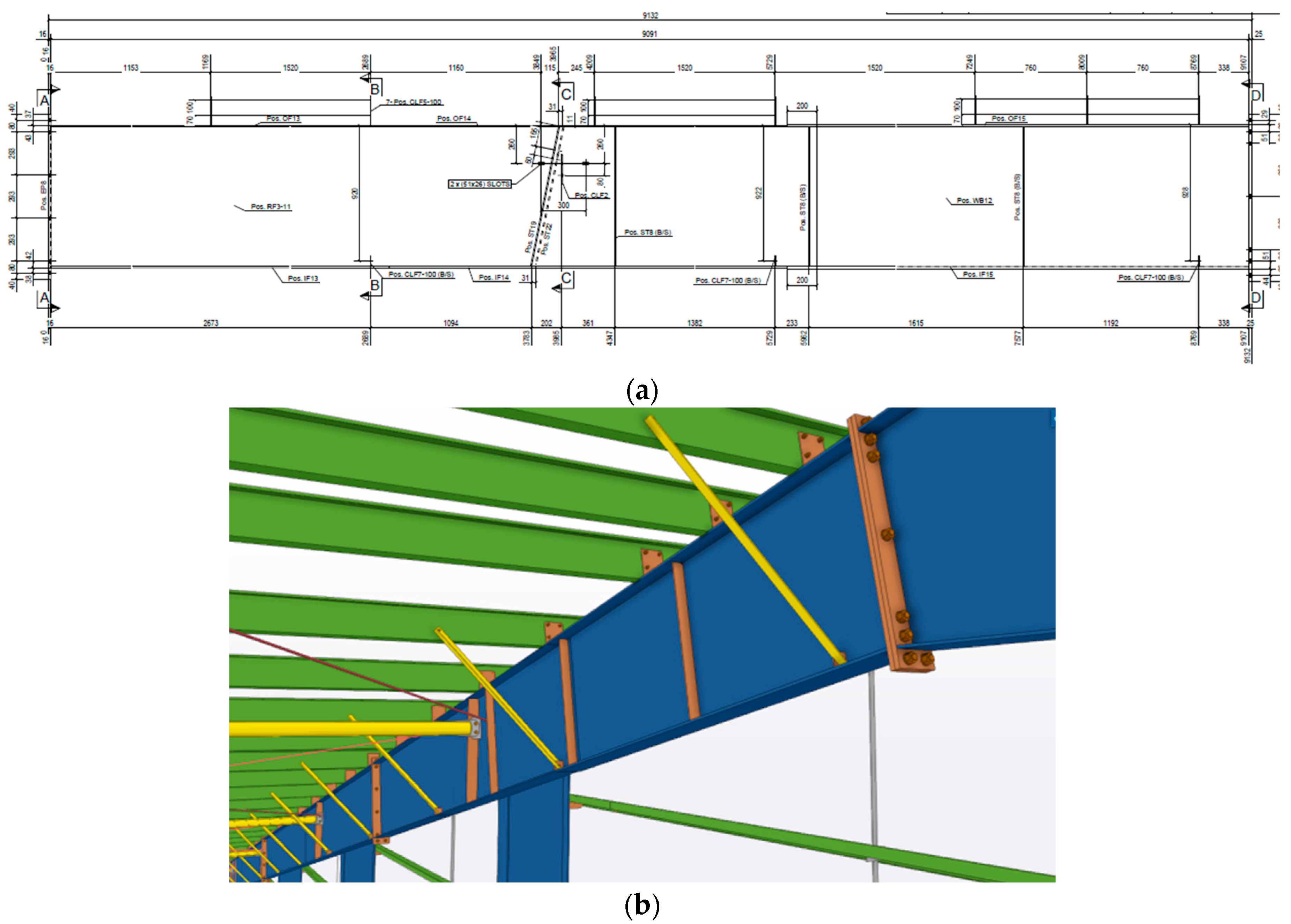
Project 1 encompasses a steel construction featuring a spectrum of structural components, including columns, beams, rafters, vertical and horizontal bracing, walls, and roof rafters (Figure 2). Detailed project characteristics are provided in Table 1.
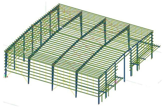
Figure 2.
Details of case study 1.
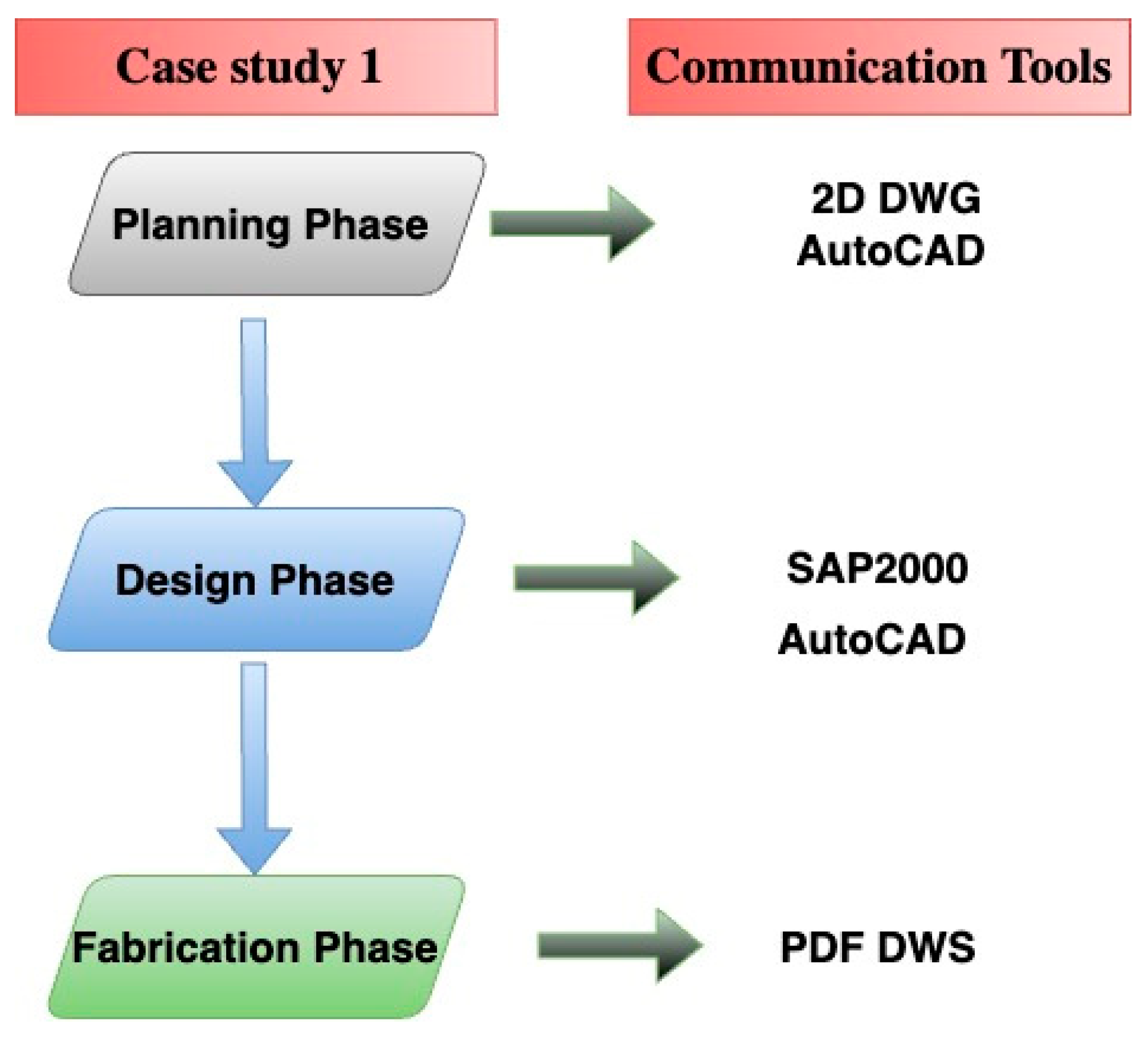
The methodology used in this study was supported by CAD and BIM technologies implemented in the aforementioned phases of the steel structures. AutoCAD 2019 and SAP2000 were used as the tools in case study 1, as shown in Figure 3. The team involved in the planning and design phases includes a project manager who also assumed the roles of the senior designer, a junior engineer, senior draftsman/modeler, and two draftsmen. Engineers were classified as either junior or senior depending on their years of experience: more than 10 years for senior and less than 10 years for junior engineers. They were considered CAD or BIM experts if they had participated in at least 20 steel structure projects that used CAD or BIM as design or planning tools. Table 2 lists the classification of the team members by their role and participation in each stage.

Figure 3.
Description of tools used for case study 1.
Table 2.
Team members in planning and design stages.
2.2.2. Planning Phase (Phase 1)
The roles and responsibilities of the project team are established, and potential risks that could affect the completion of the project are identified. In addition, the project type and designer are selected, the necessary resources are defined, and the decision-making and change management procedures for the entire project are established. In short, the planning phase lays the foundation for the entire project and sets up the framework for success. Each of the subprocesses in the planning phase of Project 1 is detailed as follows.
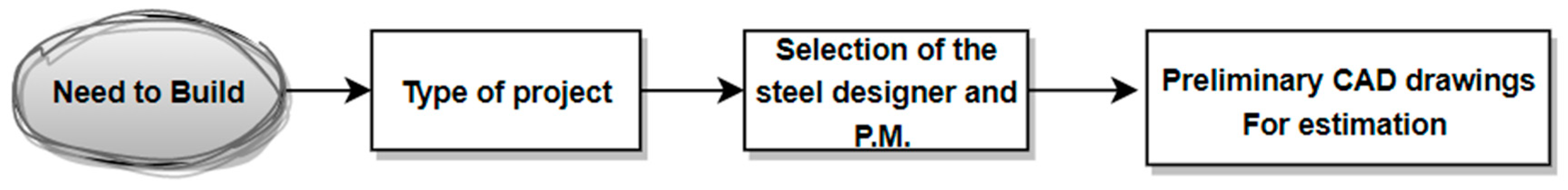
The first subprocess is the intent to build, as shown in Figure 4, which is decided by the client. In this subprocess, the objectives and requirements of the project are established. The feasibility of building the structure in the proposed location is also evaluated by considering factors such as the availability of land, required permits, and capacity to absorb work from the company.

Figure 4.
Planning subprocess (case study 1).
The second subprocess is selecting the type of project that meets the needs of the client and the capabilities of the company being studied. The main objective is to determine whether the project should be industrial or commercial according to the specifications and requirements of the client. Factors such as the project location, and the size, complexity, and end-use of the structure were analyzed. The project type was categorized as industrial. To proceed to the next step, the available resources (e.g., personnel to conduct design and manufacturing) were also considered. Determining the right project type is essential to meet client expectations and ensure project profitability.
The third subprocess is selecting the designer and project manager, which requires a professional with extensive experience in the type of project selected (i.e., industrial projects). This individual must possess skills and knowledge in project management. Choosing the right person for the job is crucial to the success of the project as this individual will be responsible for leading and coordinating the team throughout the project.
The selection process includes evaluating the skills and experience of various candidates within the team. It is important that the designer and project manager have the ability to work with clients to understand their needs, translate these into technical specifications, coordinate the team, and ensure that deadlines and budgets are met.
A designer with experience in industrial projects must be selected because of the need to modify the design to meet the client’s needs. This individual also plays the role of the project manager who ensures coherent and cohesive teamwork.
The fourth subprocess is the preliminary CAD drawing. This involves creating two-dimensional (2D) planimetry to serve as the basis for estimating the number of tons to be processed and, therefore, the final budget of the project. This task is performed by a senior designer, who also assumes the roles of a project manager and senior draftsman who works for 60 and 80 h, respectively, to produce deliverables. Once completed, the planimetry and budget are presented to the client. The delivery of these documents completes the subprocess. Figure 5 shows sample CAD drawings.

Figure 5.
Computer-aided design (CAD) estimation drawings (case study 1).
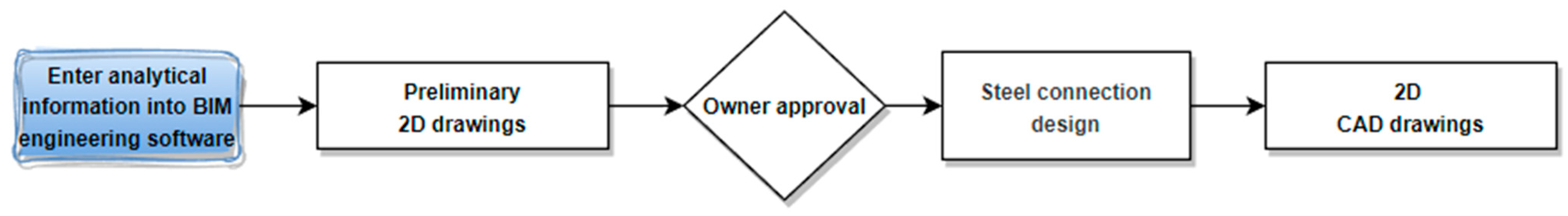
2.2.3. Design Phase
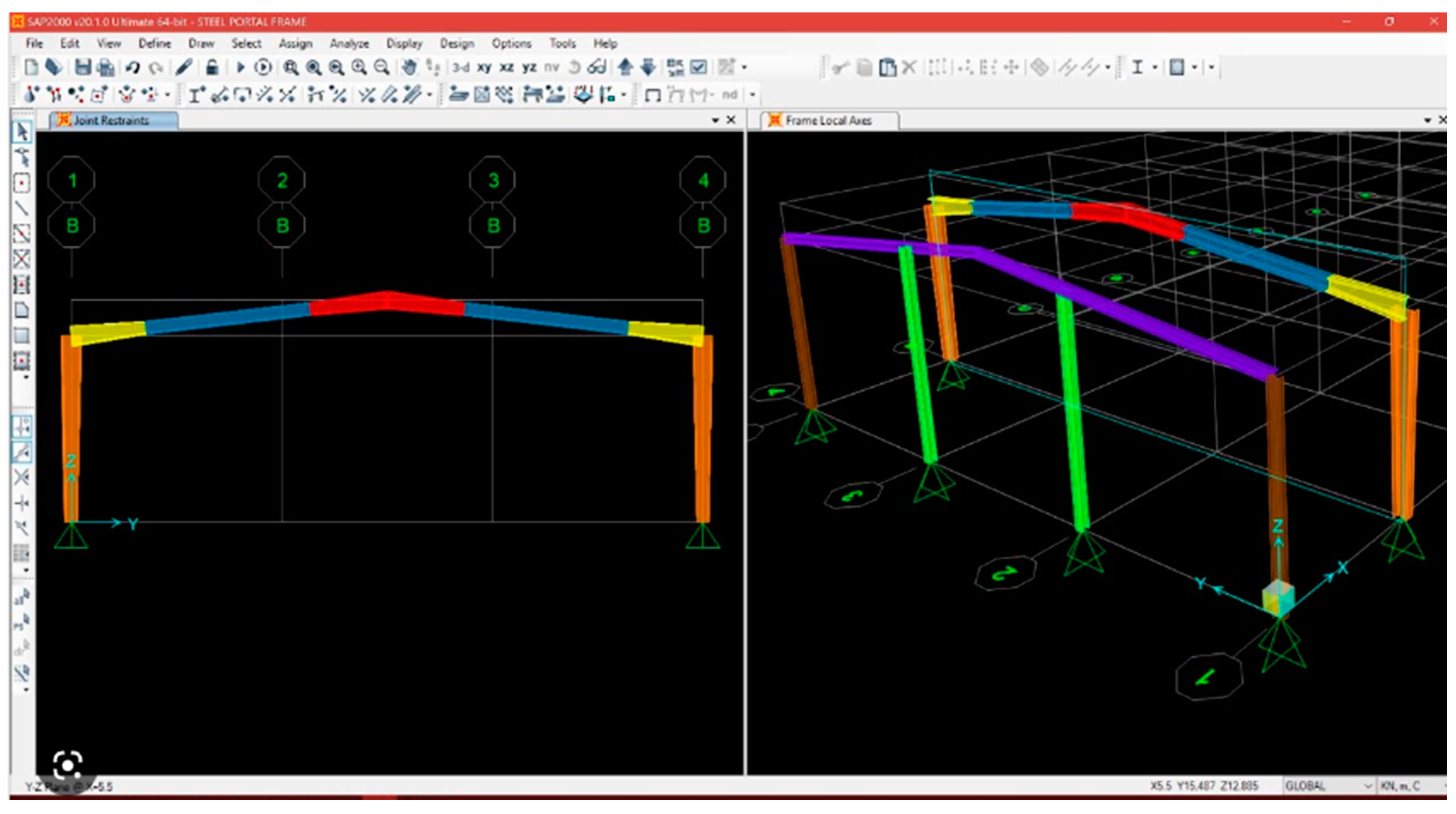
The design phase in case study 1 includes a series of subprocesses, as shown in Figure 6. The first subprocess is the entry of information from the CAD model in the previous phase into the SAP2000 software. The model is used to perform structural engineering calculations to determine the load capacity of the structure. A thorough review of the results was then conducted, followed by the required modifications to the model, including the materials selected and structural specifications. The available options were evaluated, and the section sizes that suit the needs of the project were selected, as indicated by the 3D analytical model in Figure 7. In this subprocess, a senior engineer was required to work for 80 h.
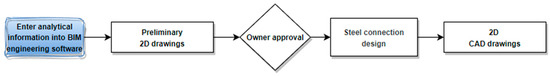
Figure 6.
Design subprocess (case study 1).
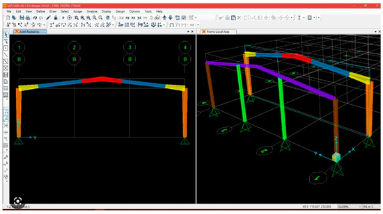
Figure 7.
Three-dimensional analytical model sample (case study 1).
In the second subprocess, 2D preliminary drawings were created by transferring all the graphical designs (2D drawings of floor plans, elevations, and other details) made in AutoCAD (2D), as shown in Figure 8 (preliminary floor plan). This process consumed a total of 100 h: 60 h by the senior draftsman and 40 h by the junior draftsman.
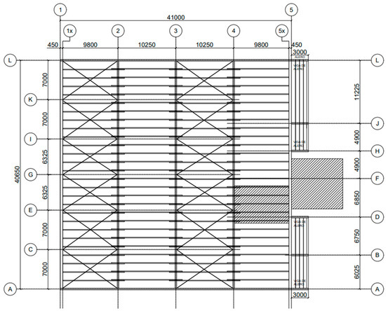
Figure 8.
Two-dimensional preliminary plan (case study 1).
The third subprocess is obtaining the client’s approval of the design. The drawings were initially sent to the client. However, owing to the client’s failure to understand the planimetry interpretation, the drawings were rejected. Thus, the senior engineers had to meet with the client and explain the drawings and present a new proposal.
The second proposal, depicted in Figure 9, was accepted by the client, who also approved the advancement to the next subprocess. This subprocess required a total of 45 and 35 h for engineering and drawing, respectively.
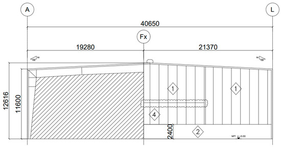
Figure 9.
Modified drawing after client approval (case study 1).
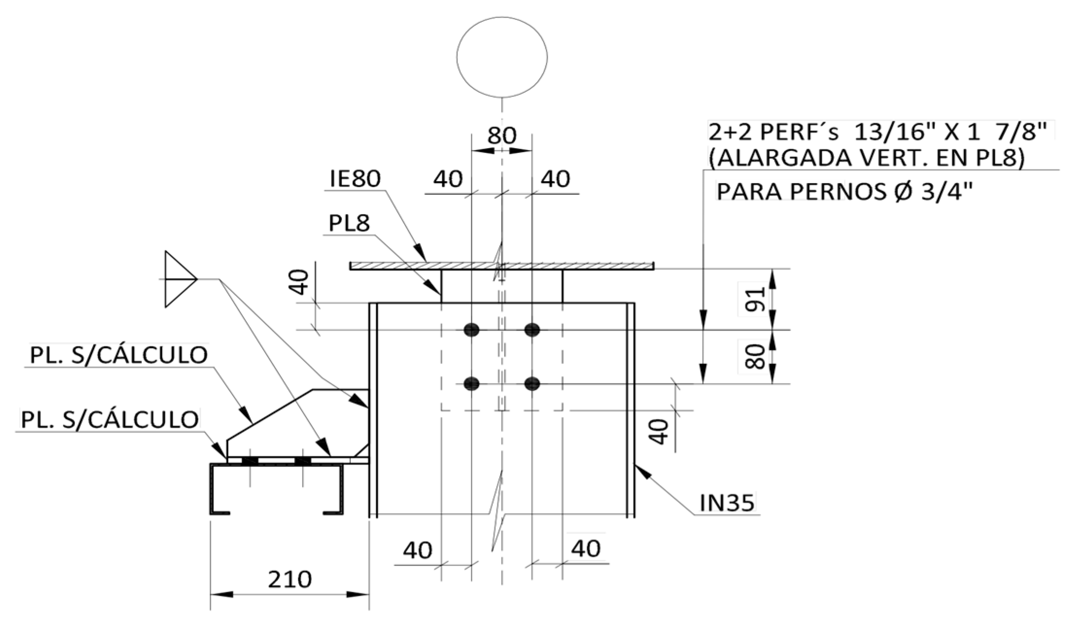
After the client’s approval was received, the next subprocess was to manually calculate the connections, as shown in Figure 6.
The connections per node were calculated, as shown in Figure 10. The completion of this subprocess required 40 h of calculations by a senior engineer, 50 h of work by a junior engineer, and 40 h of assistance by a junior draftsman.

Figure 10.
CAD connection design (case study 1).
The final subprocess in the design phase is generating the 2D CAD drawing, as shown in Figure 6. Information on the steel connections was incorporated together with the floor plans, axis elevations, and other details for the manufacturing process, as shown in Figure 11. This subprocess required 30 h each from the senior and junior draftsmen.
Figure 11.
Sample 2D CAD drawing (case study 1).
2.2.4. Fabrication Phase
Subsequently, the fabrication phase is elucidated according to Figure 12.

Figure 12.
Fabrication subprocess (case study 1).
The team tasked with building the structure in Projects 1 and 2 included an engineering supervisor with 18 years of experience, who managed quality control in the entire fabrication phase from planning to painting, as shown in Figure 12.
The first subprocess is production planning, which was assigned to Engineer 2 with 12 years of experience. In this subprocess, the information obtained in the previous phase was used to make the necessary purchases. The information from the 2D plans was used to estimate the amount of steel required and generate the purchase orders for the raw materials. Engineer 2 was also tasked with extracting the information on raw materials from the 2D drawings, which took 40 h. This is the first subprocess in the fabrication phase, as shown in Figure 12.
The second subprocess is nesting, which was performed to optimize the raw materials for the fabrication of the structure. This process was performed using AutoCAD, which required an additional 20 h of work from Engineer 2.
The third subprocess is material preparation, which was performed by two operators who transferred information from the previous subprocess, i.e., from “Nesting”, to the computer numerical control (CNC) plasma (Figure 13), which was used to cut the plates for processing. The operators were also tasked with cutting, roughing, chamfering, and drilling the subcomponents of the structural assemblies. This subprocess involved two factory operators who worked an average of 2.5 h/t.
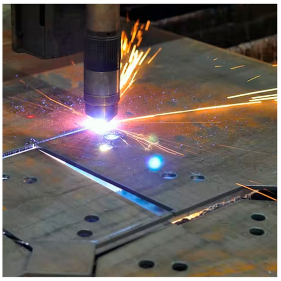
Figure 13.
Material preparation using computer numerical control (CNC) plasma (case study 1).
The fourth subprocess is assembly and welding (Figure 12), in which parts from the previous stage were gathered at a specific location with sufficient space to present the parts and with only a small weld bead provided, as shown in Figure 14. Finally, the assembled components were welded, which required an average of 9.5 h/t.
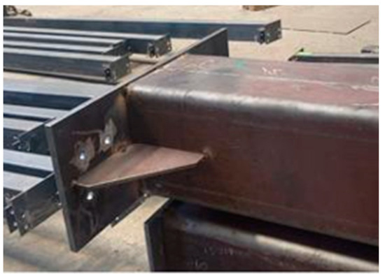
Figure 14.
Preassembly.
The final subprocess is painting, which was applied according to the specifications. Two workers were tasked with painting and cleaning the residues, which took 0.5 h/t.
Table 3 presents a detailed breakdown of the subprocesses in the fabrication phase. These include production planning, nesting, material preparation, assembly and welding, and painting. The table also lists the professionals responsible for overseeing and ensuring the quality of each subprocess, and the technical staff who execute each task. The comprehensive breakdown of each subprocess provides a thorough understanding of the fabrication phase and a clear framework for its execution.
Table 3.
Details of subprocesses and personnel involved in the manufacturing subprocess.
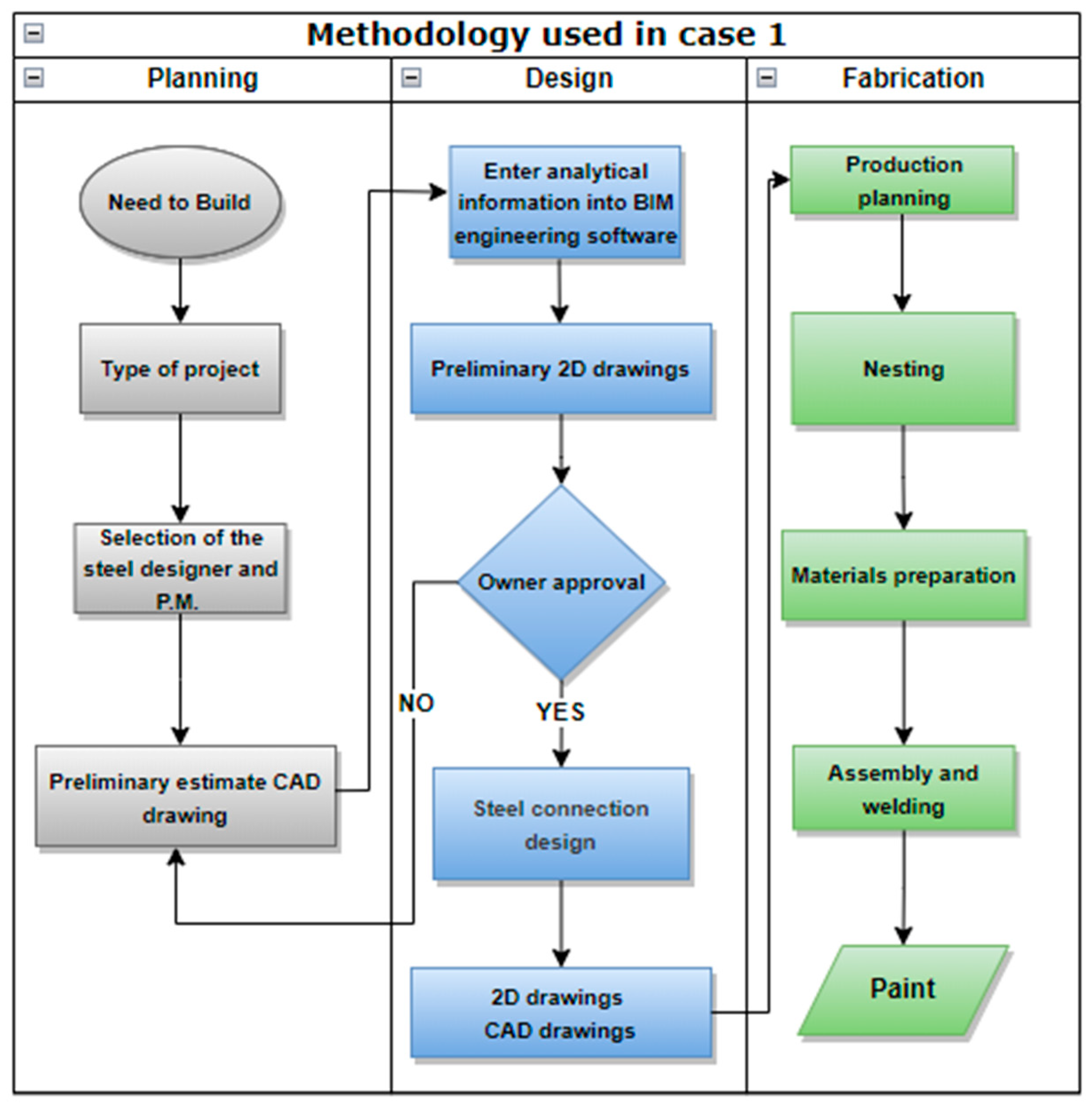
Figure 15 displays a flowchart of the CAD-BIM methodology used in case study 1, which consists of three phases (planning, design, and fabrication) and their corresponding subprocesses. The flowchart includes a breakdown of the subprocesses, such as material preparation, assembly and welding, and painting. The methodology employed provides a visual representation of the different tasks and personnel involved in each phase.

Figure 15.
Flowchart of the CAD-BIM methodology used in case study 1.
In case study 1, significant challenges were identified across different project stages. During the planning phase, difficulties arose in coordinating and allocating resources. In the design stage, insufficient communication with the client and a lack of optimization in the analysis model became evident. Additionally, in the fabrication phase, the lack of connectivity between CAD plans and CNC machinery posed challenges.
2.3. Case Study 2: BIM-DFE Application
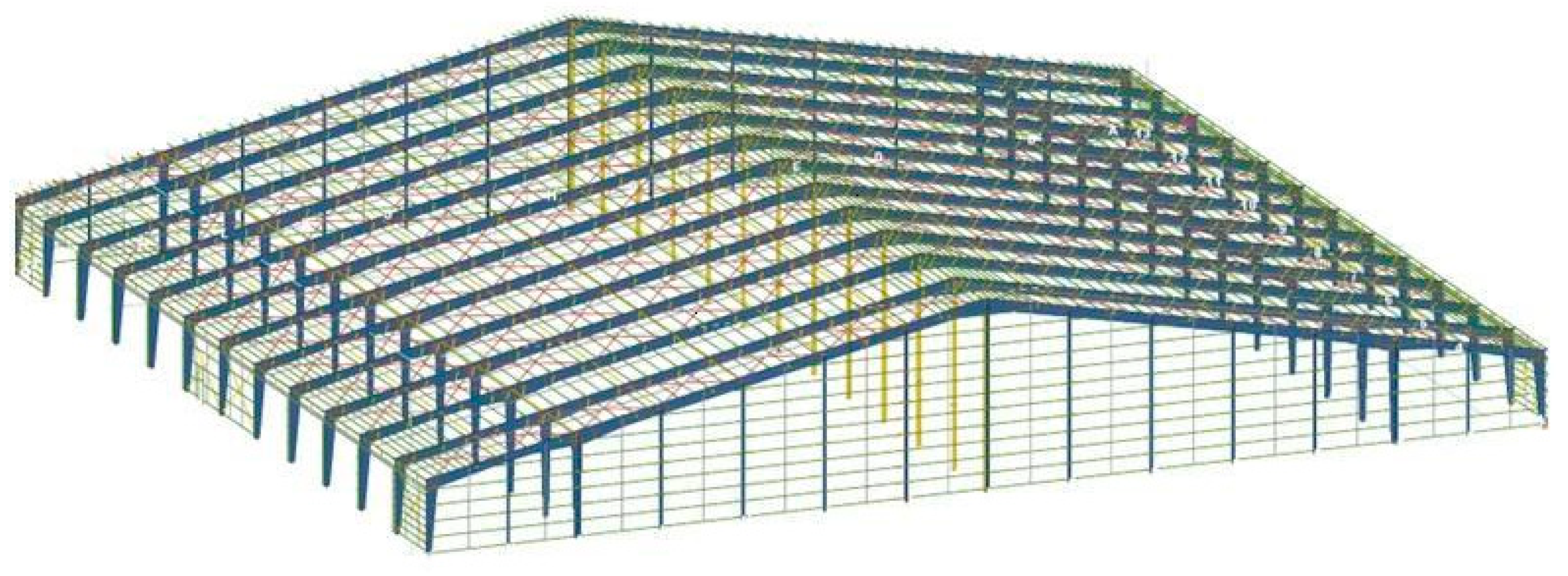
Project 2 encompasses a steel construction, showcasing a range of structural components similar to Project 1 (Figure 16). Detailed project characteristics are provided in Table 1.
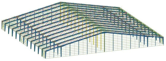
Figure 16.
Isometric case study 2.
The BIM-DFE methodology was applied in all three phases. The tools used were Tekla, SAP2000, and RISA [9], as shown in Figure 17. The team that developed the project during the planning and design phases included the project manager, who also fulfilled the role of senior designer; one junior engineer, one senior draftsman/modeler, and two detail draftsmen. The classification of juniors and seniors was based on years of experience. Individuals with over 10 years of experience were classified as seniors, while those with less than 10 years were juniors. Finally, they were classified as CAD or BIM based on their participation in at least 20 steel construction projects that used CAD or BIM as design or planning tools. Table 2 lists the team members according to their roles and participation in each phase.
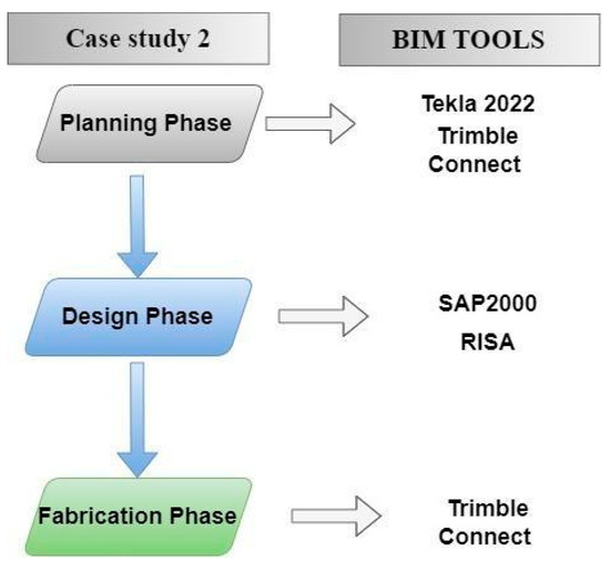
Figure 17.
Description of tools used for case study 2.
2.3.1. Planning Phase for Case Study 2
In case study 2, similar to case study 1, the project began with the client’s intention to build the structure, followed by the identification of the project type; in this case an industrial project. Then, the designer was selected to play the role of the project manager and provide the client with technical assistance throughout the project.
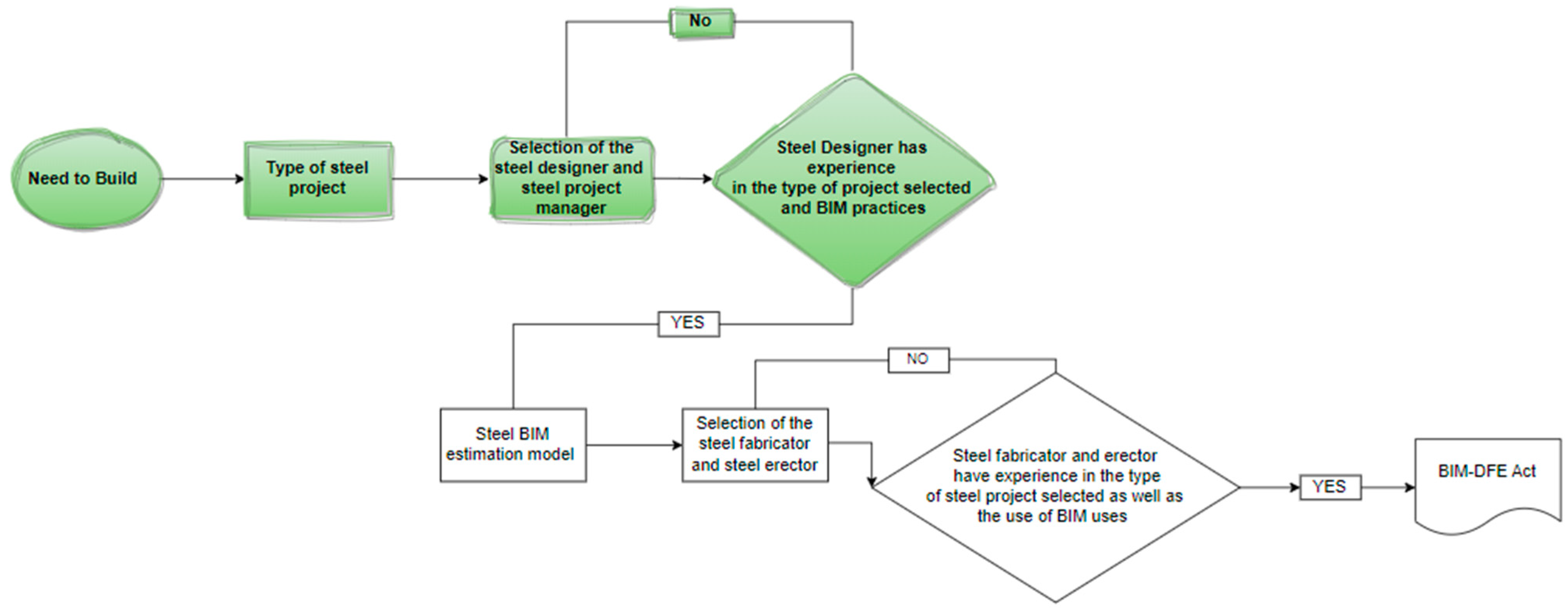
A key element of the BIM-DFE approach is the careful selection of the team that will implement the project based on their experience in the type of project selected and the use of BIM models for steel structures, as indicated in Table 2. Accordingly, a thorough search was conducted for the designer who would interact with the client Figure 18. The designer was required to have at least five years of experience in industrial projects and should have managed at least 10 projects using BIM.
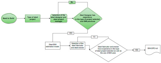
Figure 18.
Planning processes for case study 2.
BIM Estimation
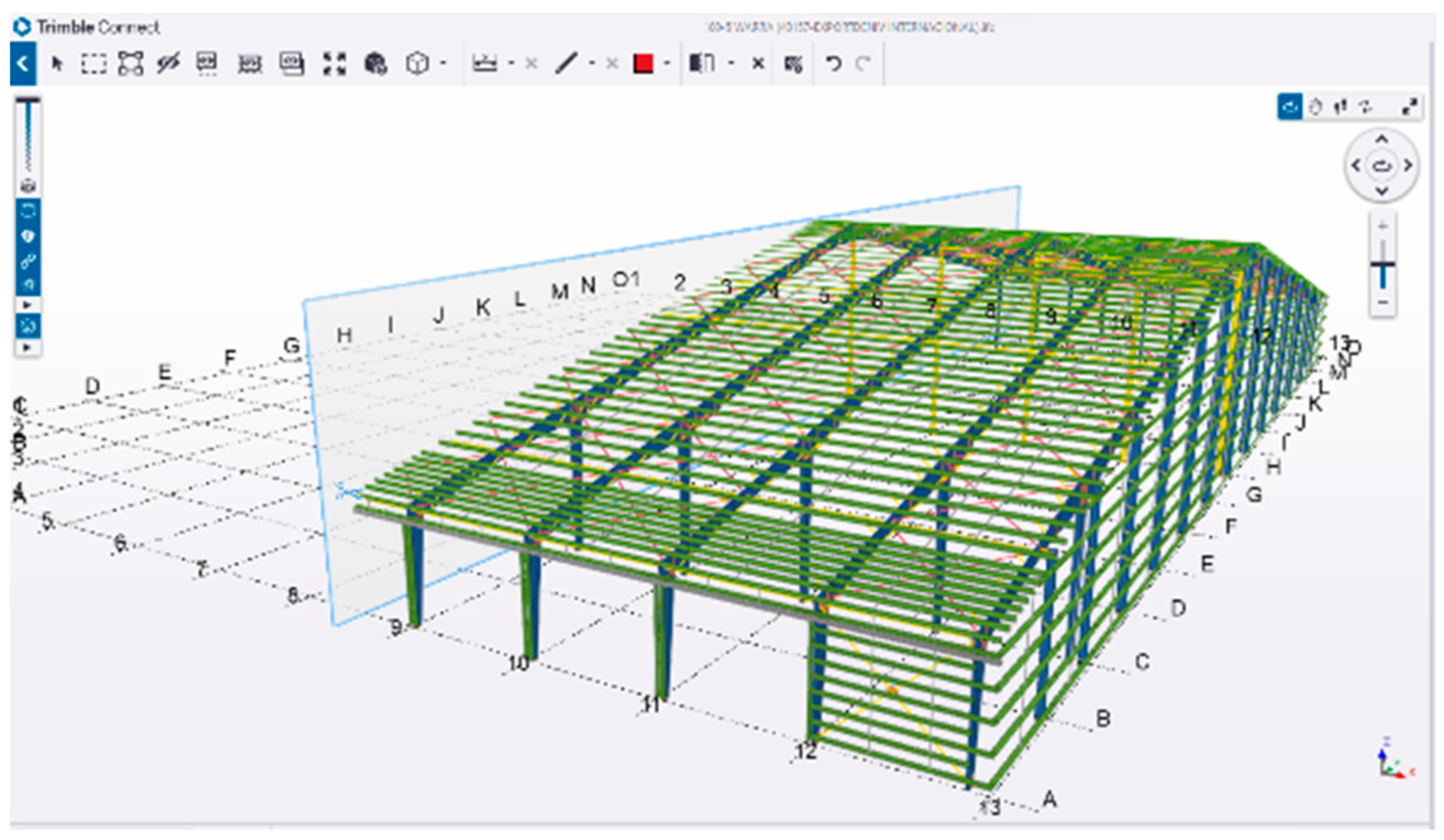
In the planning phase of the project, the subprocess of developing the BIM estimation model was conducted using the Tekla Structure 2022 tool. The main objective is to determine the geometric scope of the project in collaboration with the client to avoid wasting time on this task once the calculations for the structure were completed. The BIM estimation model made it possible to accurately determine the amount of steel to be manufactured and assembled, thereby accelerating quotations from the manufacturers, transporters, and assemblers. In the implementation of the estimation model, the model created in Tekla Structure was exported in the IFC format and uploaded to Trimble Connect, a platform used to share and review BIM models online. To perform this task, the model was shared with the client via email, allowing an online review in a remote meeting. Trimble Connect enables the visualization and review of the model in real-time, allowing interaction between the client and engineer in charge of the estimation model despite their different geographical locations. The experience of the engineer in charge of the estimation model led to the smooth implementation of this technological tool, facilitating the review and approval of the model by the client, as shown in Figure 19. The review of the estimation model with the client resulted in minor changes, which were incorporated into the model. The estimation model was developed by a senior engineer who dedicated 40 h to its creation, eliminating the need for draftsmen. This subprocess is shown in Figure 18. It should be noted that the use of BIM estimation improved the efficiency in estimating the amount of steel to be processed and reduced the risk of errors in the final budget of the project.
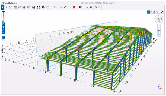
Figure 19.
BIM estimation model.
Selection of the Steel Fabricator
In-line with the BIM-DFE methodology, manufacturer selection is crucial to the successful execution of the project. An experienced manufacturer is required, i.e., with experience in industrial projects and the ability to utilize the BIM model from the early stages of the project. Therefore, it is important to consider the following characteristics in manufacturer selection.
First, the fabricator must have CNC machinery that allows the nesting of steel components to be fabricated in the material preparation subprocess to facilitate the optimization of resources and reduce production times.
Second, the fabricator must have a manufacturing-enterprise resource planning (MERP) software to manage the purchasing of raw materials to be manufactured using the nesting process in the BIM model. This allows more efficient management of the purchasing process and reduces the time required for raw material acquisition. In such cases, STRUMIS software can be used.
Third, production control that can be applied in Trimble Connect or in the same MERP is required to ensure the transparency of the manufacturing process for the benefit of stakeholders. This improves the control and monitoring of the production process.
Finally, the Tekla model is expected to be used by manufacturing inspectors as well as assembly and welding operators to facilitate their understanding of the geometry of various assemblies. This allows for more accurate and efficient execution of the project.
In summary, manufacturer selection is critical to the successful application of the BIM-DFE methodology. It is important to find a manufacturer with the aforementioned characteristics to ensure the efficient and effective management of the project using the BIM-DFE methodology.
BIM-DFE ACT
To finalize the estimation process using the BIM-DFE methodology, a BIM-DFE ACT report was generated (Figure 18), which identifies the following characteristics of the planning process:
All parts and components of the project were modeled according to the requirements of the client, considering the restrictions of the geographical location of the project. All the necessary information for cost estimation and control were included, such as the quantity and type of materials, and the location and quantity of components.
The model was shared with the project manager and client for review and feedback.
The manufacturer selected for the application of the BIM-DFE methodology has the following characteristics:
- Experience in the type of project selected, i.e., industrial projects;
- CNC machinery for the preparation of the material and a MERP to manage the purchase of raw materials;
- Transparent production control that discloses the progress of the manufacturing process to other stakeholders;
- Use of the Tekla model to facilitate the understanding of the geometry of different assemblies by the manufacturing inspectors and assembly and welding operators.
Finally, the estimation process was completed in 40 h by a senior engineer.
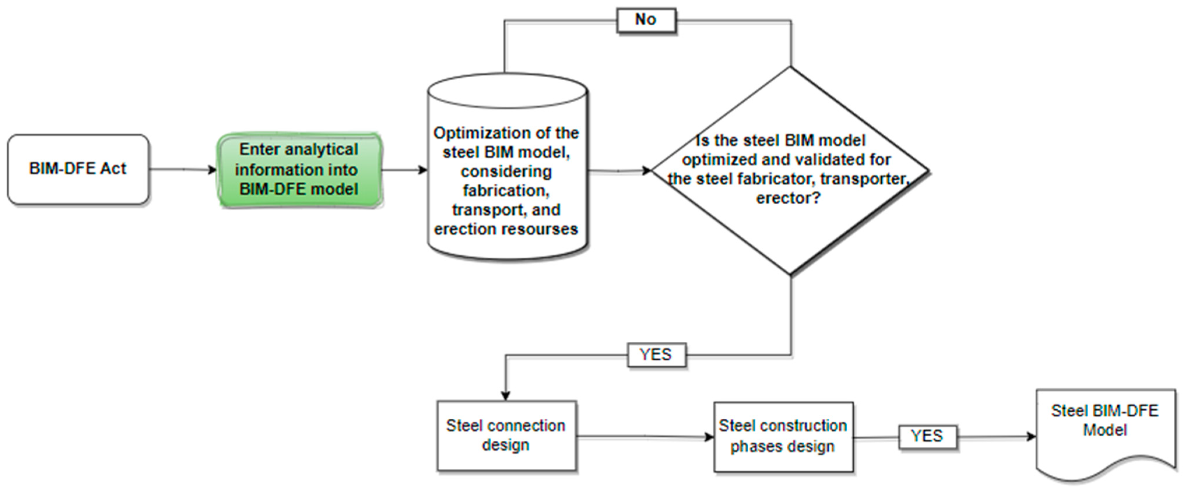
2.3.2. Design Phase Using BIM-DFE
Analytical Information Input into the BIM-DFE Model
The first subprocess in the design phase is to input the analytical information into the BIM-DFE model, as shown in Figure 20.
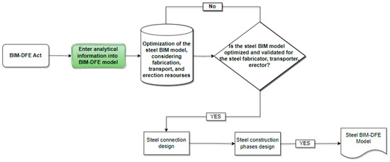
Figure 20.
Design process for case study 2.
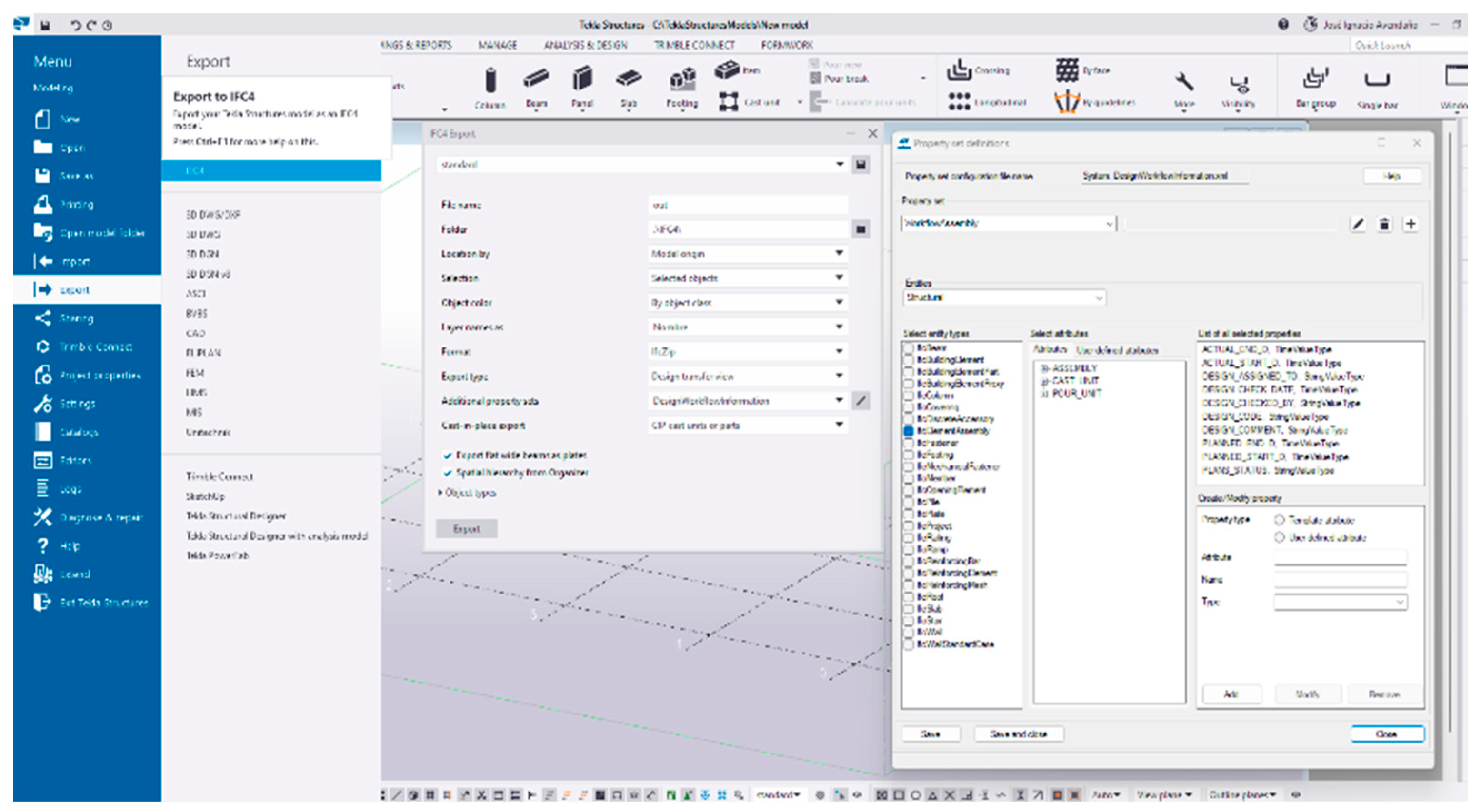
Interoperability between the design and structural analysis software is essential to ensure the efficiency and accuracy of the analytical model. In this regard, the IFC Tekla model from the previous stage was proven to be a significantly useful tool for the transfer of information between project planning and its analysis and design, as shown in Figure 21.

Figure 21.
IFC configuration from the Tekla structure.
The transfer of IFC models between Tekla and SAP2000 for the load analysis was highly beneficial. This was achieved by satisfying certain characteristics of the model, such as precision, consistency, data hierarchy, clear identification of components, and detailed properties of the components in the estimation stage. These requirements ensured that the model transferred from the estimation to the design stage is complete, accurate, and easy to analyze.
In SAP2000, a complete structural analysis was performed to verify the wind, snow, and earthquake loads along with the live and dead loads of the structure, while considering the geographical location of the project. Local design codes and standards were considered to ensure that the structure met safety and regulatory requirements.
Figure 22 shows the model analyzed in SAP2000 to ensure that the structure is safe and meets the design requirements.
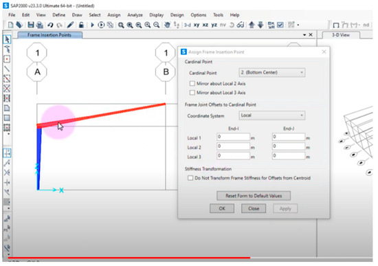
Figure 22.
Sample analysis of model in SAP2000.
The analysis in SAP2000 allowed the engineer/project manager to optimize the structure to meet the security and efficiency requirements. Design changes were made to meet the load requirements without compromising the integrity or undermining the original design approved by the client. This subprocess required 20 h from the engineer/project manager.
Optimization of the Steel Structure
Once the structural model was validated in the design and analysis stage using SAP2000, it was optimized by considering the manufacturer resources, as shown in Figure 20.
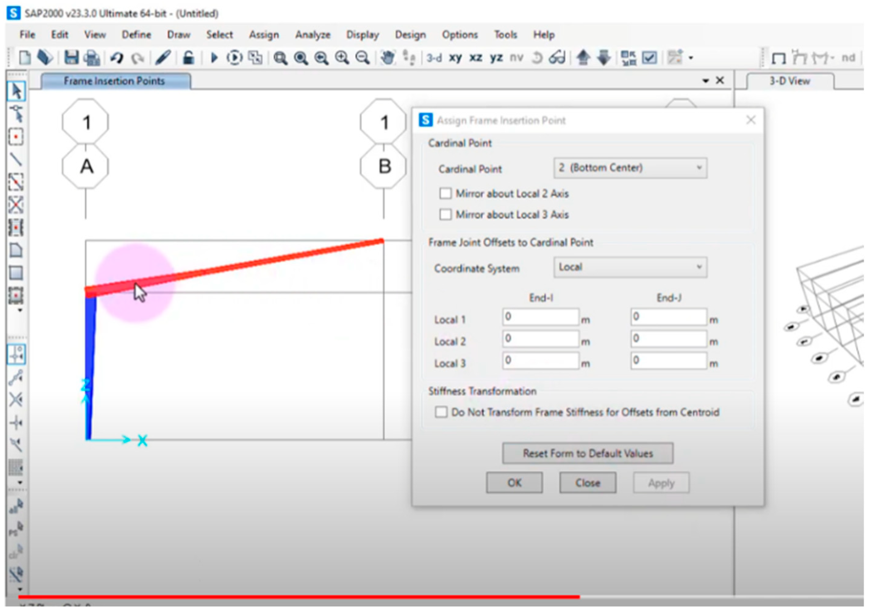
This was achieved by exporting the model from SAP2000 to Tekla in the IFC format, as shown in Figure 23.
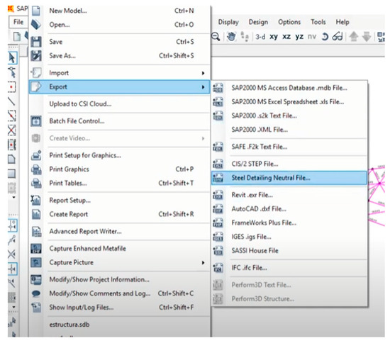
Figure 23.
SAP2000 export to Tekla structure by Steel-Detailing Neutral File.
Subsequently, the factory manager (manufacturing) was asked to validate the Tekla model along with the engineer and project manager. The length restrictions of the materials to be processed and optimization of factory resources were considered. In this process, engineer and project manager spent 12 h, while the senior manager (manufacturing) spent 8 h, for a total of 20 h. A Tekla model optimized for the factory characteristics was obtained, as shown in Figure 24.
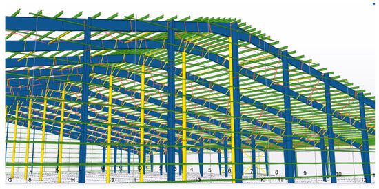
Figure 24.
Optimized Tekla model.
The validation and optimization of the Tekla model allowed the identification of potential problems and optimization of the manufacturing process. Because of the collaboration between the engineers and senior manufacturing managers, the Tekla model remained within the factory constraints, thus improving the efficiency of the manufacturing process. This process also allowed structural engineers and fabricators to collaborate in the optimization of the structural model, resulting in a more efficient and accurate final structure.
Steel Connection Design
After optimizing the Tekla model for manufacturing the structural components, the structural connections were validated and the fabrication phases identified (Figure 20).
The tool used was the RISA 3D software. The information transfer between Tekla and RISA 3D was performed by extending RISA 3D to Tekla, as shown in Figure 25.
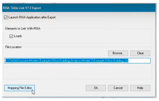
Figure 25.
Steel connection import and export to and from RISA 3D.
The validation of structural connections is a critical process in structural design because such connections are subjected to the highest stress and could be the most vulnerable to failure if designed incorrectly. In other words, the connections must be validated to ensure the safety and efficiency of the structure.
In this process, the senior engineer/project manager is in charge of validating the structural connections using the RISA 3D software. The connections were validated for 10 h, during which they were thoroughly checked to ensure that they meet safety and efficiency requirements.
The validation of structural connections ensures their integrity and their adequate design and dimensions to support the applied loads and forces. Finally, in collaboration with the manufacturing manager, the manufacturing phases and sequences were established with the aim of prioritizing the production of structural components according to the factory constraints. At this point, the 3D model had a level of detail (LOD) of 400. This process made it possible to identify production bottlenecks and determine preventive and corrective measures to ensure the efficiency of the manufacturing process and compliance with established deadlines. Collaboration between the structural engineers and manufacturing manager was essential to the success of this process as it allowed the optimization of the manufacturing process and reduction of costs and delivery durations. These steps required a total of 25 h, i.e., 15 h and 10 h from the senior designer and manufacturing manager, respectively.
2.3.3. Steel Construction/Fabrication Phase
After the design and analysis processes were completed, a 3D BIM of the steel structure was obtained. This model contained detailed information on the geometry, loads, and properties of the structural components, making it an accurate virtual representation of the actual structure. The model also contained information on the construction sequence and manufacturing phases for their efficient planning.
The steel BIM was enriched with additional information, such as the manufacturer and supplier information, material specifications, and data on the manufacturing equipment used. Integrating this information into the BIM facilitates a higher level of collaboration between engineers and fabricators, resulting in a more efficient and accurate structure.
In summary, the 3D BIM-DFE model of the steel structure provides a detailed representation of the structure and the required fabrication processes. This information is essential to begin the next phase of manufacturing and ensure an efficient and accurate building process.
Steel Detailing Using the BIM Model for Case Study 2
In the fabrication phase, the BIM-DFE methodology establishes guidelines for starting the fabrication process with the steel BIM-DFE from the previous phase, as shown in Figure 26. This BIM has an LOD 400, which is rich in engineering information, prioritization, and fabrication phases. This allows the model to guide the fabrication process to ensure that the technical specifications and structural design requirements are satisfied.
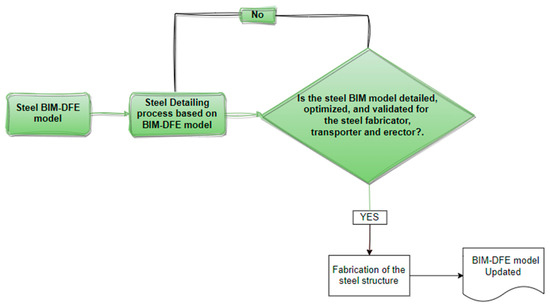
Figure 26.
Fabrication phase for case study 2.
The steel-detailing process generates the plans for the production of the structural components. Performed using specialized Tekla software, it generates detailed information on structural components such as cuts, perforations, and welds, and extracts dimensions automatically generated by the Tekla model based on information from the previous design phase, Figure 27.
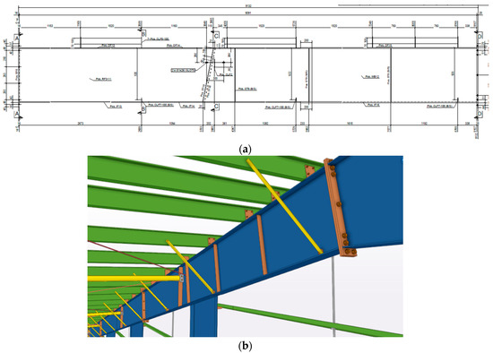
Figure 27.
Steel-detailing samples (case study 2): (a) 2D beam sample and (b) 3D beam sample.
According to the BIM-DFE methodology, the steel-detailing process must be validated by the fabricator, transporter, and erector. As transportation and erection are beyond the scope of this study, only validation by the fabricator was considered in this engineering stage. However, the BIM-DFE model can be applied to transportation and construction.
In summary, the fabrication phase began with the steel BIM-DFE model, which served as a guide in the first stage of fabrication and ensured that the technical specifications and structural design requirements were met. The steel-detailing process was then conducted to generate the plans for the materialization of the structural components.
Fabrication of the Steel Structure
After the steel-detailing process was completed, the information was transmitted to the factory using the CNC numerical files and planimetry extracted from the detailed model. This information transfer allowed the materialization of the structural components in the factory, which increased the efficiency of the manufacturing process. In addition, nesting of the raw materials was achieved by connecting the Tekla model and MERP STRUMIS. In the fabrication phase, the STRUMIS shop-floor management software was used to plan and monitor the production process of the structural components. The Tekla extension called STRUMIS Integrator was used, which allows the direct transfer of structural information from Tekla to STRUMIS for factory production planning and management (Figure 28a,b).
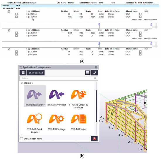
Figure 28.
(a) Nesting process and (b) Tekla STRUMIS information transfer.
The information transferred included the geometry, location, part numbers, quantities, cuts, holes, welds, and other manufacturing details. The STRUMIS Integrator extension also provided feedback from STRUMIS to Tekla to enable the verification and correction of errors in the detailed model.
This information transfer between Tekla and STRUMIS ensured the accuracy and efficiency of the production process and reduced the production time. Moreover, the integration of Tekla and STRUMIS improved the control and monitoring of the production process and reduced errors in the fabrication of structural components.
BIM-DFE Update
During the fabrication process, all the information was shared with the client using the Trimble Connect web-based platform. The Tekla model and information generated during the steel-detailing phase were shared through Trimble Connect. Production, scheduling, and quality control information was shared from STRUMIS through Trimble Connect. Trimble Connect was also used for the real-time collaboration and information exchange between various project participants. Other software options, such as PowerFab or Steel Project, can also be used to share information in the fabrication process.
For the manufacturing process in case study 2, the same team and planning process were used as in case study 1. Engineer 2 worked a total of 2.5 h owing to the automated information transfer from Tekla to STRUMIS, which took 1 h. Nesting generation required 1.5 h to achieve an efficient cutting process. The material preparation rate was maintained at 2.5 h/t, similar to that in case study 1.
For the assembly and welding subprocess, the production rate of 7 h/t optimized the completion time of the manufacturing process. For the entire manufacturing process, the operators had access to tablets that allowed them to clarify any doubts related to the process.
Finally, the painting subprocess had a production rate of 0.4 h/t, which allowed uniform and high-quality paint application. The entire manufacturing process was monitored and shared with the client through Tekla, STRUMIS, and Trimble Connect. These facilitated the fluid and transparent communication between all parties involved, leading to efficient management of the manufacturing process and delivery of a high-quality final product.
3. Results
This section presents the results of the productivity indicator analyses for both case studies. Specifically, the productivity indicators are summarized with a focus on the planning and design phases for case studies 1 and 2. The productivity indicator in the fabrication phase was examined using the classic productivity indicator of hours per ton produced, which is commonly used in the industry [49].
3.1. Case Study 1
The results of case study 1 are presented. The planning phase (Table 4) includes the subprocess “Preliminary CAD Drawings for Estimation”, where only the professionals participated. The design phase (Table 5), where only the senior and junior design professionals participated, includes the following subprocesses: “Enter Analytical Information into the BIM Engineering Software”, “Preliminary 2D Drawings”, “Client Approval”, “Steel Connection Design”, and “2D CAD Drawings”. Finally, in the fabrication phase (Table 6), professionals participated, such as operators. The subprocesses in this phase include “Production Planning”, “Nesting”, “Material Preparation”, “Assembly and Welding”, and “Painting”.
Table 4.
Planning phase.
Table 5.
Design phase.
Table 6.
Fabrication phase.
In case study 1, the average time of fabrication subprocesses such as material preparation, assembly and welding, and painting was 12.5 h/t. This metric provides valuable insights into the time required for these specific fabrication activities per ton of material in the examined project.
3.2. Case Study 2
In case study 2, the same phases were considered as in the first case, but with notable differences in the results and subprocesses. This was attributed to the interoperability, automation, and optimization of the different models in each phase. In the planning phase (Table 7), the “BIM Estimation” and “BIM-DFE Act” subprocesses required only the participation professionals in the project team. In the design phase (Table 8), the subprocesses “Enter Analytical Information into the BIM-DFE”, “Optimization of the Steel Model Process”, and “Steel Connection Design and Phase Identification Process” required the participation of only the professionals with extensive experience. In the fabrication phase (Table 9), the subprocesses were the same as those in the first case, but with a significant difference in productivity owing to the interoperability between the previous phases and the technology used in this phase.
Table 7.
Planning phase.
Table 8.
Design phase.
Table 9.
Fabrication phase.
In case study 2, the average fabrication time was 9.9 h/t of material. This result provides specific insights into the time required for tasks such as material preparation, assembly and welding, and painting.
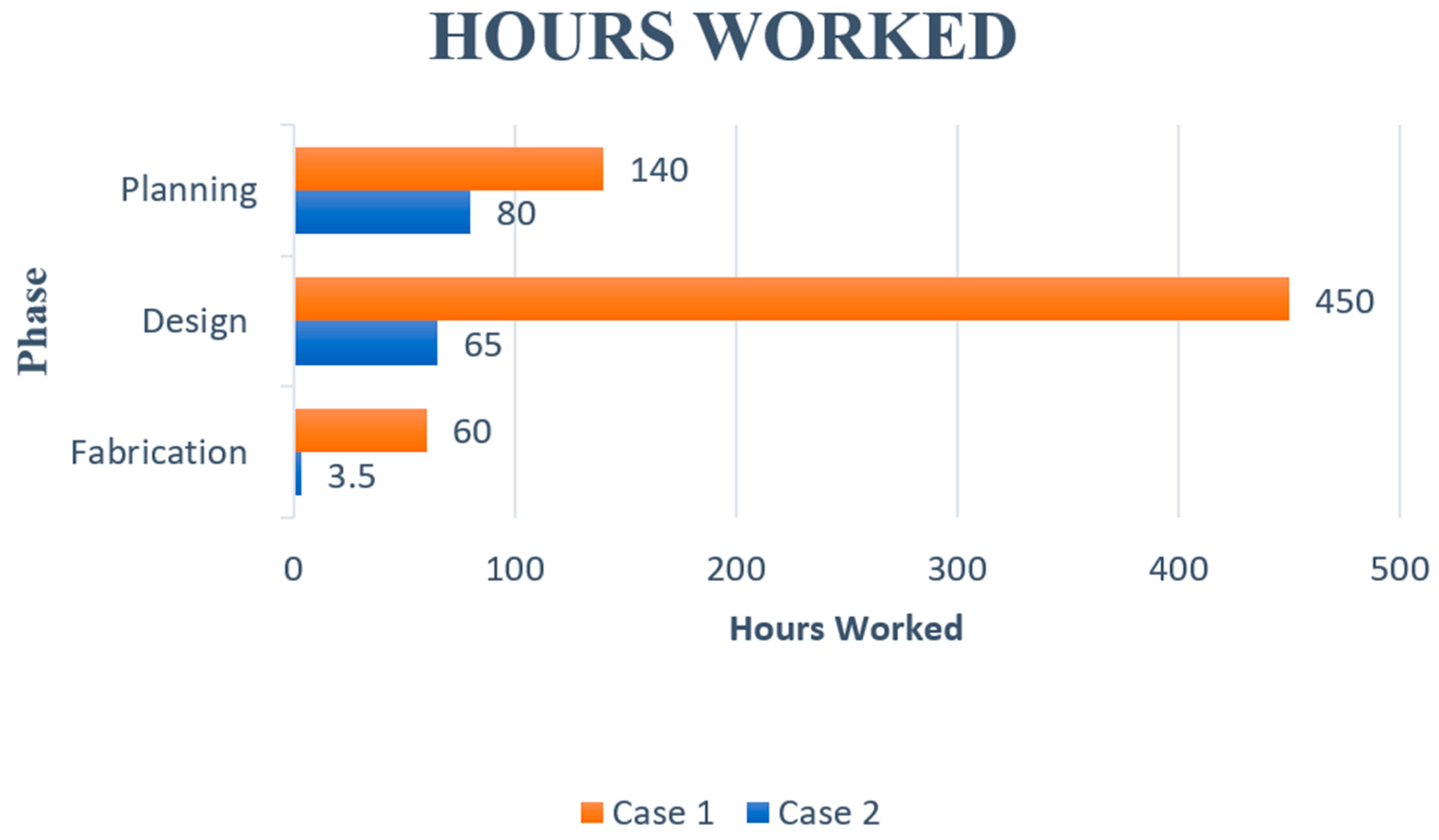
Although the sizes of the studied projects vary, the project typology, steel connections, and complexity are similar. The relevant indicators in this study are the planning, design, and fabrication phases, while transportation and erection were excluded. Figure 29 shows a comparison of the total hours worked in case studies 1 and 2 (engineers and draftsmen). The graph presents the number of hours worked by each professional in the planning, design, and fabrication phases of the project. The total hours worked in case study 2 are significantly lower than those in case study 1.

Figure 29.
Summary of hours by phases.
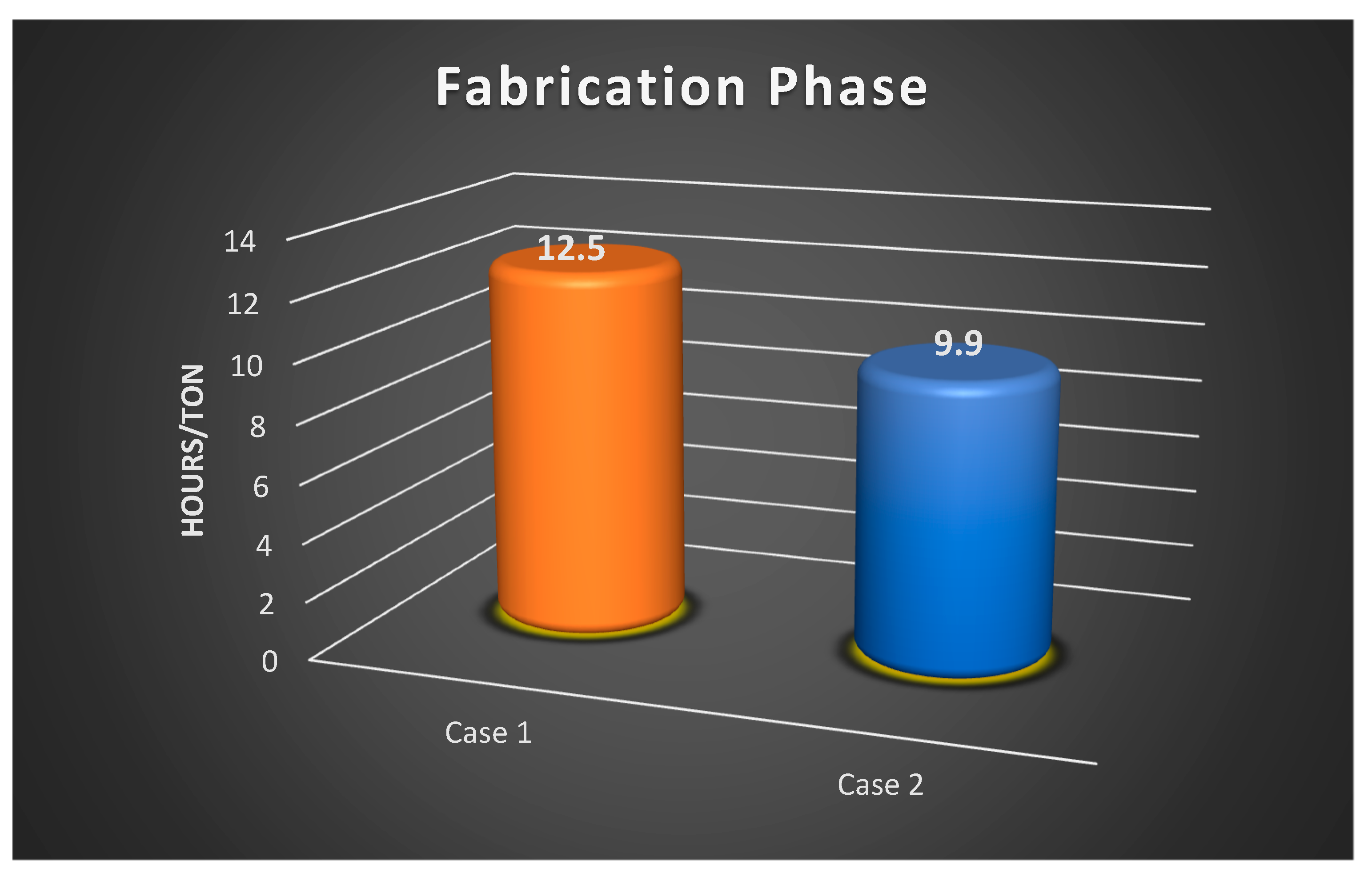
Figure 30 shows a bar graph summarizing the number of hours worked per ton in case studies 1 and 2.
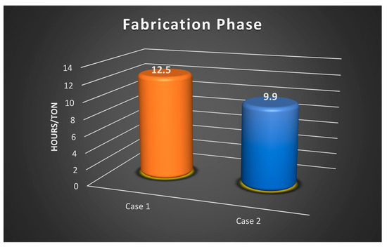
Figure 30.
Summary of fabrication hours/ton.
4. Discussion
This section presents the results and implications of the two case studies. The first case study utilized the traditional CAD-BIM methodology for the planning, design, and fabrication of a steel construction project. The second case study applied the BIM-DFE methodology, which has been validated by experts in the industry and scientific community, but has not yet been applied in a practical case study.
This discussion presents a comparison between the productivity indicators of both case studies, an analysis of the advantages and limitations of each methodology, and the potential impact of the BIM-DFE methodology on the steel construction industry.
4.1. Planning Phase
In case study 1, the traditional CAD-BIM methodology was used in the planning, design, and fabrication phases of a steel construction project, in which a total of 140 h was spent on planning: 60 h by the project manager/senior engineer and 80 h by a senior draftsman. The software tools used were AutoCAD and SAP2000. One disadvantage in this case was the use of two software tools that did not consider the transfer of nongraphical information between them, which slowed the planning process. Moreover, the presentation of 2D drawings to the client, who was not an expert in the construction industry, hindered their understanding of the project, which increased the period until the final design was approved.
In contrast, in the planning phase of case study 2, BIM tools following the BIM-DFE methodology were used together with the software tools Tekla and SAP2000. The use of BIM in this phase helped the client understand the final design, which was presented in 3D, thereby accelerating the planning process. The transfer of information between the software tools was bidirectional in the IFC format, allowing interactions regardless of the geographic location because the model was shared in the Trimble Connect cloud of Tekla. The senior engineer spent a total of 40 h in the planning phase. The hours spent by the draftsman were not considered because the same engineer/project manager conducted both the modeling and verification following the client’s approval. It should be noted that while the project sizes were significantly different, the typology was the same. As the project in case study 1 was significantly smaller than that in case study 2, the total hours spent in case study 2 was considerably lower, indicating improved performance.
Note that the objective of planning in both cases was to determine the quantity of steel (in tons) that could be processed to estimate the costs. Therefore, it can be concluded that the use of BIM technology following the BIM-DFE methodology in case study 2 improved the performance in the planning phase compared with that in case study 1, which used traditional CAD-BIM methodology. The reduced number of the hours spent on planning in case study 2 highlights the efficiency and effectiveness of applying BIM technology in the construction industry.
The traditional CAD-BIM method in the planning phase suffers from the drawback of limited integration between BIM and non-BIM software (e.g., AutoCAD and SAP2000). This could slow the process owing to the need to manually transfer nongraphical information between different software platforms. In addition, 2D drawings are not as effective as 3D models in communicating the design intent to the owner, which can lead to delays in the approval process and potentially increase the number of hours required to complete the planning phase. Another disadvantage is that the traditional CAD-BIM method could require more specialized personnel, such as a senior project manager and draftsman, compared with the BIM-DFE method, which requires fewer personnel with more diverse skill sets.
4.2. Design Phase
This study presents a comparison between two cases in the design phase of a construction project. In case study 1, the CAD-BIM utilized the traditional CAD method, in which the structural design was modeled in SAP engineering software and required 80 h from the senior engineer. After the analysis, a total of 100 h were spent on drawing: 60 h and 40 h by the senior and junior AutoCAD draftsman, respectively. The final design was disapproved by the client, and this required the engineer and senior AutoCAD draftsman to spend an additional 45 and 35 h, respectively, making necessary changes. This rejection was attributed to the client’s inability to understand the 2D plans, which prompted design changes. Finally, the senior engineer spent an additional 40 h calculating the connections, while the senior and junior draftsmen spent 50 and 40 h, respectively, representing the connections in 2D. An additional 60 h of drawing were required to complete the 2D deliverable in this phase.
In case study 2, the implementation of BIM-DFE utilized a BIM estimation derived from the previous planning phase. This facilitated the efficient exchange of information in the IFC file format for seamless integration with the SAP2000 calculation software. This process required only 20 h from the senior engineer. The need for draftsmen was eliminated as the model was seamlessly transferred bidirectionally to Tekla, and then to Trimble Connect for client comprehension. The manufacturing plant constraints were seamlessly integrated at this stage, which required an additional 12 h of the engineer/project manager’s time and 8 h of the senior manufacturing manager’s time. This early communication fostered an enriched BIM, enabling the analysis of connections that required an additional 10 h of the senior engineer’s time. To ensure the feasibility of these connections, an additional 15 h of the senior engineer’s time were allocated for verification purposes.
A comparison of the two cases showed that the use of BIM in the design phase has several advantages over traditional CAD methods. BIM facilitates the transfer of information for a more efficient design process with fewer errors. The early incorporation of manufacturing constraints helps identify potential issues, saves time, and reduces the likelihood of expensive changes in the future. In addition, the BIM model improves the visualization and facilitates the client’s understanding of the design, thereby reducing the risk of design changes due to misunderstanding. Furthermore, apart from the proven advantages highlighted in the case study, it is crucial to recognize that there are numerous other established and valuable benefits associated with BIM. These encompass improved collaboration, optimized project scheduling, and enhanced facility management. These additional advantages greatly contribute to the overall value and efficacy of BIM in construction projects.
In contrast, the traditional CAD method required more time and resources in the design phase, as seen in case study 1. Design changes were extensive and required significant additional time from the senior engineer and AutoCAD draftsmen. In addition, the 2D plan format made it difficult for the client to understand the design, leading to further design changes.
Overall, the use of BIM-DFE in the design phase has clear benefits over the traditional CAD method. It facilitates a more efficient and effective design process, and reduces the likelihood of expensive changes and misunderstandings.
4.3. Fabrication Phase
We conducted an analysis of the advantages and disadvantages of employing a manual process for production planning in case study 1. In contrast, case study 2 utilized BIM technology for planning and detailed modeling, specifically emphasizing the prioritization of elements for fabrication.
4.3.1. Advantages and Disadvantages in Case Study 1
In case study 1, the production planning process required 40 h to manually extract information from the 2D drawing files. This manual process is prone to errors and could cause delays in the production process. In addition, the nesting process required 20 h and preparation 2.5 h/t of steel.
The assembly and welding subprocess required 9.5 h/t. The painting subprocess required 0.5 h/t, which is relatively fast but may be insufficient for large-scale projects.
4.3.2. Advantages and Disadvantages in Case Study 2
In case study 2, the production planning process required only 1 h because information from the previous stage was already available in the BIM model. Obtaining the details of the parts to be fabricated was significantly faster because of the automated process. The cleaning routines for the drawings were preconfigured in Tekla, which reduced errors and lead times.
The information for nesting and production tracking was extracted in 2.5 h using tools such as Tekla and STRUMIS. Material preparation using a CNC plasma machine resulted in a productivity rate of 2.5 h/t, the same as that in case study 1. However, the assembly and welding subprocesses were significantly faster than those in case study 1, with a productivity rate of 7 h/t. This increase in productivity was attributed to the clarity of information presented in the 3D models, reducing the need for consultation with the fabrication manager and minimizing the need for the assembly and welding personnel to leave their workstations. The availability of information in the 3D model improved the organization of the workload. The painting subprocess had a productivity rate of 0.6 h/t, which is slightly better than that in case study 1. This was attributed to the size of Project 2 rather than the BIM-DFE.
Overall, the productivity indicator for case study 2 was 9.9 h/t. This is a reduction of 2.6 h/t and has a significantly positive impact on the manufacturing and construction durations of steel projects.
The use of BIM technology in the fabrication process offers several advantages over manual processing. Automated detailing, reduced errors, and increased clarity of information in the 3D model contribute to improved productivity. This improvement is particularly significant in critical subprocesses, such as assembly and welding. The use of BIM technology shortened lead times, reduced production costs, and increased customer satisfaction. However, the implementation of BIM-DFE requires investments in both software and personnel training.
BIM-DFE has proven to be a highly efficient methodology in the steel construction industry, as demonstrated by the case studies. BIM-DFE has the advantage of being specifically designed for steel construction by providing targeted solutions and optimizations for the unique challenges and requirements of this industry.
5. Conclusions
The analysis of the results of case studies 1 and 2 using the CAD-BIM and BIM-DFE methodologies, respectively, showed that BIM significantly improved the efficiency and productivity of the steel planning, design, and fabrication phases.
In case study 1, the manual extraction of information from 2D drawings extended the planning process, which led to longer processing times in the subsequent fabrication phase. In contrast, case study 2 exhibited notable improvements in planning and design, leading to a significant decrease in the duration of the fabrication phase, particularly the assembly and welding subprocesses. Case study 2 also demonstrated that the BIM-DFE methodology facilitated the automation of steel detailing by incorporating manufacturer constraints, resulting in a significant reduction in the time required for this process. BIM-DFE also reduced the need for human intervention, resulting in fewer errors and a more streamlined fabrication process.
The BIM-DFE methodology offers a more integrated approach, continuously enriching the model’s information from planning to fabrication, which ultimately results in a more efficient and effective process for all stakeholders. It can be concluded that the BIM-DFE methodology was not only validated by the literature and industry experts but also by its application to a real case in this study.
Among the limitations of this study is its focus on the planning, design, and fabrication phases of the project. Other phases, i.e., transportation and erection, were excluded owing to the timeline of the project.
Potential directions for future research related to this study include the following:
- Evaluation of the impact of BIM-DFE on the construction, transport, and installation processes;
- Exploration of the potential benefits of BIM-DFE in different types of construction projects, such as those using different materials or construction methods;
- Development of new tools and workflows to enhance the integration of BIM and DFE methodologies, such as the integration of optimization algorithms and machine learning techniques.
Author Contributions
Conceptualization, J.I.A., A.D. and S.Z.; Methodology, J.I.A., A.D. and S.Z.; Validation, J.I.A.; Formal analysis, J.I.A. and S.Z.; Investigation, J.I.A., A.D. and S.Z.; Resources, J.I.A.; Data curation, J.I.A., A.D. and S.Z.; Writing—original draft, J.I.A., A.D. and S.Z.; Writing—review & editing, J.I.A., A.D. and S.Z.; Visualization, J.I.A.; Project administration, J.I.A. All authors have read and agreed to the published version of the manuscript.
Funding
This research received no external funding.
Data Availability Statement
Not applicable.
Conflicts of Interest
The authors declare no conflict of interest.
References
- Avendaño, J.I.; Zlatanova, S.; Pérez, P.; Domingo, A.; Correa, C. Integration of BIM in steel building projects (BIM-DFE): A Delphi survey. Buildings 2022, 12, 1439. [Google Scholar] [CrossRef]
- Barbosa, F.; Woetzel, J.; Mischke, J.; Ribeirinho, M.J.; Sridhar, M.; Parsons, M.; Bertram, N.; Brown, S. Reinventing Construction: A Route to Higher Productivity; Mckinsey Global Insititute: New York, NY, USA, 2017. [Google Scholar]
- Stojanovska-Georgievska, L.; Sandeva, I.; Krleski, A.; Spasevska, H.; Ginovska, M.; Panchevski, I.; Ivanov, R.; Perez Arnal, I.P.; Cerovsek, T.; Funtik, T. BIM in the center of digital transformation of the construction sector—The status of BIM adoption in North Macedonia. Buildings 2022, 12, 218. [Google Scholar] [CrossRef]
- Bahamid, R.A.; Doh, S.I.; Khoiry, M.A.; Kassem, M.A.; Al-Sharafi, M.A. The Current Risk Management Practices and Knowledge in the Construction Industry. Buildings 2022, 12, 1016. [Google Scholar] [CrossRef]
- Basta, A.; Serror, M.H.; Marzouk, M. A BIM-based framework for quantitative assessment of steel structure deconstructability. Autom. Constr. 2020, 111, 103064. [Google Scholar] [CrossRef]
- London, K.; Pablo, Z.; Gu, N. Explanatory defect causation model linking digital innovation, human error and quality improvement in residential construction. Autom. Constr. 2021, 123, 103505. [Google Scholar] [CrossRef]
- Kim, K.; Kim, G.; Kim, K.; Lee, Y.; Kim, J. Real-time progress management system for steel structure construction. J. Asian Archit. Build. Eng. 2009, 8, 111–118. [Google Scholar] [CrossRef]
- Succar, B. Building information modelling framework: A research and delivery foundation for industry stakeholders. Autom. Constr. 2009, 18, 357–375. [Google Scholar] [CrossRef]
- Avendaño, J.I.; Zlatanova, S.; Domingo, A.; Pérez, P.; Correa, C. Utilization of BIM in steel building projects: A systematic literature review. Buildings 2022, 12, 713. [Google Scholar] [CrossRef]
- Kamunda, A.; Renukappa, S.; Suresh, S.; Jallow, H. BIM in the water industry: Addressing challenges to improve the project delivery process. Eng. Constr. Archit. Manag. 2020, 28, 510–529. [Google Scholar] [CrossRef]
- Niu, Y.; Lu, W.; Liu, D.; Chen, K.; Anumba, C.; Huang, G.G. An SCO-enabled logistics and supply chain–management system in construction. J. Constr. Eng. Manag. 2017, 143, 04016103. [Google Scholar] [CrossRef]
- Turk, Ž. Interoperability in construction—Mission impossible? Dev. Built Environ. 2020, 4, 100018. [Google Scholar] [CrossRef]
- Liu, Y.; Li, M.; Wong, B.C.L.; Chan, C.M.; Cheng, J.C.P.; Gan, V.J.L. BIM-BVBS integration with openBIM standards for automatic prefabrication of steel reinforcement. Autom. Constr. 2021, 125, 103654. [Google Scholar] [CrossRef]
- Sampaio, A.Z.; Sequeira, P.; Gomes, A.M.; Sanchez-Lite, A. BIM methodology in structural design: A practical case of collaboration, coordination, and integration. Buildings 2023, 13, 31. [Google Scholar] [CrossRef]
- Ding, Z.; Liu, S.; Liao, L.; Zhang, L. A digital construction framework integrating building information modeling and reverse engineering technologies for renovation projects. Autom. Constr. 2019, 102, 45–58. [Google Scholar] [CrossRef]
- Wang, W.C.; Weng, S.W.; Wang, S.H.; Chen, C.Y. Integrating building information models with construction process simulations for project scheduling support. Autom. Constr. 2014, 37, 68–80. [Google Scholar] [CrossRef]
- Ozcan Deniz, G. Emerging CAD and BIM trends in the AEC education: An analysis from students’ perspective. J. Inf. Technol. Constr. 2018, 23, 138–156. Available online: http://www.itcon.org/2018/7 (accessed on 1 March 2023).
- Rashidian, S.; Drogemuller, R.; Omrani, S. Building information modelling, integrated project delivery, and lean construction maturity attributes: A Delphi study. Buildings 2023, 13, 281. [Google Scholar] [CrossRef]
- Steel, J.; Drogemuller, R.; Toth, B. Model interoperability in building information modelling. Softw. Syst. Model. 2012, 11, 99–109. [Google Scholar] [CrossRef]
- Diakite, A.A.; Zlatanova, S. Automatic Geo-Referencing of BIM in GIS Environments Using Building Footprints. Comput. Environ. Urban Syst. 2020, 80, 101453. [Google Scholar] [CrossRef]
- Aleksandrov, M.; Diakité, A.; Yan, J.; Li, W.; Zlatanova, S. Systems architecture for management of bim, 3D GIS and sensors data. ISPRS Ann. Photogramm. Remote Sens. Spat. Inf. Sci. 2019, 4, 3–10. [Google Scholar] [CrossRef]
- Liu, L.; Li, B.; Zlatanova, S.; van Oosterom, P. Indoor Navigation Supported by the Industry Foundation Classes (IFC): A Survey. Autom. Constr. 2021, 121, 103436. [Google Scholar] [CrossRef]
- Alattas, A.; Kalogianni, E.; Alzahrani, T.; Zlatanova, S.; van Oosterom, P. Mapping Private, Common, and Exclusive Common Spaces in Buildings from BIM/IFC to LADM. A Case Study from Saudi Arabia. Land Use Policy 2021, 104, 105355. [Google Scholar] [CrossRef]
- Abou Diakité, A.; Zlatanova, S. Valid Space Description in BIM for 3D Indoor Navigation. Int. J. 3-D Inf. Model. 2016, 5, 1–17. [Google Scholar] [CrossRef]
- Isikdag, U.; Zlatanova, S.; Underwood, J. A BIM-Oriented Model for Supporting Indoor Navigation Requirements. Comput. Environ. Urban Syst. 2013, 41, 112–123. [Google Scholar] [CrossRef]
- Azhar, S. Building Information Modeling (BIM): Trends, benefits, risks, and challenges for the AEC Industry. J. Leadersh. Manag. Eng. 2011, 11, 241–252. [Google Scholar] [CrossRef]
- Wang, Y.G.; He, X.J.; He, J.; Fan, C. Virtual trial assembly of steel structure based on BIM platform. Autom. Constr. 2022, 141, 104395. [Google Scholar] [CrossRef]
- Alizadehsalehi, S.; Hadavi, A.; Huang, J.C. From BIM to extended reality in AEC industry. Autom. Constr. 2020, 116, 103254. [Google Scholar] [CrossRef]
- Costin, A.; Hu, H.; Medlock, R. Building information modeling for bridges and structures: Outcomes and lessons learned from the steel bridge industry. Transp. Res. Rec. 2021, 2675, 576–586. [Google Scholar] [CrossRef]
- Soh, M.F.; Bigras, D.; Barbeau, D.; Doré, S.; Forgues, D. Bim machine learning and design rules to improve the assembly time in steel construction projects. Sustainability 2022, 14, 288. [Google Scholar] [CrossRef]
- Disney, O.; Roupé, M.; Johansson, M.; Domenico Leto, A. Embracing BIM in its totality: A Total BIM case study. Smart Sustain. Built Environ 2022. ahead-of-print. [Google Scholar] [CrossRef]
- Jeon, K.; Lee, G.; Kang, S.; Roh, H.; Jung, J.; Lee, K.; Baldwin, M. A relational framework for smart information delivery manual (IDM) specifications. Adv. Eng. Inform. 2021, 49, 101319. [Google Scholar] [CrossRef]
- Tang, S.; Shelden, D.R.; Eastman, C.M.; Pishdad-Bozorgi, P.; Gao, X. BIM assisted Building Automation System information exchange using BACnet and IFC. Autom. Constr. 2020, 110, 103049. [Google Scholar] [CrossRef]
- Arayici, Y.; Fernando, T.; Munoz, V.; Bassanino, M. Interoperability specification development for integrated BIM use in performance based design. Autom. Constr. 2018, 85, 167–181. [Google Scholar] [CrossRef]
- Sacks, R.; Kedar, A.; Borrmann, A.; Ma, L.; Brilakis, I.; Hüthwohl, P.; Daum, S.; Kattel, U.; Yosef, R.; Liebich, T.; et al. SeeBridge as next generation bridge inspection: Overview, Information Delivery Manual and Model View Definition. Autom. Constr. 2018, 90, 134–145. [Google Scholar] [CrossRef]
- Qiu, Q.; Zhou, X.; Zhao, J.; Yang, Y.; Tian, S.; Wang, J.; Liu, J.; Liu, H. From sketch BIM to design BIM: An element identification approach using Industry Foundation Classes and object recognition. Build. Environ. 2021, 188, 107423. [Google Scholar] [CrossRef]
- Ramaji, I.J.; Messner, J.I.; Mostavi, E. IFC-based BIM-to-BEM model transformation. J. Comput. Civ. Eng. 2020, 34, 04020005. [Google Scholar] [CrossRef]
- Wu, J.; Asce, S.M.; Zhang, J.; Asce, A.M. New automated BIM object classification method to support BIM interoperability. J. Comput. Civ. Eng. 2019, 33, 04019033. [Google Scholar] [CrossRef]
- Shan, Y.; Goodrum, P.; Haas, C.; Caldas, C. Assessing productivity improvement of quick connection systems in the steel construction industry using building information modeling (BIM). In Proceedings of the Construction Research Congress 2012: Construction Challenges in a Flat World, West Lafayette, IN, USA, 21–23 May 2012; pp. 1135–1144. [Google Scholar]
- Bartenbach, J.; Schindler, S.; Schulze, F.; Kulzer, W. Stahlbau unter Nutzung von BIM in einem heterogenen Softwareumfeld. Stahlbau 2019, 88, 786–795. [Google Scholar] [CrossRef]
- Tavares, P.; Costa, C.M.; Rocha, L.; Malaca, P.; Costa, P.; Moreira, A.P.; Sousa, A.; Veiga, G. Collaborative welding system using BIM for robotic reprogramming and spatial augmented reality. Autom. Constr. 2019, 106, 102825. [Google Scholar] [CrossRef]
- Ramaji, I.J.; Memari, A.M.; Messner, J.I. Product-oriented information delivery framework for multistory modular building projects. J. Comput. Civ. Eng. 2017, 31, 04017001. [Google Scholar] [CrossRef]
- Son, S.; Lee, G.; Jung, J.; Kim, J.; Jeon, K. Automated generation of a model view definition from an information delivery manual using idmXSD and buildingSMART data dictionary. Adv. Eng. Inform. 2022, 54, 101731. [Google Scholar] [CrossRef]
- Vaughan, J.L.; Leming, M.L.; Liu, M.; Jaselskis, E. Cost-benefit analysis of construction information management system implementation: Case study. J. Constr. Eng. Manag. 2013, 139, 445–455. [Google Scholar] [CrossRef]
- Pan, W.; Zhang, Z. Evaluating modular healthcare facilities for COVID-19 emergency response—A case of Hong Kong. Buildings 2022, 12, 1430. [Google Scholar] [CrossRef]
- Gerbino, S.; Cieri, L.; Rainieri, C.; Fabbrocino, G. On bim interoperability via the ifc standard: An assessment from the structural engineering and design viewpoint. Appl. Sci. 2021, 11, 11430. [Google Scholar] [CrossRef]
- Sibenik, G.; Kovacic, I. Assessment of model-based data exchange between architectural design and structural analysis. J. Build. Eng. 2020, 32, 101589. [Google Scholar] [CrossRef]
- Lucko, G.; Asce, A.M.; Rojas, E.M. Research validation: Challenges and opportunities in the construction domain. J. Constr. Eng. Manag. 2010, 136, 127–135. [Google Scholar] [CrossRef]
- Leon, H.; Osman, H.; Georgy, M.; Elsaid, M. System dynamics approach for forecasting performance of construction projects. J. Manag. Eng. 2018, 34, 04017049. [Google Scholar] [CrossRef]


Disclaimer/Publisher’s Note: The statements, opinions and data contained in all publications are solely those of the individual author(s) and contributor(s) and not of MDPI and/or the editor(s). MDPI and/or the editor(s) disclaim responsibility for any injury to people or property resulting from any ideas, methods, instructions or products referred to in the content. |
© 2023 by the authors. Licensee MDPI, Basel, Switzerland. This article is an open access article distributed under the terms and conditions of the Creative Commons Attribution (CC BY) license (https://creativecommons.org/licenses/by/4.0/).