Article

Shear Behavior and Analytical Method of Vertically Corrugated Steel Plate Shear Walls with Inelastic Buckling of Infilled Plates

1
College of Transportation Engineering, Tongji University, Shanghai 201804, China
2
College of Civil Engineering, Tongji University, Shanghai 200092, China
3
National Maglev Transportation Engineering R&D Center, Tongji University, Shanghai 201804, China
*
Author to whom correspondence should be addressed.
Buildings 2023, 13(9), 2184; https://doi.org/10.3390/buildings13092184
Submission received: 27 July 2023 / Revised: 14 August 2023 / Accepted: 21 August 2023 / Published: 28 August 2023
(This article belongs to the Section Building Structures)

Abstract

:
This paper presents numerical investigations of the shear performance of vertically corrugated steel plate shear walls (CvSPSWs) with inelastic buckling of infilled plates under lateral loads. A numerical model was developed and verified by an experiment. Subsequently, a series of parametric analyses were conducted to investigate the effects of the concerned parameters on the shear performance of CvSPSWs, such as the connection type, height–thickness ratio, aspect ratio, horizontal subpanel width, and surrounding beam stiffness, in which the loading mechanism, buckling behavior, and failure modes of the corrugated steel plate (CSP) in the CvSPSW were discussed. The results show that CvSPSWs exhibit large initial stiffness, in-plane and out-of-plane strength, and good displacement ductility. Further, a formula for predicting the buckling strength of the CSP in the CvSPSW is proposed, and the effect of the section stiffness of the inclined subpanel on buckling strength and the development of the tension field of the CSP was investigated. In addition, simplified analytical models for CvSPSWs were examined to simplify the elastoplastic analysis of CvSPSWs. The results show that the plate-frame interaction model and the modified strip model can reproduce the shear performance of CvSPSWs with good accuracy.

1. Introduction

Corrugated steel plates (CSPs) are widely used in container architecture structures, corrugated webs of beams in buildings, and bridge structures due to the advantages of the corrugation of CSPs [1,2,3,4]. In recent years, corrugated steel plate shear walls with CSPs horizontally placed (ChSPSWs) have attracted great attention from domestic and foreign scholars. The mechanical properties of CSPs are orthotropic along directions parallel and perpendicular to the corrugation of the CSPs, as shown in Figure 1 [5,6]. There are big differences in shear performance between CvSPSWs and ChSPSWs. The CvSPSWs are good choices for shear walls with openings. The ultimate strength of the corrugated steel plates (CSPs) in the CvSPSWs with interactive buckling decreases much less than that of the flat steel plate shear walls or corrugated steel plate shear walls with corrugation laid horizontally (ChSPSWs) [7]. In addition, the CvSPSWs with the medium-thick infilled plates are suitable for shear wall structures with large aspect ratios. Due to the constraints from vertically inclined subpanels connected to beams, the tension fields of CSPs in the CvSPSWs with large aspect ratios develop more fully than those of the CSPs in the ChSPSWs with the same aspect ratios, and the strength of the CvSPSWs with interactive buckling of CSPs with large aspect ratios is much larger than that of CSPs in the ChSPSWs with the same aspect ratios. When the CvSPSWs have medium-thick infilled plates, of which buckling modes are interactive buckling of CSPs, the loading mechanism and analytical method of the CvSPSWs with interactive buckling of CSPs differ from those of ChSPSWs, corrugated webs, and container architecture structures with thin CSPs due to the constraints from inclined subpanels connected to neighboring beams. However, studies on the shear performance of CvSPSWs with interactive buckling of CSPs are few. Therefore, an investigation of the shear performance of the CvSPSW with interactive buckling of the CSP is necessary.
Extensive research has been carried out on the static and seismic behavior of ChSPSWs. The post-buckling strength and hysteretic performance of ChSPSWs with thin CSPs were investigated, in which CSPs buckled at early elastic loading [8,9,10,11]. In order to improve the buckling strength of the infilled plates, studies on the structural performance of ChSPSWs with mid-thick plates were carried out [8,9]. The results showed that ChSPSWs showed greater strength, stiffness, and stable energy dissipation. The geometry parameters of the CSPs played an important role in the buckling strength, ultimate strength, and failure modes of the CSPs [2,10,11,12,13,14], and ChSPSWs could avoid buckling of the CSPs by proper design of the parameters [15]. In addition, the stiffeners to avoid the buckling of the CSP were also investigated [16]. The shear and seismic performance of the ChSPSWs with openings of CSPs were studied, and the ultimate loads of the shear walls with openings were proposed based on the numerical results [17]. In addition, the simplified analytical models for the ChSPSWs were studied. The results showed that the PFI (plate-frame interaction) model and strip model could simulate the initial stiffness and ultimate load of ChSPSWs [8,18].
The structural performance of a CvSPSW with a thin CSP has also been a study subject for researchers in recent years. The effects of the parameters of CSPs on the shear performance of CvSPSWs were discussed [19,20,21,22,23]. The height–thickness ratio and surrounding frame stiffness played an important role in the seismic performance of CvSPSWs with thin CSPs. In addition, parametric analysis for CvSPSWs with both sides connected to surrounding beams was conducted [7]. The results showed that the initial stiffness and lateral bearing capacity of CSPs in CvSPSWs with two-side connections increased with the increase in CSP width, and the layout of the structures could be adjusted freely. The CvSPSWs were good choices for shear walls with openings.
Further, a plate torsion test and a correctly formulated analytical description were used to determine the contribution of transverse shear to the corrugated cardboard plates. The results showed that the transverse shear effect could not be omitted in some cases [24]. The compressive strength of flap boxes made of corrugated cardboard was estimated based on the McKee formula [25]. The various homogenization techniques [26,27,28,29,30] were adopted to develop the building substitute models for corrugated cardboard [31,32]. In addition, continuum mechanics were adopted to investigate the mechanical response of structures, buckling, free vibrations, forced vibrations of membranes, and forest-like composite layers, plates, and shells [33,34,35,36,37,38,39,40,41,42,43,44]. Continuum mechanics had potential advantages for seismic performance analyses of structures.
There are a large number of studies on the static and seismic behavior of ChSPSWs and some preliminary studies on the static and seismic behavior of CvSPSWs. However, the loading mechanism of the CvSPSW with a medium-thick plate differs from that of the ChSPSW with a medium-thick plate. This is because the inclined subpanels in the CvSPSWs with medium-thick CSPs connected to beams provide extra constraints for the tension field of the CSPs. There are few previous studies on the loading mechanism of the CvSPSW with a medium-thick plate. The loading mechanism and analytical method of the CvSPSWs with medium-thick plates under lateral loads are not clearly described, of which buckling modes are counted as interactive buckling of the CSPs. This paper focused on the shear performance of CvSPSWs with interactive buckling of CSPs under lateral loads. The loading mechanism and analytical method of the CvSPSWs with interactive buckling of CSPs were investigated. Moreover, the effects of the concerned parameters on the shear behavior of CvSPSWs were evaluated. The buckling strength formula for the CSP in the CvSPSW with interactive buckling of the CSP was investigated. In addition, the section stiffness of the inclined subpanel’s effect on the buckling strength of the CSP was discussed. Furthermore, simplified analytical models for CvSPSWs were examined to simplify the elastoplastic analyses for the CvSPSWs with interactive buckling of CSPs.

2. Computational Study

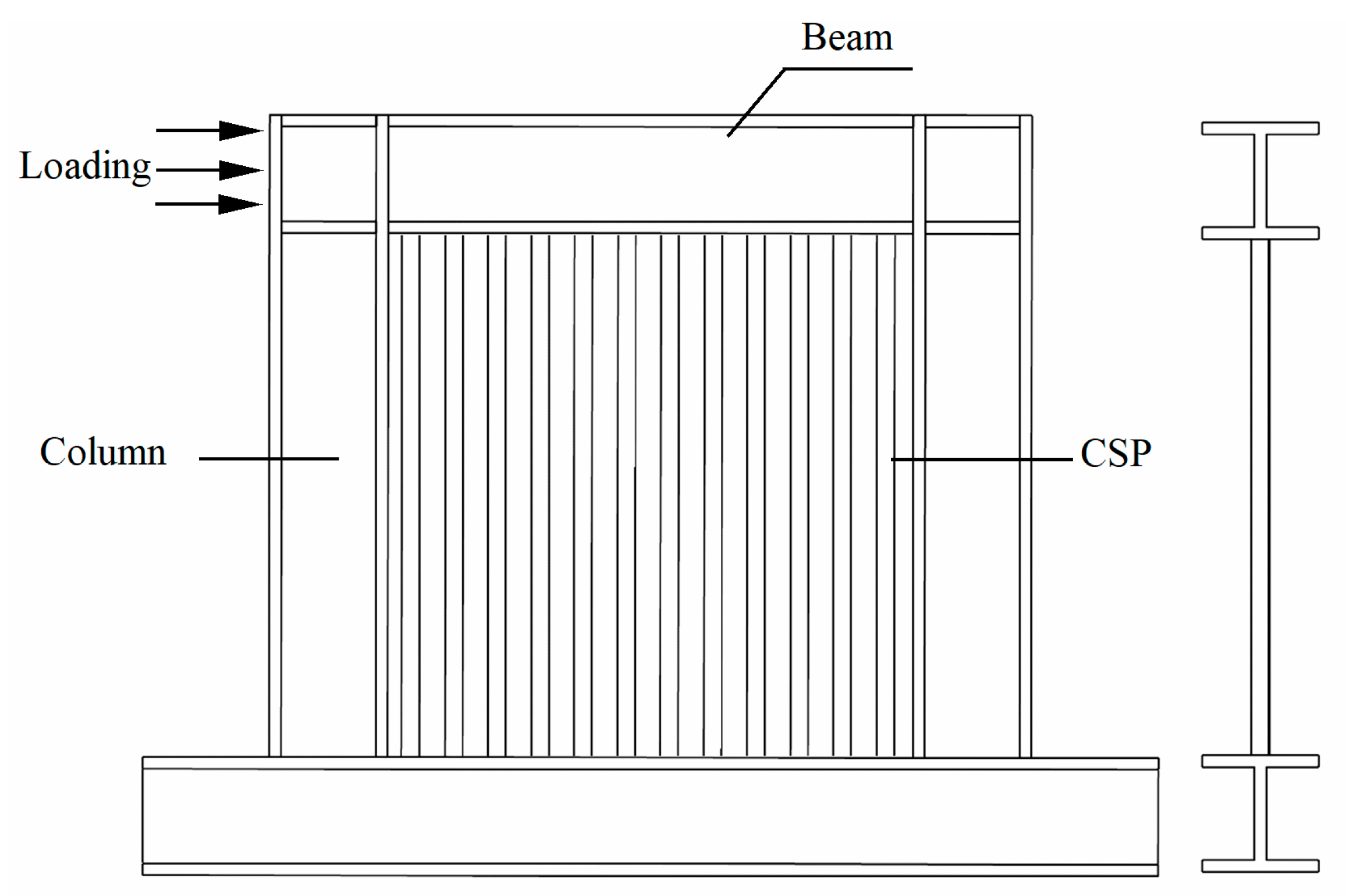
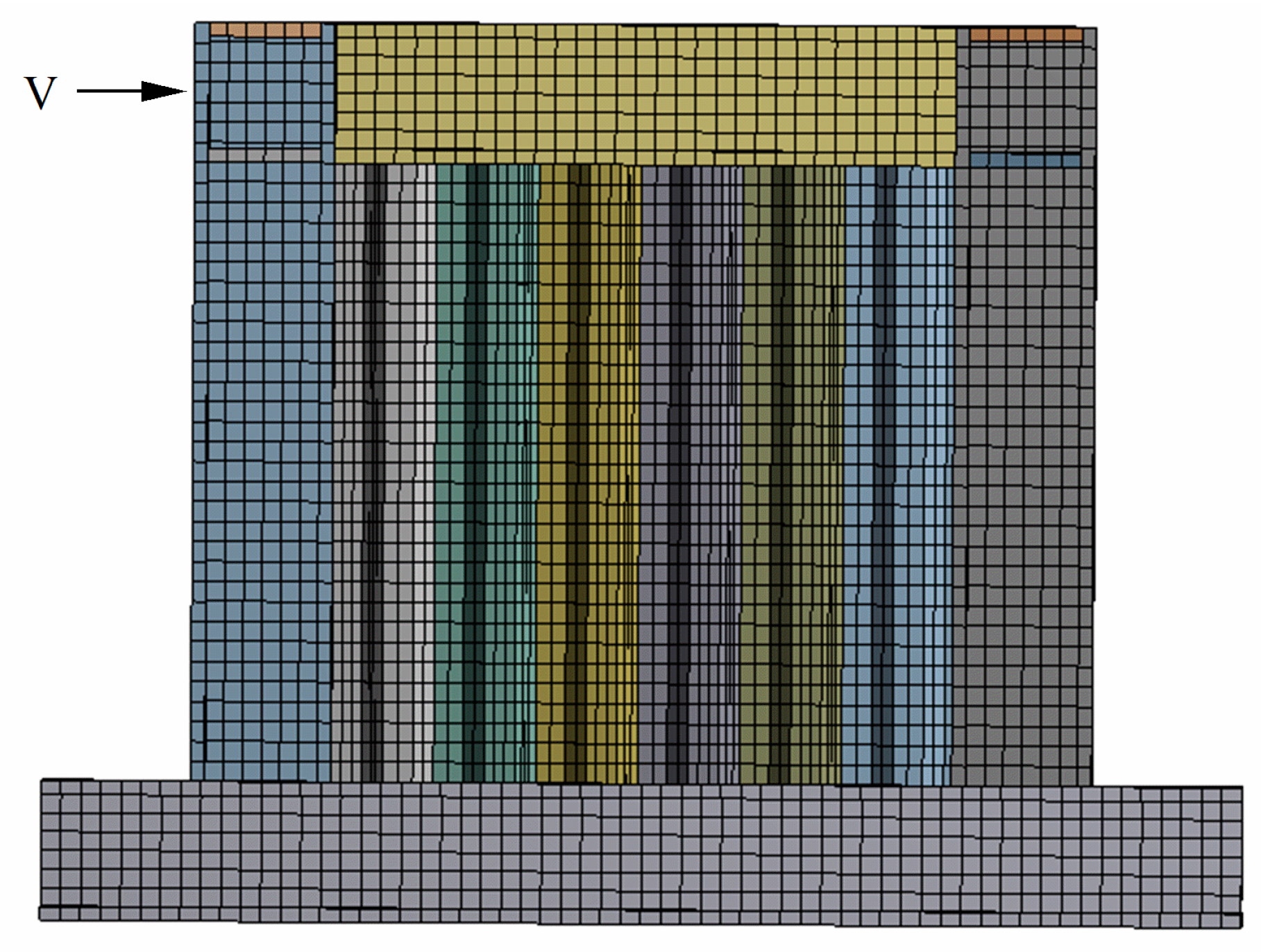
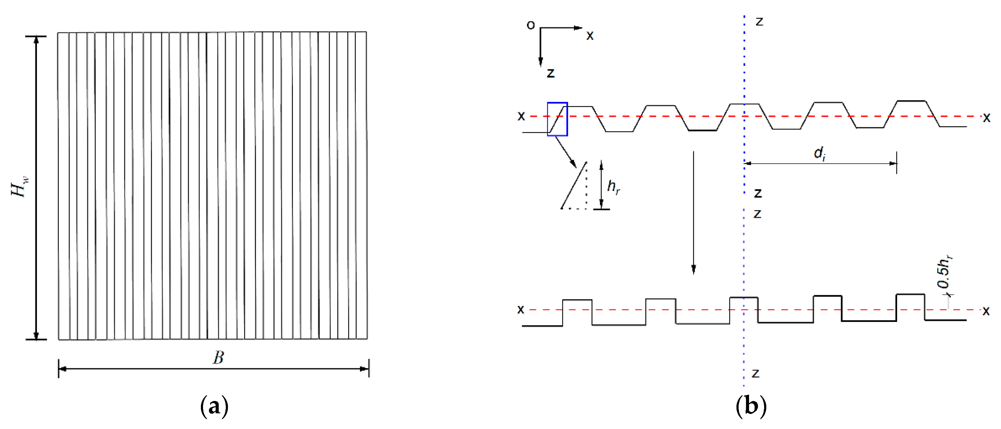
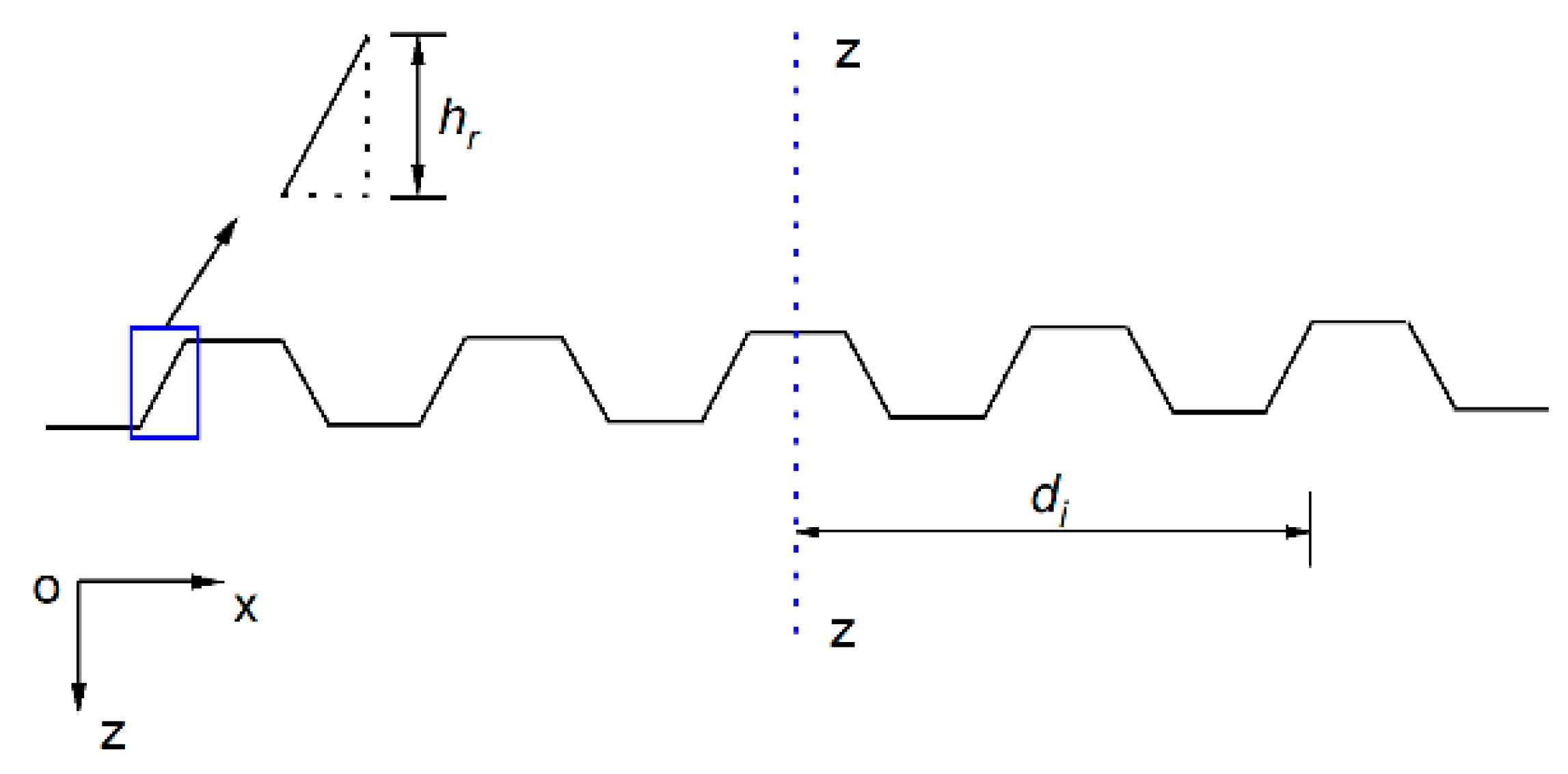
2.1. Finite Element Model

Finite element (FE) analysis is one of the micro-analysis methods that is an effective tool to study the overall performance and macro-mechanical properties of structures. In this paper, the shear performance of CvSPSWs under lateral loads has been investigated using the general FEM software ANSYS v.19.0.
A single-bay, one-story CvSPSW was designed. The diagram of the designed model is shown in Figure 2. In the model, connections between columns and beams were rigid, and vertical CSPs were welded to surrounding columns and beams. In addition, the specimen was subjected to a lateral load, such as an earthquake or wind load, which was applied on the column end close to the connection between the column and beam. The materials of the frame and CSP were Q345- and Q235-grade steel, respectively.
Based on the designed specimen, a FE model was developed to simulate the shear performance of the CvSPSW. The shell 181 element with six degrees of freedom at each node was adopted to simulate the performance of columns, beams, and CSPs of the CvSPSW. The connections between the CSPs and adjacent beams and the connections between the CSPs and adjacent columns were rigid. The CSPs shared common nodes with the adjacent beams and columns in these connections. Therefore, these connections between the CSPs and surrounding frames were destroyed after the failures of the CSPs, beams, and columns. The ideal elastoplastic model was used to simulate the stress–strain relationship of the steel material. The von Mises yield criterion and the associated flow rule were adopted in the model. The boundary conditions and lateral loads concurred with those of the designed specimen. In addition, the out-of-plane displacement of the surrounding frame was restrained to avoid eccentric loading on the FE model. The initial imperfection of the CSPs was applied to the FE model by multiplying one thousandth of a CSP height by the out-of-plane displacement of the CSP obtained from the eigen buckling of the FE model. The mesh sensitivity analyses were conducted as shown in Figure 3. When the mesh size of the shell element was less than 30 mm × 30 mm, the ultimate loads of the FE models tended to be stable. Figure 4 shows the meshed FE model.

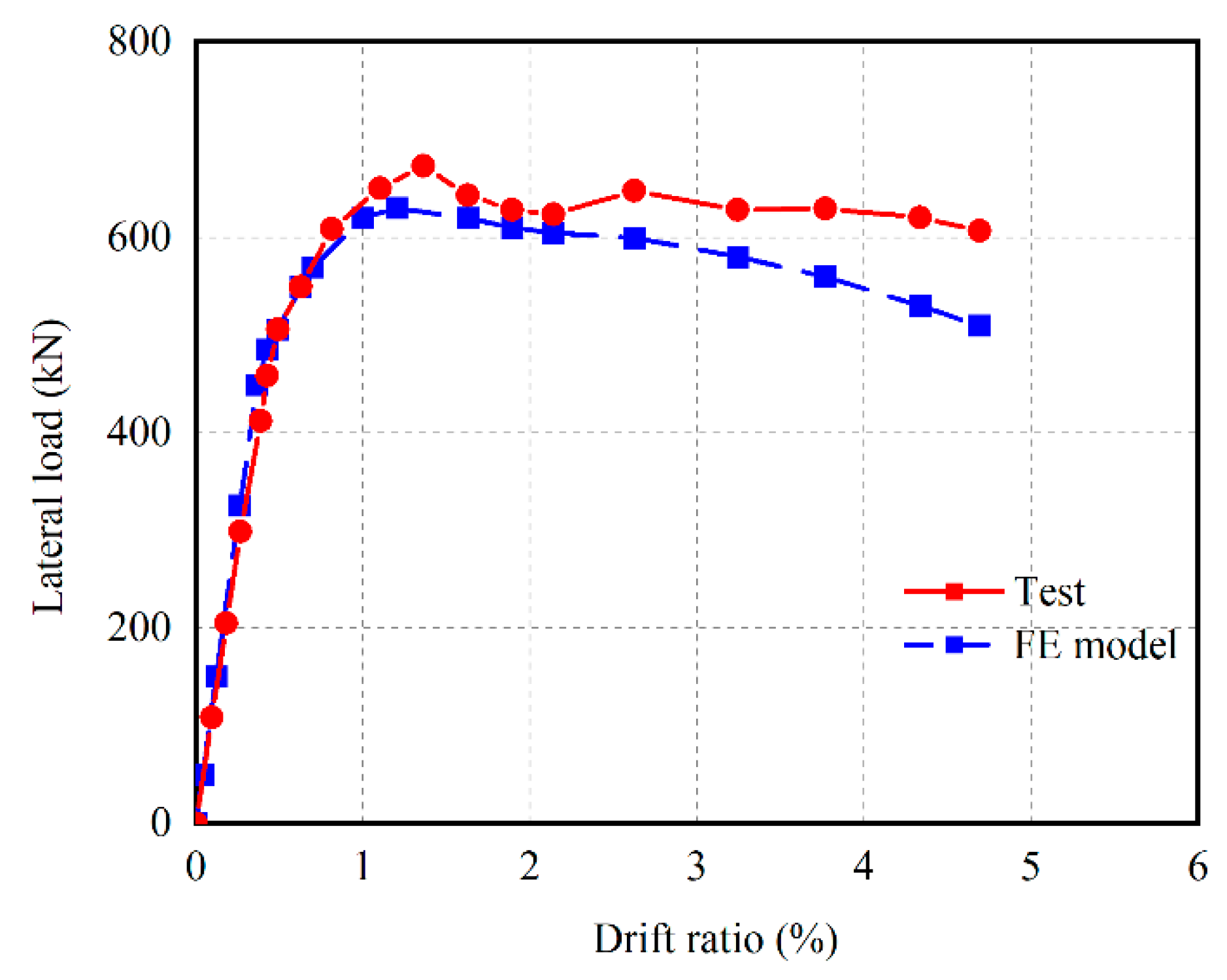
2.2. Verification Study

The developed FE model for the CSPSW was verified by a laboratory test [45]. In accordance with the test specimen, a numerical model for the test specimen was developed. The material properties, boundary conditions, and loading protocols were in agreement with those of the test specimen. A comparison of the load–displacement curves between the FE model and test specimen is shown in Figure 5.
From Figure 5, the ultimate strength ratio of the FE model to the test specimen is 0.94, and the displacement corresponding to the ultimate strength ratio of the former to the latter is 0.88. It is indicated that the adopted FE model can simulate the load–displacement curve of the CvSPSW with reasonable accuracy.

3. Parametric Analyses and Discussions

Based on the verified FE model, extensive parametric analyses were carried out to study the effects of the concerned parameters on the shear performance of CvSPSWs, including the connection type, height–thickness ratio, aspect ratio, horizontal subpanel width, and surrounding column stiffness. The detailed parameters of these CvSPSWs are shown in Table 1.

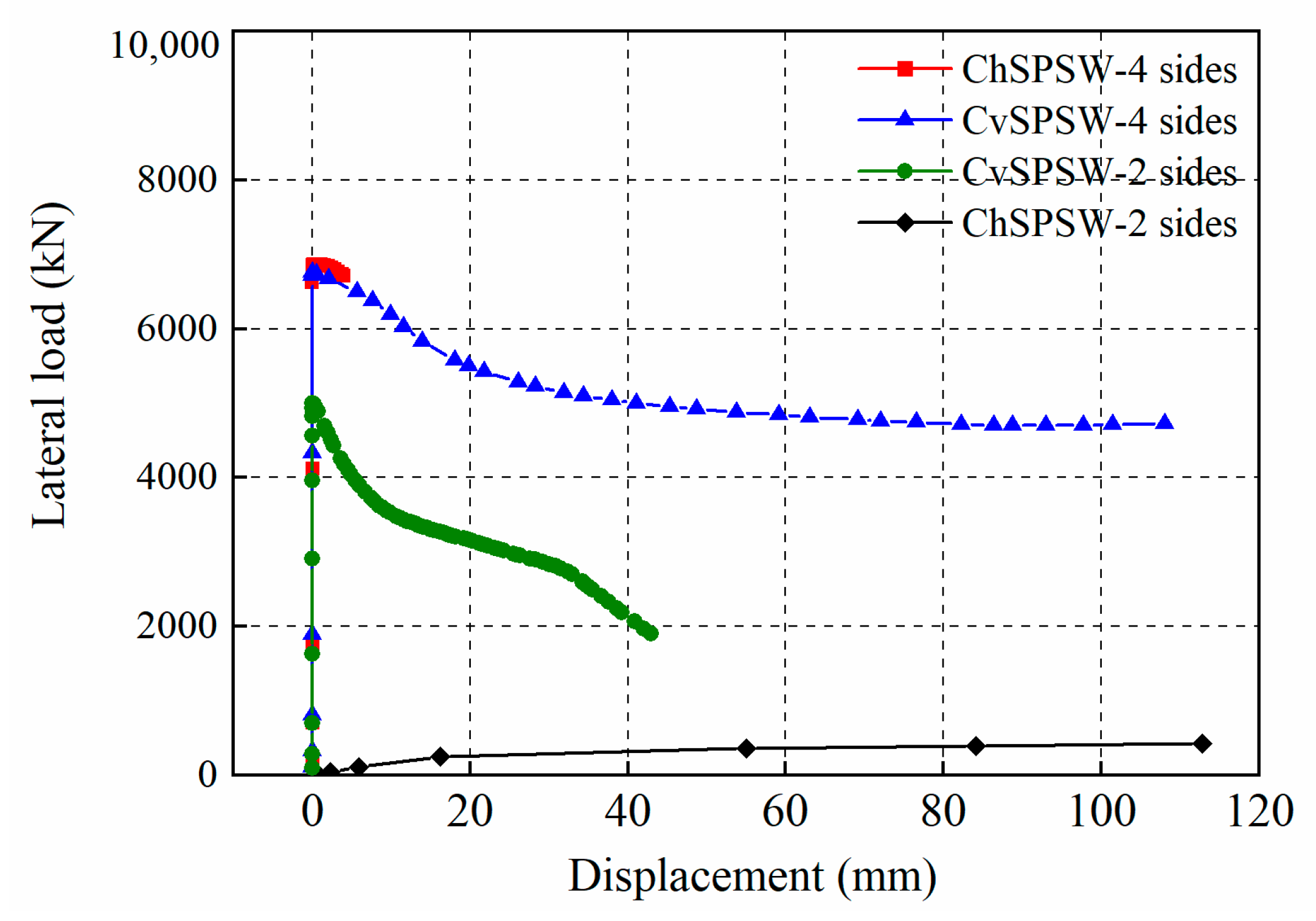
3.1. Connection Type Effect

In order to investigate the connection type effect on the behavior of CvSPSWs under lateral loads, four CvSPSW and ChSPSW specimens ( λ = 300 ) with different connection types, two-side and four-side connections, were developed. In these models, the surrounding frames, columns, and CSPs had uniform sizes. The comparisons of the bucking strength, load–displacement curves, and failure modes in the CvSPSWs and ChSPSWs were conducted.
The load–displacement curves and load vs. out-of-plane displacement curves of these models are shown in Figure 6 and Figure 7. From the figures, the shear performance of the shear walls with different connection types shows great differences. In these shear walls, the ultimate strength of the ChSPSW with four-side connections is the highest; the ChSPSW with two-side connections has the least ultimate strength; and the CvSPSW with four-side and two-side connections has intermediate ultimate strength. The ultimate load of the CvSPSW with four-side connections is 92% of that of the ChSPSW with four-side connections. In addition, after the peak load, the rate of strength decline of the CvSPSW with two-side connections is faster than that of the CvSPSW with four-side connections. It is noted that the strength of the ChSPSW with two side connections shows a jump decrease compared to that of the ChSPSW with four-side connections, which is just about 16% of the strength of the ChSPSW with four-side connections. It is indicated that the ChSPSW cannot be directly used in shear walls with openings, which should be strengthened in future designs. However, the ultimate strength of the CvSPSW with two side connections is 73% greater than that of the CvSPSW with four-side connections. The CvSPSW with two-side connections has a large strength and initial stiffness and is an optional lateral resisting system for shear walls with openings.
In addition, the out-of-plane deformation of the ChSPSW and CvSPSW with height–thickness ratio λ = 300 is shown in Figure 8. There are five half-waves in the CvSPSW with four side connections, and there are four half-waves in the ChSPSW with four side connections. Furthermore, the tension field in the CvSPSW with four-side connections develops more fully than that of the ChSPSW with four-side connections due to the vertically inclined subpanels.

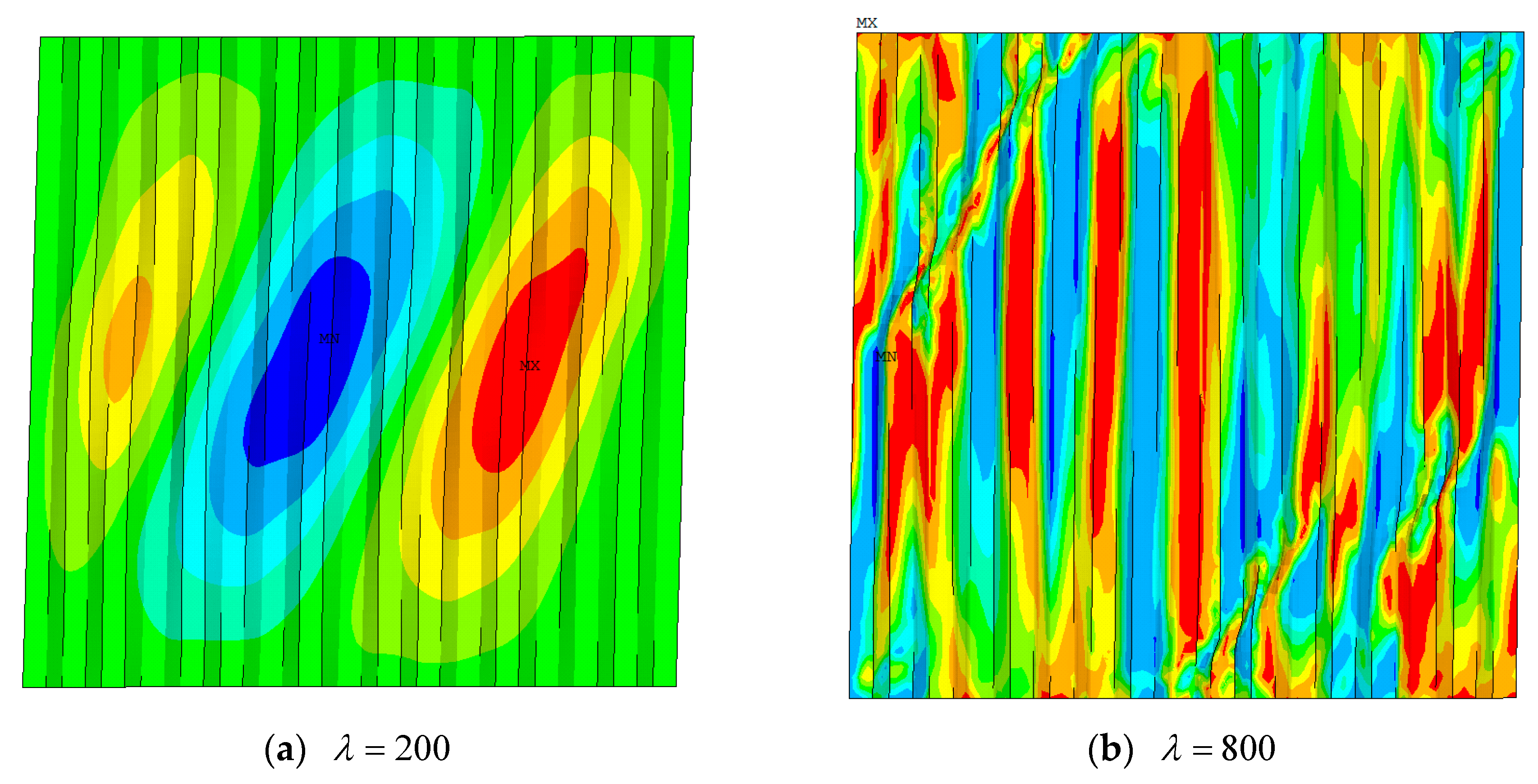
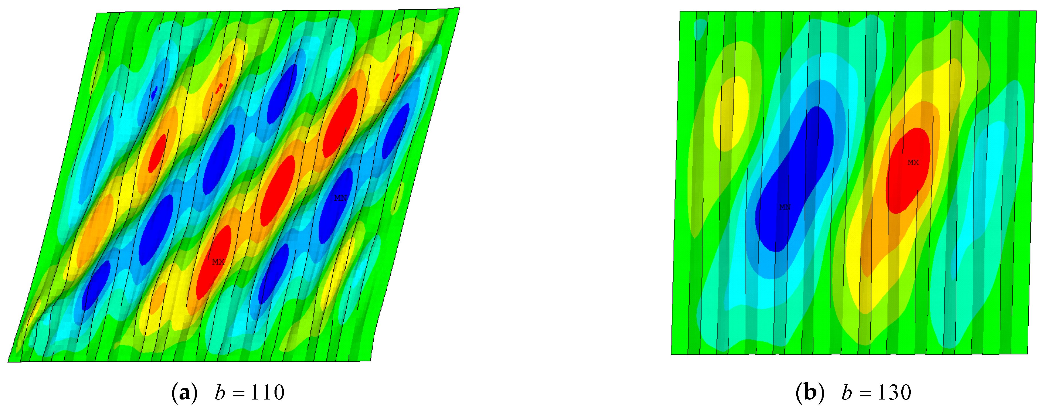
3.2. Height–Thickness Ratio Effect

Eight specimens with height–thickness ratios of 100, 200, 300, 400, 500, 600, 800, and 1500 were developed to study the height–thickness ratio’s effect on the shear performance of CvSPSWs, and the corresponding thicknesses of CSPs were 31.0, 15.5, 10.3, 7.8, 6.2, 5.2, 3.9, and 2.1 mm, respectively. In these models, the width of CSPs remained unchanged. The parameters of the shear walls are shown in Table 1. The load–displacement curves of these CvSPSWs are shown in Figure 9. The load vs. out-of-plane displacement curves with different height–thickness ratios are shown in Figure 10.
From Figure 9, with the increase in the height–thickness ratio, the initial stiffness and ultimate strength of the CSP increase. After the peak load, the larger the height–thickness ratio is, the faster the load decreases. From Figure 10, the buckling strength of the CSP shows a positive relationship with the height–thickness ratio. However, the buckling modes, ways of resisting lateral load, and failure modes of CvSPSWs with various height–thickness ratios show some differences. When the height–thickness ratio is less than 200, the buckling modes of CSPSWs are plastic global bucking of CSPs, and the CvSPSWs mainly resist lateral loads by pure shear, and the corresponding failure modes are tension field failure, shown in Figure 11a. However, when the height–thickness ratio falls in the range of 300 to 800, the buckling modes of CSPs are interactive buckling. After interactive buckling of CSPs, the shear walls continue to bear greater loads due to the tension field, as shown in Figure 11b. When the height–thickness ratio reaches 1500, elastic buckling of the CSP occurs in the early loading stage. The method of resisting lateral loads relies on the tension field of the CSP, and the shear wall continues to bear a greater load due to the tension field. From Figure 11, the tension field in the CvSPSW with a height–thickness ratio λ = 200 develops more fully than that of the CvSPSW with λ = 800 .

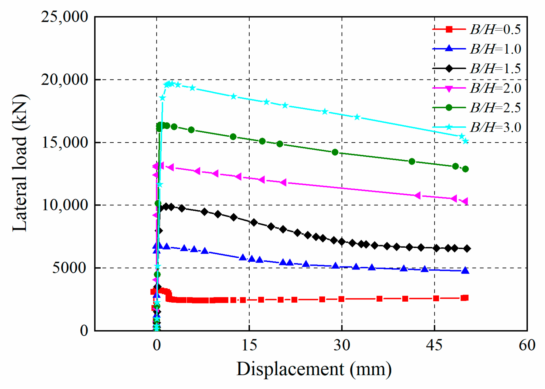
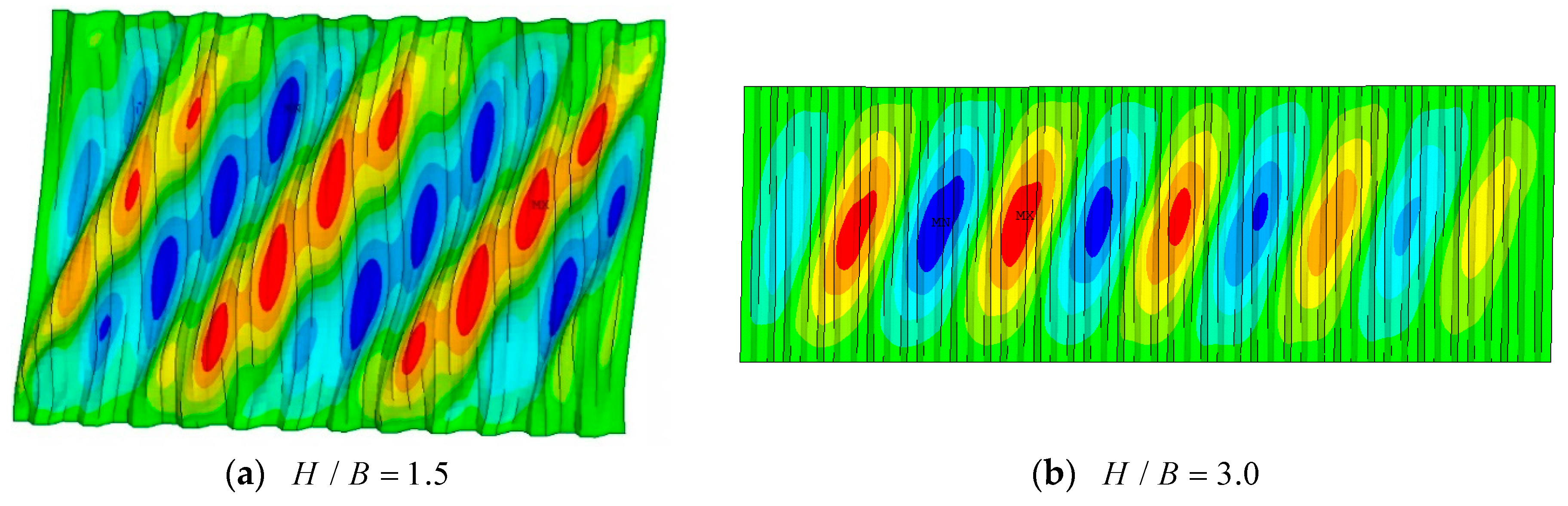
3.3. Aspect Ratio Effect

The aspect ratio of the infilled plate plays an important part in the shear performance of the shear wall. Six specimens with various aspect ratios of 0.5, 1, 1.5, 2.0, 2.5, and 3 were established to investigate the parameter effect on the shear behavior of the CvSPSW, in which the CSP heights were maintained unchanged. In addition, in accordance with the six CvSPSW specimens, six ChSPSWs with the same aspect ratios were also developed. The load–displacement curves of these CvSPSWs are shown in Figure 12. The load vs. out-of-plane displacement curves with different aspect ratios are shown in Figure 13.
From Figure 12, the buckling strength, ultimate strength, and initial stiffness of the CSPs increase with the increase in the aspect ratio. The displacement ductility of the shear wall shows a negative relationship with the aspect ratio. However, the buckling stress of the CSP presents a different trend, as shown in Figure 13. The buckling stress of the CSP vs. the aspect ratio curves of the CvSPSWs and ChSPSWs are shown in Figure 14. The buckling stresses of the CSPs are 204.7, 213.0, 203.0, 170.8, 146.0, and 130.2 MPa, respectively, when the aspect ratios of the CSPs in the ChSPSWs are 0.5, 1, 1.5, 2, 2.5, and 3.0. From the figure, when the aspect ratio exceeds 2.0, the buckling stresses of the CSPs in the ChSPSWs are smaller than the requirements of the strength design value in the Code for Seismic Design of Building (GB50011-2010) [46]. Therefore, the aspect ratio is usually suggested to be less than 2.0 in the ChSPSWs without stiffeners to meet the strength and stiffness requirements. However, the buckling stresses of the CSPs in the CvSPSWs are 193.9, 210.0, 208.7, 209.1, 208.1, and 208.3 MPa, respectively, when the aspect ratios of the CSPs are 0.5, 1, 1.5, 2, 2.5, and 3.0. This is a big difference between the CvSPSW and ChSPSW. This is because, with the exception of constraints from surrounding columns, the tension field of CSPs relies on the constraints from inclined panels in ChSPSWs, while the tension field of the horizontal subpanels in CvSPSWs also relies on the constraints from vertical inclined subpanels connected to the surrounding beams. When the CvSPSWs and ChSPSWs have large aspect ratios, the constraints from columns become weak in ChSPSWs, while the constraints from inclined subpanels rely on the spacings of inclined subpanels, which remain unchanged along the lateral loads in CvSPSWs. Therefore, the constraints of the horizontal subpanels and the buckling strength of CSPs in CvSPSWs are insensitive to the aspect ratios of the CSPs. In the CvSPSWs and ChSPSWs, the more obvious the phenomenon is, the larger the aspect ratio is. It is this characteristic that allows the flexible layout of openings in CvSPSWs without taking the strength and stiffness reductions for the openings of the CSPs into consideration.
Figure 15 shows the out-of-plane deformation of the CSPs with aspect ratios H / B = 1.5 and 3.0. From the figure, there are seven half waves in the tension field of the CSP with aspect ratio H / B = 1.5 and nine half waves in the CSP with aspect ratio H / B = 3.0 . In addition, the inclination angles of the tension field in these CSPs are approximately 60°.

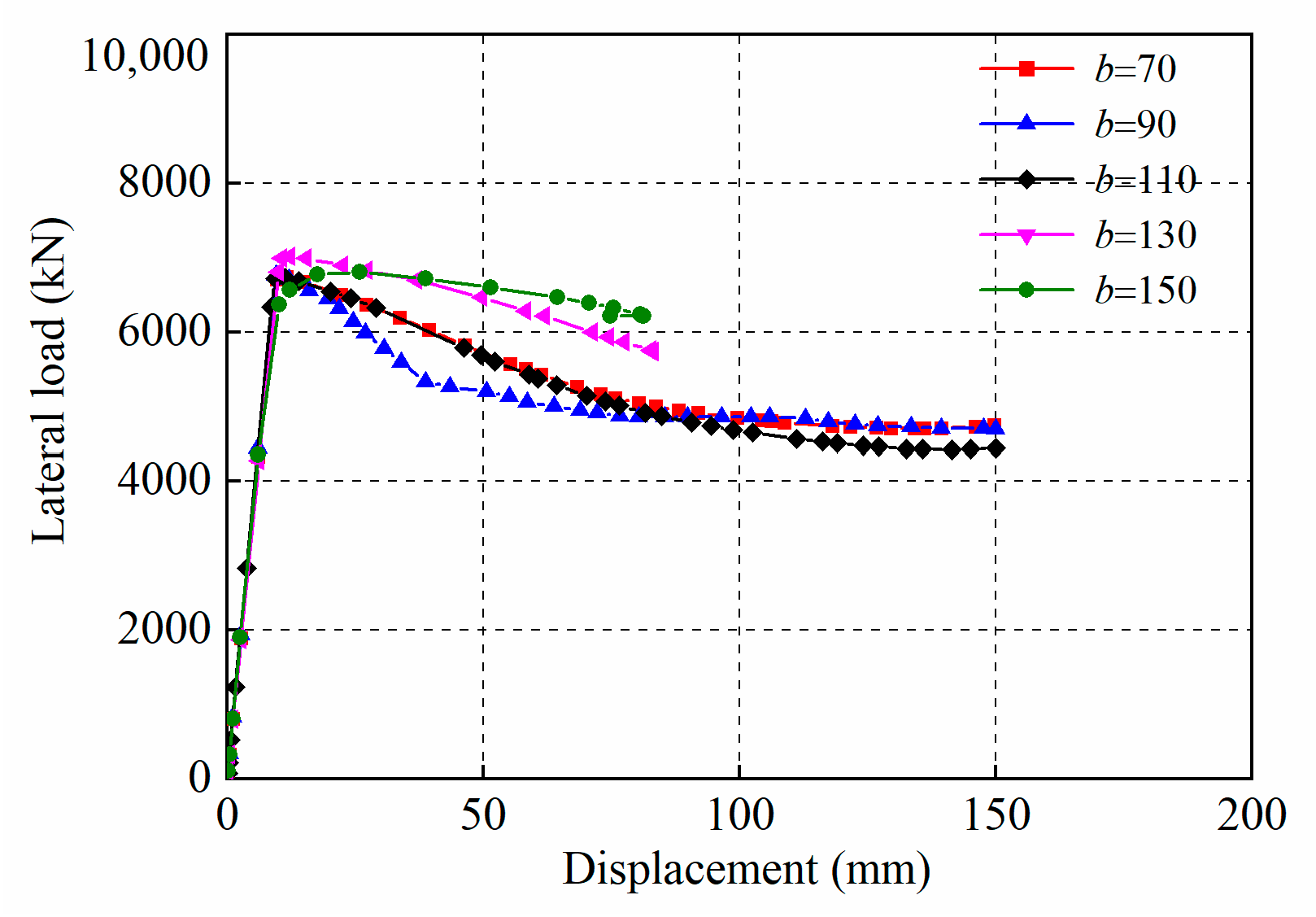
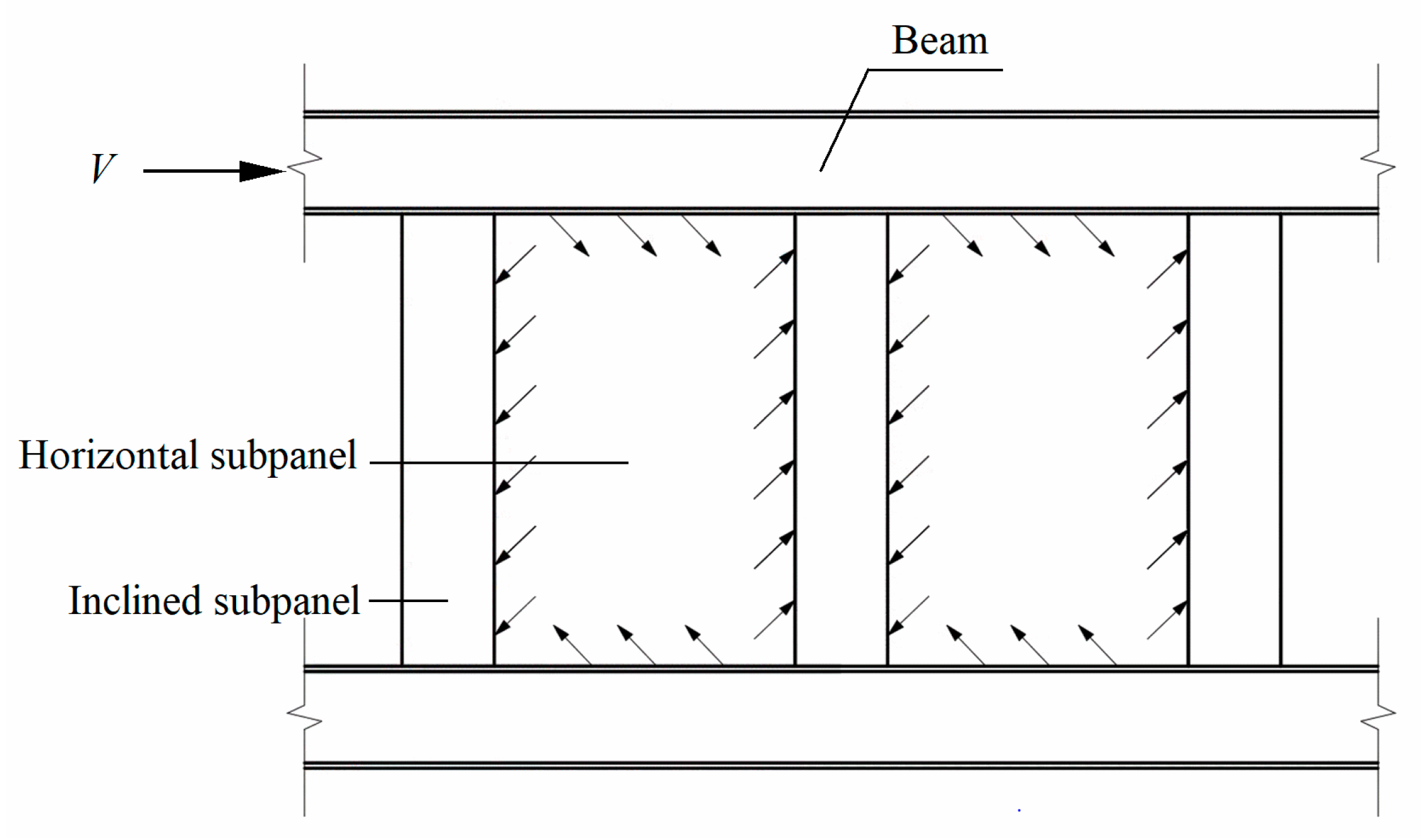
3.4. Horizontal Subpanel Width Effect

The horizontal subpanel width affects the buckling strength and elastic modulus of the CSP. Specimens with horizontal subpanel widths of 70, 90, 110, 130, and 150 mm were established to study the effect of the horizontal subpanel width on the shear performance of the CvSPSWs. The width of the inclined subpanel equaled the width of the horizontal subpanel. The load–displacement curves and load vs. out-of-plane displacement curves of these CvSPSWs are shown in Figure 16 and Figure 17.
Figure 17 shows that the initial shear stiffness of the shear walls is insensitive to the horizontal subpanel width because the width of the CSPs remains unchanged. When the horizontal subpanel is in the range of 70–130 mm, the buckling and ultimate capacity of the CSP increase with an increase in the horizontal subpanel width. However, when the horizontal subpanel width reaches 150 mm, the ultimate and buckling capacities begin to decrease. This is because the constraints from the inclined subpanels decrease due to the larger span of the inclined subpanels with the increase in inclined panels. The out-of-plane deformation of the CSPs with a horizontal panel width b = 110 and 130 mm confirms the situation, as shown in Figure 18. The tension field of the CvSPSW with the horizontal subpanel width b = 110 mm develops more fully than that of the CvSPSW with the horizontal subpanel width b = 130 mm, as shown in Figure 18.

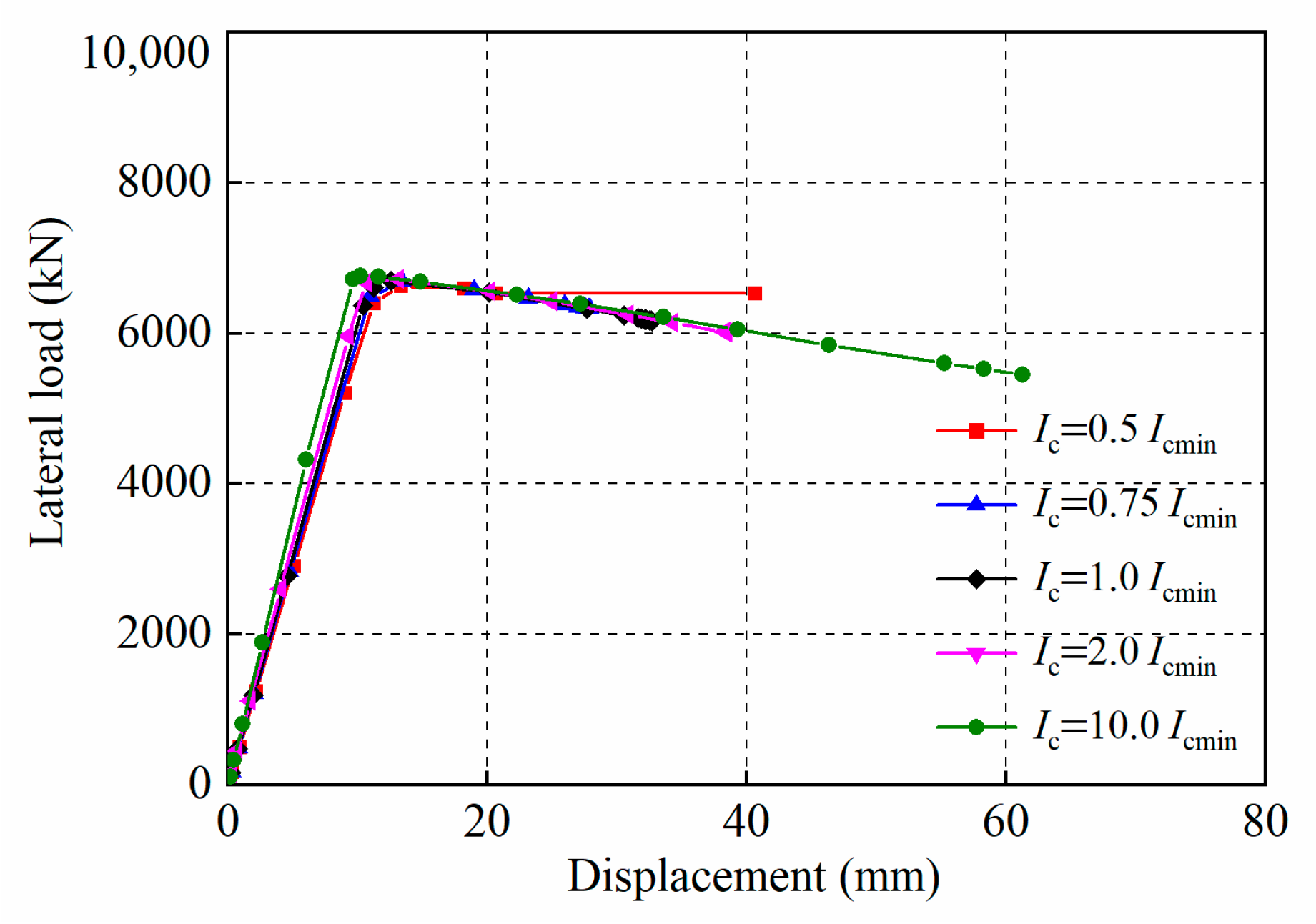
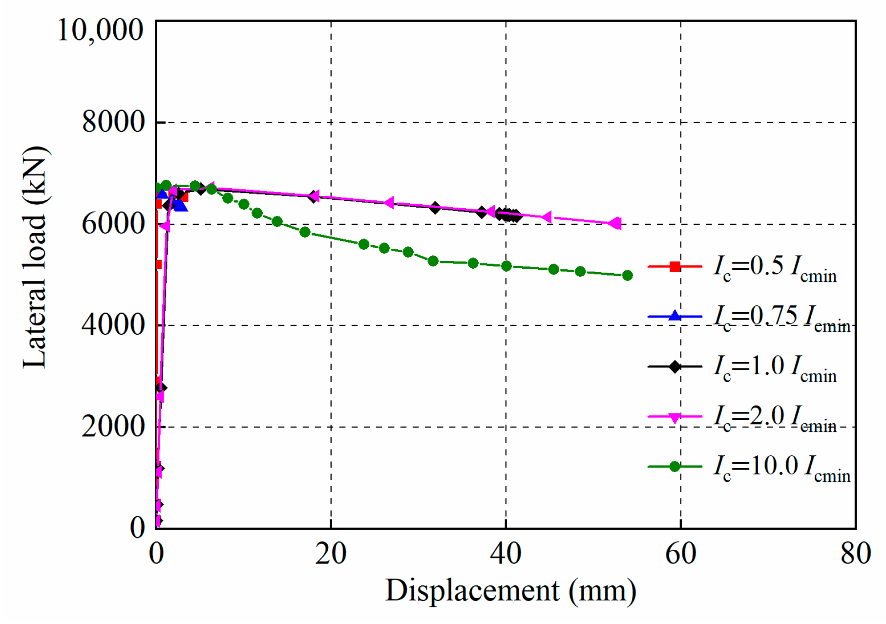
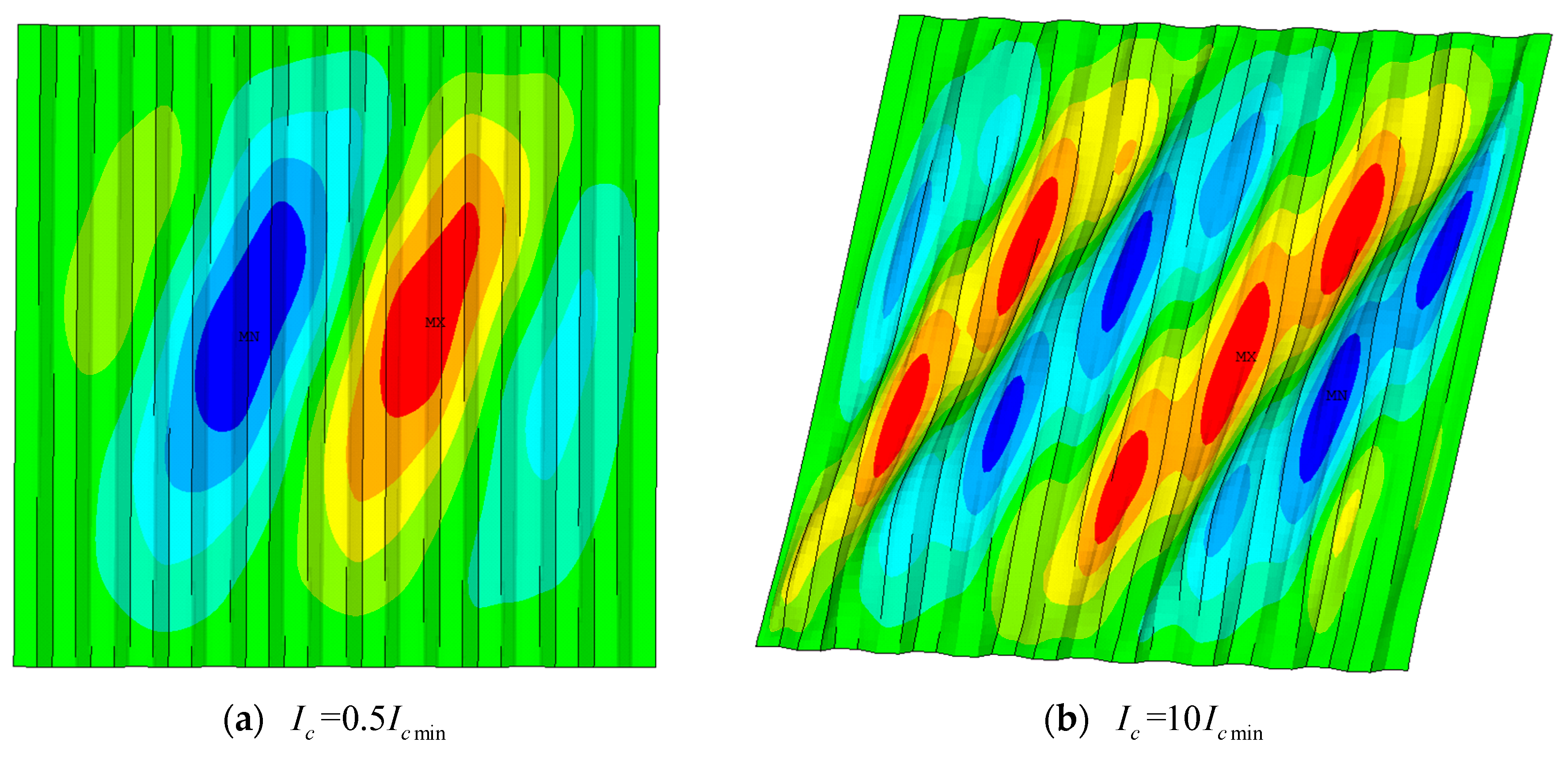
3.5. Surrounding Frame Stiffness Effect

As boundary conditions for the infilled plate, the surrounding frame stiffness plays an important role in the buckling strength and tension field of the infilled plates in the shear wall. The stiffness limit of the surrounding column was suggested as Equation (1), which is based on the tension field of flat steel plate shear walls (FSPSWs) with thin infilled plates [47].
I c min 0.0031 t w d s 4 / b s
where d s is the distance between adjacent beams and b s is the distance between adjacent columns.
The development of the tension field of CvSPSWs differs from that of FSPSWs. In order to investigate the column stiffness effect on the shear performance of CvSPSWs, five specimens of CvSPSWs were developed with surrounding column stiffnesses of 0.5 I c min , 0.75 I c min , 1.5 I c min , 2.0 I c min , and 10.0 I c min . The detailed parameters of the column sections are listed in Table 1. Figure 19 shows the load–displacement curves of CSPs with different column stiffnesses. Figure 20 shows the load vs. out-of-plane displacement curves of CSPSWs with different column stiffnesses.
From Figure 19, the initial lateral stiffness and ultimate strength of the CSPs increase with the increase in column stiffness. Figure 21 shows the buckling strength vs. column stiffness curves. The buckling strengths of the CSPs are 206.9, 209.2, 209.9, 211.2, and 211.3 MPa, respectively, when the column stiffnesses are 0.5 I c min , 0.75 I c min , I c min , 1.5 I c min , 2.0 I c min , and 10.0 I c min . It is indicated that the buckling strength of the CSP has a positive relationship with the surrounding frame stiffness.
In addition, Figure 22 shows the failure modes of the CSPs with different column stiffnesses. From the figure, the tension field in the CSP with column stiffness 10 I c min develops more fully than that of the CSP with column stiffness 0.5 I c min .

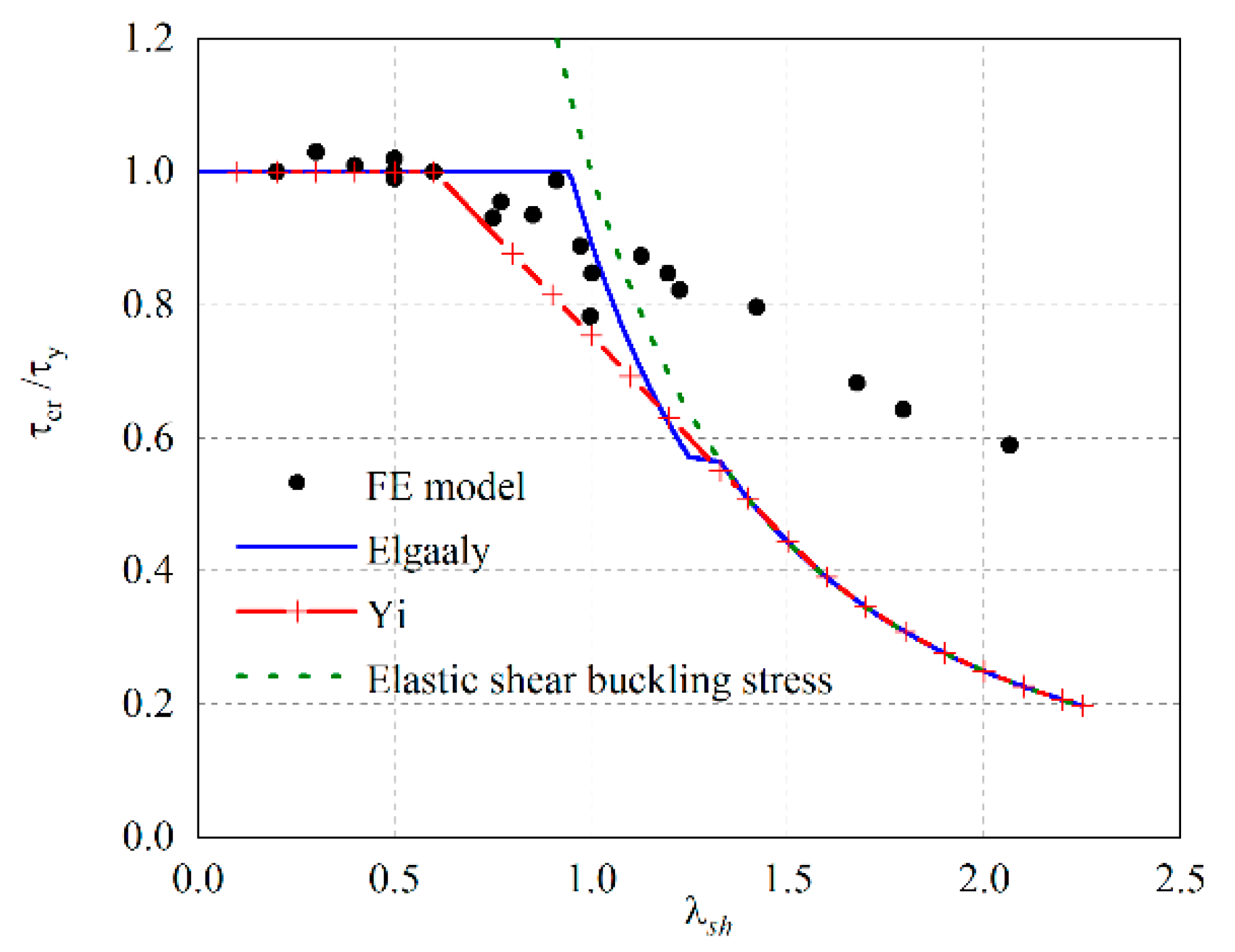
4. Buckling Strength and Section Stiffness of the Inclined Subpanel Effect

According to Section 3, the buckling strength of a CvSPSW has a close association with inclined subpanels. The inclined subpanels are regarded as the stiffeners of the horizontal subpanels, which can make the tension field of CSPs develop more fully when the stiffeners have enough stiffness in the CvSPSWs with interactive buckling of CSPs.
The buckling strength for the CSP in the ChSPSW τ c r h is usually obtained by Equations (2)–(6) [48,49], based on the slenderness ratio of the CSP λ s h .
τ c r h τ y = 1 λ s h < 0.6 1 0.614 λ s h 0.6 0.6 λ s h < 2 1 / λ s h 2 λ s h 2
λ s h = ( τ y / τ c r E ) 0.5
τ c r E = τ c r , G E × τ c r , L E τ c r , G E + τ c r , L E
τ c r , L E = [ 5 . 34 + 4 ( b B ) 2 ] π 2 E w 12 ( 1 - μ 2 ) ( t w b ) 2
τ c r , G E = 36 β E w 1 12 ( 1 μ 2 ) 1 / 4 h r t w 2 + 1 6 η 3 / 4 ( t w B ) 2
where τ c r , G E and τ c r , L E represent the elastic global and local shear buckling strengths of CSPs, β is the global buckling coefficient, B is the CSP width, t w is the CSP thickness, μ is the Poisson ratio, h r is the horizontal projection of the inclined subpanels, E w is the elastic modulus of the material of the CSPs, b is the horizontal subpanel width, and η is the reduction factor of the elastic modulus of the CSPs.
According to the parametric analysis in Section 3, constraints from surrounding frames, the formation mechanism of tension fields in CSPs of CvSPSWs with interactive bucking of CSPs differ from those of the CSPs in ChSPSWs. Further, the buckling stress of CSPs given by Equation (2) provides a lower boundary for the buckling strength of CSPs in the ChSPSWs [48]. Compared with ChSPSWs, the buckling strength and the tension field of the CSPs in CvSPSWs (interactive buckling of CSPs) with large aspect ratios are mainly affected by the constraints from inclined subpanels connected to beams. The results of the above parametric analyses in Figure 14 also show that the buckling strengths of CSPs in CvSPSWs are larger than those of CSPs in ChSPSWs when the shear walls have large aspect ratios. Then, the buckling stress of CSPs in the CvSPSWs with large aspect ratios obtained by Equation (2) will be significantly underestimated, and this phenomenon is proved by Figure 23. From Figure 23, we can see that with the increase in the slenderness ratio λ s h , the underestimation of the buckling strength of the CSPs in the CvSPSWs becomes more severe. Thus, the above predicted formulas for the buckling strength of the CSPs in the ChSPSWs are no longer applicable to predicting the buckling strength of the CSPs in the CvSPSW with interactive buckling of the CSPs. Research on an effective method to predict the buckling strength of the CSP in the CvSPSW with interactive buckling of CSPs is necessary.
The formulas, Equations (7)–(10), are used to predict the shear buckling strength of the webs of beams under shear loads, which takes the tension field of grids between stiffeners in the webs of beams into consideration [50]. The tension field of the CSPs in CvSPSWs under lateral loads is like the tension field of the webs of beams with stiffeners subjected to shear loads, shown in Figure 24. Therefore, it is very necessary to study the application feasibility of the formulas for the buckling strength of the corrugated webs in beams, Equations (7)–(10), in predicting the buckling strength of the CSPs in CvSPSWs under lateral loads.
τ c r = β τ f v
β τ = 1.0 λ s 30 k r 1.5 λ s / ( 60 k r ) 30 k r < λ s 45 k r 33.75 k r / λ s λ s 45 k r
k r = 4 + 5.34 / ( b / H w ) 2 H w / b 1 5.34 + 4 / ( b / H w ) 2 H w / b > 1
λ s = b t w f y 235
where k r is the buckling coefficient of CSPs, β τ is the strength reduction factor, f y is the yield strength of the material of CSPs, f v is the shear strength of the material of CSPs, and H w is the CSP height.
A series of FE models were developed to verify the validity and accuracy of Equation (7) in predicting the buckling strength of the CSPs in CvSPSWs. The FE models for the CvSPSWs considered different horizontal subpanel configurations, height–thickness ratios, and aspect ratios. The details of these models are shown in Table 2. The comparison of the buckling strength of the CSPs in the CvSPSWs between the FE models and Equation (7) is shown in Table 2.
From Table 2, the maximum relative error of the buckling strength between the FE model and Equation (7) is 13% when the height–thickness ratio of the horizontal subpanel λ s is less than 100. When the height–thickness ratio λ s is greater than 100, the maximum relative error is approximately 20%. In the CvSPSW structures, the height–thickness ratio of the horizontal subpanel λ s is usually less than 100. The results show that the results predicted by Equation (7) agree well with those of the FE models when the height–thickness ratio λ s is less than 100. Therefore, it is indicated that Equation (7) can predict the buckling strength of CSPs in the CvSPSWs with good accuracy.
As the stiffeners of CSPs, with proper design of the parameters of CSPs, the inclined subpanels will improve the out-of-plane stiffness of a CSP significantly, and the out-of-plane stiffness of a CSP in a CvSPSW along the direction of lateral loads is greater than that of the CSP in the ChSPSW, as shown in Figure 25 and Figure 26. This is because the out-of-plane bending stiffness of a CSP in a CvSPSW with a large aspect ratio is greater than that of the CSP in a ChSPSW with the same aspect ratio.
The out-of-plane of the bending section moment of inertia of a CSP in a CvSPSW I v x can be expressed as:
I v x = 1 12 B t w 3 + B t w ( h r 2 ) 2 + 1 12 t w h r 3
As the section moment of inertia varies along the height direction of the CSP shown in Figure 26, the equivalent out-of-plane bending section moment of inertia of the CSP in the ChSPSW I h x can be obtained as:
I h x = 1 12 B t w 3 + B t w ( h r 2 ) 2 + 1 12 t w h r 3 ( t w H w )
Equations (11) and (12) show that with the increase in the aspect ratio, the bending section moment of inertia of a CSP in a CvSPSW is gradually greater than that of the CSP in a ChSPSW. This can explain why the buckling strength of a CSP in a CvSPSW with a large aspect ratio is greater than that of a CSP in a ChSPSW with the same large aspect ratio.
However, when the stiffness of the inclined subpanel is small, the inclined subpanel is not helpful for the buckling strength and tension field of the horizontal subpanel. It is indicated that inclined subpanels of CSPs have sufficient stiffness to provide sufficient constraints for the buckling strength and the development of the tension field of CSPs when the inclined subpanels have enough stiffness. The out-of-plane bending stiffness of the inclined panel should be greater than that of the grid between adjacent inclined panels of a CSP in a CvSPSW. Based on the requirements for vertical stiffness of infill plates in the FSPSW [51], the minimum section stiffness of the inclined subpanel for sufficient constraints for the horizontal subpanel of a CSP in a CvSPSW is expressed as:
η x = E w I v i D ζ = 50
where η x is a parameter of the bending stiffness of inclined subpanels, D is the out-of-plane bending stiffness of the section of one grid between inclined panels, and I v i is the out-of-plane area moment of inertia of the inclined subpanels.
Figure 25 shows the equivalent section of a CSP in a CvSPSW. The equivalent area moment of inertia of the inclined subpanels can be obtained as:
D = E w t w 3 12 ( 1 μ 2 )
When the coefficient of the inclined subpanel η x satisfies the requirements of Equation (13), the stiffeners of the inclined subpanels in CSPs can provide sufficient constraints for the horizontal subpanels in CvSPSWs, and the buckling strength of CSPs in CvSPSWs can be predicted by Equation (7). When the coefficient of the inclined subpanel η x cannot satisfy the requirements of Equation (13), the stiffeners of the CSPs cannot provide enough constraints for the buckling strength and full development of the tension field in the CSPs of the CvSPSWs, and the buckling strength of the CSPs can be obtained by Equation (2).

5. Simplified Analytical Model

The simplified analytical model can significantly improve the computational efficiency of the elastoplastic and seismic analyses for shear walls. The PFI model [52], strip model [53], and symmetric strip model [54] are used to simulate the seismic performance of ChSPSWs. However, the shear performance, buckling strength, and formation mechanism of the tension field of a CvSPSW differ from those of a ChSPSW. The application of the simplified analysis methods to the elastic–plastic analysis of CvSPSWs should be investigated. Therefore, it is necessary to investigate an effective simplified model for the elastic–plastic analysis of CvSPSWs. In this section, the PFI model and strip model were adopted to predict the shear behavior of CvSPSWs.

5.1. PFI Model

According to the principle of the virtual work, the initial lateral stiffness of the surrounding frames in CvSPSWs K f can be obtained as [22]:
K f = 1 H 3 6 E 1 I 1 ( 3 ϕ 2 3 ϕ + 1 ) + L H 2 ϕ 2 12 E 2 I 2 + ( 1 ϕ ) 2 H 2 L 12 E 3 3 I 3 3
ϕ = k 1 μ 2 k 2 ( 1 + 3 k 2 )
μ 2 = k 1 k 2 + 6 k 1 + 1
where E 1 is the elastic modulus of the materials of the columns, E 2 and E 3 are the elastic modulus of the materials of the top and bottom beams, I 1 is the area moment of inertia of the columns, I 2 and I 3 are the area moment of inertia of the top and bottom beams, H is the center-to-center distance of adjacent columns, L is the center-to-center distance of adjacent beams, k 1 is the linear stiffness ratio of the top beam to the adjacent column, k 1 = H I 2 / L I 1 , k 2 is the linear stiffness ratio of the bottom beam to the adjacent column, k 2 = H I 3 / L I 1 , and ϕ and μ are non-dimensional parameters.
The initial lateral stiffness of a CSP in a CvSPSW K can be calculated as [51]:
K = ψ K w
The reduction coefficient of the lateral stiffness of a CSP ψ takes the initial imperfection of the CSP into consideration.
ψ = 0.014 ln ( B / H w ) 0.118 ln ( λ ) + 1.24
λ = H w t w 235 f y
where ψ represents the stiffness reduction coefficient of the CSP, λ represents the height–thickness ratio of the CSP, and υ represents the Poisson’s ratio of the materials of the CSP.
According to the principle of virtual work, the initial lateral stiffness of a CSP in a CvSPSW K can be calculated as: [22]
K w = γ H w 3 12 E w I z + 2.4 H w ( 1 + μ ) E w η B t w
where I z is the section moment of inertia of a CSP and η is the shearing-shape coefficient for a CSP.
From Figure 27, the section moment of inertia of a CSP I z can be expressed as:
I z = 1 12 t w B 3 + h r t w d i 2
η = b + c + b b + c + d
where d i is the distance from the ith inclined subpanel to the neutral axis of the CSP and c is the width of an inclined subpanel.
The initial stiffness of a CvSPSW K can be obtained as:
K s = K + K f
The buckling capacity of a CSP can be calculated as:
V c r = τ c r B t w
where τ c r is buckling strength of the CSP, which can be obtained from Equation (7).
The buckling displacement of a CSP can be expressed as:
U c r = V c r K s
The ultimate bearing capacity of a CSP can be obtained from:
V u = ( τ c r + 0.5 σ t y sin 2 θ ) B t w
where θ is the inclination angle of the tension field of the CSP and σ t y is the ultimate tensile stress of the CSP.
The lateral displacement corresponding to the ultimate bearing capacity is obtained as:
U w e = ( τ c r G w + 2 σ t y E w sin 2 θ ) H w
where G is initial shear modulus of a CSP and E w is the elastic modulus of a CSP.
Comparisons of the load–displacement curves between the FE and PFI models are shown in Figure 28. With an increase in the height–thickness ratio and aspect ratio, the differences in the load–displacement curves after peak loads between the PFI and FE models increase. This is because the load–displacement curves of the CSP and frame adopt a three-segment model and a two-segment model, respectively. The PFI cannot simulate the descent segments of the load–displacement curves of the FE models. In general, the PFI model can well capture the initial stiffness, buckling, and ultimate strength of the CvSPSWs. It is indicated that the PFI model can predict the load–displacement curves of the FE models of CvSPSWs with good accuracy.

5.2. Equivalent Bracing Model

Based on the strip model [49] and the symmetric strip model [50], an equivalent strip model for a CvSPSW was proposed, shown in Figure 29. In the model, there are two rigid beams, two columns, one tensile bracing, and one compressive bracing. The tensile and compressive bracings are used to simulate the tensile and compressive behavior of CSPs in the CvSPSWs.
The inclined angle of the tensile bracing is obtained as:
α = a r tan ( H w B )
The areas of the tensile and compressive bracings can be expressed as:
A l = K B cos 2 α 2 E w c o s 3 α
In the model, the compressive capacity of the CSPs cannot be ignored. The constitutive relation of the compressive bracing adopted a two-segment model, and the constitutive relation of the tensile bracing adopted a three-segment model. The constitutive relations of the tensile and compressive bracings are shown in Figure 30.
The initial lateral stiffness of a CSP in a CvSPSW K can be obtained from Equation (19). The yield stress of the tensile bracing can be obtained as:
σ y t = V y t E w cos 2 α K B
The yield stain of the tensile bracing ε y t can be expressed as:
ε y t = Δ y t cos 2 α B
Δ y t = V y t K
V y t = τ y B t w
According to the analyses in Section 3, the compressive stress of CSPs cannot be ignored. The yield stress of the compressive bracing adopted the shear buckling stress predicted by Equation (7) or (2). Then, the corresponding compressive yield capacity and the yield strain of the compressive bracing can be calculated as:
σ y c = V y c E w cos 2 α K B
V y c = τ c r B t w
ε y c = Δ y c cos 2 α B
Δ y c = V y c K
where τ c r is the shear buckling stress of the CSP.
The lateral stiffness in the inelastic hardening regions of a CSP K h can be adopted at 10% of the initial stiffness of the CSP, which can be expressed as:
K h = 0.1 K
The ultimate load of the CSP V u can be obtained as:
V u = τ u B t w
In addition, the ultimate tensile stress of the tensile bracing is expressed as:
σ u t = V u E w cos 2 α K   B
The strain corresponding to the ultimate tensile stress of the tensile bracing is calculated as:
ε u t = Δ u cos 2 α B
Δ u = V y K + ( V u V y ) K h
The elastic modulus of the tensile bracing in the strain-hardening regions can be expressed as:
E h = σ u t σ y t ε u t ε y t
Comparisons of the load–displacement curves between the test [45] and the modified strip model are shown in Figure 31. The ultimate load of the test is larger than that of the test. This is because the ultimate load of the test is influenced by manufacturing errors and lateral supports. After the peak load, the difference between the strip model and the test increases. This is because the strip model cannot simulate the tears after the peak load, which continuously occur after the peak load. In general, Figure 31 shows that the results simulated by the equivalent bracing model agree well with those of the test. It is indicated that the modified strip model can predict the shear performance of the CvSPSW with good accuracy.

6. Conclusions

This paper investigates the shear behavior of CvSPSWs with interactive buckling of CSPs under lateral loads, and the loading mechanism and analytical method for the CvSPSW with interactive buckling of the CSP were investigated. The effects of the concerned parameters on the shear performance of CvSPSWs were discussed. Based on the results of the parametric analysis and the results for webs of beams, an estimating formula for predicting the buckling strength of a CSP in a CvSPSW with interactive buckling of a CSP was proposed. In addition, simplified analytical models for CvSPSWs were investigated. The main conclusions are as follows:
(1) The CvSPSWs with interactive buckling of CSPs show large stiffness, buckling strength, and good displacement ductility. As the stiffeners of horizontal subpanels, the stiffness of the inclined subpanels influences the buckling strength and development of the tension field in the CSP of the CvSPSW. In particular, when the CvSPSWs have large aspect ratios, the constraints from the surrounding columns become weak, while the inclined subpanel connected to beams provides additional constraints for the CSPs in the CvSPSWs, which makes the tension field of the CSPs in the CvSPSWs with large aspect ratios develop more fully than those of the CSPs in the ChSPSWs with the same aspect ratios.
(2) The connection types between surrounding frames and CSPs play an important part in the shear behavior of shear walls. The buckling and ultimate strength of the ChSPSW with two-side connections decreased significantly compared to those of the ChSPSW with four-side connections. It is indicated that the ChSPSW with two-side connections cannot be directly used in shear wall structures with openings, which should be strengthened in future designs. The CvSPSW with two-side connections has greater strength than that of the ChSPSW, and the CvSPSW is an optional lateral resisting system for shear walls with openings.
(3) The initial stiffness and ultimate strength of a CSP increase with an increase in the height–thickness ratio. The aspect ratio is usually suggested to be less than 2.0 in the ChSPSWs without stiffeners for the strength and stiffness requirements of codes, while the CvSPSWs have a larger strength and good displacement ductility with the same large aspect ratios. It is this characteristic that makes the layout of openings in CvSPSWs flexible without taking the strength and stiffness reductions due to the weak constraints from surrounding columns or large openings into consideration. The initial stiffness of the CSP is insensitive to the horizontal subpanel width. The horizontal subpanel width influences buckling and ultimate strength and decreases the rate of bearing capacity after peak loads. With the increase in the surrounding frame stiffness, the buckling and ultimate strength increase, and the tension field of the CSP develops more fully.
(4) The buckling strength formula for the CSPs in the ChSPSW, Equation (2), will significantly underestimate the buckling strength formula of the CSPs in the CvSPSW. When the coefficient of the inclined subpanel η x satisfies requirements of Equation (13), the inclined subpanels in CSPs can provide enough constraints for the horizontal subpanels in CvSPSWs, and the buckling strength of CSPs in CvSPSWs can be predicted by Equation (7). The results show that Equation (7) can well predict the buckling strength of CSPs in CvSPSWs with interactive buckling of CSPs.
(5) The PFI and equivalent bracing models are used to simplify the elastoplastic analysis for CvSPSWs. In the two models, the compressive capacity of the CSPs and the strength enhancement of the CSPs from the inclined subpanels are taken into consideration. The results show that the PFI and modified strip models can simulate the shear performance of CvSPSWs with good accuracy.
This paper investigates the shear behavior and analytical method of CvSPSWs with inelastic buckling of the infilled plates, and the seismic performance of the loading tests of CvSPSWs is essential. In addition to these, continuum mechanics can provide new insights into the static and seismic performances of CbvSPSWs.

Author Contributions

Software, Q.C.; Formal analysis, Q.C.; Investigation, Q.C.; Writing—original draft, Q.C.; Supervision, J.H.; Project administration, J.H.; Funding acquisition, J.H. All authors have read and agreed to the published version of the manuscript.

Funding

This work is supported by the National 13th Five-Year Science and Technology Support Program of China (Project No: 2016YFB1200602). Their support is acknowledged with thanks.

Data Availability Statement

Not applicable.

Conflicts of Interest

The authors declare no conflict of interest.

References

  1. Wang, W.; Quan, C.-C.; Li, Y.; Zhen, G.-K.; Zhao, H.-T. Experimental study and numerical simulation analysis on seismic performance of corrugated steel-plate shear wall with replaceable bottom corner dampers. Soil Dyn. Earthq. Eng. 2022, 152, 107061. [Google Scholar]
  2. Kalali, H.; Ghazijahani, T.G.; Hajsadeghi, M.; Zirakian, T.; Alaee, F.J. Numerical study on steel shear walls with sinusoidal corrugated plates. Solids Struct. 2016, 13, 2502–2514. [Google Scholar] [CrossRef]
  3. Dou, C.; Pi, Y.L.; Gao, W. Shear resistance and post-buckling behavior of corrugated panels in steel plate shear walls. Thin-Walled Struct. 2018, 131, 816–826. [Google Scholar]
  4. Zhang, W.; Mandavian, M.; Yu, C. Lateral strength and deflection of cold-formed steel shear walls using corrugated sheathing. J. Constr. Steel Res. 2018, 148, 399–408. [Google Scholar] [CrossRef]
  5. Yu, Y.; Chen, Z. Rigidity of corrugated plate sidewalls and its effect on the modular structural design. Eng. Struct. 2018, 175, 191–200. [Google Scholar]
  6. Wang, W.; Ren, Y.; Lu, Z.; Song, J.; Han, B.; Zhou, Y. Experimental study of the hysteretic behaviour of corrugated steel plate shear walls and steel plate reinforced concrete composite shear walls. J. Constr. Steel Res. 2019, 160, 136–152. [Google Scholar]
  7. Zhao, Q.; Qiu, J.; Hao, B.; Hao, B.; Wang, Q. Lateral behaviour of vertically-corrugated Steel plate shear walls connected with beams only. J. Tianjin Univ. (Sci. Technol.) 2019, 2, 46–53. (In Chinese) [Google Scholar]
  8. Emami, F.; Mofid, M.; Vafai, A. Experimental study on cyclic behaviour of trapezoidally corrugated steel shear walls. Eng. Struct. 2013, 48, 750–762. [Google Scholar]
  9. Shon, S.; Yoo, M.; Lee, S. An experimental study on the shear hysteresis and energy dissipation of the steel frame with a trapezoidal-corrugated steel plate. Materials 2017, 10, 83–97. [Google Scholar]
  10. Luo, Q.; Wang, W.; Sun, Z.; Xu, S.; Wang, B. Seismic performance analysis of corrugated-steel-plate composite shear wall based on corner failure. J. Constr. Steel Res. 2021, 180, 106606. [Google Scholar] [CrossRef]
  11. Kalali, H.; Hajsadeghi, M.; Zirakian, T.; Alaee, F.J. Hysteretic performance of SPSWs with trapezoidally horizontal corrugated web-plates. Steel Compos. Struct. 2015, 19, 277–292. [Google Scholar]
  12. Farzampour, A.; Mansouri, I.; Lee, C.H.; Sim, H.B.; Hu, J.W. Analysis and design recommendations for corrugated steel plate shear walls with a reduced beam section. Thin-Walled Struct. 2018, 132, 658–666. [Google Scholar]
  13. Bahrebar, M.; Kabir, M.; Hajsadeghi, M. Structural performance of steel plate shear walls with trapezoidal corrugations and centrally-placed square perforations. Int. Steel Struct. 2016, 16, 845–855. [Google Scholar]
  14. Hosseinzadeh, L.; Mofid, M.; Aziminejad, A.; Emami, F. Elastic interactive buckling strength of corrugated steel shear wall under pure shear force. Struct. Des. Tall Spec. Build. 2017, 26, e1357. [Google Scholar] [CrossRef]
  15. Zhao, Q.; Qiu, J.; Zhao, Y.; Cheng, Y. Performance-Based Seismic Design of Corrugated Steel Plate Shear Walls. KSCE J. Civ. Eng. 2022, 26, 3486–3503. [Google Scholar]
  16. Tong, J.; Guo, Y. Elastic buckling behavior of steel trapezoidal corrugated shear walls with vertical stiffeners. Thin-Walled Struct. 2015, 95, 31–39. [Google Scholar]
  17. Farzampour, A.; Laman, J.; Mofid, M. Behavior prediction of corrugated steel plate shear walls with openings. Constr. Steel Res. 2015, 114, 258–268. [Google Scholar] [CrossRef]
  18. Cao, Q.; Huang, J. Experimental study and numerical simulation of corrugated steel plate shear walls subjected to cyclic loads. J. Thin-Walled Struct. 2018, 127, 306–317. [Google Scholar]
  19. Yan, J.; Ding, Y.; Zong, L.; Li, Z.; Dai, X. Analytical and numerical studies on steel columns with novel connections in modular construction. Int. J. Steel Struct. 2017, 17, 1613–1626. [Google Scholar]
  20. Deng, E.-F.; Zong, L.; Wang, H.-P.; Shi, F.-W.; Ding, Y. High efficiency analysis model for corrugated steel plate shear walls in modular steel construction. Thin-Walled Struct. 2020, 156, 106963. [Google Scholar]
  21. Wang, W.; Zhao, T.; Quan, C.; Song, H.L.; Li, Y.; Zhou, Y.X. Shear bearing capacity of vertical corrugated steel plate shear wall with replaceable toe. Zhejiang Daxue Xuebao (Gongxue Ban) 2021, 55, 1407–1418. [Google Scholar]
  22. Feng, L.; Sun, T.; Ou, J. Elastic buckling analysis of steel-strip-stiffened trapezoidal corrugated steel plate shear walls. J. Constr. Steel Res. 2021, 184, 106833. [Google Scholar] [CrossRef]
  23. Huang, S. Experimental Study on Seismic Behavior of Corrugated Steel Shear Walls. Ph.D. Thesis, Xi’an University of Archi-tecture and Technology, Xi’an, China, 2019. (In Chinese). [Google Scholar]
  24. Garbowski, T.; Gajewski, T.; Grabski, J.K. Role of Transverse Shear Modulus in the Performance of Corrugated Materials. Materials 2020, 13, 3791. [Google Scholar] [PubMed]
  25. Garbowski, T.; Gajewski, T.; Grabski, J. The Role of Buckling in the Estimation of Compressive Strength of Corrugated Cardboard Boxes. Materials 2020, 13, 4578. [Google Scholar] [PubMed]
  26. Marek, A.; Garbowski, T. Homogenization of sandwich panels. Comput. Assist. Methods Eng. Sci. 2015, 22, 39–50. [Google Scholar]
  27. Mrówczyński, D.; Knitter-Piątkowska, A.; Garbowski, T. Non-Local Sensitivity Analysis and Numerical Homogenization in Optimal Design of Single-Wall Corrugated Board Packaging. Materials 2022, 15, 720. [Google Scholar]
  28. Staszak, N.; Gajewski, T.; Garbowski, T. Shell-to-Beam Numerical Homogenization of 3D Thin-Walled Perforated Beams. Materials 2022, 15, 1827. [Google Scholar] [CrossRef]
  29. Staszak, N.; Garbowski, T.; Szymczak-Graczyk, A. Solid Truss to Shell Numerical Homogenization of Prefabricated Composite Slabs. Materials 2021, 14, 4120. [Google Scholar] [CrossRef]
  30. Biancolini, M. Evaluation of equivalent stiffness properties of corrugated board. Materials 2005, 69, 322–328. [Google Scholar] [CrossRef]
  31. Garbowski, T.; Jarmuszczak, M. Homogenization of corrugated paperboard. Part 1. Analytical homogenization. Pol. Pap. Rev. 2014, 70, 345–349. (In Polish) [Google Scholar]
  32. Garbowski, T.; Jarmuszczak, M. Homogenization of corrugated paperboard. Part 2. Numerical homogenization. Pol. Pap. Rev. 2014, 70, 390–394. (In Polish) [Google Scholar]
  33. Wu, Q.; Chen, H.; Gao, W. Nonlocal strain gradient forced vibrations of FG-GPLRC nanocomposite microbeams. Eng. Comput. 2020, 36, 1739–1750. [Google Scholar] [CrossRef]
  34. Fan, F.; Kiani, K. A rigorously analytical exploration of vibrations of arbitrarily shaped multi-layered nanomembranes from different materials. Int. J. Mech. Sci. 2021, 206, 106603. [Google Scholar]
  35. Kiani, K.; Pakdaman, H. On the nonlocality of bilateral vibrations of single-layered membranes from vertically aligned double-walled carbon nanotubes. Phys. Scr. 2020, 95, 035221. [Google Scholar] [CrossRef]
  36. Karimiasl, M.; Ebrahimi, F.; Mahesh, V. On nonlinear vibration of sandwiched polymer- CNT/GPL-fiber nanocomposite nanoshells. Thin-Walled Struct. 2020, 146, 106431. [Google Scholar] [CrossRef]
  37. Kiani, K.; Pakdaman, H. Bilaterally nonlocal dynamics of layer-by-layer assembly of double-walled carbon nanotubes accounting for intertube rigorous van der Waals forces. Eur. J. Mech. A/Solids 2020, 80, 103876. [Google Scholar] [CrossRef]
  38. Yuan, Y.; Zhao, K.; Zhao, Y.; Kiani, K. Nonlocal-integro-vibro analysis of vertically aligned monolayered nonuniform FGM nanorods. Steel Compos. Struct. 2020, 37, 551–569. [Google Scholar]
  39. Tong, J.; Chen, P.; Zhao, J.; Zhao, B. Fracture test of nanocomposite ceramics under ultrasonic vibration based on nonlocal theory. Ceram. Int. 2019, 45, 528–537. [Google Scholar] [CrossRef]
  40. Yu, G.; Kiani, K.; Roshan, M. Dynamic analysis of multiple-nanobeam-systems acted upon by multiple moving nanoparticles accounting for nonlocality, lag, and lateral inertia. Appl. Math. Model. 2022, 108, 326–354. [Google Scholar] [CrossRef]
  41. Kiani, K. Nonlocal and shear effects on column buckling of single-layered membranes from stocky single-walled carbon nanotubes. Compos. B Eng. 2015, 79, 535–552. [Google Scholar] [CrossRef]
  42. Tocci, M.; Fantuzzi, N.; Fabbrocino, F.; Luciano, R. Hygro-thermal vibrations and buckling of laminated nanoplates via nonlocal strain gradient theory. Compos. Struct. 2021, 262, 197–206. [Google Scholar]
  43. Kiani, K. Free vibration of in-plane-aligned membranes of single-walled carbon nanotubes in the presence of in-plane-unidirectional magnetic fields. JVC/J. Vib. Control. 2016, 22, 3736–3766. [Google Scholar] [CrossRef]
  44. Kiani, K. Nonlocal free dynamic analysis of periodic arrays of single-walled carbon nanotubes in the presence of longitudinal thermal and magnetic fields. Comput. Math. Appl. 2018, 75, 3849–3872. [Google Scholar] [CrossRef]
  45. Zhao, Q.; Qiu, J.; Li, N.; Li, Z. Experimental study on seismic performance of trapezoidally corrugated steel plate shear walls. J. Build. Struct. 2018, 39, 112–120. [Google Scholar]
  46. GB 50011; Code for Seismic Design of Buildings. China Ministry of Construction: Beijing, China, 2010. (In Chinese)
  47. Montgomery, C.; Medhekar, M.; Lubell, A.; Prion, H.G.L.; Ventura, C.E.; Rezai, M. Unstiffened steel plate shear wall performance under cyclic loading. Struct. Eng. 2001, 127, 973–975. [Google Scholar] [CrossRef]
  48. Yi, J.; Gil, H.; Youm, K.; Lee, H. Interactive shear buckling behaviour of trapezoidally corrugated steel webs. Eng. Struct. 2008, 30, 1659–1666. [Google Scholar]
  49. John, T.D.; Easley, B. Buckling of light-gage corrugated metal shear diaphragms. Struct. Div. 1969, 95, 3004–3006. [Google Scholar]
  50. Shen, Y.; Chen, Y.; Chen, Y. Steel Structures; Science Press: Beijing, China, 2005. [Google Scholar]
  51. JGJ/T 380-2015; Technical Specification for Steel Plat Shear Walls. China Ministry of Construction: Beijing, China, 2015. (In Chinese)
  52. Sabouri-Ghomi, S.; Ventura, C.; Kharrazi, M. Shear Analysis and Design of Ductile Steel Plate Walls. J. Struct. Eng. 2005, 131, 878–889. [Google Scholar] [CrossRef]
  53. Berman, J.; Bruneau, M. Plastic Analysis and Design of Steel Plate Shear Walls. J. Struct. Eng. 2003, 129, 695–697. [Google Scholar] [CrossRef]
  54. Shishkin, J.; Ver, R.; Grondin, G. Analysis of Steel Plate Shear Walls Using the Modified Strip Model; Department of Civil and Environmental Engineering, University of Alberta: Edmonton, AB, Canada, 2005. [Google Scholar]
Figure 1. Profile of a CSP.
Buildings 13 02184 g001
Figure 2. Configuration of a CvSPSW.
Buildings 13 02184 g002
Figure 3. Meshed FE model for a CvSPSW.
Buildings 13 02184 g003
Figure 4. Mesh sensitivity analyses.
Buildings 13 02184 g004
Figure 5. Comparison of load–displacement curves between FE model and test.
Buildings 13 02184 g005
Figure 6. Comparisons of load–displacement curves.
Buildings 13 02184 g006
Figure 7. Comparisons of buckling strength vs. out-of-plane displacement curves.
Buildings 13 02184 g007
Figure 8. Out-of-plane deformation of CvSPSW and ChSPSW. (a) CvSPSW with four-side connections; (b) ChSPSW four-side connections.
Buildings 13 02184 g008
Figure 9. Load–displacement curves with different height–thickness ratios.
Buildings 13 02184 g009
Figure 10. Load-out-of-plane displacement curves with different height–thickness ratios.
Buildings 13 02184 g010
Figure 11. Out-of-plane deformation of CvSPSWs with different height-to-thickness ratios.
Buildings 13 02184 g011
Figure 12. Load–displacement curves of CSPSWs with different aspect ratios.
Buildings 13 02184 g012
Figure 13. Load vs. out-of-plane displacement curves with different aspect ratios.
Buildings 13 02184 g013
Figure 14. Buckling stress vs. aspect ratio curves in CvSPSWs and ChSPSWs.
Buildings 13 02184 g014
Figure 15. Out-of-plane deformation of CSPs with different aspect ratios.
Buildings 13 02184 g015
Figure 16. Load–displacement curves of CvSPSWs with different horizontal subpanel widths.
Buildings 13 02184 g016
Figure 17. Load vs. out-of-plane displacement curves with different horizontal subpanel widths.
Buildings 13 02184 g017
Figure 18. Out-of-plane deformation of CSPSWs with different horizontal subpanel width.
Buildings 13 02184 g018
Figure 19. Load–displacement curves of CvSPSWs with different column stiffnesses.
Buildings 13 02184 g019
Figure 20. Load vs. out-of-plane displacement curves with different column stiffnesses.
Buildings 13 02184 g020
Figure 21. Buckling strength vs. column stiffness ratio.
Buildings 13 02184 g021
Figure 22. Out-of-plane deformation of CSPSWs with different ccolumn stiffness.
Buildings 13 02184 g022
Figure 23. Buckling strength of the CSP vs. slenderness ratio λ s h curves in CvSPSWs.
Buildings 13 02184 g023
Figure 24. Development mechanism of tension field of CSPs in CvSPSWs.
Buildings 13 02184 g024
Figure 25. Diagram of out-of-plane bending stiffness calculation in a CvSPSW. (a) Front view; (b) Sectional view.
Buildings 13 02184 g025
Figure 26. Diagram of out-of-plane bending stiffness calculation in a ChSPSW. (a) Front view; (b) Sectional view.
Buildings 13 02184 g026
Figure 27. Diagram of section of a CSP in a CvSPSW.
Buildings 13 02184 g027
Figure 28. Comparisons of load–displacement curves between FE and PFI models.
Buildings 13 02184 g028
Figure 29. Diagram of modified strip model for a CvSPSW.
Buildings 13 02184 g029
Figure 30. Constitutive relations of tensile and compressive bracings.
Buildings 13 02184 g030
Figure 31. Comparisons of load–displacement curves between modified strip model and test.
Buildings 13 02184 g031
Table 1. Concerned parameters matrix.
MemberCSP SectionFrame Section
λ H
(mm)
B
(mm)
d
(mm)
b
(mm)
h r
(mm)
Column
(mm)
Beam
(mm)
CvW-1100310031007711077700 × 700 × 70 × 70700 × 700 × 70 × 70
CvW-2200310031007711077700 × 700 × 70 × 70700 × 700 × 70 × 70
CvW-3300310031007711077700 × 700 × 70 × 70700 × 700 × 70 × 70
CvW-4400310031007711077700 × 700 × 70 × 70700 × 700 × 70 × 70
CvW-5500310031007711077700 × 700 × 70 × 70700 × 700 × 70 × 70
CvW-6600310031007711077700 × 700 × 70 × 70700 × 700 × 70 × 70
CvW-7800310031007711077700 × 700 × 70 × 70700 × 700 × 70 × 70
CvW-81500310031007711077700 × 700 × 70 × 70700 × 700 × 70 × 70
CvW-9300310015507711077970 × 970 × 97 × 97970 × 970 × 97 × 97
CvW-10300310046507711077970 × 970 × 97 × 97970 × 970 × 97 × 97
CvW-11300310062007711077970 × 970 × 97 × 97970 × 970 × 97 × 97
CvW-12300310077507711077970 × 970 × 97 × 97970 × 970 × 97 × 97
CvW-13300310093007711077970 × 970 × 97 × 97970 × 970 × 97 × 97
CvW-1430031003100497049700 × 700 × 70 × 70700 × 700 × 70 × 70
CvW-1530031003100639063700 × 700 × 70 × 70700 × 700 × 70 × 70
CvW-16300310031009113091700 × 700 × 70 × 70700 × 700 × 70 × 70
CvW-1730031003100106150106700 × 700 × 70 × 70700 × 700 × 70 × 70
CvW-18300310031009511095320 × 320 × 32 × 32320 × 320 × 32 × 32
CvW-19300310031009511095360 × 360 × 36 × 36360 × 360 × 36 × 36
CvW-20300310031009511095380 × 380 × 38 × 38380 × 380 × 38 × 38
CvW-22300310031009511095450 × 450 × 45 × 45450 × 450 × 45 × 45
CvW-23300310031009511095680 × 680 × 68 × 68680 × 680 × 68 × 68
ChW-1300310015507711077970 × 970 × 97 × 97970 × 970 × 97 × 97
ChW-2300310046507711077970 × 970 × 97 × 97970 × 970 × 97 × 97
ChW-3300310062007711077970 × 970 × 97 × 97970 × 970 × 97 × 97
ChW-4300310093007711077970 × 970 × 97 × 97970 × 970 × 97 × 97
Test55011001100453045200 × 200 × 8 × 12250 × 200 × 12 × 14
Table 2. Results of buckling strength of CSPs in CvSPSWs.
MemberCSP SectionBuckling Strength
λ s b
(mm)
d
(mm)
h r
(mm)
B
(mm)
H
(mm)
FE Model
τ c r e / τ y
Theory
τ c r t / τ y
τ c r t / τ c r e
CvW-24131107777310031000.85 0.92 1.08
CvW-2540200141141310029280.96 1.00 1.05
CvW-2648200141141310029280.82 0.77 0.94
CvW-2748400282282310031280.99 1.00 1.01
CvW-2864400282282310031280.961.00 1.04
CvW-2980400282282310031280.93 1.00 1.07
CvW-3097400282282310031280.89 1.00 1.13
CvW-3180400282282310031280.80 0.80 1.00
CvW-32101500353353310039120.85 0.92 1.08
CvW-33141500353353310039120.94 1.00 1.07
CvW-3424600424424310067440.68 0.55 0.81
CvW-3572600424424310067440.810.98 1.15
CvW-3685600424424310067440.87 0.89 1.02
CvW-37145600424424310067441.00 1.00 1.00
CvW-38170600424424310067440.64 0.54 0.83
Disclaimer/Publisher’s Note: The statements, opinions and data contained in all publications are solely those of the individual author(s) and contributor(s) and not of MDPI and/or the editor(s). MDPI and/or the editor(s) disclaim responsibility for any injury to people or property resulting from any ideas, methods, instructions or products referred to in the content.

