1. Introduction
A progressive collapse in structures occurs when an initial local failure, typically due to an unexpected load, triggers further failures leading to a disproportionate partial or total collapse. While there is significant understanding regarding the collapse of frame structures, with established standards and guidelines [
1,
2,
3,
4], studies on progressive collapses in rigid spatial structures like trusses [
5,
6,
7] and single-layer latticed domes [
8,
9,
10] have also advanced. Yet, research on composite flexible-rigid spatial structures is nascent. Suspended domes, a type of these composite structures, amalgamate the advantages of cable domes and single-layer latticed domes. These are favored in large venues like stadiums due to their rigidity, stability, and construction efficiency. However, a failure in their primary structural component, the cable, can prompt a cascading collapse. The dynamic reaction of these flexible cables differs vastly from that of rigid members, necessitating their separate study.
Thus far, there has been limited research on the progressive collapse of suspended-dome structures. Zhang et al. [
11] utilized numerical simulations to reveal that failures of hoop cables and columns make them susceptible to progressive collapses, while the failure of struts, diagonal cables, and upper reticulated dome members exert less impact on the overall structure. Qu et al. [
12] conducted numerical simulations on a real suspended-dome structure, showing that support system failures can lead to extensive local deformations and possible structure failures. Wang et al. [
13] executed a dynamic-impact-effect experiment on a suspended dome influenced by hoop-cable ruptures, capturing the structural member responses. Liu et al. [
14] performed a comparative FE analysis on the collapse resistance of both Levy-type and loop-free suspended domes after an unplanned cable failure. They deduced that loop-free suspended domes offer better collapse resistance and pinpointed the most vital cable in the outermost layer of the cable-strut system. This progressive collapse reliance was linked to the reticulated shell’s bearing capacity and the cable–strut system’s residual strength. Zhao et al. [
15] undertook a progressive collapse test on a 4.2 m diameter Kiewit suspended-dome model, exposing the structural response and local failure propagation when faced with an initial local failure. Xu et al. [
16] proposed a progressive-collapse mechanism for suspended-dome structures, emphasizing a node-buckling mechanism influenced by local spatial grids. A node-buckling model and resistance index were proposed to quantify the anti-collapse capacity and evaluate the sensitivity of hoop cables.
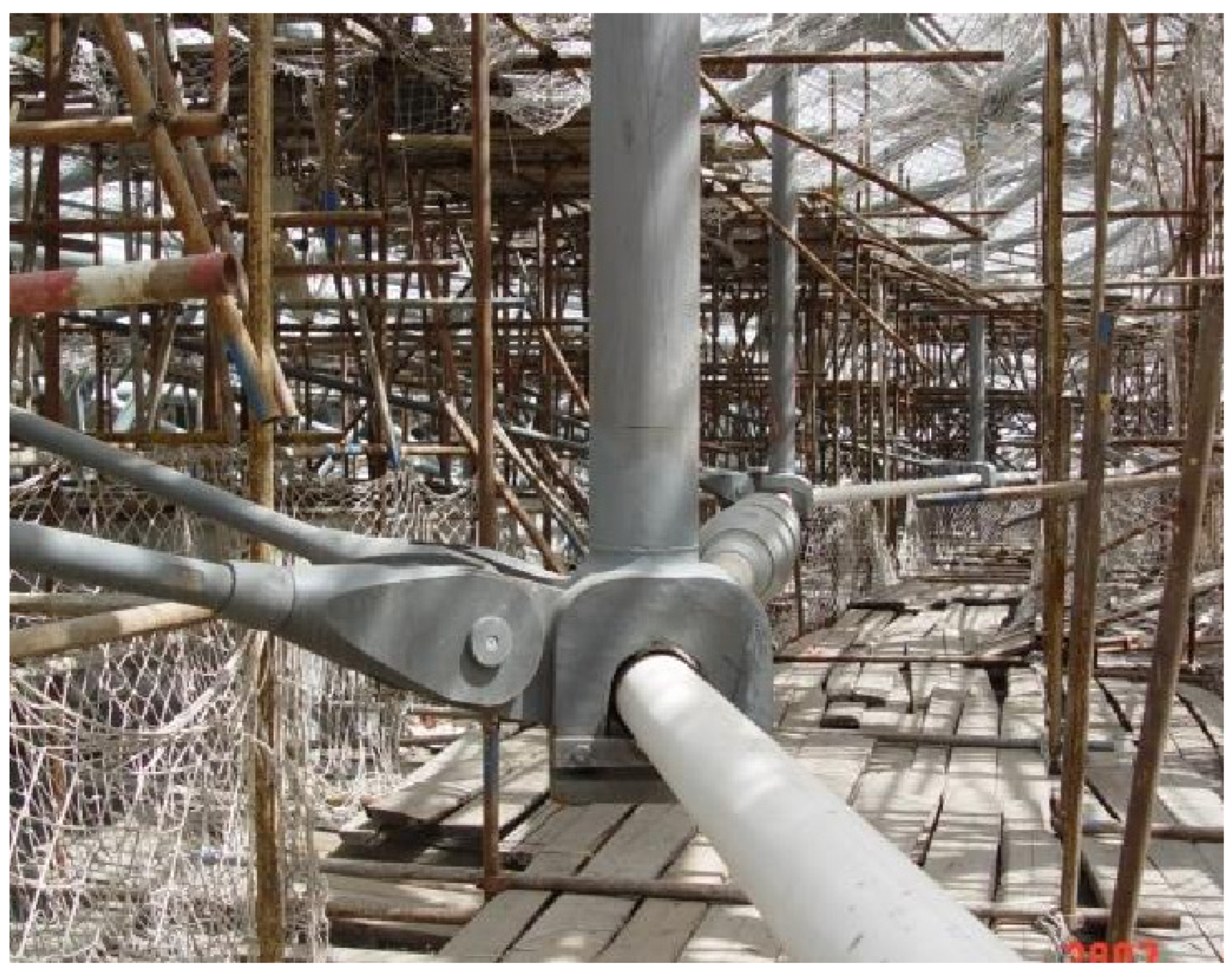
In actual suspended-dome structures, cable-strut joints are classified as either continuous or discontinuous based on their ability to slide along the hoop cable (
Figure 1 and
Figure 2). Discontinuous cable-strut joints align with the assumption of hinge joints. However, for continuous cable-strut joints, the hoop cable and the joint component are fixed together by friction. Under progressive collapse conditions, the imbalance of forces on both sides of the cable-strut joint will significantly increase. This might lead to a slippage of the continuous cable-strut joint, and there is a possibility that the joint could detach from the cable segment. Simplifying continuous cable-strut joints as hinge joints for calculations is clearly inconsistent with reality. However, currently, there have been no experiments studying the impact of different types of cable-strut joints on the progressive collapse resistance of suspended domes. Regarding numerical simulations, cable-strut joints are currently assumed to be of the discontinuous type. The main focus of research on the sliding performance of cable-strut joints is on the prestress loss calculation at the continuous cable-strut joint during the prestressing tensioning process [
17,
18]. Numerical simulations mainly involve static analyses and cannot address the dynamic performance of joints and sliding behavior under large displacements in collapse scenarios [
19,
20,
21,
22,
23]. Hence, current progressive collapse analyses simplify cable-strut joints as hinge joints, which is considerably different from actual structures.
In summary, to investigate the influence of different joint types, especially the sliding and detachment of continuous cable-strut joints, on the anti-collapse performance of suspended domes, this study focuses on both continuous and discontinuous cable-strut joints. Firstly, progressive collapse tests were conducted for two cable-strut joint models, comprehensively examining the force performance of the cable-strut joints during collapse scenarios and exploring their sliding and detachment effects on the progressive collapse of the suspended dome. Subsequently, in the realm of numerical simulations, the next chapter starts from the impact of the sliding and detachment of cable-strut joints on the upper structure. A simplified algorithm suited for the progressive collapse process of suspended-dome structures concerning the sliding and detachment of cable-strut joints is introduced. This algorithm was implemented in the Abaqus subroutine for finite element computations to further research the influence of continuous cable-strut joints on the anti-progressive collapse of suspended domes. Finally, integrated with the node-buckling model and resistance index presented in the literature [
16], we provide a quantitative explanation, from a mechanistic perspective, for the impact of continuous cable-strut joints on the anti-progressive-collapse capability of suspended domes.
2. Test of Cable-Strut Joints under Collapse Conditions
In this chapter, discontinuous cable-strut joints (non-sliding joints) and continuous cable-strut joints (sliding joints) from suspended-dome structures were selected as the subjects of study. The aim was to investigate their load-bearing performance under collapse conditions and to further study their impact on the anti-progressive-collapse capability of the suspended-dome structures.
2.1. Load-Bearing State of Cable-Strut Joints under Collapse Conditions
To study mechanical behaviors such as the slippage and detachment of cable-strut joints during a progressive collapse, it is necessary to first determine the load-bearing state of the cable-strut joints when a progressive collapse occurs in the suspended-dome structure. The selection of the suspended-dome structure is based on the Kiewit-type suspended dome mentioned in references [
15,
16].
For a brief description, the suspended dome was divided into six identical sectors, and the joints and members of the latticed domes, as well as the struts and cables, were labelled according to their location in each sector, as shown in
Figure 3. The labelling principle is explained as follows: (1) the latticed dome joint is labelled as J
m-Xn, where
m,
X, and
n represent the sector number (i.e., 1~6), hoop index (i.e., A~C), and joint number on the hoop, e.g., J1-C2 is the second dome joint on hoop C of sector 1; (2) the latticed dome member starts with M
m-, which is followed by the two joints it connects to, e.g., M1-C1C2 is the member connecting the joints J1-C1 and J1-C2; (3) the cable joint below J
m-Xn is j
m-Xn; (4) the strut connecting J
m-Xn and j
m-Xn is S
m-Xn; (5) the cable starts with C
m and is labelled after the latticed dome member immediately above it, e.g., C1-C1C2 is the hoop cable beneath the dome member M1-C1C2 and connects the cable joints J1-C1 and J1-C2.
Both the test and numerical simulation results [
15,
16] showed that after the failure of the outer hoop cable C1-C2C3, a new tension path was formed in the outer ring of the suspended dome (
Figure 4). At this moment, based on the different load-bearing states of the hoop cables connected at both ends of the cable-strut joint, the joints can be divided into three load-bearing states.
Affiliated Joints: As shown in
Figure 4, the cable-strut joints j1-C2 and j1-C3 have the characteristic that neither end of the hoop cable generates tension, and the members connected to the joint (including struts, hoop cables, and radial cables) are all stress-free. These joints are similar to auxiliary structures, serving as mechanisms attached to the overall structure and have no impact on the structural load. Generally, joints that do not participate in forming a new tension path are considered affiliated joints.
Single-sided Tension Joints: The cable-strut joints j1-C1 and j2-C1 in
Figure 4 are characterized by tension generated on one side of the hoop cable, while the cable force on the other hoop is zero. The tension in the hoop cable is balanced through the radial cable. Since only one side has tension, the unbalanced force in the hoop cables on both sides of the cable-strut joint is the greatest, making it the most likely for the joint to experience slippage in the direction of the cable.
Double-sided Tension Joints: Cable-strut joints like j6-C3, j2-C2, and the other cable-strut joints in
Figure 4 have both sides of the hoop cable under tension. Both sides of the hoop cable and the radial cable achieve a state of force balance. At this time, the unbalanced force between the hoop cables is relatively small, making slippage less likely.
From the above analysis, it can be understood that single-sided tension joints are most prone to slippage in the direction of the cable when the structure undergoes a progressive collapse. Therefore, it is advisable to select joints that are in a single-sided tension state under collapse conditions for research.
2.2. Test Model
Based on the force state of the joint determined in
Section 2.1 and referencing the single-sided tension joint j1-C1, the following joint model was constructed: The cable-strut joint was connected with two hoop cables, HC1 and HC2, as well as three diagonal cables, DC1, DC2, and DC3. It was also linked to the upper dome members DM1, DM2, and DM3 via the strut ST. The upper dome members DM1, DM2, and DM3 were constructed from ø12 × 1 mm St35 seamless steel pipes. All cables were ⌀6 mm steel strands, and the strut was made of 0.45 m long ø12 × 1 mm steel pipes. The pre-tension forces in the hoop cables HC1 and HC2 were 260 N. The yield strength of the steel pipe was 320 MPa, and its tensile strength was 425 MPa. The Young’s Modulus of the cable was 1.67 × 10
5 MPa, and the tensile strength was found to be 1570 MPa. A schematic diagram of the model can be seen in
Figure 5.
There were two test models for the cable-strut joint, classified into a discontinuous joint model and continuous joint model. In the discontinuous joint model, the hoop cables HC1 and HC2 were treated as two separate cable sections, whereas in the continuous joint model, HC1 and HC2 were a single cable section, allowing the joint to slide along the hoop cable.
In the test, by adjusting the pre-tension of the screws between the upper and lower parts of the cable-strut joint, simulations for both the discontinuous and continuous cable-strut joints were achieved. When the screws were fully tightened, it was considered a discontinuous cable-strut joint. When the screws were lightly tightened, it was considered a continuous cable-strut joint. The static friction force value for the continuous cable-strut joint was derived from completed real-life projects: the maximum static friction coefficient between the cable-strut joint and the hoop cable ranged from 0.2 to 0.4. Compared to the pre-stress of the hoop cable, the maximum static friction force in actual projects was approximately 5% of the maximum pre-tension of the hoop cable. Hence, the maximum static friction force in this test was set at 50 N. For both joint models, apart from the different pre-tension forces of the bolts in the cable-strut joints, all other conditions remained the same.
The testing process was divided into three stages: tensioning construction, static load application, and progressive collapse. The initial failure component was the hoop cable HC1. The geometry size, joint design, model fabrication, and breaking device of the other test models were all consistent with those in reference [
15], so they are not elaborated upon here.
3. Test Results
In
Section 2.2, two cable-strut joint test models were constructed. Except for the difference in the ability of the cable-strut joints to slide along the hoop cable, the other conditions of the two models are identical. The aim was to investigate the impact of the sliding performance of the cable-strut joints on the anti-collapse capability of the cable-strut structure. This section will present the different test results and analyze them. During the analysis, we will first examine the changes in the lower cable-strut system, followed by the impact on the upper rigid members.
3.1. Discontinuous Cable-Strut Joint
After the failure of the hoop cable HC1, the remaining hoop cable HC2 and diagonal cables DC1, DC2, and DC3 relaxed rapidly. The axial force in the strut decreased quickly, leading to the failure of the lower cable-strut system. The upper structure collapsed under the load, and by 0.25 s, the hoop cable HC2 and diagonal cable DC1 were completely relaxed. Subsequently, due to the continued descent of the joint, the hoop cable HC2 and diagonal cable DC1 began to tighten again. By 0.47 s, the hoop cable HC2 and diagonal cable DC1 formed a new tension path, and the strut once again provided support to the upper structure. After some oscillations, the structure regained stability. The collapse process is shown in
Figure 6. When an equilibrium configuration was achieved, the vertical displacement of the dome-strut joint was 14.6 cm, which can be seen in
Figure 7.
Starting with the failure of HC1, the collapse process of the model with discontinuous cable-strut joints can be divided into three stages (
Figure 7):
Stage I is from 0–0.25 s and is the initial collapse stage. After the failure of the hoop cable HC1, the cable force in the hoop cable HC2 also decreased rapidly. The diagonal cable DC1 was pulled to the left side by the cable-strut joint, causing its force to first increase and then decrease. By 0.25 s, the forces in the hoop cable HC2 and diagonal cable DC1 had dropped to zero, indicating that the cable-strut system had completely failed. With the failure of the hoop and diagonal cables, the axial force in the strut rapidly decreased, and there was even a brief tension in the strut due to the pull of the cable-strut joint. The strain in the upper dome member DM1 sharply increased and entered yielding (yield strength corresponds to a strain of about 1500 uε).
Stage II, or the formation of a new tension path, is from 0.25–0.47 s. As the dome-strut joint descended, the hoop cable HC2 and diagonal cable DC1 began to tighten again to form a new tension path due to the inability of the discontinuous cable-strut joint to slide. Their force changes were consistent and reached a maximum force of 350 N at 0.47 s. Simultaneously, the axial force in the strut began to compress, and at 0.47 s, the axial strain in the strut reached its peak of −1050 uε. The strain in the upper shell component DM1 continued to increase, with the strain peak at the lower edge reaching −1915 uε. However, as the strut started supporting the upper dome member DM1 again, its strain began to stabilize.
After 0.47 s is Stage III, where the structure, after some oscillations, reached an equilibrium configuration. During this process, the forces in the hoop cable HC2 and diagonal cable DC1 remained synchronized and eventually stabilized around 95 N. The axial strain in the strut eventually stabilized at −380 uε, providing support to the upper dome member again. The strain in the upper dome member DM1 was restricted and did not continue to increase.
In summary, for the model with discontinuous cable-strut joints, when the hoop cable fails, the remaining hoop cables and diagonal cables in the lower supporting system can tighten again to form a new tension path. Through the strut, it can continue to provide support for the dome members. Although the dome-strut joint experienced significant vertical displacements, the discontinuous cable-strut joint model ultimately reached an equilibrium state.
3.2. Continuous Cable-Strut Joint
After the failure of the hoop cable HC1, the remaining cable segments HC2, DC1, DC2, and DC3 quickly slackened and the axial force in the strut rapidly decreased. The lower cable-strut system failed, causing the upper dome to collapse under the load (
Figure 8). Since the cable-strut joint is of a continuous type, after the failure of the hoop cable HC1, the joint slipped along the hoop cable HC2, preventing the cable segment HC2 and cable segment DC1 from tightening again. Eventually, the structure exhibited a complete flipping deformation, and the dome-strut joint fell below the substructure. At 0.62 s, the cable-strut joint fell and hit the substructure. At this point, the upper structure had completely collapsed, with the entire collapse process lasting 0.72 s, as shown in
Figure 8. When the structure was completely flipped, the vertical displacement of the dome-strut joint was about 42.5 cm, which can be seen in
Figure 9.
Figure 9 shows the cable force time history of the hoop cable HC2 and diagonal cable DC1. It can be observed that after the failure of the hoop cable HC1, the tensions in both HC2 and DC1 rapidly reduced to oscillate around 0 N. At 0.62 s, due to the cable-strut joint colliding with the substructure, there was a sudden change in the tensions of HC2 and DC1, but the tension eventually dropped back to 0 N. The reason for this phenomenon is that since this model uses a sliding joint, the cable-strut joint slides along the hoop cable HC2, and there is no formation of a new tension path, as described in
Section 3.1.
From the axial force time history of the strut, it can be seen that after the failure of the hoop cable HC1, the axial force in the strut decreased rapidly. Due to the pulling of the cable-strut joint, the strut remained in tension until 0.62 s when the cable-strut joint hit the substructure, at which point the strut rapidly compressed and buckled, with a maximum axial strain approaching −3900 uε.
From the strain time history at the dome member DM1, it can be observed that after the failure of the hoop cable HC1, the bending moment in the upper member DM1 sharply increased, and the strain was significantly higher than that in the discontinuous cable-strut joint model. Moreover, due to the absence of a new tension path in the lower cable-strut system, its strain kept increasing until the cable-strut joint collided with the substructure at 0.62 s, at which point the structure had completely collapsed.
In summary, for the continuous cable-strut joint model, when the hoop cable fails, the cable-strut joint slides along the remaining hoop cable, preventing the lower cable-strut system from being re-tightened. This causes the upper dome members to completely lose the support of the lower cable-strut system, leading to the collapse of the structure.
4. Numerical Simulation Algorithm
Based on the experimental results from
Section 3, we understand that the type of joint plays a significant role in the collapse resistance of the suspended dome structure. Currently, in numerical analyses, the cable-strut joint is considered as a hinge connection between the strut and the cable for the interrupted type. However, for the continuous type of cable-strut joint, there is not a numerical simulation method that can effectively simulate the slippage and detachment of the joint during the continuous collapse of the structure.
Current research on cable-strut joints primarily focuses on tensioning during the construction process, often using implicit algorithms. Especially regarding the simulation of cable-strut joint slippage, the core approach has been to continually adjust the original lengths of the cables on both sides of the joint, determining the extent of slippage through iterative calculations. Clearly, such methods are not suitable for numerical simulations where the structure undergoes large displacements and rotations during collapse scenarios. At this stage, it is impractical to develop a numerical algorithm suited for rod finite element systems that can account for slippage up to detachment in continuous collapse scenarios.
Therefore, this chapter starts from the force characteristics of suspended domes. It emphasizes the fact that once slippage occurs in the cable-strut joint, the strut can no longer provide effective support for the dome members above. Thus, a new simplified method for simulating the slippage and detachment of cable-strut joints in numerical models is proposed.
4.1. Mechanical Model
Regarding the numerical simulation algorithm for the slippage and detachment of cable-strut joints, this study does not consider the specific mechanical behavior of cable-strut joints’ slippage and detachment. Instead, it focuses on their impact on the upper dome. That is, once the cable-strut joint slips, the connected strut can no longer support the upper dome, which has been experimentally verified.
The occurrence of slippage in the cable-strut joint of the suspended dome structure under collapse conditions is directly related to two factors: the unbalanced force on both sides of the cable-strut joint and the maximum static friction between the joint and the cable. When the unbalanced force is less than or equal to the maximum static friction, the joint will not slide along the cable. In this case, in numerical simulations, the cable-strut joint can be simplified as a hinged joint for calculations. When the unbalanced force exceeds the maximum static friction, the cable-strut joint slides and the strut cannot support the upper dome member. As the upper dome member gradually collapses and the cable slips and detaches, it is assumed that the strut has already failed and cannot participate in the stress redistribution process.
Based on the above idea, this study proposes a numerical simulation algorithm for the slippage and detachment of cable-strut joints during the progressive collapse of suspended-dome structures and implements it through an Abaqus subroutine. The calculation process of the algorithm is as follows:
During modeling, the strut and hoop cable remain hinged. Between the strut and the hinge joint, a connection node is established. The connection node is modeled using beam elements, which are rigidly connected to the strut on the top and hinged to the hoop cable on the bottom, as shown in
Figure 10.
Through the material subroutine, the material model of the connection node is defined and the maximum static friction force Fmax of the joint is set.
Obtain the cable force on both sides of the hinged joint and calculate its difference as the unbalanced force ΔF.
After calculating each increment step, determine whether the cable-strut joint is sliding. If the unbalanced force is less than or equal to the maximum static friction of the cable-strut joint, the joint is considered not to slide and can be calculated as a hinge. If it exceeds the maximum static friction, control the birth and death of the connection node through the material subroutine and delete the connection node. At this point, it is considered that the cable-strut joint has fallen off the hoop cable.
4.2. Implementation of Algorithm Based on Abaqus Subroutine
The cable-strut joint sliding algorithm needs to be implemented in Abaqus with the assistance of the subroutine VUAMP and subroutine VUSDFLD. The subroutine VUAMP is a user-defined amplitude subroutine which is utilized to fetch the forces of the hoop cables on both sides at each increment step. The function variables here are the forces F1 and F2 of the hoop cables on both sides. They are defined as sensor variables output from the main program and fetched using the vGetSensorValue function for each increment step’s value.
When the imbalance force Δ
F on both sides of the cable-strut joint exceeds the joint’s maximum static friction force
Fmax, it is considered that the cable-strut joint has slipped and the connection node has failed. At this point, the connection node needs to be deleted. This requires the combined use of field variables and state variables, using the user subroutine VUSDFLD to change the values of the state variables, thereby controlling the life and death of the unit. In Abaqus, state variables are related to calculations, and they are intermediates or results generated during calculations. An essential application of state variables is to pass and invoke analysis results between different analysis parts. A common application is to control the unit’s deletion status by specifying a particular state variable’s value. Therefore, in the hinged state, both field variables and state variables are defined as 1. When the cable-strut joint slips, the field variable is changed to 2. At this time, the state variable becomes 0, realizing the deletion of the connection node (Abaqus/Explicit stipulates that if the deletion of elements is allowed, the element is deleted when the state variable is 0). The entire algorithm process is shown in
Figure 11, and its main steps are as follows:
During structural modeling, establish a connection node between the strut and the cable-strut joint.
At the beginning of increment step k, use the vGetSensorValue function to call the cable forces in the hoop cables on both sides of the joint and calculate the imbalance force.
Judge the relationship between the imbalance force and the maximum static friction force: if the imbalance force is less than or equal to the maximum static friction force, the connection node is not invalid, and its stress state is considered consistent with the hinge. If the imbalance force exceeds the maximum static friction force, it is considered that the joint has slid and cannot provide vertical support for the upper dome. Therefore, the state variable is reset to zero, and the connection node is deleted.
Perform the calculation for increment step k + 1.
4.3. Algorithm Validation
This section uses the collapse test of the continuous node model from
Section 3.2 as an example to verify the applicability and reliability of the proposed cable-strut joint slippage algorithm in dealing with the progressive collapse of a suspended dome structure. After the failure of the hoop cable HC1, the connection node failed immediately after 0.08 s, indicating that the cable-strut joint slipped in the test. This caused the strut to be unable to provide support for the upper dome, which is consistent with the test phenomenon. Meanwhile, the finite element method’s calculation of the subsequent response of the remaining structure well replicated the experimental process, with the collapse process shown in
Figure 12.
It should be noted that in the test, the progressive collapse process terminated after 0.62 s due to the impact of the cable-strut joint on the substructure. However, by this time, the structure had already undergone a complete flipping deformation. Therefore, the finite element calculations after 0.62 s are invalid, so only the results before 0.62 s are compared here.
Figure 13 shows that, in terms of displacement and strain levels, the finite element calculation results and test results both have a high degree of agreement.
4.4. Progressive Collapse of Suspended Dome with Continuous Cable-Strut Joints
This section uses the collapse analysis model of the suspended-dome structure in [
16] as an example, comparing the impact of discontinuous cable-strut joints and continuous cable-strut joints on the structural anti-collapse capability. Both [
15,
16] show that after the failure of the outer hoop cable C1-C2C3, the suspended-dome structure with discontinuous cable-strut joints will form a new tension path at its outer ring. However, the test results of this article show that with the continuous cable-strut joint, there will be sliding along the direction of the hoop cable at the tensioned node on one side. To balance calculation accuracy and efficiency, only the outer ring cable-strut joints j1-C1 and j1-C4 are set as continuous cable-strut joints. The maximum static friction between the cable-strut joint and the hoop cable is set to 7 kN. The geometric size, material properties, etc., of the model are the same as in the literature [
16], which will not be detailed here. A finite element analysis shows that when the load is set at G = 1.21 kN/m
2, neither the suspended-dome structure with discontinuous cable-strut joints nor the one with continuous cable-strut joints will experience a progressive collapse. To make the influence of the cable-strut joint type on the anti-collapse performance of the suspended-dome structure more evident, we increased the load to 1.4 G = 1.69 kN/m
2.
The numerical simulation results show that the results of using discontinuous cable-strut joints and continuous cable-strut joints are completely different.
Figure 14 shows the equilibrium configuration of the suspended-dome structure with discontinuous cable-strut joints. This is consistent with the results of [
15,
16]. The outer oblique cables C1-C1D2 and C1-C4D4 connect the remaining cable segments to the support, forming a new tension path. At this time, except for the nodes J1-C2 and J1-C3, all other outer ring nodes are re-supported, so the structure does not undergo a progressive collapse.
However, for the suspended-dome structure with continuous cable-strut joints, after the failure of the outer hoop cable C1-C2C3, the structure undergoes a progressive collapse. This process is shown in
Figure 15. The cable-strut joints j1-C1 and j1-C4 dropped due to sliding at 0.1 s because the unbalanced forces on both sides exceeded the maximum static friction between the cable-strut joint and the hoop cable. At this time, it is impossible to form a new tension path at the outer diagonal cables C1-C1D2 and C1-C4D4. The axial force of the struts S1-C1 and S1-C4 quickly drops to zero (
Figure 16), and they cannot provide support for the dome-strut joints J1-C1 and J1-C4, leading to J1-C1, J1-C2, J1-C3, and J1-C4 all becoming unsupported nodes. At this point, the entire upper structure above the outer ring is completely degraded to a single-layer shell structure. This seriously weakens the stability of the local arch centered on J1-C2 and J1-C3, causing the local arch node’s instability and eventually leading to the progressive collapse of the structure. This also confirms the conclusion in
Section 3.2, that is, for the suspended-dome structure with continuous cable-strut joints, the sliding and detachment of the cable-strut joint are extremely detrimental to the formation of a new tension path, making it easier to trigger a progressive collapse of the suspended dome.
5. Theoretical Analysis Based on Resistance Index
Both tests and numerical simulations have confirmed that the sliding performance of cable-strut joints has a significant impact on the anti-collapse bearing capacity of the suspended-dome structure. This section will quantitatively analyze this impact through the node-instability-calculation model and resistance index in the literature [
16].
From the previous analysis, it is known that when the suspended-dome structure adopts a discontinuous cable joint, in the event of the failure of the outer hoop cable, the cable support system can form a new tension path to provide support for the upper dome. At this time, the far end of the hoop dome member adjacent to the unsupported joint regains its support, which can assist in the overall stability of the local arch. For the suspended-dome structure with discontinuous cable-strut joints, the point-instability-calculation model is shown in
Figure 17.
However, when using continuous cable-strut joints, the imbalance force on both sides of the cable-strut joint during the collapse process is much greater than the maximum static friction between the joint and the cable, so the strut joint will slide out and fall off from the hoop cable, leading to the new tension path not being formed. This means that the hoop rod cannot assist in the overall stability of the local arch. For the suspended-dome structure with continuous cable-strut joints, the point-instability-calculation model is shown in
Figure 18.
In summary, the weakening coefficient caused by the sliding and falling off of the cable-strut joint can be expressed as the stability resistance index of the continuous cable-strut joint divided by the stability resistance index of the discontinuous cable-strut joint, as shown in Equation (1), where
n represents the number of diagonal or radial rods connected to the unsupported joints,
E is the modulus of elasticity,
Ai is the cross-sectional area,
Ii is the second moment of area of the cross-section,
li is the member length, and
θi is the tilting angle, as shown in
Figure 18.
Taking the Kiewit suspended-dome model in
Section 4.4 as an example, after the outer hoop cable C1-C2C3 fails, for the model with discontinuous cable-strut joints, the unsupported joint is J1-C2, and there are five dome members to provide support for the joint. For the continuous cable-strut joint, there are four dome members to provide support for the joint. According to Equation (1), the weakening coefficient is 0.81. This indicates that in the event of hoop cable failure, the resistance coefficient of the suspended-dome structure with continuous joints is 81% of that with discontinuous joints, proving that the sliding performance of the cable-strut joints has a significant impact on the collapse-bearing capacity of the suspended dome.
6. Discussion
In this study, through joint tests, numerical simulations, and theoretical analyses, we systematically analyzed the impact of the slippage and detachment of continuous cable-strut joints on the collapse resistance of suspended-dome structures. In essence, the slippage and detachment of continuous cable-strut joints affect the formation of new tension paths in the lower support system of the suspended-dome structure, adversely impacting its collapse resistance.
Compared to previous studies, although reference [
13] compared the different structural responses of suspended-dome structures with different types of cable-strut joints after cable breakage, its diagonal cables were replaced by rods, and the applied load was too small to cause a progressive collapse. Thus, reference [
13] did not address the large deformation process of the cable support system, and the impact of new tension paths on the collapse resistance of suspended-dome structures went unnoticed.
In contrast to earlier studies, this paper is the first to investigate the impact of the slippage and detachment of continuous cable-strut joints on the collapse resistance of suspended-dome structures. This investigation was elaborated on and validated through joint tests, numerical simulation methods, and theoretical analyses, marking the most significant innovation of this study.
Future research directions: The simplified numerical simulation method proposed in this study still has room for improvement. The potential slippage and detachment of cable-strut joints under dynamic conditions have always been a challenge in the study of suspended-dome structures. This paper, focusing on progressive collapses, emphasizes the characteristic where, if the imbalance forces on both sides of the cable-strut joint exceed the maximum static friction, leading to joint slippage, the strut can no longer provide effective support for the upper rigid component. A numerical simulation method for joint slippage and detachment was proposed based on this. However, this method does not accurately simulate the behavior of the slippage and detachment of the joint. Currently, there are two main research directions. One is to model the cable-strut joint using solid elements to consider the friction and slippage between the joint and the cable, balancing computational efficiency with accuracy. The second is to use a component method approach to incorporate the cable-strut joint into the rod finite element analysis system, but this is challenging and warrants further studies.
7. Conclusions
In suspended-dome structures, cable-strut joints can be divided into discontinuous cable-strut joints and continuous cable-strut joints. While discontinuous cable-strut joints can be simplified as hinge joints during calculations, the use of this simplification for continuous cable-strut joints under a broken cable scenario can lead to significant discrepancies between the calculated and actual force-bearing states. Specifically, when a hoop cable breaks, the continuous cable-strut joint might experience slippage or even detachment. This can affect the formation of new tension paths in the cable support system, consequently impacting the progressive collapse resistance of the suspended-dome structure.
To study the influence of different types of cable-strut joints on the progressive collapse resistance of the suspended dome, especially the effects of the slippage and detachment of continuous cable-strut joints, this study employed joint testing, numerical simulations, and theoretical analyses. It was found that during a progressive collapse scenario in a suspended-dome structure, the continuous cable-strut joint can undergo slippage or even detachment, preventing the formation of new tension paths in the underlying cable support system, thereby adversely affecting the structure’s resistance to a progressive collapse. The main conclusions of this article are as follows:
- (1)
Two cable-strut joint test models were constructed. Apart from the cable-strut joints being either discontinuous cable-strut joints or continuous cable-strut joints, all other conditions remained the same. The two cable-strut joint models were subjected to progressive collapse tests under the failure state of the hoop cable. The results showed that the slippage performance of the cable-strut joint had a significant impact on the anti-collapse performance of the suspended domes.
- (2)
In the case of the discontinuous cable-strut joints, when the hoop cable failed, the remaining hoop cables and diagonal cables in the lower cable-strut system could be retightened, forming a new tension path. This allowed the strut to continue providing support to the upper dome members. Consequently, the upper structure regained its support and returned to a stable configuration.
- (3)
Conversely, for the continuous cable-strut joints, when the hoop cable failed, slippage occurred at the remaining hoop cable of the cable-strut joint. This prevented the hoop and diagonal cables in the lower cable-strut system from being retightened, making it impossible for the strut to support the upper dome members. The upper structure completely collapsed due to the total loss of support from the lower cable-strut system.
- (4)
A simplified numerical simulation algorithm for the slippage and detachment of cable-strut joints was proposed. This algorithm does not consider the specific mechanical behavior of joint slippage and detachment but only focuses on the support role of the struts for the upper structure. It was implemented through an Abaqus subroutine in the finite element calculation process, and its accuracy and applicability were validated through test comparisons.
- (5)
A progressive collapse analysis was conducted on the suspended-dome structure using continuous cable-strut joints. The results show that cable-strut joints j1-C1 and j1-C4 slipped and detached along the hoop cable, preventing the formation of new tension paths, leading to the node instability of the local arch and ultimately resulting in the progressive collapse of the structure. For a suspended-dome structure with continuous cable-strut joints, the slippage and detachment of the cable-strut joint are extremely detrimental to the formation of new tension paths, making the structure more prone to a progressive collapse.
- (6)
Using the resistance index proposed in reference [
16], a quantitative analysis of the anti-collapse bearing capacity of suspended-dome structures using both continuous and discontinuous cable-strut joints was carried out. Using the Kiewit-type suspended dome in numerical simulations as an example, it was pointed out that the anti-collapse bearing capacity of the suspended dome using continuous cable-strut joints is 81% of that of the suspended dome with discontinuous cable-strut joints.
Author Contributions
Conceptualization, Z.X.; methodology, D.Z.; software, Z.X.; validation, Z.X.; formal analysis, Z.X.; investigation, Z.X.; resources, D.Z.; data curation, Z.X.; writing—original draft preparation, Z.X.; writing—review and editing, D.Z. All authors have read and agreed to the published version of the manuscript.
Funding
This research was funded by the National Natural Science Foundation of China, grant number 51678432.
Data Availability Statement
The data presented in this study are available on request from the corresponding author.
Conflicts of Interest
The authors declare no conflict of interest.
References
- GSA. Progressive Collapse Analysis and Design Guidelines for New Federal Office Buildings and Major Modernization Projects; General Services Administration: Washington, DC, USA, 2003.
- JISF. Guidelines for Collapse Control Design Construction of Steel Buildings with High Redundancy; Japan Iron and Steel Federation: Tokyo, Japan, 2005; Volume 1. [Google Scholar]
- U.S. Department of Defense. UFC 4-023-03 Design of Buildings to Resist Progressive Collapse; U.S. Department of Defense: Washington, DC, USA, 2009.
- CECS 392—2014; Code for Anti-Collapse Design of Building Structures. China Planning Press: Beijing, China, 2015.
- Chen, Y.; Wang, L.; Yan, S.; Zhao, X. Study on the progressive collapse of large span truss-beam structures induced by initial member break. IABSE Symp. Rep. 2015, 103, 112–119. [Google Scholar]
- Yan, S. Progressive Collapse Research of Large-Span Space Frame Structures. Ph.D. Thesis, Tongji University, Shanghai, China, 2015. [Google Scholar]
- Zhao, X.; Yan, S.; Chen, Y.; Xu, Z. Experimental study on progressive collapse-resistant behavior of planar trusses. Eng. Struct. 2017, 135, 104–116. [Google Scholar] [CrossRef]
- Zhao, X.; Yan, S.; Chen, Y. Comparison of progressive collapse resistance of single-layer latticed domes under different loadings. J. Constr. Steel Res. 2017, 129, 204–214. [Google Scholar] [CrossRef]
- Yan, S.; Zhao, X.; Rasmussen, K.J.; Zhang, H. Identification of critical members for progressive collapse analysis of single-layer latticed domes. Eng. Struct. 2019, 188, 111–120. [Google Scholar]
- Tian, L.; Wei, J.; Huang, Q.; Ju, J. Collapse-resistant performance of long-span single-layer spatial grid structures subjected to equivalent sudden joint loads. J. Struct. Eng. 2021, 147, 04020309. [Google Scholar] [CrossRef]
- Zhang, W.; Zhang, P. Numerical simulation of progressive collapse of suspended-dome structures. In Proceedings of the Twelfth National Conference on Modern Structural Engineering; Tianjin University: Tianjin, China, 2012; pp. 424–429. [Google Scholar]
- Ou, T.; Chen, J.; Tan, J. Progressive collapse resistance analysis on conjoined suspendome structure of Zhaoqing new district stadium. Build. Struct. 2016, 46, 75–79. [Google Scholar]
- Wang, X.; Chen, Z.; Yu, Y.; Liu, H. Numerical and experimental study on loaded suspendome subjected to sudden cable failure. J. Constr. Steel Res. 2017, 137, 358–371. [Google Scholar] [CrossRef]
- Liu, R.; Zou, Y.; Wang, G.; Xue, S. On the Collapse Resistance of the Levy Type and the Loop-Free Suspen-Dome Structures After Accidental Failure of Cables. Int. J. Steel Struct. 2022, 22, 585–596. [Google Scholar] [CrossRef]
- Zhao, X.; Xu, Z.; Yan, S. Collapse-resisting mechanism and damage propagation pattern of suspended-domes following sudden cable loss. J. Constr. Steel Res. 2023, submitted.
- Xu, Z.; Yan, S. Anti-Progressive-Collapse Mechanism of Suspended-Dome Structures Subjected to Sudden Cable Rupture. Buildings 2023, 13, 1533. [Google Scholar] [CrossRef]
- Liu, H.; Chen, Z.; Wang, X. Simulation of pre-stressing construction of suspen-dome considering sliding friction based large curvature assumption. Adv. Sci. Lett. 2011, 4, 2713–2718. [Google Scholar] [CrossRef]
- Chen, Z.; Wu, Y.; Yin, Y.; Shan, C. Formulation and application of multi-node sliding cable element for the analysis of Suspen-Dome structures. Finite Elem. Anal. Des. 2010, 46, 743–750. [Google Scholar] [CrossRef]
- Aufaure, M. A three-node cable element ensuring the continuity of the horizontal tension; a clamp–cable element. Comput. Struct. 2000, 74, 243–251. [Google Scholar] [CrossRef]
- Zhou, B.; Accorsi, M.; Leonard, J. Finite element formulation for modeling sliding cable elements. Comput. Struct. 2004, 82, 271–280. [Google Scholar] [CrossRef]
- Yu, Y.; Chen, Z.; Liu, H.; Wang, X. Finite element study of behavior and interface force conditions of seven-wire strand under axial and lateral loading. Constr. Build. Mater. 2014, 66, 10–18. [Google Scholar] [CrossRef]
- Chen, Z.; Yu, Y.; Wang, X.; Wu, X.; Liu, H. Experimental research on bending performance of structural cable. Constr. Build. Mater. 2015, 96, 279–288. [Google Scholar] [CrossRef]
- Yu, Y.; Wang, X.; Chen, Z. A simplified finite element model for structural cable bending mechanism. Int. J. Mech. Sci. 2016, 113, 196–210. [Google Scholar] [CrossRef]
Figure 1.
2008 Beijing Olympic Badminton Stadium—continuous cable-strut joint.
Figure 1.
2008 Beijing Olympic Badminton Stadium—continuous cable-strut joint.
Figure 2.
Anhui University gymnasium—discontinuous cable-strut joint.
Figure 2.
Anhui University gymnasium—discontinuous cable-strut joint.
Figure 3.
Naming diagram of joints and members of the Kiewit-type suspended dome.
Figure 3.
Naming diagram of joints and members of the Kiewit-type suspended dome.
Figure 4.
Load-bearing state of cable-strut joints in a suspended-dome structure subjected to a cable rupture. (The red line at the outer ring represents the new tension path).
Figure 4.
Load-bearing state of cable-strut joints in a suspended-dome structure subjected to a cable rupture. (The red line at the outer ring represents the new tension path).
Figure 5.
Schematic diagram of the cable-strut joint test model.
Figure 5.
Schematic diagram of the cable-strut joint test model.
Figure 6.
Collapse process of the discontinuous cable-strut joint model.
Figure 6.
Collapse process of the discontinuous cable-strut joint model.
Figure 7.
Dynamic response of the discontinuous cable-strut joint model.
Figure 7.
Dynamic response of the discontinuous cable-strut joint model.
Figure 8.
Collapse process of the continuous cable-strut joint model.
Figure 8.
Collapse process of the continuous cable-strut joint model.
Figure 9.
Dynamic response of the continuous cable-strut joint model.
Figure 9.
Dynamic response of the continuous cable-strut joint model.
Figure 10.
Schematic diagram of the connection node.
Figure 10.
Schematic diagram of the connection node.
Figure 11.
Algorithm flowchart.
Figure 11.
Algorithm flowchart.
Figure 12.
Numerical simulation of the collapse process of the continuous cable-strut joint. (a) Node slip occurs at 0.08 s, (b) structural collapse process occurs at 0.56 s, and (c) structure completely flips over at 0.72 s.
Figure 12.
Numerical simulation of the collapse process of the continuous cable-strut joint. (a) Node slip occurs at 0.08 s, (b) structural collapse process occurs at 0.56 s, and (c) structure completely flips over at 0.72 s.
Figure 13.
Comparison between test and finite element results. (a) Vertical displacement, (b) strain history of DM1, (c) strain history of DM2.
Figure 13.
Comparison between test and finite element results. (a) Vertical displacement, (b) strain history of DM1, (c) strain history of DM2.
Figure 14.
Equilibrium configuration of the suspended-dome structure with discontinuous cable-strut joints.
Figure 14.
Equilibrium configuration of the suspended-dome structure with discontinuous cable-strut joints.
Figure 15.
The continuous collapse process of the suspended-dome structure with continuous cable-strut joints.
Figure 15.
The continuous collapse process of the suspended-dome structure with continuous cable-strut joints.
Figure 16.
The axial force of the struts S1-C1 and S1-C4 dropped rapidly to zero.
Figure 16.
The axial force of the struts S1-C1 and S1-C4 dropped rapidly to zero.
Figure 17.
Node-instability-calculation model for suspended domes with discontinuous cable-strut joints.
Figure 17.
Node-instability-calculation model for suspended domes with discontinuous cable-strut joints.
Figure 18.
Node-instability-calculation model for suspended domes with continuous cable-strut joints.
Figure 18.
Node-instability-calculation model for suspended domes with continuous cable-strut joints.
| Disclaimer/Publisher’s Note: The statements, opinions and data contained in all publications are solely those of the individual author(s) and contributor(s) and not of MDPI and/or the editor(s). MDPI and/or the editor(s) disclaim responsibility for any injury to people or property resulting from any ideas, methods, instructions or products referred to in the content. |
© 2023 by the authors. Licensee MDPI, Basel, Switzerland. This article is an open access article distributed under the terms and conditions of the Creative Commons Attribution (CC BY) license (https://creativecommons.org/licenses/by/4.0/).

