Abstract
In the context of the circular economy and the adoption of one of its business models, namely ”resource recovery”, this study presents an opportunity to valorize industrial and urban wastes using alkaline activation technology to produce hybrid binders. Several alkali-activated binders were produced using response surface methodology based on a mixture of 45/45/10 clay brick waste, fly ash, and Portland cement. The compressive strength and setting time of each were evaluated. The hybrid cementitious pastes achieved up to 45 MPa after 28 days of setting. Based on the experimental data, two binders were selected as the cementitious matrix for composites, with paper sludge as the lightweight aggregate. Incorporating up to 45% volume of paper sludge allowed extrusion of the materials. The addition of paper sludge reduced the compressive and flexural strength. These results were explained by the decrease in density and the increase in porosity. However, there was an improvement in the thermal properties of the composites; in particular, the thermal conductivity range between 0.35 and 0.49 W/mK. Finally, it was found that the composites with 25% volume of paper sludge had the best combination of properties, positioning them as potential construction materials.
1. Introduction
Population growth and economic development worldwide have led the construction industry to develop solutions to meet new infrastructure and housing needs. One important focus is on developing construction systems that are environmentally, economically, and socially sustainable. In this regard, new cost-efficient technologies are being implemented to reduce construction times and increase the safety of operators and end users. Simultaneously, new construction elements made from waste materials, which show high performance and durability, have emerged. Masonry units and other construction elements are manufactured using baked clay and Portland cement concretes with stone aggregates. Portland cement manufacturing accounts for 5–8% of global greenhouse gas emissions [1].
In this context, alkali-activated cementitious binders (AACs), including geopolymers, have emerged as an attractive alternative, offering similar performance to Portland cement (PC) but with greater durability and a lower carbon footprint. AACs are classified as low- and high-calcium content. Precursors of AACs can be minerals, such as clays, or industrial by-products, such as fly ash (FA) in combination with ground granulated blast-furnace slag (GGBFS) [2]. On the other hand, there is an alternative type of binder named alkali-activated hybrid cement, where PC is used as a supplement at a proportion below 30% [3]. The main reaction product in geopolymers is the sodium aluminosilicate hydrate gel (N-A-S-H) with a 3D structure. In contrast, in AACs calcium-rich binders, the reaction product is a calcium (alumina) silicate hydrate gel (C-(A)-S-H), which has a 2D or layered structure. In blended binders, C-A-S-H gel coexists with N-A-S-H gel. A comparable scenario arises in hybrid cement where the PC (C-S-H) hydrated product coexists with N-A-S-H gel [4]. Regarding properties, N-A-S-H gel has high alkalinity due to sodium ions, and its disordered 3D structure results in pores and lower material density. On the other hand, due to its laminar structure, the C-A-S-H gel leads to a dense material with higher mechanical strength. The study of the microstructure, workability, durability, mechanical properties, and applications of AACs made from FA/GGBFS mixtures has progressed significantly [5]. The use of construction and demolition waste (CDW) as a solid precursor for AACs and hybrids, in particular baked brick dust, has also been investigated [6,7], with results showing outstanding performance of the material. Using this CDW to produce cementitious materials and aggregates can help mitigate the environmental damage associated with its inadequate disposal. This is especially important given that up to 30% of the solid waste generated in the world is CDW, which is equivalent to 3 trillion t/year [7]. However, attempts to use brick dust and fly ash as precursors to produce AAC have been limited [8,9,10].
Nevertheless, despite AACs’ good performance and sustainability, their large-scale adoption is constrained by the heterogeneity of available precursors, cost, and risk in manipulating alkaline activators. In addition, AACs exhibit low flowability in the fresh state, short setting times and high shrinkage, which are challenges to be addressed to achieve their mass production and deployment on an industrial scale. Currently, AACs are used to produce precast elements, using molding techniques such as wet casting, dry pressure casting, linear and 3D extrusion. Because AACs exhibit plastic behavior, they can be molded by the same techniques used in the production of fired clay building products. Linear extrusion is a widely used process for the serial production of masonry units (bricks, tiles, and coatings). The products are molded by compaction forces applied with helical screws and nozzles (extrusion dies). This process, which requires a low water/solid ratio and allows more efficient use of the material, forms compact construction elements with regular dimensions in various formats and textures.
Although this process is replicable for molding products based on AACs, only the following studies have been published. AAC. Metakaolin/FA geopolymer-based composites with incorporation and polyvinyl alcohol (PVA) fibers have been formed using a single-screw vacuum extruder, showing adequate dimensional stability [11,12]. Geopolymers made from FA and residual marble dust have been molded with an auger extruder [13]. Metakaolin and polylactic acid (PLA) fibers have been used to manufacture composites using a hand-acting extruder [14,15]. In these studies, particles or fibers that improved the physical performance and processability of the geopolymer matrices were incorporated. In the reviewed literature, it was not possible to identify another study on the extrusion of AAC/PS composites made up of residual materials. In addition, no studies were found that evaluate the performance in the fresh and hardened state (mechanical and thermal) of AACs made with FA/RCBW/PS or similar precursors. Calcined PS has been used as a precursor in the production of geopolymers and AAC, in combination with FA [16,17], GGBFS [16], bottom ash [18] or CDW [19]. PS ash has also been used as a pozzolanic complement to PC in mortars and concrete [20,21,22]. Incorporation of PS as a source of cellulose fibers in geopolymeric FA matrices [23] made it possible to form low-density, low-shrinkage drying composites by casting [24,25]. The same effect on density reduction and shrinkage due to the addition of PS has been observed in clay products [26].
The research related to this paper was carried out with the intention of promoting the valorization of three waste products from the Colombian industry, namely fly ash (FA), red clay brick waste (RCBW) and paper sludge (PS). The FA used in this study comes from the combustion of mineral coal used to generate the steam required to produce textiles in boilers. RCBW originates from the breakage of rejected units in brick kilns and building material depots. PS is a by-product of the tissue paper industry extracted in wastewater treatment plants. The cellulose fibers that comprise tissue paper are bleached with calcium carbonate (CaCO3), meaning that filter-pressed PS is a mass of cellulose with CaCO3 and up to 30% moisture.
In Colombia, FA without unburned carbon is marketed as a pozzolanic complement to PC in structural concrete. In some cases, FA without unburned carbon is used in the manufacture of precast concrete elements and as a desiccant in unpaved roads. PS has been used as an absorbent material in cattle, pigs, and poultry bedding. Currently, it is used in the production of organic fertilizers and the restoration of degraded soils. However, most of these three wastes end up being buried in landfills or dumped along waterways. Consequently, this study aims to evaluate the extrusion capacity of a composite made by alkaline activation of FA and RCBW and lightened with PS. Relationships were established between the technological extrusion parameters and the fresh state behavior of the FA/RCBW/PC/PS composite developed. This novel process would allow fired clay masonry producers to valorize their waste for the manufacture of high-performance products with a low carbon footprint.
Based on the research results, this paper analyzes the mechanical and physical performance of an extruded composite consisting of an AAC (FA/RCBW/PC) with PS as a lightweight aggregate. The composite was proposed for use in the fabrication of masonry units; therefore, compressive and flexural strengths, density and water absorption were evaluated according to ASTM standard guidelines. Additionally, the thermal conductivity of the composite and its compressive strength after exposure to a direct flame, properties related to thermal comfort and safety in buildings, were evaluated.
2. Materials and Methods
2.1. Raw Materials
The alkali-activated cementitious matrix was made of red clay brick waste (RCBW) from the broken masonry units of a brick kiln; type-F fly ash (FA), which is a by-product of coal combustion in the boilers of a textile company, and as a source of calcium, structural Portland cement (PC) was incorporated. The alkali-activating solution used to produce the cementitious matrix consisted of a mixture of sodium hydroxide (NaOH, industrial grade purity) and sodium silicate (Na2SiO3, 33% SiO2 and 12% Na2O). The broken bricks were ground in a jaw crusher with an output of less than 10 mm. Subsequently, both RCBW and FA were milled for 90 min in a ball mill to increase the specific area, which increases their reactivity with the alkaline activator and favors the formation of the binder. Between 25 and 45% wt. of PS was incorporated into the AAC (cementitious matrix) binder as a lightweight filler. Prior to this, the PS was dehydrated in an oven at 70 °C for 24 h and then pulverized in a disc mill to facilitate its dispersion in the matrix.
The chemical composition of RCBW, FA, PC and PS is shown in Table 1; it was determined by X-ray fluorescence (XRF) using Thermo ARL Optim’X WDXRF equipment, and the analysis was carried out at 23.5 °C and 35% of relative humidity. A fused bead was used following ISO 13320-1 [27].

Table 1.
Chemical composition of the precursors determined by XRF analysis (%wt.).
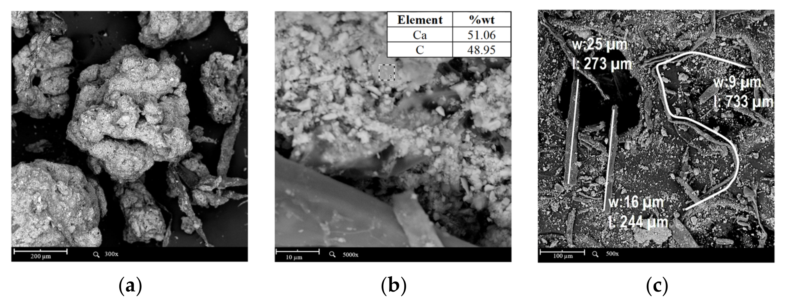
The XRF results show a high content of unburned material (L.O.I.) coming from the calcination of cellulose fibers, which can be observed in Figure 1. SEM-EDS images confirm the presence of CaCO3 and cellulose fibers in the PS. Threads have a width of less than 30 µm and lengths up to 800 µm. The scanning electron microscopy (SEM) analysis was carried out on the PS and composites. The equipment used was a Phenom ProX Desktop (accelerating voltage of 15 kV). The SEM images were complemented with EDX analysis conducted by a Phenom ProSuite v2.8.0 EDS.
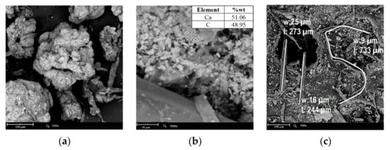
Figure 1.
SEM-EDS images of PS: (a) SEM 300×, (b) EDS, and (c) SEM 500×. Fiber dimensions (w: width, l: length).
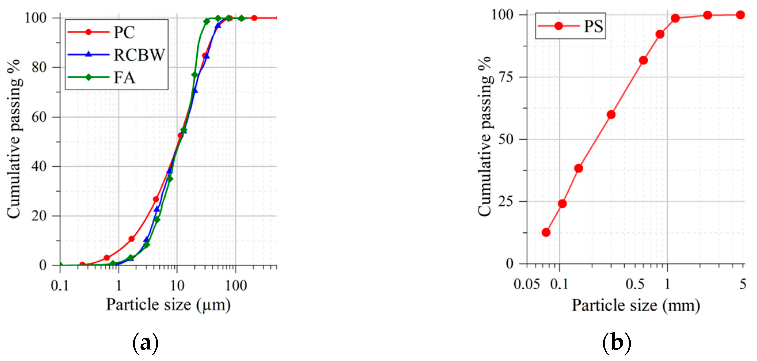
The specific gravity values for pulverized AF and RCBW were 2.19 g/cm3 and 2.69 g/cm3, respectively (ASTM C329 [28]). PS contains hygroscopic cellulose fibers which prevented the measurement of specific gravity; therefore, the value of 0.46 g/cm3 reported corresponds to its bulk density. The average particle size of the materials was measured by laser granulometry using a CILAS Model 1064 Granulometer; the laboratory temperature was 23 °C. The particle size distribution of RCBW, FA, PC and PS materials is shown in Figure 2.

Figure 2.
Granulometry of the considered raw materials: (a) FA, RCBW and PC, and (b) PS.
2.2. Design of AAC Matrices
Using response surface methodology and Minitab 18 statistical software, the RCBW/FA cementitious system mixtures were established. The design factors for this study were the SiO2/Al2O3 and Na2O/SiO2 molar ratios. The molar ratios were obtained after calculating the quantities of silica, alumina, and sodium in each raw material. FA and RCBW provide silica and alumina to the system. On the other hand, sodium silicate contributes to silica and introduces sodium to the system, together with sodium hydroxide.
The liquid/solid ratio (L/s) was kept constant at 0.3 and the addition of PC 10 wt.% by weight of the RCBW/FA mixture was also kept constant. The levels used for each design factor are shown in Table 2.
Table 2.
Design Levels for Response Surface Methodology.
The response variable for this study was the compressive strength of the AAC matrix at 28 days of setting. Considering the future application of the composite (masonry units), the AAC matrix was set to develop 35 MPa as a selection criterion because the incorporation of PS is expected to decrease the compressive strength of the composite.
The linear model or mathematical expression used to process the data was determined by the response surface equation:
where: is the response variable 28-day compression strength (MPa); are the coefficients of the model, with ; is the molar ratio SiO2/Al2O3; is the molar ratio Na2O/SiO2; and are the quadratic effects; is the interaction effect between the molar ratios; and, finally, is the experimental error. ANOVA analysis identified the significant differences between the different treatments carried out.
2.2.1. Conformation of Test Specimens
The AAC matrices were formed by mixing the solid precursors (FA, RCBW and PC) in RCBW/FA/PC ratios: 45/45/10. Separately, the activating alkaline solution composed of NaOH and Na2SiO3 was prepared 2 h before incorporation into the solid precursors. The nomenclature Cx defines the cementitious agents, where x is the number of the mixture given in the experiment.
A total of 17 matrix mixtures was produced. Among these 17 systems, 14 encompass distinct dosages characterized by varying SiO2/Al2O3 ratios (4.3 to 5.2) and Na2O/SiO2 ratios (0.1 to 0.2), while the remaining 3 represent the central point that was replicated to minimize the error of the model. The specimens were cast and molded into cylinders (Φ30 mm × H60 mm) and prisms (40 mm × 40 mm × 160 mm), which after 24 h were demolded and stored in a stretch wrap at room temperature for 28 days.
Matrices with compressive strengths over 35 MPa and an initial setting time of more than 1 h were selected to form the composites. This time was established to guarantee the extrusion of the largest possible volume of the dies and AAC-PS composites and to avoid damage to the machine due to clogging. The setting time was measured with the VICAT method (ASTM C191 [29]), to provide the matrices and composites with the plastic consistency required for their extrusion. The composites were identified through the nomenclature CxPSxx, where Cx identifies the AAC matrix, and PSxx corresponds to the amount of PS incorporated (0, 25, 35, and 45%wt.). Figure 3 schematizes the extrusion molding of the test specimens (cylindrical and prismatic). In order to keep the extrusion speed of the specimens constant, the frequency of the extruder motor was set at 0.3 Hz.
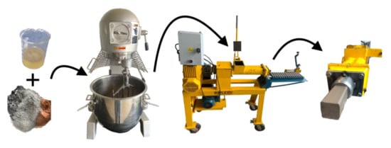
Figure 3.
Diagram of the extruded composites manufacturing process.
Cylindrical specimens (Φ30 mm × H60 mm) and prisms (40 mm × 40 mm × 160 mm) of the matrices and composites were formed by extrusion. After extrusion, the specimens were cut to the required lengths and then stored wrapped in stretch film for 28 days at room temperature. After preliminary tests, it was found that the suitable L/s ratio for extruding the matrices and composites ranged between 0.21 and 0.29. Consequently, a suitable consistency for extrusion of the composites was achieved by controlling the amount of water in the NaOH activator solution.
2.2.2. Mechanical, Physical, and Thermal Characterization
The extruded specimens (Φ30 mm × H60 mm) were tested in compression in a Forney FT-40 universal testing machine after 28 days of curing. The flexural test was performed on specimens of the matrices and composites (40 mm × 40 mm × 160 mm) with 28 days of cure. A three-point bending test with a load head displacement rate of 1.27 mm/min, was conducted using a Humboldt Mfg HM-3000 Series Master Loader test frame (Humboldt Mfg, Decagon Devices Inc., Pullman, WA, USA). Density, water absorption, and porosity were determined following the test method described in ASTM C642-13 [30].
The thermal behavior of the matrices and composites was evaluated by thermal conductivity and flame resistance tests. The thermal conductivity of the specimens (Φ30 mm × H60 mm) was performed on a Decagon Devices Inc. KD2 Pro machine, equipped with a climatic chamber Memmert HPP 110 set at 25 °C and 50%RH. The flame resistance test was carried out according to the procedure mentioned in the study by Vásquez-Molina et al. [31]. The tested specimens consisted of prismatic sections recovered from the flexural strength test. The flame of a propane gas-fueled torch with a constant temperature (900 °C), with its nozzle fixed at 15 cm from the front face of the specimens, was applied for 1 h. The changes in temperature were recorded every 5 min by means of thermocouples attached to the front and rear faces of the specimens. During the direct flame exposure test, physical damage on the exposed surface, cracking, expansion, fracture or melting of the material was evaluated. The temperature difference across the thickness of the specimens (40 mm) was calculated by subtracting the temperatures recorded on the front face (exposed flame) and the back face.
3. Results and Discussion
3.1. Selection of AAC Matrices Used in Composites
3.1.1. Criterion 1: Compressive Strength at 28 Days
Figure 4 shows the contour plot for the compressive strength (28 days) of the matrices, which is a representation of the obtained model (Equation (2)) with an R2 fit of 95.9%.
where is the value of the SiO2/Al2O3 factor, is the value of the Na2O/SiO2 factor, and is the 28-day compressive strength in MPa.
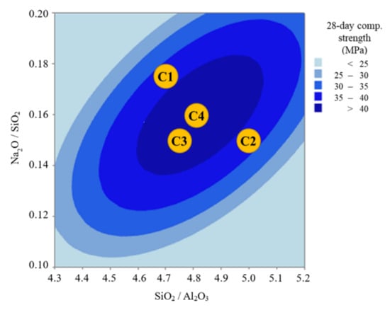
Figure 4.
Contour plot of 28-day compressive strength as a function of factors for AAC matrices (RCBW/FA/PC: 45/45/10).
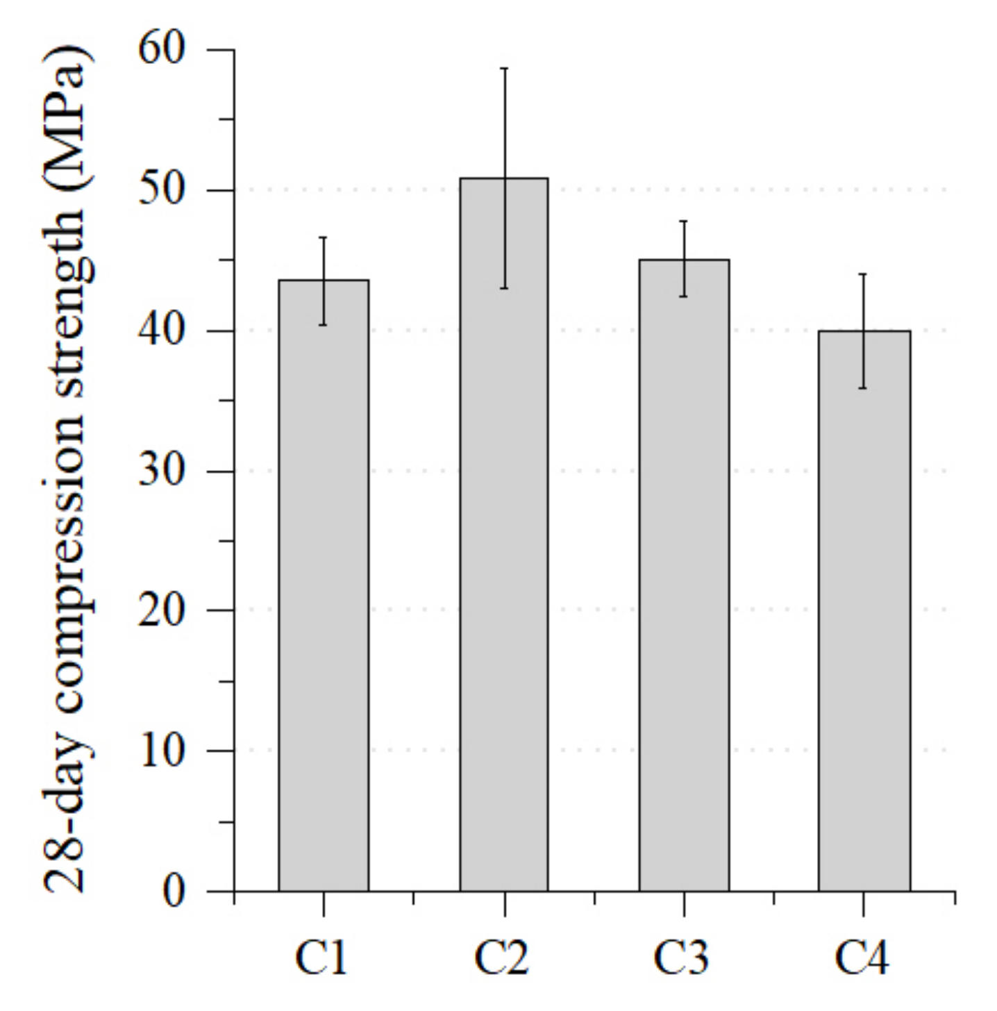
Among the 17 tested matrices, only 4 (C1, C2, C3 and C4) were eligible because their projected compressive strength exceeded 35 MPa, meeting the initial selection criterion. Figure 5 shows the compressive strength values of the mentioned systems.
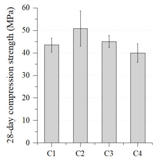
Figure 5.
Compressive strength at 28 days of the selected AAC matrices.
These compressive strengths were obtained with SiO2/Al2O3 and Na2O/ SiO2 ratios of 4.5 to 5.1 and 0.13 to 0.18, respectively. Values below these ranges lead to soluble silica deficiency and lower pH, which will cause a low dissolution of SiO2 and Al2O3. On the other hand, SiO2/ Al2O3 values above 5.1 suggest high Na2SiO3 content, which in the presence of PC accelerates the setting reaction. Consequently, the time required to dissolve all the SiO2 and Al2O3 is reduced. Both situations lead to a low formation of the reaction gels that provide strength and durability to the matrices. The C2 matrix developed the highest strength (51 MPa), while the C4 mixture recorded the minimum required strength (35 MPa). These values coincide with the results of matrices made with RCBW/FA without PC addition [9,10].
Mahmoodi et al. report that the highest strengths were achieved with curing at 75 °C, and that room temperature curing was effective only when high-calcium class C FA was used. In the present study, incorporating PC as a source of calcium promoted the setting and rapid gain in compressive strength of the matrices cured at room temperature.
Table 3 shows the analysis of variance of the model for the AACs evaluated in this study.
Table 3.
Analysis of Variance of the Response Surface Model of the RCBW/FA/PC Matrices.
It can be observed that the sum of the squares of the model (2117.88) is greater than that of the error (62.23). Therefore, the predictors used explain the variation in the model. It can also be observed that the p-value of the lack of fit is 0.45, higher than the significance level (α) of 0.05 stated in the analysis. This suggests that the lack of fit is not statistically significant.
3.1.2. Criterion 2: Setting Time
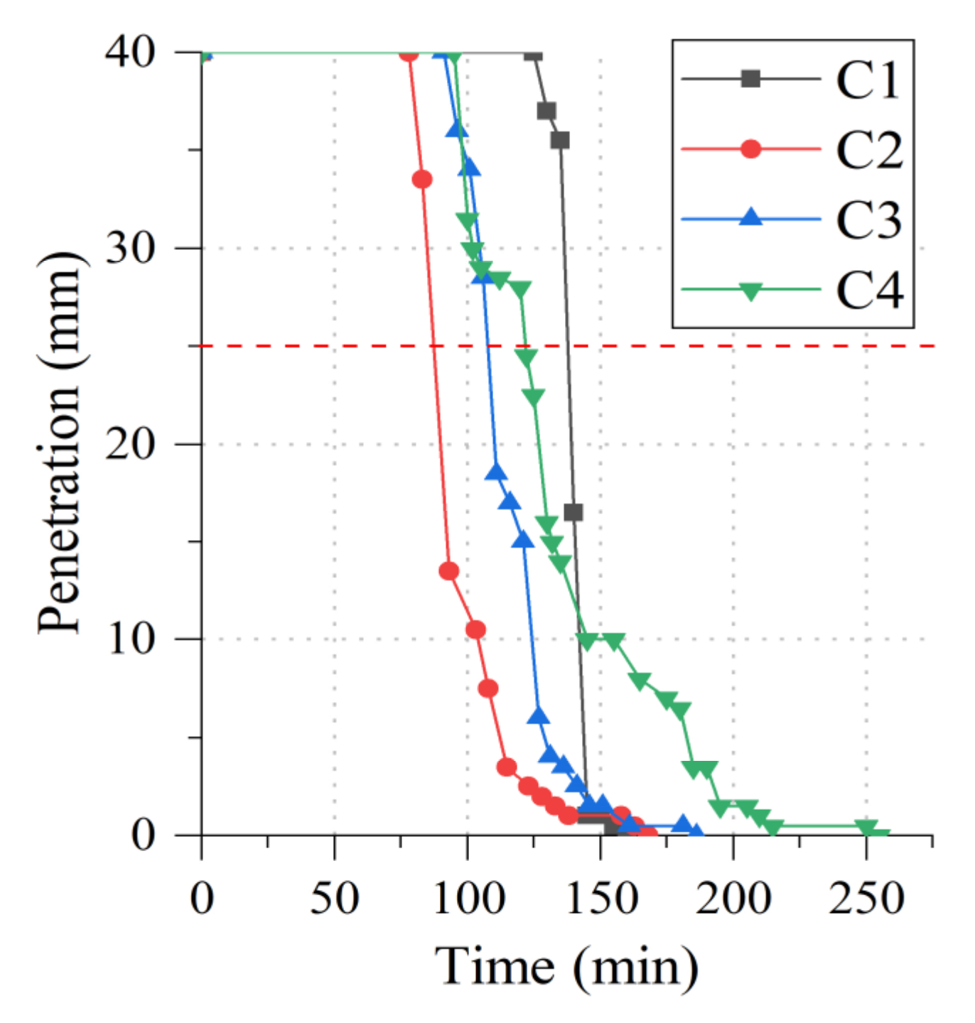
Figure 6 shows the setting time evolution of the C1, C2, C3 and C4 matrices. This property of the fresh state directly influences the maximum time available to extrude the AAC matrices and composites.
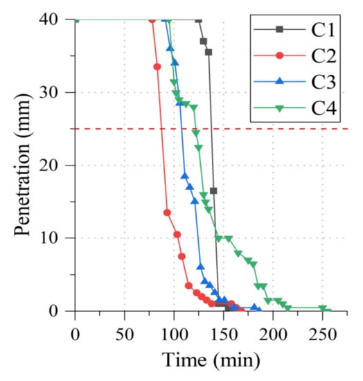
Figure 6.
Setting times of AAC matrices according to Vicat test.
Initial setting times from 87 to 141 min and final setting times from 160 to 255 min were recorded. The literature review revealed that studies on RCBW/FA/PC cementitious systems have not evaluated the setting time. The most similar are related to FA + 10% PC matrices with initial setting times of 80 to 110 min and final setting times of 115 to 145 min (solution/binder = 0.5) [32]. On the other hand, matrices formed using RCBW as the sole precursor developed initial setting times of 20 to 54 min and final setting times of 50 to 275 min (liquid/solid = 0.3) [8]. In both studies, it was mentioned that the composition of the activating solution has a significant effect on the reaction kinetics of the cementitious agents, which affects the setting and hardening time [8]. It has been reported that setting times are halved when the incorporated PC is increased from 5 to 15%wt. (solution/cement = 0.6) [22].
In this study, it was observed that cementitious materials with SiO2/Al2O3 < 4.7 and Na2O/SiO2 > 0.20 harden rapidly. This behavior may be due to the increased concentration of OH- ions from the SH in the activating solution. This favors the dissolution of SiO2 and Al2O3 (contained in FA and RCBW) and accelerates the formation of reaction gels that decrease the workability of the matrices in the fresh state.
From these results (Figure 6), matrices C1 and C4 were selected as they exhibited the longest setting times. The setting time ranges for the C1 and C4 matrices were 141–160 min and 122–255 min, respectively.
3.2. Characterization of Extruded Composites
3.2.1. Fresh State Performance of AAC-PS Composites
During the extrusion tests, the direct dependence of matrix plasticity on the L/s ratio and the concentration of the activating solution was observed. It was found that high Na2SiO3 content increased the viscosity of the AAC cementitious agent at the beginning of the setting. However, it rapidly accelerates the setting, which reduces the plasticity of the cementitious material and makes extrusion difficult. For this reason, it was critical to control the amount of Na2SiO3 in the activator solution.
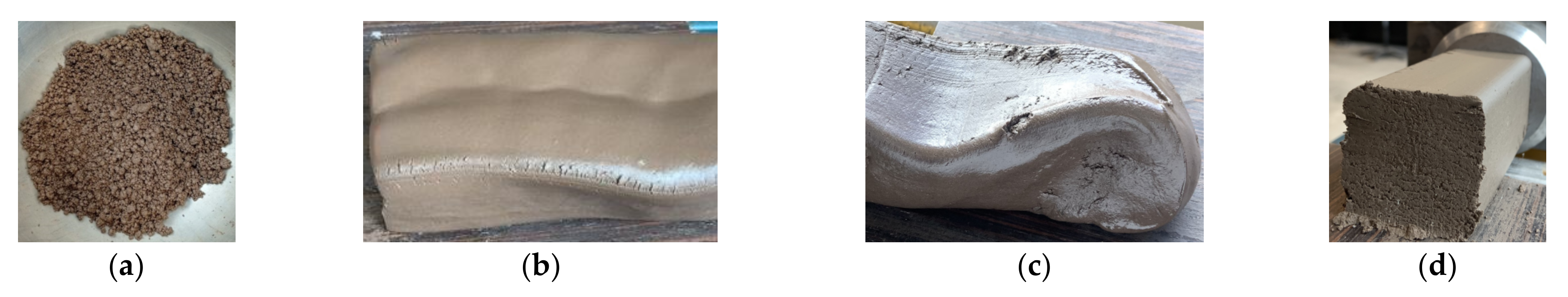
The shades and composites exhibited a lumpy but plastic texture associated with their low L/s ratio. Figure 7 contrasts the deformation of the extruded dies with the dimensional stability of the C1PS25 composite.

Figure 7.
Consistencies of: (a) mixtures before extrusion and extruded (b) C1, (c) C4 and (d) C1PS25.
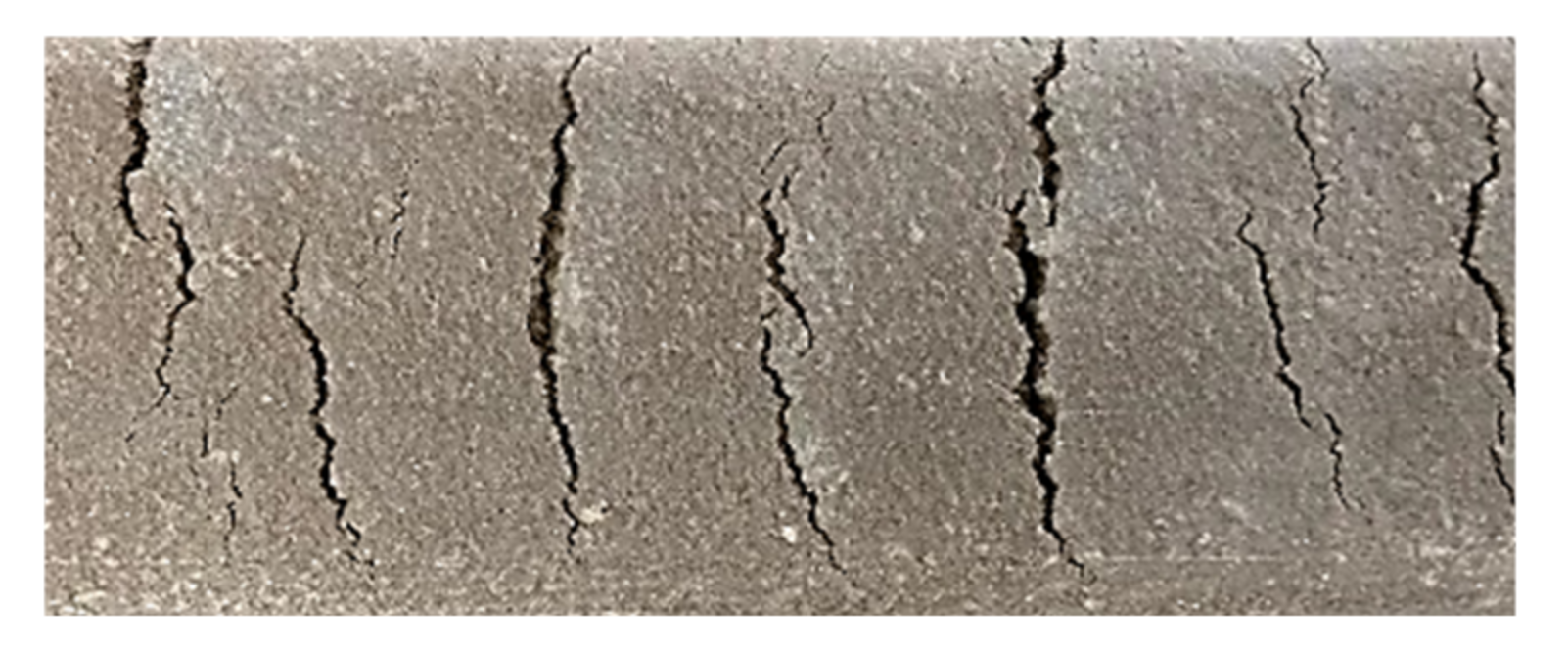
Composites made of C1 and C4 matrices and the same amount of PS exhibited very similar flowability. However, the higher SiO2/ Al2O3 ratio of the C4 matrix slightly reduced the extrudability of the composites, due to factors previously discussed. Increasing the PS from 25 to 45% decreased the deformation of the matrices, due to the increased friction of the cellulose fibers with the matrix. In addition, due to their hygroscopic nature, the fibers absorb moisture from the cementitious material, decreasing its flowability. A similar study found that the addition of 10%wt. of PS to a cementitious material reduced its flowability from 112 to 75%. This study considered the flowability (ASTM C 1437-20 [33]) as the increase in diameter at the base of the mortar with respect to its original value [23]. It was observed that PS additions higher than 45%, particularly in matrices with short setting times, further hindered the extrusion of the composites. Figure 8 shows surface cracks generated in a composite extruded under such conditions due to increased friction with the extrusion die. Cracks can also originate from low cohesion, local water drainage, low early tensile strength and deformation by fibers located on the surface [34,35].
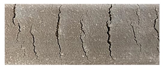
Figure 8.
Surface cracks formed during extrusion of composites with PS > 45%wt.
The twin screws of the extruder helped disperse the PS fibers in the matrices with a low L/s ratio. Therefore, extrusion strengthens the fiber–matrix interfacial transition zone (ITZ) to a greater extent than processes such as casting or compacting [34]. Additionally, the pressure applied by the extruder distributes and orients the fibers in the direction of the material flow, increasing their cohesion with the matrix.
3.2.2. Compressive and Flexural Strength of Extruded Composites
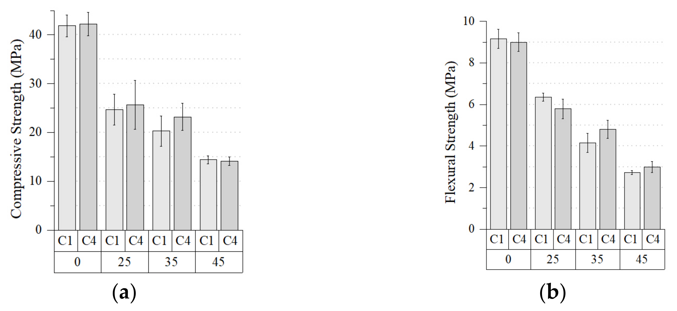
At 28 days of age, the compressive strength of the extruded composites ranged from 14 to 25 MPa (Figure 9). Decreasing compressive strength was observed with increasing PS. In C1PS25, C1PS35 and C1PS45, the strength drops were 13, 28 and 49%, respectively. In C4PS25, C4PS35 and C4PS45, the strength drops were 29, 36 and 61%, respectively. The compressive strength of AACs matrices (cementitious ceramics) exceeds that of PS (a cellulosic polymer), which explains the drops in the composite’s strength. It has been reported that the addition of 10%wt. of PS decreased the compressive strength of a cementitious matrix by 48% [23].
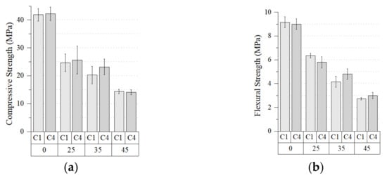
Figure 9.
Strength of extruded composites: (a) compression and (b) flexural.
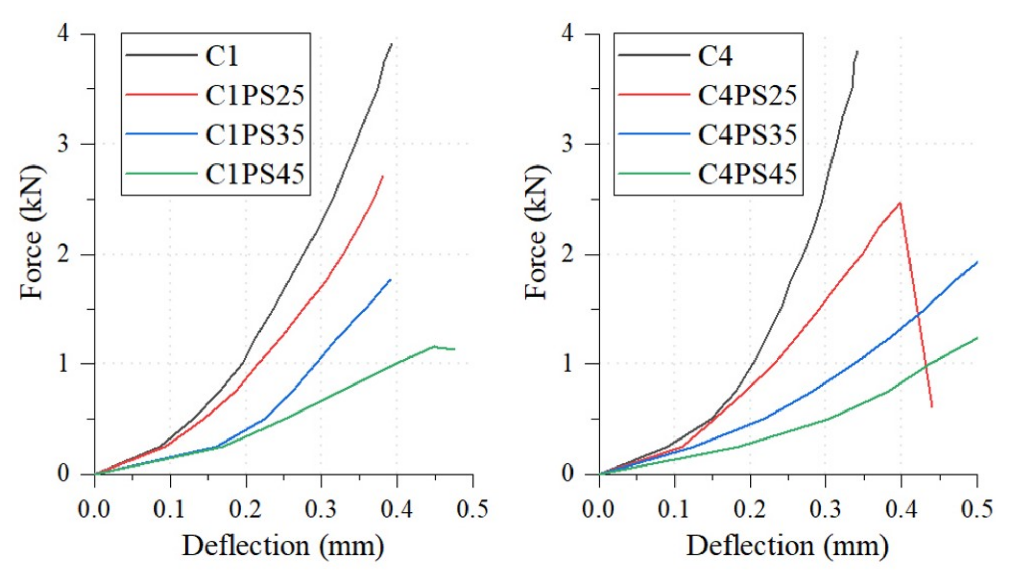
The flexural behavior of the composites (Figure 9) follows a similar trend to that observed for the compressive strength. The incorporation of PS in the system resulted in a decrease of the modulus of rupture (MOF). The reduction for C1PS25, C1PS35 and C1PS45 was 31, 55 and 70%; while for C4PS25, C4PS35 and C4PS45 it was 36, 47 and 67%. Figure 10 shows the load–deflection curves for the composites. Despite the decrease in flexural strength, an increase in deflection of up to 60% and a less abrupt drop in applied load can be observed. The increase in the modulus of rupture is also observed in cementitious matrices as a consequence of the incorporation of bamboo (12%wt.) and rice straw (8%wt.) fibers [36].
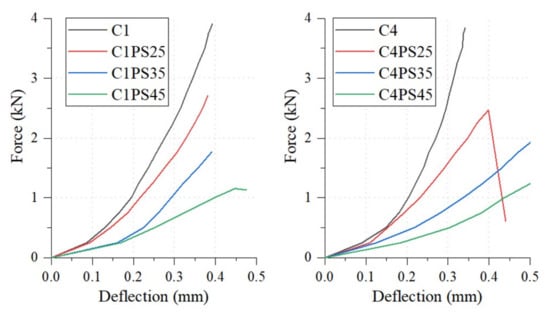
Figure 10.
Load–deflection curves of matrices and composites.
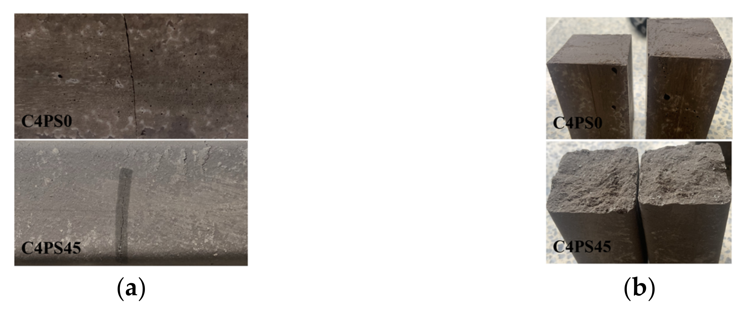
Figure 11 shows the fracture surface of specimens C4 and C4PS45 subjected to the bending test. The C4 matrix exhibited a sub-smooth and brittle fracture with a smooth and flat failure surface. In contrast, the irregular fracture of C4PS45 suggests that the PS fibers blocked crack propagation and increased the toughness of the composites. Increased toughness of cementitious shades due to the incorporation of bamboo and rice straw fibers has been reported [36]. However, this impact does not extend to increased flexural strength, due to the size and cellulosic nature of the PS fibers.
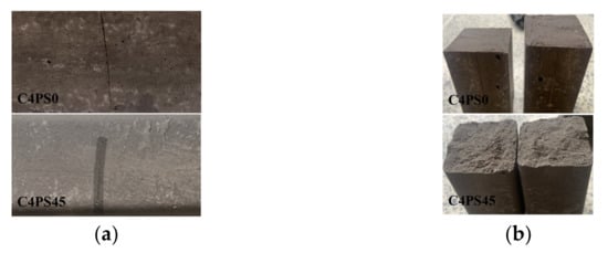
Figure 11.
Flexural failure of composites: (a) crack and (b) failure surfaces.
Overall, both the compressive and flexural strength of the cementitious composites decreased as the amount of PS incorporated increased, which is consistent with reports from other studies [37,38,39]. Additionally, higher PS incorporation into the composite means that fewer of the reaction gels that stiffen the matrix and give it strength will be formed. C1PS25 and C4PS25 developed strengths close to 25 MPa, with C1PS25 having the highest flexural strength (MR > 6 MPa). The SEM images (Figure 12) show the pulverized PS and its fibers embedded in the matrices. CaCO3 deposits are observed on the PS fibers, identified as CaO in the XRF analysis (Table 1). This same morphology was observed in the composites with 25 and 35% PS.
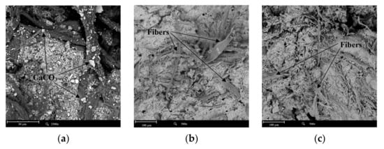
Figure 12.
SEM images of (a) PS at 2500×, and composites (b) C1PS45 and (c) C4PS45 at 500×.
3.2.3. Density, Water Absorption and Porosity of Extruded Composites
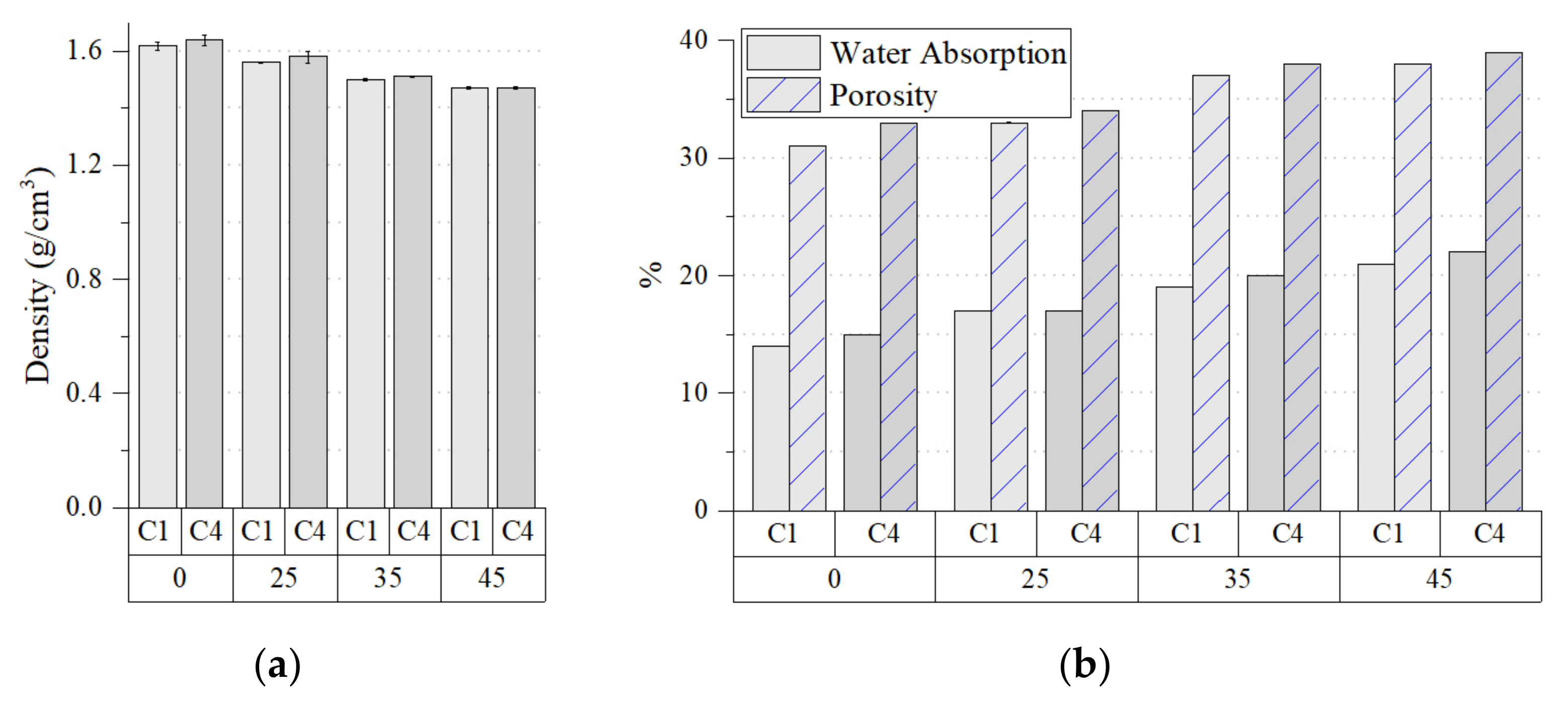
Figure 13 compares the variations in density, water absorption and porosity of the composites.
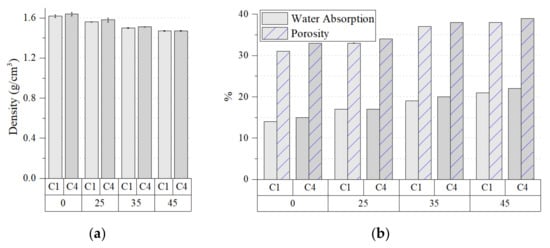
Figure 13.
(a) Density, and (b) water absorption and porosity of extruded matrices and composites.
It can be observed that the density of the composites decreased as the PS increased, because the density of PS (0.46 g/cm3) is lower than that of both matrices. The density of C1PS25 and C4PS25 decreased by 4%, while that of C1PS45 and C4PS45 decreased by 9 and 10%, respectively; this property varies depending on the nature, size, and morphology of the incorporated cellulose fibers [26,37,38,40]. The addition of 16%wt. of bamboo fibers to cementitious matrices decreased their density by 87.6% but increased their water absorption (twice) and porosity (1.4 times) [40]. It has been reported that the addition of 10%wt. of PS reduced the density of geopolymer matrices by 9% [23]. Incorporating PS in calcium sulfoaluminate cement allowed the rheology required for 3D printing to be controlled. However, the increase in the PS gradually increased the porosity of the composite [37]. In this study, C4PS25 exhibited the highest density (1.56 g/cm3), while C1PS45 exhibited the lowest (1.47 g/cm3). All composites exhibited densities below 1.68 g/cm3, which qualifies them to manufacture lightweight masonry units (ASTM Committee C15). Currently, commercial lightweight masonry is manufactured with foamed concrete or concrete incorporating expanded aggregates such as EPS [41,42], expanded perlite [43], pumice [44,45], clays [44]; or porous aggregates such as cork [46,47]. Lightweight masonry reduces the dead load in buildings, reducing the dimensions of structural elements such as columns, beams, walls, and foundations.
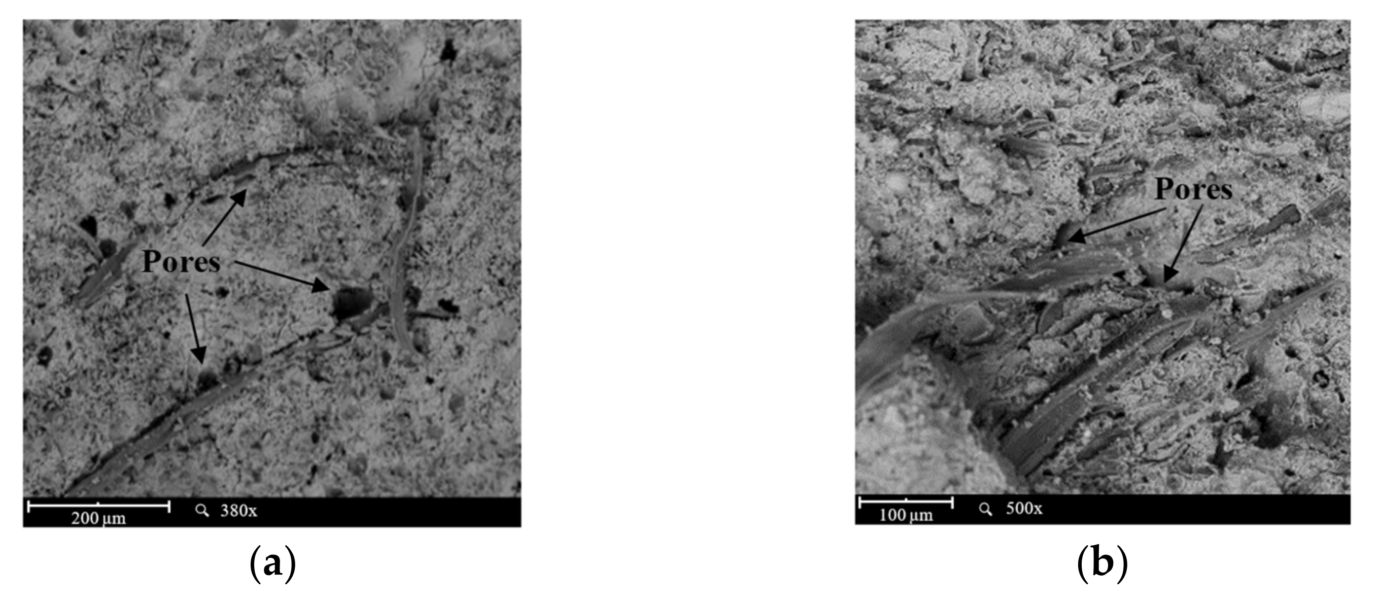
In the processed composites C1 and C4, the increase in incorporated PS increased both water absorption and porosity (Figure 14b). The incorporation of PS between 25 and 45%wt. increased porosity by 3 to 23% and water absorption by 13 to 50% in the composites. The increase in water absorption is due to the increase in the amount of PS (hydrophilic) and the increase in porosity. The SEM images (Figure 14) show pores formed in the fiber–matrix interfacial transition zone (ITZ). These pores arise because the PS (hydrophilic cellulose) fibers initially swell when they absorb moisture from the fresh AAC matrices. As the setting progresses, the matrices harden and contract, pressing the fibers together. At the end of the setting, the heat from the hydration causes the water stored in the fibers to evaporate gradually. Consequently, the dehydrated fibers shrink and detach from the matrix, generating pores around them [48,49].

Figure 14.
SEM images of composites: (a) C1PS25 and (b) C5PS35.
The formation of a porous ITZ decreases the strength and increases the moisture absorption of the composites. These adverse effects can be counteracted by pre-treatment in alkaline solutions, which removes impurities from the fibers and increases their surface roughness and compatibility with the cementitious matrix [50]. It has been reported that the incorporation of 10%wt. of PS into geopolymer matrices increased water absorption by up to 9% and porosity by up to 16.7% [23].
Water absorption was 17% for C1PS25 and C4PS25, 19 and 20% for C1PS35 and C4PS35, and 21 and 22% for C1PS45 and C4PS45. All composites developed compressive strengths above 13 MPa, qualifying them for masonry unit manufacture (Table 4).
Table 4.
Water absorption (WA) and compressive strength (f’c) requirements for lightweight masonry units per ASTM standard.
Only C1PS25 and C4PS25 are suitable for fabricating structural masonry units, which compete in performance with their concrete counterparts (ASTM C90 and ASTM C1790). Composites with 35% and 45% PS that recorded water absorption greater than 17% are unsuitable for masonry units. Applying a water repellent (which decreases water absorption by up to 17%), C1PS35 and C4PS35 could be used to form bricks with a compressive strength higher than 17.2 MPa (ASTM C55). The same procedure would allow concrete to be substituted for C1PS45 and C4PS45 to make structural masonry units (ASTM C90). The incorporation, in mass or surface, of hydrophobic admixtures [55,56,57] into the composite and fiber pre-treatments is effective in reducing water absorption. Chemical or physical treatments modify the surface of the fibers, improving their durability, mechanical properties and adhesion to the matrix [58,59,60,61,62]. Coating cellulose fibers with silica nanoparticles reduces water absorption by up to 50% [58]. The addition of PS ash reduces water absorption in concrete by up to 80% without appreciable detriment to its density and mechanical strength [55], which would be beneficial for the composites presented in this article.
3.2.4. Thermal Conductivity and Flame Resistance of the Composites
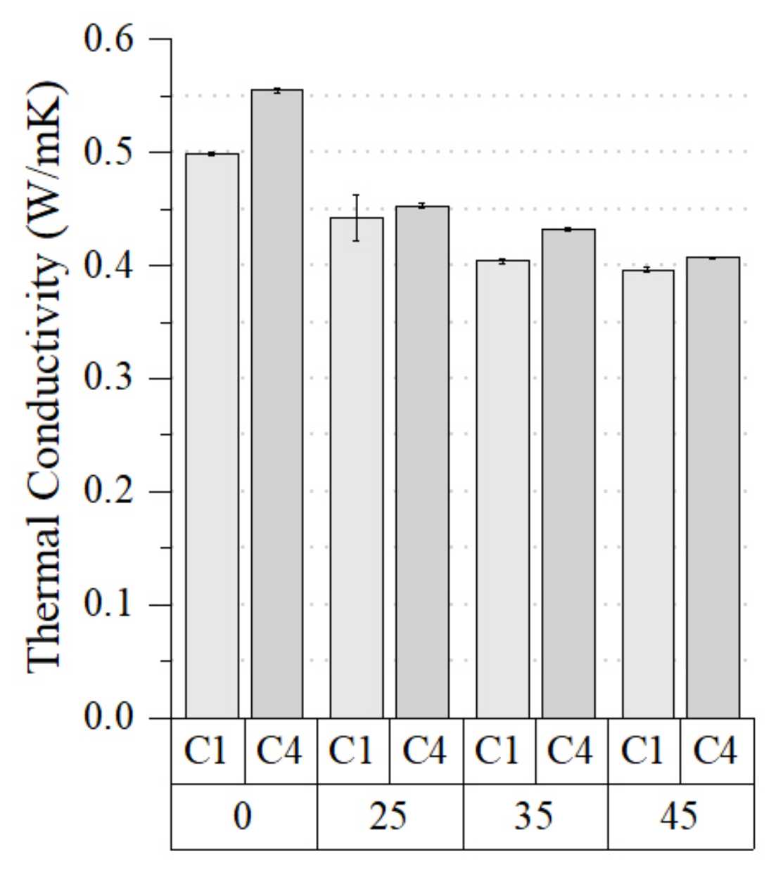
Figure 15 shows the results of the thermal conductivity tests of the developed composites.
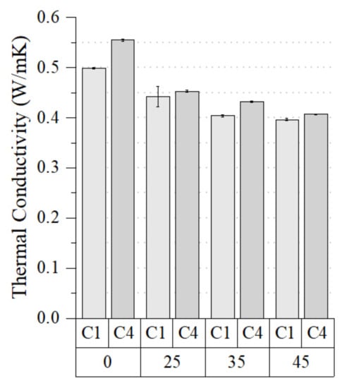
Figure 15.
Thermal conductivity of the blends with different PS addition.
It can be observed that the thermal conductivity of the composites decreased with the increase in PS. C1PS45 (0.396 W/mK) and C4PS45 (0.407 W/mK) exhibited the lowest thermal conductivity values. Slightly more thermally conductive were C1PS35 (0.404 W/mK), C4PS35 (0.432 W/mK), C1PS25 (0.442 W/mK) and C4PS25 (0.453 W/mK). The thermal conductivities of C1 (0.499 W/mK) and C4 (0.555 W/mK) matrices were very similar to those reported for highly activated coal ash cements (0.46–0.87 W/mK) [63]. The denser C4 matrix (Figure 14) conducts more heat than the C1 matrix, which is also reflected in its composites. The matrices are denser the higher the volume of reaction gels formed, which is related to the SiO2/ Al2O3 ratio, which in C4 (4.8) was higher than in C1 (4.7). The thermal conductivity of the composites is also affected by the porosity and thermal conductivity of the PS cellulosic fibers. The thermal conductivity of PS is 0.07 W/mK but increases to 0.12 W/mK when compacted by compression and can vary with fiber size [26]. Comparatively, the thermal conductivity of traditional concrete made with PC and stone aggregates ranges between 1.03 and 3.82 W/mK [64]. Consequently, AAC-PS composites would provide better insulation and thermal comfort in buildings.
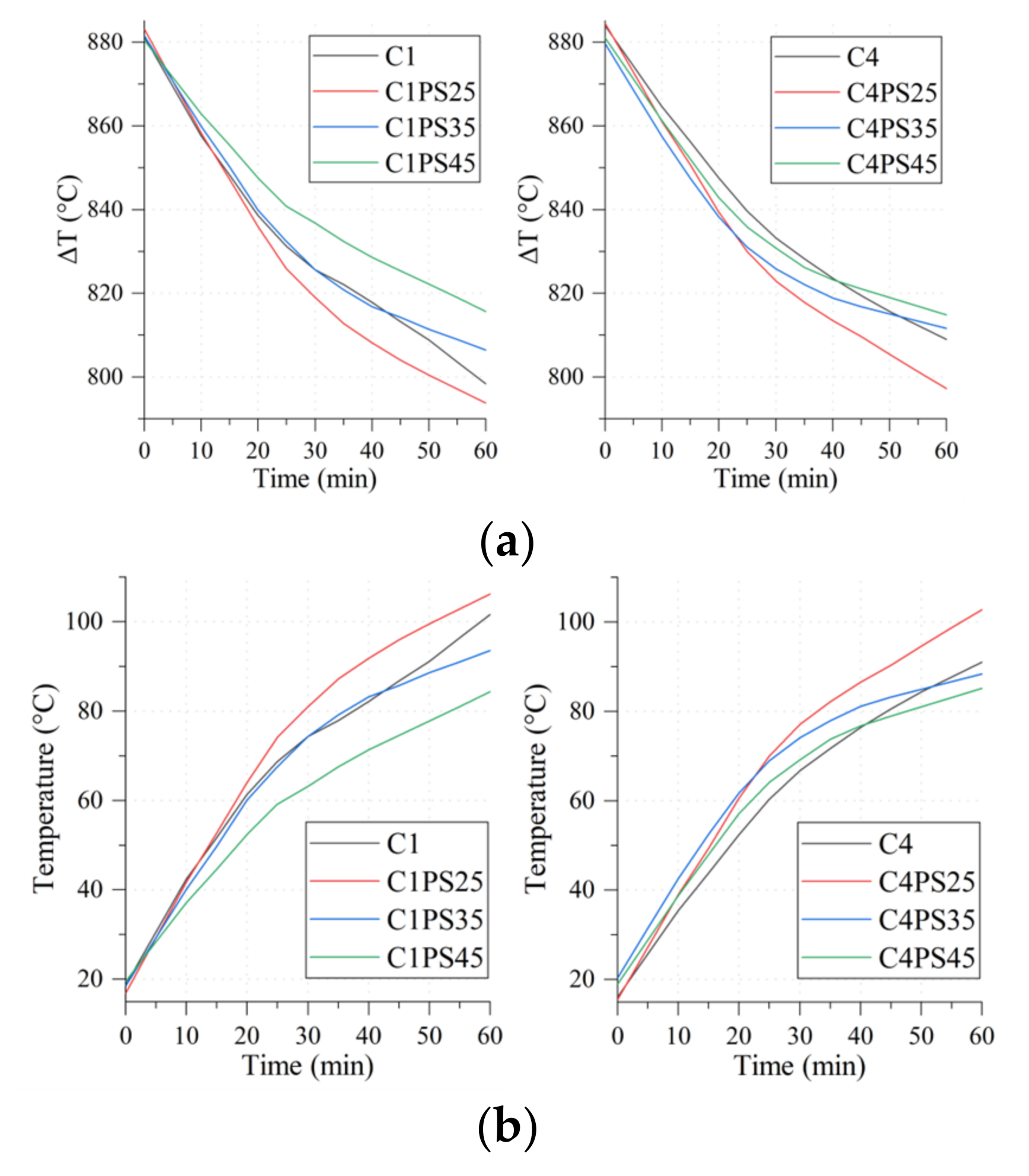
Figure 16 shows the thermal evolution of the matrices and their composites during 1 h of direct flame exposure.
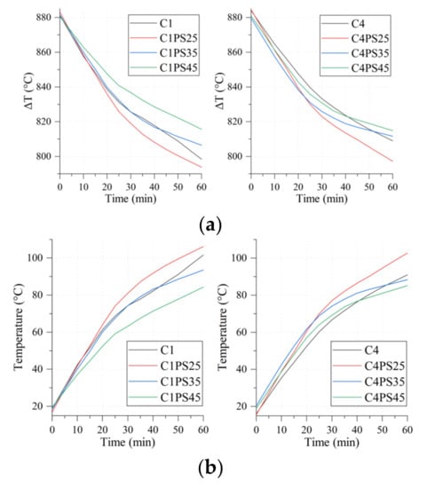
Figure 16.
Thermal evolution of specimens exposed to flame: (a) temperature on the cold face and (b) temperature delta between the faces.
Figure 16a shows that the temperature recorded on the opposite side of the flame decreased with the increase in PS in the composites. This result is congruent with the decrease in thermal conductivity of the composites (Figure 15) and is associated with the thermal insulation provided by the cellulosic fibers of the PS. Figure 16b shows the thermal delta change between the specimens’ faces over the test time. The decrease in the thermal delta is verified with the increase in PS fibers, which blocked the heat flow through the thickness of the composites.
The C1 and C4 matrices deviate from this behavior; their opposite faces should reach higher temperatures than their composites, as they conduct heat better (Figure 15). A plausible reason for this is that pre-existing cracks in both matrices blocked the heat flow. This would have occurred because the specimens for this test were segments of the failed flexural specimens. In composites, PS fibers restrict crack propagation; therefore, heat flow would be controlled by the thermal conductivity of PS.
It is shown that after 1 h of direct flame, the temperature delta between the face exposed to direct flame and the opposite face is between 800 and 820 °C. In another study [31], the same test was performed on a sample with a smaller thicknes; therefore, the difference observed after 30 min was approximately 500 °C, which, although more minor, is similar to the behavior in this study.
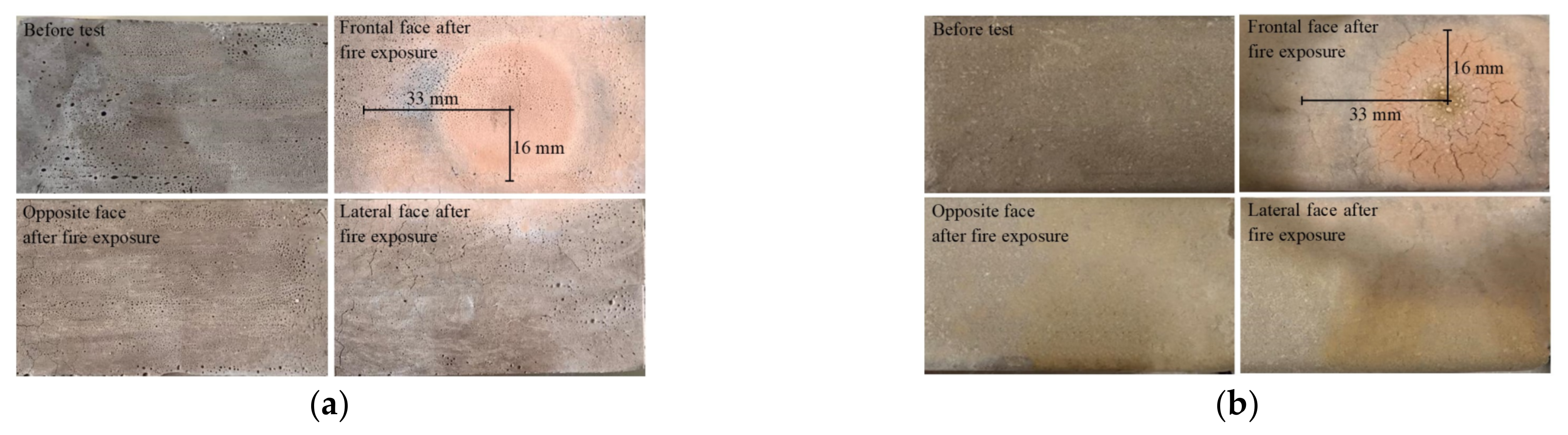
Figure 17 shows the appearance of specimens C4 and C4PS45 before and after exposure to a direct flame.
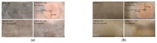
Figure 17.
Appearance of flame-exposed specimens: (a) C4 and (b) C4PS45.
On the front face of all specimens, a circular heat-affected zone (HAZ) was observed, formed by radial heat diffusion. The central region of the HAZ turned red, very similar to that exhibited by the brick used as a cementitious precursor, a phenomenon induced by the transformation into hematite (α-Fe2O3) at 690 °C [65] of iron oxides and hydroxides contained in the solid precursors (FA and RCBW). In contrast to the C4 matrix, a black ring is formed in the HAZ C4PS45, which surrounds the central region and is also seen as a parabola rim on the side face. This suggests that, in the central area, the flame completely calcines the cellulose fibers, but at 16 mm from the center, the lower temperature only succeeds in charring the fibers. Beyond the 33 mm that the HAZ extended, heat diffusion was insufficient to affect the morphology of the specimens. In the central region of the HAZ of C4PS45, a radial pattern of surface cracks formed, which is absent in the C4 matrix, which only exhibits some transverse cracks. These cracks were possibly caused by thermal stresses induced by high transient temperature gradients, also known as thermal shock. The damage generated could range from a diffuse network of microcracks to localized macrocracks, depending on the thermal shock cycles and the size of the material’s crystals [66].
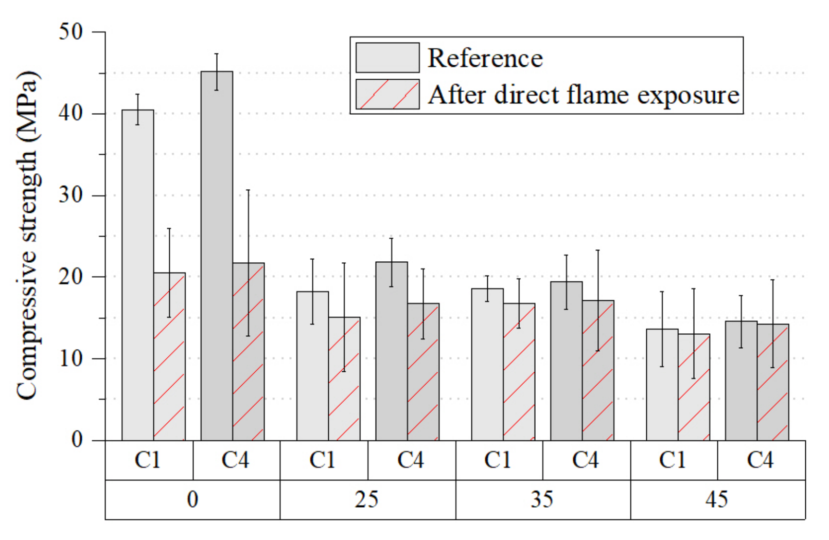
Apart from surface cracking, the flame-exposed specimens retained their structural and dimensional integrity. Figure 18 shows the change in compressive strength of the matrices and their composites induced by their exposure to the flame for 1 h.
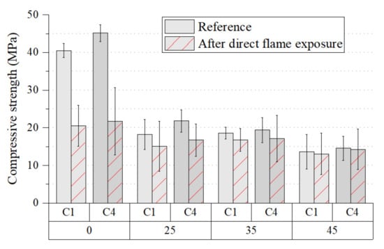
Figure 18.
Compressive strength of matrices and composites exposed to flame.
It can be observed that flame exposure decreased the strength of both matrices C1 (49%) and C4 (52%), and their composites C1PS25 (17%), C4PS25 (23%), C1PS35 (10%), C4PS35 (12%), C1PS45 (4%), and C4PS45 (2%). With a higher percentage of PS there is a lower drop in strength. This behavior reaffirms the hypothesis that PS fibers block the crack propagation and heat flow. Consequently, the increase in fibers reduces the thermal degradation of matrix-forming reaction gels. This hypothesis could be further corroborated by the higher strength variations in C4 and its composites, which were made with a higher SiO2/Al2O3 ratio than that used in C1 and its composites.
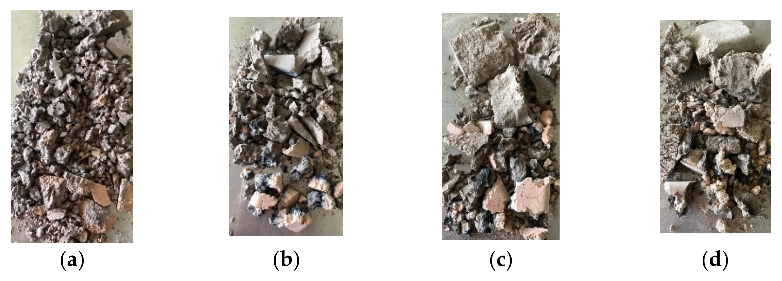
Figure 19 shows the compressive failure fragments of the specimens exposed to the flame.
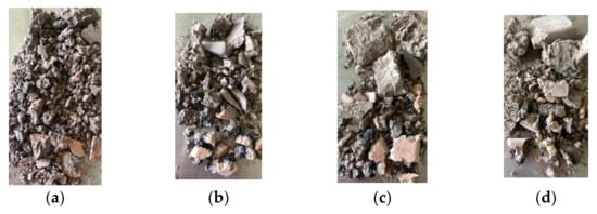
Figure 19.
Fragments of the compressive failure of flame-exposed specimens: (a) C4PS0, (b) C4PS25, (c) C4PS35 and (d) C4PS45.
It can be observed that the higher the PS content in the composite is, the larger the fragments are. This shows that cellulose fibers provide toughness to cementitious matrices, blocking the propagation of cracks by shrinkage and load application [67]. In all specimens, fracture by compressive loading was initiated in the area exposed to the flame. This is related to the calcination and carbonization of the PS fiber and localized volumetric changes that generate cracks.
C1PS45 and C4PS45 composites have high potential for use in the manufacture of fire-resistant building materials. They can be implemented in Category I buildings according to Title J of NSR-10 (the Colombian earthquake building code) where potential fire hazards exist. In this regard, prefabricated elements and geopolymer cement would help to protect buildings in the case of fire [31].
4. Conclusions
Alkali-activated cementitious binders (AACs) and their composites (AAC-PS) with paper sludge (PS) were formed by an extrusion process. The AAC matrices, made by alkali-activating red clay brick waste (RCBW), fly ash (FA) and 10% Portland cement (PC), achieved compressive strengths above 35 MPa and offer a sustainable alternative to conventional concretes.
The structural and dimensional stability of the extruded composites was favored by the delayed setting time of the AACs and the incorporation of PS fibers. Due to its plasticizing effect, long setting times were achieved with a Na2O/SiO2 ratio < 0.20 and by controlling the amount of Na2SiO3 in the activating solution. The incorporation of between 25 and 35%wt. of PS increased the viscosity and consistency of the AACs, reducing their deformation after extrusion. When PS incorporation exceeds 45%wt., it leads to surface cracking of the matrices, in particular for AACs with short setting times. This can be solved by using vacuum extruders or wetting the PS before incorporating it into the mix.
In a hardened state, the incremental addition of PS reduced the compressive strength and density of the composites, but their water absorption and porosity increased. These behaviors are explained both by the lower strengths and densities of the PS fibers and by the increased porosity in the interfacial transition zone (ITZ).
All composites exceeded 13 MPa compressive strength, which qualifies them for the manufacture of structural masonry units (ASTM C90 and ASTM C1790). Composites C1PS45 (1.47 g/cm3) and C4PS25 (1.56 g/cm3), whose water absorption was 17%, can be used to manufacture lightweight masonry units (ASTM committee C15). The high-water absorption of C1PS35 (19%), C4PS35 (20%), C1PS45 (21%) and C4PS45 (22%) limits their use in the manufacture of masonry units. However, the application of a water repellent is a possible solution to allow their use in the manufacture of structural masonry units (ASTM C55 and ASTM C90).
The incremental addition of PS also resulted in reduced thermal conductivity and less deterioration of compressive strength due to exposure to a direct flame. In this regard, masonry units manufactured with these AAC-PS composites would improve the structural integrity of fire-exposed buildings. Additionally, the incremental addition of PS improved the flexural performance and toughness which, together with the reduction in density, allows the construction of safer buildings.
Author Contributions
Conceptualization, J.W.R.M. and M.F.V.G.; Funding acquisition, J.W.R.M. and M.F.V.G.; Investigation, A.M.O.S. and A.V.I.; Methodology, J.M.M.A.; Project administration, J.M.M.A.; Resources, J.W.R.M. and J.M.M.A.; Supervision, J.W.R.M., J.M.M.A. and M.F.V.G.; Writing—original draft, A.M.O.S. and A.V.I.; Writing—review and editing, A.M.O.S., A.V.I., J.W.R.M., J.M.M.A. and M.F.V.G. All authors have read and agreed to the published version of the manuscript.
Funding
This research was funded by the Colombian Ministry of Science, Technology, and Innovation (Minciencias) (852 Convocatoria Conectando Conocimiento 2019), project: “Development and evaluation of a cementitious matrix composite material for extrusion molding, based on industrial and urban waste with CO2 mineralization capacity in the structure”, code: 1333-852-72472, Contract 506-2020.
Data Availability Statement
The data presented in this study are available on request from the corresponding author. The data are not publicly available due to the protection of intellectual property.
Acknowledgments
The authors express their gratitude to the Universidad EIA and Minciencias for their support in carrying out this work.
Conflicts of Interest
The authors declare no conflict of interest. The funders had no role in the design of the study; in the collection, analyses, or interpretation of data; in the writing of the manuscript; or in the decision to publish the results.
References
- Zhang, J.; Tan, H.; Bao, M.; Liu, X.; Luo, Z.; Wang, P. Low carbon cementitious materials: Sodium sulfate activated ultra-fine slag/fly ash blends at ambient temperature. J. Clean. Prod. 2021, 280, 124363. [Google Scholar] [CrossRef]
- Alhawat, M.; Ashour, A.; Yildirim, G.; Aldemir, A.; Sahmaran, M. Properties of geopolymers sourced from construction and demolition waste: A review. J. Build. Eng. 2022, 50, 104104. [Google Scholar] [CrossRef]
- García-Lodeiro, I.; Fernández-Jiménez, A.; Palomo, A. Cementos híbridos de bajo impacto ambiental: Reducción del factor clinker. Rev. ALCONPAT 2015, 5, 1–17. [Google Scholar] [CrossRef]
- Provis, J.L.; Bernal, S.A. Geopolymers and Related Alkali-Activated Materials. Annu. Rev. Mater. Res. 2014, 44, 299–327. [Google Scholar] [CrossRef]
- Li, N.; Shi, C.; Zhang, Z.; Wang, H.; Liu, Y. A review on mixture design methods for geopolymer concrete. Compos. Part B Eng. 2019, 178, 107490. [Google Scholar] [CrossRef]
- Robayo-Salazar, R.; Valencia-Saavedra, W.; de Gutiérrez, R.M. Recycling of concrete, ceramic, and masonry waste via alkaline activation: Obtaining and characterization of hybrid cements. J. Build. Eng. 2022, 46, 103698. [Google Scholar] [CrossRef]
- Robayo-Salazar, R.A.; Valencia-Saavedra, W.; de Gutiérrez, R.M. Construction and Demolition Waste (CDW) Recycling—As Both Binder and Aggregates—In Alkali-Activated Materials: A Novel Re-Use Concept. Sustainability 2020, 12, 5775. [Google Scholar] [CrossRef]
- Mahmoodi, O.; Siad, H.; Lachemi, M.; Sahmaran, M. Synthesis and optimization of binary systems of brick and concrete wastes geopolymers at ambient environment. Constr. Build. Mater. 2021, 276, 122217. [Google Scholar] [CrossRef]
- Mahmoodi, O.; Siad, H.; Lachemi, M.; Dadsetan, S.; Sahmaran, M. Optimization of brick waste-based geopolymer binders at ambient temperature and pre-targeted chemical parameters. J. Clean. Prod. 2020, 268, 122285. [Google Scholar] [CrossRef]
- Rovnaník, P.; Řezník, B.; Rovnaníková, P. Blended Alkali-activated Fly Ash/Brick Powder Materials. Procedia Eng. 2016, 151, 108–113. [Google Scholar] [CrossRef]
- Yunsheng, Z.; Wei, S.; Zongjin, L. Impact behavior and microstructural characteristics of PVA fiber reinforced fly ash-geopolymer boards prepared by extrusion technique. J. Mater. Sci. 2006, 41, 2787–2794. [Google Scholar] [CrossRef]
- Yunsheng, Z.; Wei, S.; Zongjin, L.; Xiangming, Z.; Eddie; Chungkong, C. Impact properties of geopolymer based extrudates incorporated with fly ash and PVA short fiber. Constr. Build. Mater. 2008, 22, 370–383. [Google Scholar] [CrossRef]
- Thakur, A.K.; Pappu, A.; Thakur, V.K. Synthesis and characterization of new class of geopolymer hybrid composite materials from industrial wastes. J. Clean. Prod. 2019, 230, 11–20. [Google Scholar] [CrossRef]
- Okada, K.; Imase, A.; Isobe, T.; Nakajima, A. Capillary rise properties of porous geopolymers prepared by an extrusion method using polylactic acid (PLA) fibers as the pore formers. J. Eur. Ceram. Soc. 2011, 31, 461–467. [Google Scholar] [CrossRef]
- Rasouli, H.; Golestani-Fard, F.; Mirhabibi, A.; Nasab, G.; Mackenzie, K.; Shahraki, M. Fabrication and properties of microporous metakaolin-based geopolymer bodies with polylactic acid (PLA) fibers as pore generators. Ceram. Int. 2015, 41, 7872–7880. [Google Scholar] [CrossRef]
- Senthamilselvi, P.; Palanisamy, T.; Senthilkumar, S. Effect of Chloride on Accelerated Corrosion of Steel Rebar in Alkali-Activated Fly Ash and Paper Sludge Ash–Reinforced Concrete. Int. J. Electrochem. Sci. 2022, 17, 221298. [Google Scholar] [CrossRef]
- Senthamilselvi, P.; Palanisamy, T. Experimental and analytical study on flexural behaviour of fly ash and paper sludge ash based geopolymer concrete. Comput. Concr. 2018, 21, 157–166. [Google Scholar] [CrossRef]
- Santa, R.A.A.B.; Bernardin, A.M.; Riella, H.G.; Kuhnen, N.C. Geopolymer synthetized from bottom coal ash and calcined paper sludge. J. Clean. Prod. 2013, 57, 302–307. [Google Scholar] [CrossRef]
- Moukannaa, S.; Kursula, K.; Perumal, P.; Ohenoja, K.; Illikainen, M. Recycling of Precast Concrete Waste Sludge with Paper Mill and Biomass Ashes for Lightweight Granulated Aggregate Production. Front. Mater. 2022, 9, 877160. [Google Scholar] [CrossRef]
- Adesanya, E.; Ohenoja, K.; Luukkonen, T.; Kinnunen, P.; Illikainen, M. One-part geopolymer cement from slag and pretreated paper sludge. J. Clean. Prod. 2018, 185, 168–175. [Google Scholar] [CrossRef]
- Yi, T.; Liou, S.-R.; Kuo, W.-Y. The Interaction Effects of the Parameters on Optimization Design in Paper Production Waste Usage on Alkali-Activated Slag with Taguchi Method. J. Renew. Mater. 2022, 10, 1753–1772. [Google Scholar] [CrossRef]
- Yi, T.; Liou, S.-R.; Kuo, W.-Y. Research on Recycling Various Wastes in Papermaking as Eco-Friendly Slurry. Sustainability 2022, 14, 13536. [Google Scholar] [CrossRef]
- Yan, S.; Sagoe-Crentsil, K. Properties of wastepaper sludge in geopolymer mortars for masonry applications. J. Environ. Manag. 2012, 112, 27–32. [Google Scholar] [CrossRef] [PubMed]
- Abdollahnejad, Z.; Mastali, M.; Woof, B.; Illikainen, M. High strength fiber reinforced one-part alkali activated slag/fly ash binders with ceramic aggregates: Microscopic analysis, mechanical properties, drying shrinkage, and freeze-thaw resistance. Constr. Build. Mater. 2020, 241, 118129. [Google Scholar] [CrossRef]
- Chen, W.; Xie, Y.; Li, B.; Li, B.; Wang, J.; Thom, N. Role of aggregate and fibre in strength and drying shrinkage of alkali-activated slag mortar. Constr. Build. Mater. 2021, 299, 124002. [Google Scholar] [CrossRef]
- Kizinievic, O.; Kizinievic, V.; Trambitski, Y.; Voisniene, V. Application of paper sludge and clay in manufacture of composite materials: Properties and biological susceptibility. J. Build. Eng. 2022, 48, 104003. [Google Scholar] [CrossRef]
- ISO 13320-1:1999; Particle Size Analysis—Laser Diffraction Methods—Part 1: General Principles. ISO: Geneve, Switzerland, 1999.
- ASTM C329-88; Standard Test Method for Specific Gravity of Fired Ceramic Whiteware Materials. ASTM International: West Conshohocken, PA, USA, 2022. [CrossRef]
- ASTM C191-21; Standard Test Methods for Time of Setting of Hydraulic Cement by Vicat Needle. ASTM International: West Conshohocken, PA, USA, 2021. [CrossRef]
- ASTM C642-13; Standard Test Method for Density, Absorption, and Voids in Hardened Concrete. ASTM International: West Conshohocken, PA, USA, 2013. [CrossRef]
- Molina, D.A.V.; Arcila, J.M.M.; de Gutiérrez, R.M. Mechanical and thermal performance of a geopolymeric and hybrid material based on fly ash. Dyna 2016, 83, 216–223. [Google Scholar] [CrossRef]
- Kaja, A.; Lazaro, A.; Yu, Q. Effects of Portland cement on activation mechanism of class F fly ash geopolymer cured under ambient conditions. Constr. Build. Mater. 2018, 189, 1113–1123. [Google Scholar] [CrossRef]
- ASTM C1437-20; Standard Test Method for Flow of Hydraulic Cement Mortar. ASTM International: West Conshohocken, PA, USA, 2020. [CrossRef]
- Khelifi, H.; Lecompte, T.; Perrot, A.; Ausias, G. Mechanical enhancement of cement-stabilized soil by flax fibre reinforcement and extrusion processing. Mater. Struct. 2016, 49, 1143–1156. [Google Scholar] [CrossRef]
- Perrot, A.; Rangeard, D.; Nerella, V.N.; Mechtcherine, V. Extrusion of cement-based materials—An overview. RILEM Tech. Lett. 2018, 3, 91–97. [Google Scholar] [CrossRef]
- Xie, X.; Zhou, Z.; Jiang, M.; Xu, X.; Wang, Z.; Hui, D. Cellulosic fibers from rice straw and bamboo used as reinforcement of cement-based composites for remarkably improving mechanical properties. Compos. Part B Eng. 2015, 78, 153–161. [Google Scholar] [CrossRef]
- Chen, M.; Li, H.; Yang, L.; Wang, S.; Zhao, P.; Huang, Y.; Lu, L.; Yue, G.; Li, Q. Rheology and shape stability control of 3D printed calcium sulphoaluminate cement composites containing paper milling sludge. Addit. Manuf. 2022, 54, 102781. [Google Scholar] [CrossRef]
- Raabe, J.; Silva, D.W.; Del Menezzi, C.H.S.; Tonoli, G.H.D. Impact of nanosilica deposited on cellulose pulp fibers surface on hydration and fiber-cement compressive strength. Constr. Build. Mater. 2022, 326, 126847. [Google Scholar] [CrossRef]
- Taheri, H.; Mastali, M.; Falah, M.; Abdollahnejad, Z.; Ghiassi, B.; Perrot, A.; Kawashima, S. Microfibrillated cellulose as a new approach to develop lightweight cementitious composites: Rheological, Mechanical, and microstructure perspectives. Constr. Build. Mater. 2022, 342, 128008. [Google Scholar] [CrossRef]
- Xie, X.; Zhou, Z.; Yan, Y. Flexural properties and impact behaviour analysis of bamboo cellulosic fibers filled cement based composites. Constr. Build. Mater. 2019, 220, 403–414. [Google Scholar] [CrossRef]
- Colangelo, F.; Roviello, G.; Ricciotti, L.; Ferrándiz-Mas, V.; Messina, F.; Ferone, C.; Tarallo, O.; Cioffi, R.; Cheeseman, C. Mechanical and thermal properties of lightweight geopolymer composites. Cem. Concr. Compos. 2017, 86, 266–272. [Google Scholar] [CrossRef]
- Dueramae, S.; Sanboonsiri, S.; Suntadyon, T.; Aoudta, B.; Tangchirapat, W.; Jongpradist, P.; Pulngern, T.; Jitsangiam, P.; Jaturapitakkul, C. Properties of lightweight alkali activated controlled Low-Strength material using calcium carbide residue—Fly ash mixture and containing EPS beads. Constr. Build. Mater. 2021, 297, 123769. [Google Scholar] [CrossRef]
- Top, S.; Vapur, H.; Altiner, M.; Kaya, D.; Ekicibil, A. Properties of fly ash-based lightweight geopolymer concrete prepared using pumice and expanded perlite as aggregates. J. Mol. Struct. 2020, 1202, 127236. [Google Scholar] [CrossRef]
- Ameri, F.; Zareei, S.A.; Behforouz, B. Zero-cement vs. cementitious mortars: An experimental comparative study on engineering and environmental properties. J. Build. Eng. 2020, 32, 101620. [Google Scholar] [CrossRef]
- Wongsa, A.; Sata, V.; Nuaklong, P.; Chindaprasirt, P. Use of crushed clay brick and pumice aggregates in lightweight geopolymer concrete. Constr. Build. Mater. 2018, 188, 1025–1034. [Google Scholar] [CrossRef]
- Novais, R.M.; Senff, L.; Carvalheiras, J.; Seabra, M.P.; Pullar, R.C.; Labrincha, J.A. Sustainable and efficient cork—Inorganic polymer composites: An innovative and eco-friendly approach to produce ultra-lightweight and low thermal conductivity materials. Cem. Concr. Compos. 2018, 97, 107–117. [Google Scholar] [CrossRef]
- Novais, R.M.; Carvalheiras, J.; Senff, L.; Lacasta, A.M.; Cantalapiedra, I.R.; Giro-Paloma, J.; Seabra, M.P.; Labrincha, J.A. Multifunctional cork—Alkali-activated fly ash composites: A sustainable material to enhance buildings’ energy and acoustic performance. Energy Build. 2020, 210, 109739. [Google Scholar] [CrossRef]
- Nassar, R.-U.; Soroushian, P.; Balachandra, A.; Nassar, S.; Weerasiri, R.; Darsanasiri, N.; Abdol, N. Evaluation of refined cement-based matrix systems for extrusion of wood fiber cement. Case Stud. Constr. Mater. 2021, 15, e00714. [Google Scholar] [CrossRef]
- Alomayri, T.; Shaikh, F.; Low, I. Characterisation of cotton fibre-reinforced geopolymer composites. Compos. Part B Eng. 2013, 50, 1–6. [Google Scholar] [CrossRef]
- Tiwari, Y.M.; Sarangi, S.K. Characterization of raw and alkali treated cellulosic Grewia Flavescens natural fiber. Int. J. Biol. Macromol. 2022, 209, 1933–1942. [Google Scholar] [CrossRef]
- ASTM C55-22; Standard Specification for Concrete Building Brick. ASTM International: West Conshohocken, PA, USA, 2022. [CrossRef]
- ASTM C90-22; Standard Specification for Loadbearing Concrete Masonry Units. ASTM International: West Conshohocken, PA, USA, 2022. [CrossRef]
- ASTM C129-22; Standard Specification for Nonloadbearing Concrete Masonry Units. ASTM International: West Conshohocken, PA, USA, 2022. [CrossRef]
- ASTM C1790-21; Standard Specification for Fly Ash Facing Brick. ASTM International: West Conshohocken, PA, USA, 2022. [CrossRef]
- Wong, H.S.; Barakat, R.; Alhilali, A.; Saleh, M.; Cheeseman, C.R. Hydrophobic concrete using waste paper sludge ash. Cem. Concr. Res. 2015, 70, 9–20. [Google Scholar] [CrossRef]
- Chindaprasirt, P.; Jitsangiam, P.; Rattanasak, U. Hydrophobicity and efflorescence of lightweight fly ash geopolymer incorporated with calcium stearate. J. Clean. Prod. 2022, 364, 132449. [Google Scholar] [CrossRef]
- Nazari, A.; Riahi, S.; Bagheri, A. Designing water resistant lightweight geopolymers produced from waste materials. Mater. Des. 2011, 35, 296–302. [Google Scholar] [CrossRef]
- Raabe, J.; Fonseca, A.d.S.; Bufalino, L.; Ribeiro, C.; Martins, M.A.; Marconcini, J.M.; Tonoli, G.H.D. Evaluation of reaction factors for deposition of silica (SiO2) nanoparticles on cellulose fibers. Carbohydr. Polym. 2014, 114, 424–431. [Google Scholar] [CrossRef] [PubMed]
- Mudoi, M.P.; Sinha, S.; Parthasarthy, V. Optimizing the alkali treatment of cellulosic Himalayan nettle fibre for reinforcement in polymer composites. Carbohydr. Polym. 2022, 296, 119937. [Google Scholar] [CrossRef]
- Cunha, A.G.; Freire, C.; Silvestre, A.; Neto, C.P.; Gandini, A.; Belgacem, M.N.; Chaussy, D.; Beneventi, D. Preparation of highly hydrophobic and lipophobic cellulose fibers by a straightforward gas–solid reaction. J. Colloid Interface Sci. 2010, 344, 588–595. [Google Scholar] [CrossRef] [PubMed]
- Bilba, K.; Arsene, M.-A. Silane treatment of bagasse fiber for reinforcement of cementitious composites. Compos. Part A Appl. Sci. Manuf. 2008, 39, 1488–1495. [Google Scholar] [CrossRef]
- Tonoli, G.; Belgacem, M.; Siqueira, G.; Bras, J.; Savastano, H.; Lahr, F.R. Processing and dimensional changes of cement based composites reinforced with surface-treated cellulose fibres. Cem. Concr. Compos. 2012, 37, 68–75. [Google Scholar] [CrossRef]
- Choubi, S.S.; Akgul, C.M. High temperature exposure of alkali-activated coal fly ashes. J. Build. Eng. 2022, 59, 105081. [Google Scholar] [CrossRef]
- Wang, S.; Abdulridha, A.; Bravo, J.; Naito, C.; Quiel, S.; Suleiman, M.; Romero, C.; Neti, S.; Oztekin, A. Thermal energy storage in concrete: Review, testing, and simulation of thermal properties at relevant ranges of elevated temperature. Cem. Concr. Res. 2023, 166, 107096. [Google Scholar] [CrossRef]
- Wang, S.; Gainey, L.; Marinelli, J.; Deer, B.; Wang, X.; Mackinnon, I.D.; Xi, Y. Effects of vermiculite on in-situ thermal behaviour, microstructure, physical and mechanical properties of fired clay bricks. Constr. Build. Mater. 2022, 316, 125828. [Google Scholar] [CrossRef]
- Damhof, F.; Tesselaar, W.; Van Den Eynden, J.C. A novel experimental approach to investigate thermal shock damage in refractory materials. CFI Ceram. Forum Int. 2007, 84, E75-9. [Google Scholar]
- Mastali, M.; Kinnunen, P.; Dalvand, A.; Firouz, R.M.; Illikainen, M. Drying shrinkage in alkali-activated binders—A critical review. Constr. Build. Mater. 2018, 190, 533–550. [Google Scholar] [CrossRef]


Disclaimer/Publisher’s Note: The statements, opinions and data contained in all publications are solely those of the individual author(s) and contributor(s) and not of MDPI and/or the editor(s). MDPI and/or the editor(s) disclaim responsibility for any injury to people or property resulting from any ideas, methods, instructions or products referred to in the content. |
© 2023 by the authors. Licensee MDPI, Basel, Switzerland. This article is an open access article distributed under the terms and conditions of the Creative Commons Attribution (CC BY) license (https://creativecommons.org/licenses/by/4.0/).