Article

Influence of Column Base Connections on the Cyclic Loading Performance of Double-Jointed Engineered Bamboo Columns

1
Key Laboratory of Bamboo and Rattan Science and Technology of the State Forestry Administration, Department of Bio-Materials, International Centre for Bamboo and Rattan, Beijing 100102, China
2
Shanghai Key Laboratory of Engineering Structure Safety, Shanghai Research Institute of Building Sciences Co., Ltd., Shanghai 200032, China
*
Authors to whom correspondence should be addressed.
Buildings 2023, 13(9), 2342; https://doi.org/10.3390/buildings13092342
Submission received: 21 June 2023 / Revised: 19 August 2023 / Accepted: 13 September 2023 / Published: 15 September 2023
(This article belongs to the Section Building Structures)

Abstract

:
The cyclic loading performance of bamboo double-jointed components of different column base connection types was investigated through reversed cyclic loading tests and finite element analysis. Test results indicated that the types of column base connections played an important role in the failure modes of the engineered bamboo double-jointed columns: for an encased steel plate column base connection, the main failure mode was tensile fracture failure of the bamboo scrimber section at the bottom of the cladding plate; for a slotted-in steel plate column base connection, the main failure mode was splitting failure of the bamboo scrimber cross-grain at the bolt connection line at the bottom of the sheathing plate. The initial stiffness of the encased steel plate column base connection specimen was 41.8% higher than that of the slotted-in steel plate column base connection specimen, with the two specimens having similar average bearing capacities. The ductility ratio of the two specimens was below 3.0 due to the brittle failure nature of the engineered bamboo connections. The finite element model accurately predicted the ultimate bearing capacity of the double-jointed bamboo column members. The modeling error was within 12%, which was sufficient to satisfy the accuracy requirements for engineering purposes.

1. Introduction

Bamboo, as a low-carbon and environmentally friendly construction material, exhibits unique advantages, i.e., appealing appearance, high strength and light weight, and excellent thermal performance [1,2,3,4]. The high variability in the geometric parameters and material properties of raw bamboo in its natural form limits its wide use in buildings. With the recent rapid development of bamboo manufacturing technologies, engineered bamboo products, including glued laminated bamboo and bamboo scrimber, are widely used in the construction field. In addition to retaining the excellent characteristics of the raw bamboo, the engineered bamboo exhibits additional unique advantages, such as good dimensional stability of members and rapid construction speed. As a result, engineered bamboo structures have attracted more and more attention in the bamboo research field [5,6,7,8].
Research efforts have been made on the mechanical performance of the engineering of bamboo members. Sinha et al. [9] experimentally investigated the structural performance of glued laminated beams and found that the variation in the mechanical performance of the glued laminated beams was much less than that in the commonly used wood beams, indicating that engineered bamboo is an excellent construction material. Li et al. [10] carried out experimental research on the compressive performance of glued laminated bamboo columns, and established a prediction method for the bearing capacity of the glued laminated bamboo columns. Li et al. [11] studied the bending mechanical properties of glued laminated bamboo beams and established a prediction method for the bending bearing capacity based on the Bernoulli beam assumption.
The mechanical performance of the connections is vital to the seismic performance of engineered bamboo structures. Leng et al. [12,13] conducted experimental and theoretical analysis on the rotational performance of bolted beam–column connections made of glued laminated bamboo and bamboo scrimber, and found that the main failure mode of the connections was longitudinal splitting failure of the engineered bamboo. Cui et al. [14] conducted an experimental investigation and established a calculation method for the bearing capability of bolt steel-to-laminated bamboo connections under the coupling of bending moments and shear force. Chen et al. [15] carried out experimental research on the shear performance of glued laminated bamboo nail connections and calibrated key parameters of the empirical formula based on the test results. However, there have been limited studies of the cyclic loading performance of engineered bamboo column base connections.
A numerical simulation analysis was conducted to investigate the stress distribution and predict the mechanical performance parameters of engineered bamboo members and connections. Hong et al. [16] used an ideal elastoplastic constitutive model of orthotropic materials and solid elements using the commercial FE software ABAQUS 6.13 to numerically simulate and analyze the mechanical properties of glued laminated bamboo members, and found that the finite element model can accurately reflect the failure mechanism and load-bearing capacity. Tang et al. [17] conducted numerical simulation analysis on single- and multiple-bolted glued laminated bamboo connections on the basis of solid elements using the commercial FE software ABAQUS. Khoshbakht et al. [18] carried out numerical simulation analysis of glued laminated bamboo bolt connections based on solid elements using the commercial FE software ABAQUS and found that the finite element model can reasonably capture the compressive yielding of the engineered bamboo. However, the above studies did not include a numerical simulation analysis of the engineered bamboo column base connections.
Engineered bamboo exhibits a higher elastic modulus and strength than the commonly used glulam, therefore, engineered bamboo is becoming more and more popular in the construction field. The solid components of engineered bamboo do not generally make full use of its high elastic modulus and strength [19,20,21,22,23]. Also, the solid components added mass to the components due to the high density of the bamboo scrimber. Instead, engineered bamboo products were initially cut into cladding and clamping blocks, and then were assembled into double-jointed components [21,24,25]. The double-jointed columns can fully use the high elastic modulus and strengths of engineered bamboo through reasonable configuration. To reveal the influence of column base connections on the cyclic loading performance of double-jointed bamboo columns, reversed cyclic loading tests were conducted considering an encased steel plate connection and a slotted-in steel plate connection. Based on the test results, a numerical simulation analysis of the cyclic loading performance was carried out. The research results can provide a guide for the future design and maintenance of engineered bamboo double-jointed column members.

2. Materials and Methods

2.1. Materials

The double-jointed columns were made of bamboo scrimber, which is made by breaking (shredding) the bamboo into small bundles and gluing the bundles parallel to each other in a mold under pressure. Small clear specimens were prepared to determine the mechanical properties of the bamboo scrimber following the Chinese specifications [26,27]. The bamboo scrimber had a measured elastic modulus of 13,260 MPa (COV of 5.6%) and a measured bending strength of 140.1 MPa (COV of 6.0%). The bamboo scrimber had a density of 1250 kg/m3 (COV of 5.4%) and a moisture content of 10% (COV of 6.2%).
The bolts were grade 8.8 ordinary bolts with a yielding strength of 640 MPa. The steel plate was a Q235 steel plate with a yielding strength of 210 MPa.

2.2. Method

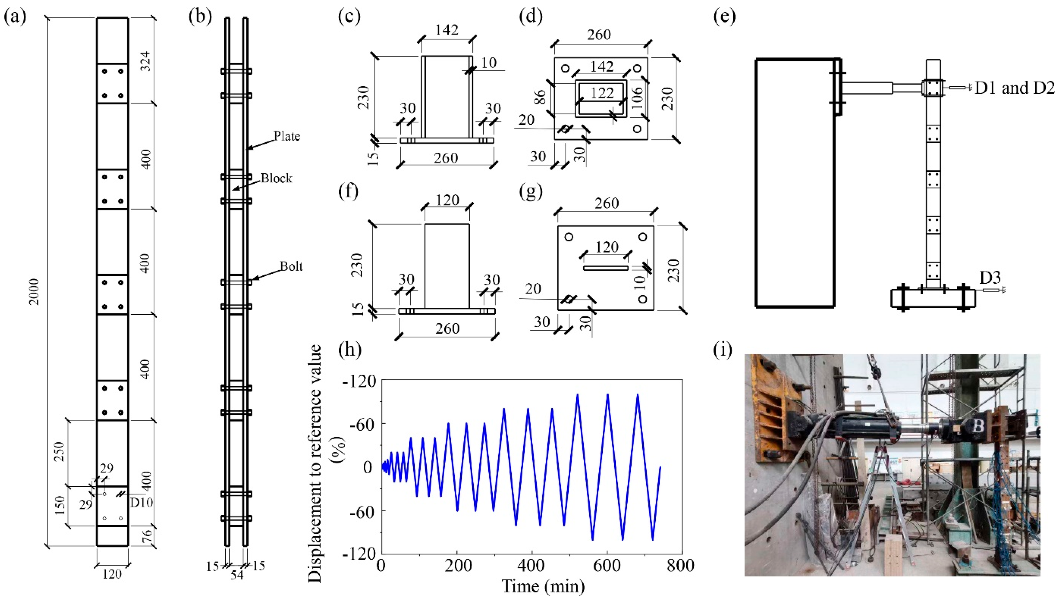
2.2.1. Test Piece Design

The design and manufacturing of the double-jointed columns are detailed below following a previous study [28] on the mechanical performance of double-jointed engineered bamboo beams. Two connection forms were carefully designed and tested: specimen S1 with an encased steel plate column base connection, and specimen S2 with a slotted-in steel plate column base connection. The prepared double-jointed columns were equal-section components, composed of two cladding plates and five clamping blocks, as shown in Figure 1a,b. The cross-sectional geometric dimensions of the cladding plate were 120 mm × 15 mm, and the height was 2000 mm; the geometric dimensions of the clamping block were 120 mm × 54 mm, and the height was 150 mm. The distance between the bottom surface of the bottom clamping block and the bottom surface of the cladding plate was 76 mm, and the distance between adjacent clamping blocks was 400 mm. The clamp block and the cladding plate were connected by bolts, and the diameter, side distance, and end distance of the bolts were 10 mm, 29 mm, and 29 mm, respectively. The cladding board and the clip were both made of bamboo scrimber, and the bolts were ordinary hexagonal bolts. Detailed information of the base connections of specimens S1 and S2 is shown in Figure 1c–g, respectively. The geometric size of the bottom steel plate was 260 mm × 230 mm and the thickness was 15 mm; this plate was connected to the section steel foundation through four ordinary bolts, each with a diameter of 20 mm. The height and thickness of the steel plate connected with the restructured bamboo were 230 mm and 10 mm, respectively, and the position of the bolt was determined according to the position of the bolt at the bottom of the bamboo scrimber column.

2.2.2. Test Loading and Measurements

The loading device and measurement methods are shown in Figure 1e,i. The column base connections were initially fixed on the ground, and then horizontal displacement was applied at the set loading point using an MTS dual-channel structural test system. The location of the loading point was the center point of the top clamp (the height of the loading point from the column base was 1750 mm), and the loading rate was controlled at 5 mm/min. The double-jointed engineered bamboo columns are generally used in houses of no more than 3 stories; the axial compressive load is not notable under such conditions. Therefore, no axial compressive load was applied during the tests. Displacement gauges D1 and D2 were used to measure the horizontal displacement of the loading head, and displacement gauge D3 was used to measure the horizontal displacement of the foundation.
The reversed cyclic loading scheme was determined according to the Code for Seismic Tests of Buildings JGJ/T 101-2015 [29], as shown in Figure 1h. The first five cycles were single variable amplitude loading, and the displacement amplitude gradually increased from 1.25%Δ to 10%Δ (Δ was taken as 60 mm). Subsequent loops included major and minor loop loads. The displacement amplitude of the main cycle gradually increased from 20%Δ to 100%Δ, and the displacement amplitude of the secondary cycles was identical to that of the main cycles. Loads were applied twice in the secondary cycle. After the displacement amplitude exceeded 100%Δ, the incremental displacement amplitude of the cycle was 20 mm. When the column was obviously damaged or the horizontal load dropped below 85% of the peak load, the loading stopped and the actuator returned to the initial loading point.

3. Results and Discussion

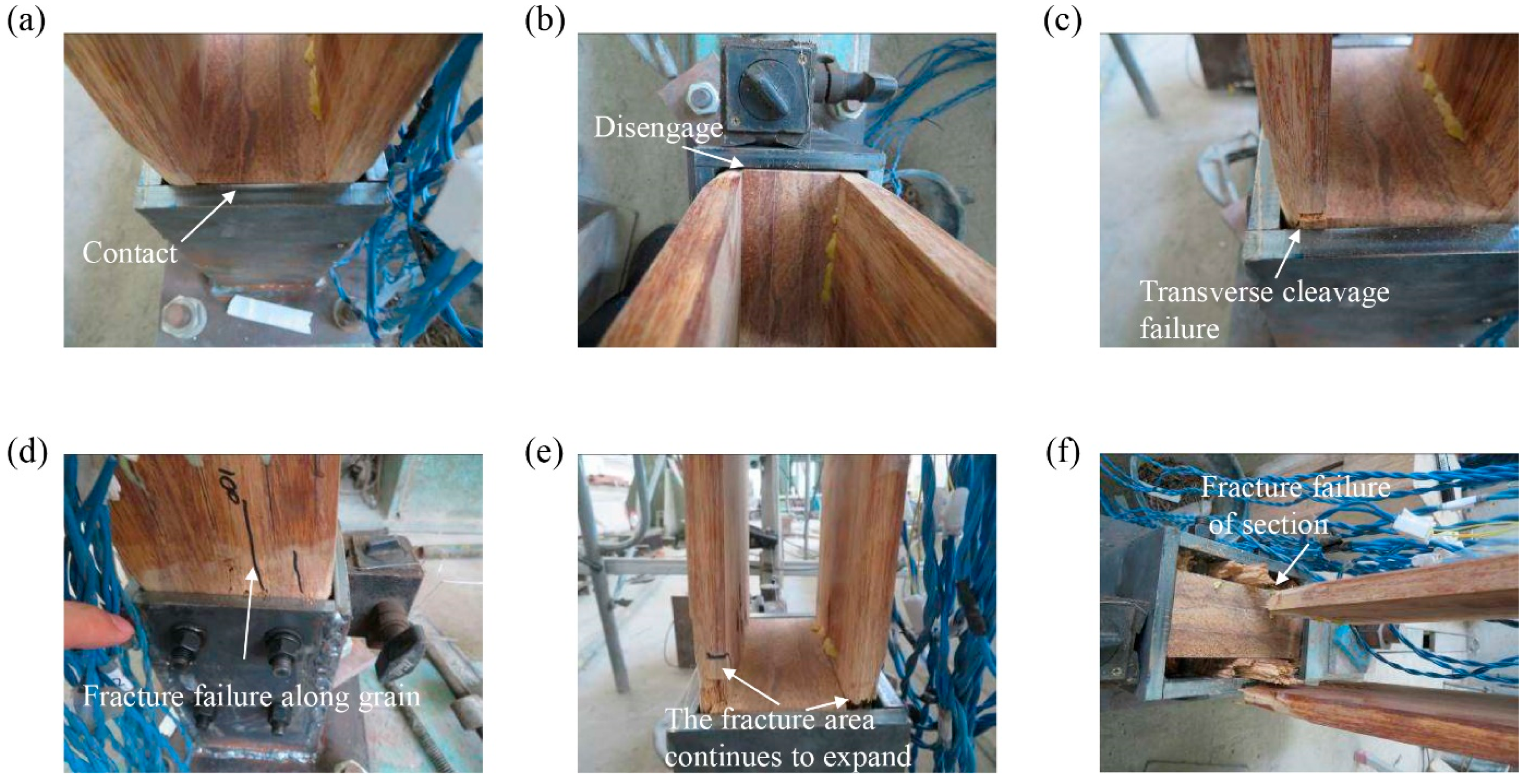
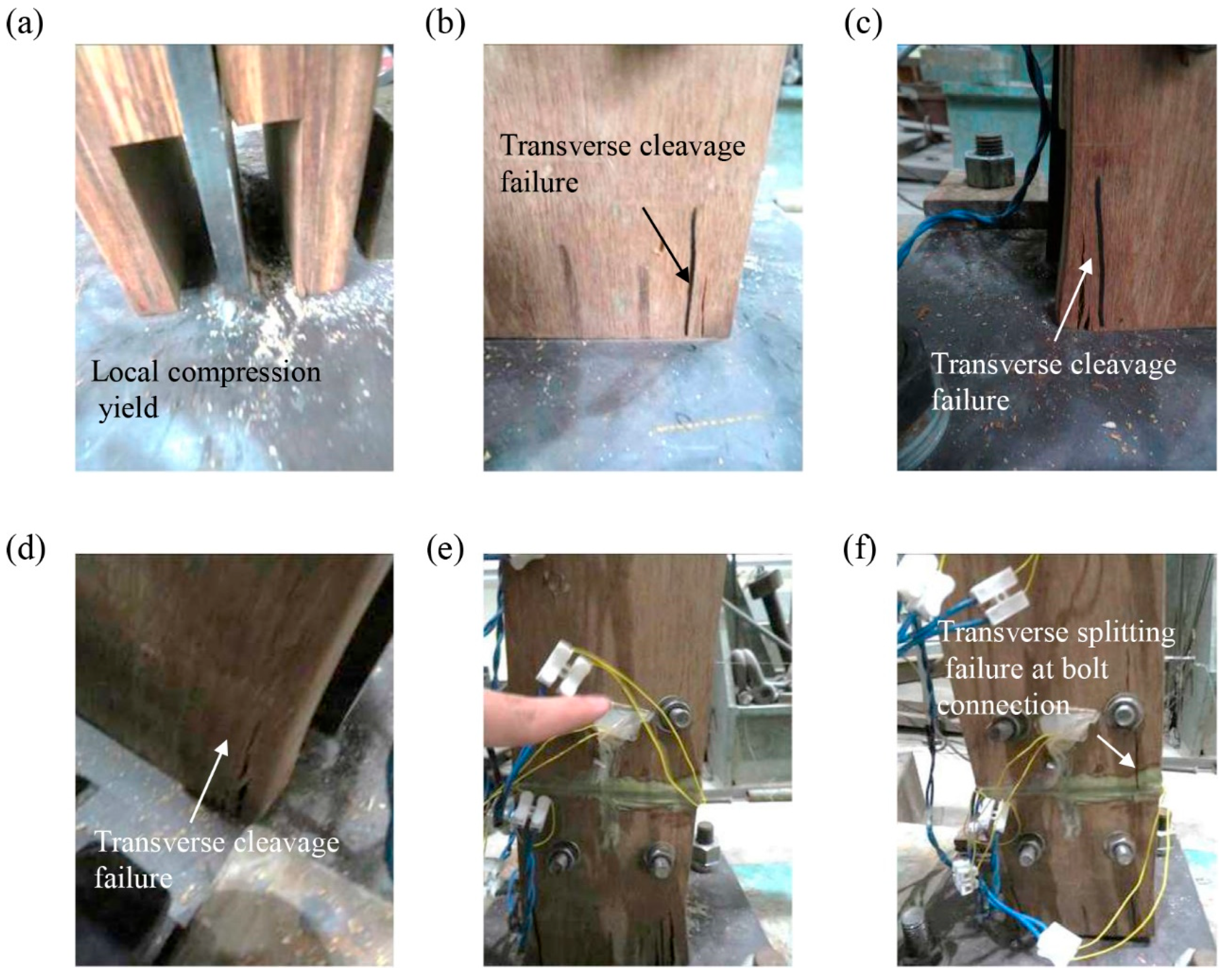
3.1. Experimental Phenomenon

The main failure modes of specimen S1 are shown in Figure 2. When the horizontal displacement of the loading point reached +24 mm, one side of the double-split column was in contact with the steel plate at the base of the column and the other side was separated from the steel plate at the base of the column (Figure 2a,b). When the horizontal displacement of the loading point reached −120 mm, transverse cleavage failure occurred near the encased steel plates (Figure 2c). When the horizontal displacement of the loading point reached +120 mm, the bamboo scrimber fractured along the grain at the tensile region between the bottom of the double-jointed column sheathing plate and the clamping block (Figure 2d). When the horizontal displacement of the loading point reached +140 mm, the splitting of the bamboo scrimber at the bottom of the cladding continued to propagate along the grain, and finally the entire cross-section was tensile fractured near the top of the encased steel plates due to the restraint provide by the encased steel plates (Figure 2e,g).
The main failure modes of specimen S2 are shown in Figure 3. When the horizontal displacement of the loading point reached +48 mm, local compression yielding and transverse grain splitting failure of the bamboo scrimber occurred at the contact between the bottom of the cladding plate on one side of the double-jointed column and the steel plate at the bottom of the column base connection (compression region) (Figure 3a,b). As the horizontal displacement of the loading point reached −80 mm, cross-grain splitting failure of the bamboo scrimber was observed at the contact between the bottom of the cladding plate on the other side of the double-jointed column and the steel plate at the bottom of the column base connection (compressed area) (Figure 3c,d). With increasing horizontal displacement, the width and length of the crack at the bottom of the cladding plate increased continuously. When the horizontal displacement of the loading point reached ±180 mm, cross-grain splitting failure of the bamboo scrimber appeared at the connection line of the bolts at the bottom of the cladding plate due to the low tensile strength perpendicular to the bamboo grain (Figure 3b,e).

3.2. Main Mechanical Performance Parameters

The load–displacement curves of each specimen were determined and the results are shown in Figure 4. Each specimen was in the linear elastic stage at the initial loading stage. With the continuous increase in the loading, the specimens entered the nonlinear stage. After the peak load was exceeded, the bearing capacity decreased rapidly for specimen S1. The key mechanical performance parameters were determined according to the skeleton curve of each tested specimen, as shown in Table 1. Maximum load Fmax and its corresponding displacement Smax were determined according to the peak point of the curve. The initial stiffness k was determined according to 40% of the maximum load and the corresponding displacement following the suggestions of related studies on the rotational behavior of the engineered bamboo connections [12,13]. For specimen S1, the failure load Fu and its corresponding displacement Su were taken as 85% of the maximum load and the corresponding displacement after the peak load [30]. For specimen S2, the failure load Fu and its corresponding displacement Su were determined as the maximum load and its corresponding displacement in the last main cycle (180 mm), since longitudinal splitting failure occurred in the cycle. Also, its deformability exceeded the range of the actuator. As a result, no descending section existed in the load–displacement curve. The yielding load Fy and its corresponding displacement Sy were determined according to the equivalent energy method (EEEP method) [30]. The ductility ratio of the specimen was taken as the ratio of the displacement corresponding to the ultimate load to the displacement corresponding to the yielding load.
As seen from Table 1, the initial stiffness of the encased steel plate column base connection specimen was 41.8% higher than that of the slotted-in steel plate column base connection specimen, and the specimens had a relatively similar bearing capacity on average. Both specimens exhibited brittle failure, and the ductility ratio was below 3.0.

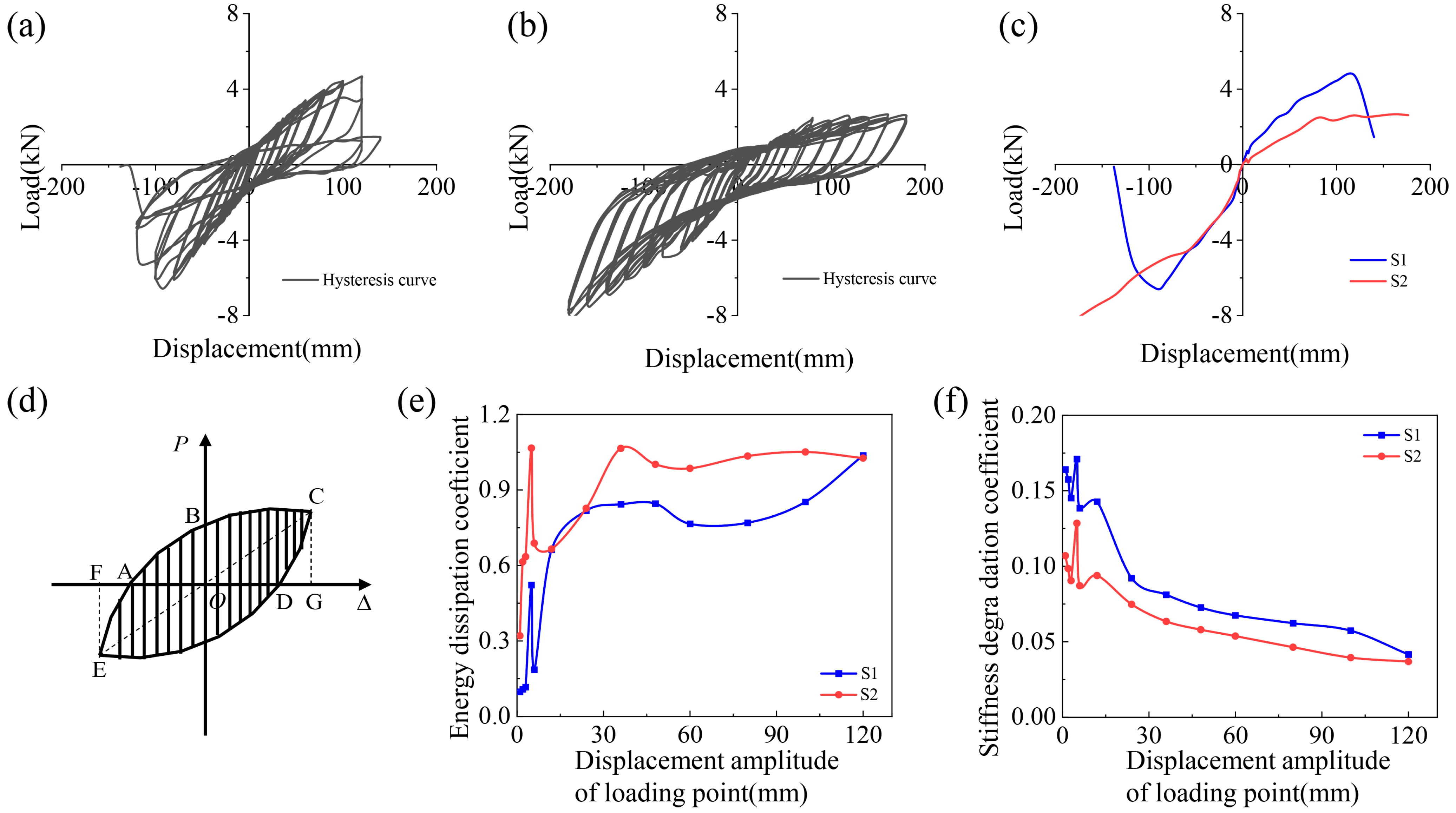
3.3. Energy Consumption Capacity

Energy dissipation performance can usually be characterized according to the energy dissipation coefficient, and can be expressed as:
E = S ABCDE S Δ OCG + Δ OEF
where S(ABCDE) represents the first hysteresis loop area (Figure 4d) of each cycle, and S(ΔOCG+ΔOEF) is the sum of the triangular areas corresponding to the peak point of the hysteresis loop.
The energy dissipation coefficient curve of each sample was determined and the results are shown in Figure 4e. A continuous decline in the stiffness degradation coefficient existed at the initial loadings due to the tough contact between the bamboo scrimber and the base steel plate. When the displacement amplitude of the loading point exceeded 20 mm, the energy dissipation coefficient of the specimen gradually stabilized.

3.4. Changes in Stiffness Degradation

According to Building Seismic Test Regulations JGJ/T 101-2015 [29], the slope of the line between the positive load peak points of the first hysteresis loop of each cycle was used to measure the degree of stiffness degradation, and can be expressed as:
K i = + F i + F i + Δ i + Δ i
where +Fi and −Fi represent the positive and negative maximum loads of the first hysteresis loop under the i-th cyclic loading, respectively; +Δi and −Δi are the horizontal displacements of the loading head, corresponding to +Fi and −Fi, respectively.
The stiffness degradation curves of S1 and S2 are shown in Figure 4f. For the two samples, a continuous decline in the stiffness degradation coefficient existed at the initial loadings due to the tough contact between the bamboo scrimber and the base steel plate. The stiffness degradation rate was relatively fast at the initial loading stage and then relatively slow at the later loading stage.

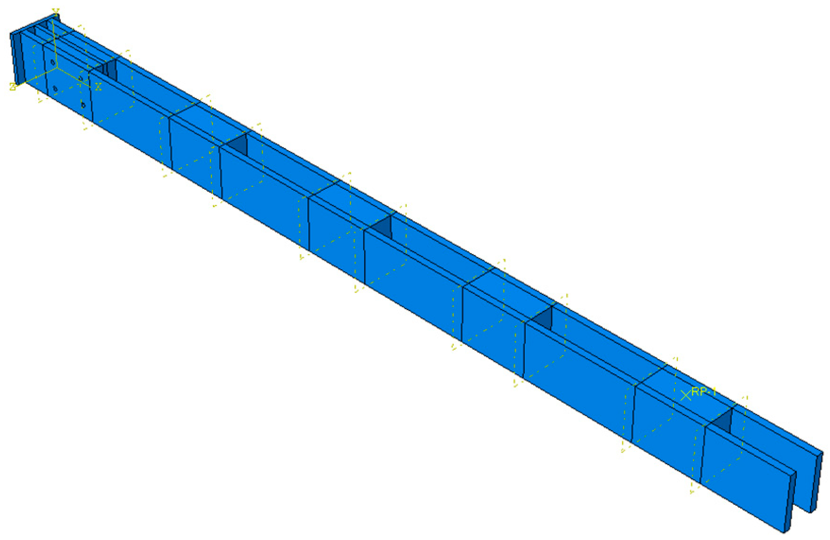
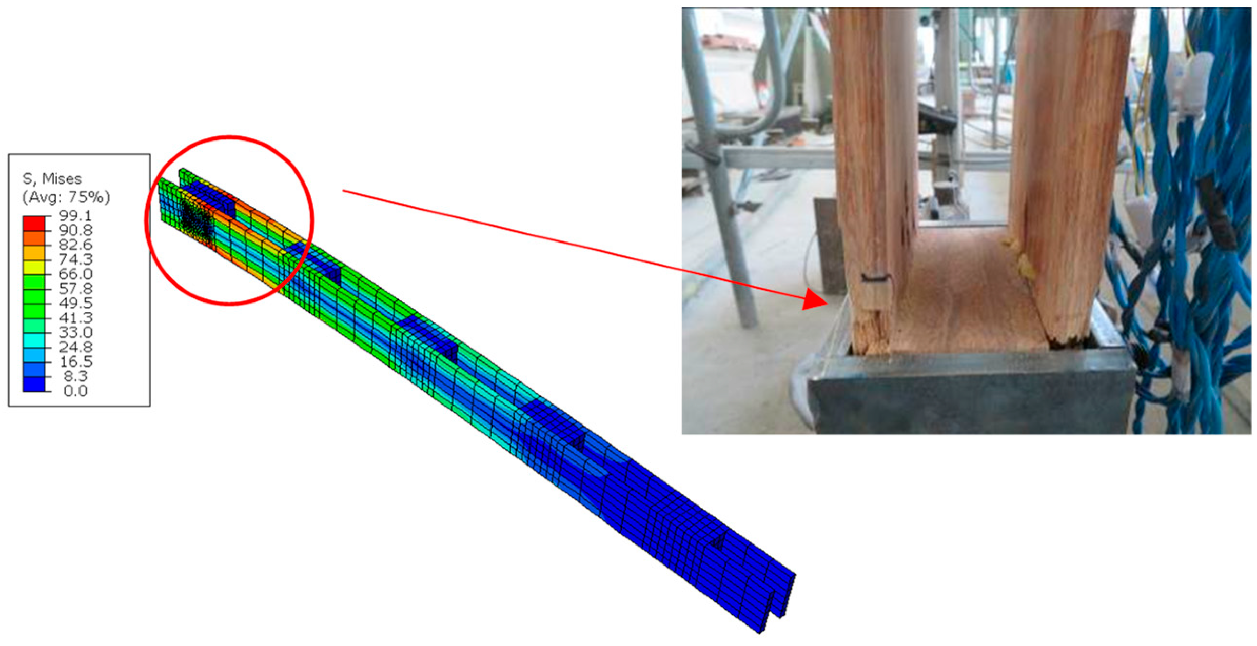
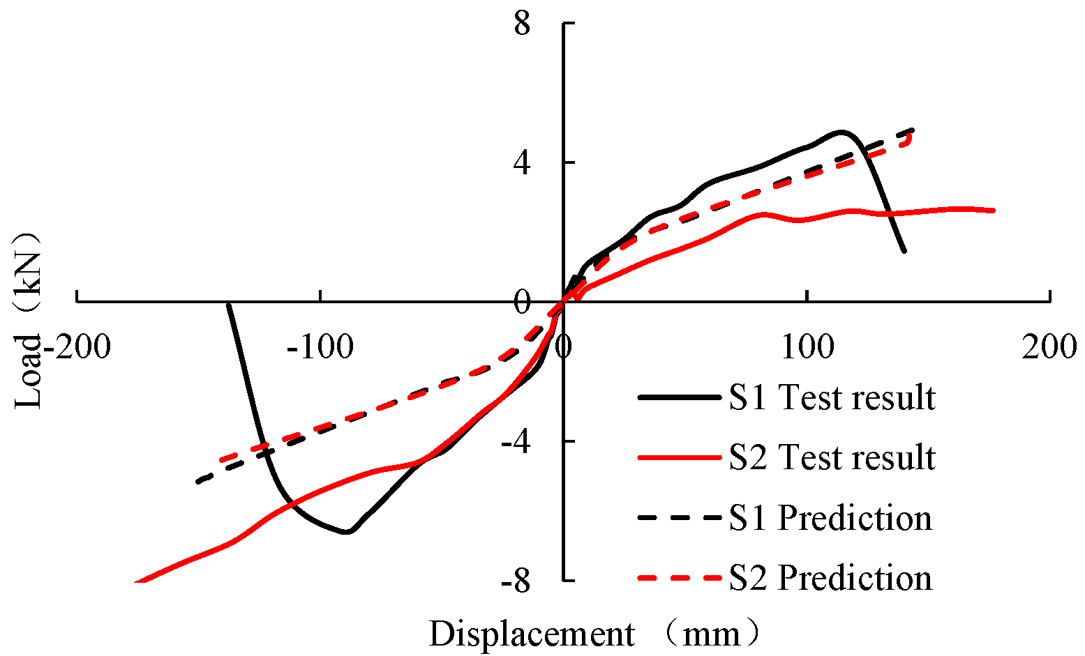
4. Numerical Simulation Analysis

An FEM analysis was conducted to predict the stiffness and ultimate capacity of the double-jointed engineered bamboo column specimens. The commercial finite element software ABAQUS was used to establish a finite element analysis model of bamboo double-jointed column members, as shown in Figure 5. Bamboo scrimber, bolts, and steel plates were simulated using a three-dimensional, eight-node hexahedron, reduced integration element (C3D8R element).
An ideal elastoplastic constitutive model was used to simulate bamboo scrimber, and the Hill yielding criterion was selected as the yielding criterion. The mechanical properties of the bamboo scrimber in the longitudinal direction were determined based on the small clear specimen test results following the Chinese specifications [28,29], since the material properties in the longitudinal direction played an important role in the seismic performance of the double-jointed engineered bamboo columns. The material properties of the bamboo scrimber in the transverse directions and the Poisson’s ratios were determined based on previous studies related to numerical simulations of the bolted connections [31]. The mechanical property parameters of the material are shown in Table 2. The steel plate and the bolt were simulated by the ideal elastic–plastic constitutive model, with an elastic modulus of 2 × 10⁵ MPa and yield strengths of 210 MPa and 640 MPa, respectively.
The contact surface between the bamboo scrimber and the steel plate was simulated by contact. A hard contact model and friction coefficient of 0.5 were considered for the interaction between the bolt and the foundation region. To ensure the convergence of the calculation, except for the bottom column base connections, the interactions between the rest of the cladding, clips, and bolts were simplified, and the Tie command was used for the simulation. A fixed constraint was applied to the bottom steel plate, and a horizontal displacement was applied to the middle of the top clamp through the reference point. The finite element simulation was loaded using a monotonic loading control simulation, since the reversed cyclic loading simulation was often terminated by the convergence problem.
Based on the simulation, the stress distribution of the bamboo scrimber is shown in Figure 6. The high-stress area of the specimen was mainly concentrated at the bottom cladding plate, which is very close to the test results. This indicates that the FEM model can effectively capture the failure modes of the specimens.
Load–displacement curves of the test results and numerical predictions are shown in Figure 7. It was found that the FEM models could capture the initial stiffness and the nonlinear ascending stage of each specimen.
The numerical simulation results and the experimental test results are compared in Table 3. The findings suggest that the finite element model can reasonably predict the mechanical performance of the bamboo double-jointed column components, with a prediction error for the ultimate bearing capacity of the components within 12%, which is sufficient to meet the requirements of engineering accuracy.

5. Conclusions

(1)
The type of the column base connection significantly affected the failure modes of the double-jointed engineered bamboo columns. The main failure mode of specimen S1, with an encased steel plate connection, was longitudinal tensile fracture failure of the bamboo scrimber section at the bottom of the sheathing plate; and the main failure mode of S2, with a slotted-in steel plate connection, was longitudinal splitting at the bolt connection at the bottom of the sheathing plate.
(2)
The initial stiffness of the encased steel plate column base connection, specimen S1, was 41.8% higher than that of the slotted-in steel plate column base connection, specimen S2, and the two specimens exhibited relatively similar load-bearing capacities on average. Both the two specimens exhibited brittle failure mode, and the ductility ratio was below 3.0.
(3)
The energy dissipation coefficient in the initial stage of loading increased continuously with the increase in the displacement amplitude of the loading point for both samples. When the displacement amplitude of the loading point exceeded 20 mm, the energy dissipation coefficient of the specimen gradually stabilized. The stiffness degradation rate was relatively fast during the initial stage of loading and relatively slow during the later stage of loading.
(4)
The finite element model exhibited good prediction accuracy for the ultimate bearing capacity of the specimens, with error within 12%, thus meeting the requirements for engineering accuracy.
It should be noted that the stiffness and load-carrying capacity of single columns were low; high-performance braces should be used in engineered bamboo structures to enhance the lateral stiffness and load-carrying capacity of the whole frame.

Author Contributions

Conceptualization, F.C. and G.W.; Methodology, Y.L.; Formal analysis, D.L.; Investigation, S.H.; Data curation, M.W. All authors have read and agreed to the published version of the manuscript.

Funding

This work was financially sponsored by Fundamental Research Funds for the International Centre for Bamboo and Rattan (1632021020\1632019013) and Shanghai Rising-Star Program (Grant No. 23QB1404400).

Data Availability Statement

If readers require data from this article, please contact the corresponding author.

Acknowledgments

The authors are greatly indebted to the anonymous reviewers for their valuable comments and suggestions, which helped in improving the overall quality of this manuscript greatly.

Conflicts of Interest

The authors declare that they have no conflict of interest to report regarding the present study.

References

  1. Zhang, Y.; Yu, W.; Kim, N.; Qi, Y. Mechanical performance and dimensional stability of bamboo fiber-based composite. Polymers 2021, 13, 1732. [Google Scholar] [CrossRef] [PubMed]
  2. Rao, F.; Ji, Y.; Li, N.; Zhang, Y.; Chen, Y.; Yu, W. Outdoor bamboo-fiber-reinforced composite: Influence of resin content on water resistance and mechanical properties. Constr. Build. Mater. 2020, 261, 120022. [Google Scholar] [CrossRef]
  3. Cui, H.X.; Guan, M.J.; Zhu, Y.X.; Zhang, Z.Z. The flexural characteristics of prestressed bamboo slivers reinforced parallel strand lumber (PSL). In Key Engineering Materials; Trans Tech Publications Ltd.: Stafa, Switzerland, 2012; Volume 517, pp. 96–100. [Google Scholar]
  4. Duan, Y.; Zhang, J.; Tong, K.; Wu, P.; Li, Y. The effect of interfacial slip on the flexural behavior of steel-bamboo composite beams. Structures 2021, 32, 2060–2072. [Google Scholar] [CrossRef]
  5. Zhou, H.; Wei, X.; Smith, L.M.; Wang, G.; Chen, F. Evaluation of uniformity of bamboo bundle veneer and bamboo bundle laminated veneer lumber (BLVL). Forests 2019, 10, 921. [Google Scholar] [CrossRef]
  6. Chen, F.; Jiang, Z.; Wang, G.; Li, H.; Simth, L.M.; Shi, S.Q. The bending properties of bamboo bundle laminated veneer lumber (BLVL) double beams. Constr. Build. Mater. 2016, 119, 145–151. [Google Scholar] [CrossRef]
  7. Chen, F.; Deng, J.; Li, X.; Wang, G.; Smith, L.M.; Shi, S.Q. Effect of laminated structure design on the mechanical properties of bamboo-wood hybrid laminated veneer lumber. Eur. J. Wood Wood Prod. 2017, 75, 439–448. [Google Scholar] [CrossRef]
  8. Zhou, H.; Wang, G.; Chen, L.; Yu, Z.; Smith, L.M.; Chen, F. Hydrothermal aging properties of three typical bamboo engineering composites. Materials 2019, 12, 1450. [Google Scholar] [CrossRef]
  9. Sinha, A.; Way, D.; Mlasko, S. Structural performance of glued laminated bamboo beams. J. Struct. Eng. 2014, 140, 04013021. [Google Scholar] [CrossRef]
  10. Li, H.-T.; Su, J.-W.; Zhang, Q.-S.; Deeks, A.J.; Hui, D. Mechanical performance of laminated bamboo column under axial compression. Compos. Part B Eng. 2015, 79, 374–382. [Google Scholar] [CrossRef]
  11. Li, H.; Wu, G.; Zhang, Q.; Deeks, A.J.; Su, J. Ultimate bending capacity evaluation of laminated bamboo lumber beams. Constr. Build. Mater. 2018, 160, 365–375. [Google Scholar] [CrossRef]
  12. Leng, Y.; Xu, Q.; Harries, K.A.; Chen, L.; Liu, K.; Chen, X. Experimental study on mechanical properties of laminated bamboo beam-to-column connections. Eng. Struct. 2020, 210, 110305. [Google Scholar] [CrossRef]
  13. Leng, Y.; Wang, Z.; Xu, M. Experimental study and analysis on rotational behavior of bamboo scrimber beam-to-column bolted connections. J. Struct. Eng. 2021, 147, 04021122. [Google Scholar] [CrossRef]
  14. Cui, Z.; Huang, D.; Huang, Z.; Zhuang, M.-L.; Xu, M. Experimental investigation and calculation method for the bearing capability of bolt steel-to-laminated bamboo connections under the coupling of bending moment and shear force. J. Build. Eng. 2022, 59, 105126. [Google Scholar] [CrossRef]
  15. Chen, G.; Yang, W.; Zhou, T.; Yu, Y.; Wu, J.; Jiang, H.; Li, X.; Zhang, Y. Experiments on laminated bamboo lumber nailed connections. Constr. Build. Mater. 2021, 269, 121321. [Google Scholar] [CrossRef]
  16. Hong, C.; Li, H.; Yang, D.; Li, X.; Lorenzo, R.; Ashraf, M. Laminated bamboo lumber in compression perpendicular to the grain direction: Experimental investigation and the finite element analysis. Wood Mater. Sci. Eng. 2023, 18, 1302–1318. [Google Scholar] [CrossRef]
  17. Tang, G.; Yin, L.; Li, Z.; Li, Y.; You, L. Structural behaviors of bolted connections using laminated bamboo and steel plates. Structures 2019, 20, 324–339. [Google Scholar] [CrossRef]
  18. Khoshbakht, N.; Clouston, P.L.; Arwade, S.R.; Schreyer, A.C. Computational modeling of laminated veneer bamboo dowel connections. J. Mater. Civ. Eng. 2018, 30, 04017285. [Google Scholar] [CrossRef]
  19. Correal, J.F.; Ramirez, F.; Gonzalez, S.; Camacho, J. Structural behavior of glued laminated guadua bamboo as a construction material. In Proceedings of the 11th World Conference on Timber Engineering, Trentino, Italy, 20–24 June 2010. [Google Scholar]
  20. Correal, J.F.; Echeverry, J.S.; Ramírez, F.; Yamín, L.E. Experimental evaluation of physical and mechanical properties of Glued Laminated Guadua angustifolia Kunth. Constr. Build. Mater. 2014, 73, 105–112. [Google Scholar] [CrossRef]
  21. Sharma, B.; Gatóo, A.; Ramage, M.H. Effect of processing methods on the mechanical properties of engineered bamboo. Constr. Build. Mater. 2015, 83, 95–101. [Google Scholar] [CrossRef]
  22. Wang, M.; Song, X.; Gu, X.; Zhang, Y.; Luo, L. Rotational behavior of bolted beam-to-column connections with locally cross-laminated glulam. J. Struct. Eng. 2015, 141, 04014121. [Google Scholar] [CrossRef]
  23. Ross, R.J. Wood Handbook: Wood as an Engineering Material; Department of Agriculture: Washington, DC, USA, 2010.
  24. Lam, F.; Schulte-Wrede, M.; Yao, C.; Gu, J. Moment resistance of bolted timber connections with perpendicular to grain reinforcements. In Proceedings of the 10th World Conference on Timber Engineering (WCTE), Miyazaki, Japan, 2–5 June 2008. [Google Scholar]
  25. Van der Lugt, P.; Van den Dobbelsteen, A.; Janssen, J. An environmental, economic and practical assessment of bamboo as a building material for supporting structures. Constr. Build. Mater. 2006, 20, 648–656. [Google Scholar] [CrossRef]
  26. GB/T 1936.2-2009; Method for Determination of the Modulus of Elasticity in Static Bending of Wood. China Standardization Management Committee: Beijing, China, 2009.
  27. GB/T 1936.1-2009; Method of Testing in Bending Strength of Wood. China Standardization Management Committee: Beijing, China, 2009.
  28. Chen, F.; Li, D.; Zhou, H.; Sun, T.; You, H.; Chen, L.; Yin, Y.; Sun, F.; Wang, G. Development of bamboo-based double beam and its application to prefabricated construction. World For. Res. 2019, 32, 61–66. (In Chinese) [Google Scholar]
  29. JGJ/T 101-2015; Specification for Seismic Test of Buildings. China Architecture and Building Press: Beijing, China, 2018.
  30. Jorissen, A.; Fragiacomo, M. General notes on ductility in timber structures. Eng. Struct. 2011, 33, 2987–2997. [Google Scholar] [CrossRef]
  31. Wang, M.; Song, X.; Gu, X.; Tang, J. Bolted glulam beam-column connections under different combinations of shear and bending. Eng. Struct. 2019, 181, 281–292. [Google Scholar] [CrossRef]
Figure 1. Experimental design. (a,b) Geometric dimensions of double-jointed columns (unit: mm). (c,d,f,g) Geometric dimensions of column base connections (unit: mm). (e,i) Test loading and data measurement scheme. (h) Reversed cyclic loading scheme.
Buildings 13 02342 g001
Figure 2. The main failure modes of specimen S1. (a,b) Horizontal displacement +24 mm. (c) Horizontal displacement −120 mm. (d) Horizontal displacement +120 mm. (e) Horizontal displacement −140 mm. (f) Horizontal displacement +140 mm.
Buildings 13 02342 g002
Figure 3. The main failure modes of specimen S2. (a,b) Horizontal displacement +48 mm. (c,d) Horizontal displacement −80 mm. (e,f) Horizontal displacement +180 mm.
Buildings 13 02342 g003
Figure 4. The main mechanical properties, energy dissipation capacities, and stiffness degradation laws of the samples. (a) The load–displacement curve of specimen S1 under reverse cyclic loading. (b) The load–displacement curve of specimen S2 under reverse cyclic loading. (c) Backbone curves of S1 and S2 under reversed cyclic loads. (d) Typical hysteresis curve. (e) Energy dissipation coefficient curves of S1 and S2. (f) Stiffness degradation curves of S1 and S2.
Buildings 13 02342 g004
Figure 5. Finite element analysis model of the double-column columns.
Buildings 13 02342 g005
Figure 6. Stress distribution of the simulated bamboo scrimber (Unit: MPa).
Buildings 13 02342 g006
Figure 7. Load–displacement curves of the test results and numerical predictions.
Buildings 13 02342 g007
Table 1. Key mechanical performance parameters.
Specimen IDkFysyFmaxsmaxFusuμ
/kN/mm/kN/mm/kN/mm/kN/mm
S1+0.074.0056.14.67120.13.97124.52.2
S1−0.115.4548.06.5792.25.59110.12.3
Average0.094.7352.15.62106.14.78117.32.3
S2+0.032.4872.82.66160.12.62176.52.4
S2−0.096.1965.58.11175.88.11175.82.7
Average0.064.3469.15.39168.05.37176.22.6
Note: + and − indicate positive and negative directions.
Table 2. Mechanical property parameters of the bamboo scrimber.
E11E22E33v12v31v23
/MPa/MPa/MPaDimensionlessDimensionlessDimensionless
13,2605975970.300.050.40
G12G13G23f11f22f33
/MPa/MPa/MPa/MPa/MPa/MPa
1550123090014014.014.0
f12f13f23
/MPa/MPa/MPa
21.021.021.0
Table 3. Comparison of numerical simulation and experimental results.
SampleUltimate Bearing Capacity
Test Mean
/kN
Numerical Simulation Results
/kN
Simulation Error
/%
S15.74 5.15 −10.2
S25.39 4.78 −11.3
Disclaimer/Publisher’s Note: The statements, opinions and data contained in all publications are solely those of the individual author(s) and contributor(s) and not of MDPI and/or the editor(s). MDPI and/or the editor(s) disclaim responsibility for any injury to people or property resulting from any ideas, methods, instructions or products referred to in the content.

