Article

Cable Force Calculation of Cable Hoisting of CFST Arch Bridge Research

1
Faculty of Civil Engineering and Mechanics, Kunming University of Science and Technology, Kunming 650500, China
2
Yunnan Earthquake Engineering Research Institute, Kunming 650500, China
3
School of Civil Engineering, Putian University, Putian 351100, China
4
Fujian Nanyu Engineering Construction Co., Ltd., Sanming 365000, China
*
Author to whom correspondence should be addressed.
Buildings 2023, 13(9), 2370; https://doi.org/10.3390/buildings13092370
Submission received: 28 July 2023 / Revised: 8 September 2023 / Accepted: 10 September 2023 / Published: 18 September 2023

Abstract

:
To effectively control the stress state and spatial alignment of arch ribs in the cable hoisting construction of a long-span, concrete-filled, steel tube arch bridge and ensure the safety of the structure, it is necessary to calculate and determine the appropriate cable force. Based on the actual project of a double-span, concrete-filled, steel tubular arch bridge, the construction stage of the left span of the bridge from the beginning of construction to the closure is taken as an example. The linear control method of “quiet do not move” is adopted. Based on the principle that the vertical displacement of the front end of the installed segment caused by the self-weight of the new hoisting segment is equal to the vertical displacement of the front end of the previous segment caused by the tension of the new hoisting segment, the tension cable force is calculated by forward iteration. Finally, based on the theory of the stress-free state method, the ideal linear design of the structure was achieved. The results show that after the closure of the bridge, the error range of the cable tension force is −13.33–15.40% on the left bank and −8.37–11.00% on the right bank. The elevation error of the arch rib is −0.003–0.043 m on the left bank and −0.007–0.032 m on the right bank. The overall stress error of the bridge arch is ±7.0 MPa. The error between the theoretical value and the actual value is within the scope of the specification requirements, which meets the specification requirements. After the closure, the arch shape of the bridge meets the smooth requirements.

1. Introduction

Long-span, concrete-filled, steel tube arch bridges usually use the cable-hoisting method to erect the arch ribs [1]. In the process of the cantilever assembly of arch ribs, with the tension of the segmental cable force, the number of structural static indeterminate increases gradually, the system changes constantly, and the construction control is difficult [2]. The cable tension is the only way to adjust the alignment of the bridge. The cable force has a great influence on the alignment of the arch. Therefore, how to determine the reasonable cable force is a key problem in the construction of the arch bridge [3,4].
To calculate the cable force of a concrete-filled steel tube arch bridge, many experts have conducted a lot of research on it [5,6]. To avoid the tedious work of repeated cable adjustment in construction, Zhang Zhicheng et al. [7] used the ANSYS optimization module and life and death unit function optimization to obtain the best cable force. Liu Shaoping [8] calculated the one-time cable tensioning method and pre-lifting amount of the Daning River Bridge based on the cable tension method and the zero-order optimization method. Zhou Yin et al. [9] introduced the arch-forming control method based on the precise control of unstressed parameters and constructed the arch-forming calculation theory method of a steel tube coagulation arch bridge. Gu Ying et al. proposed the linear control principle of “high rather than low, quiet rather than moving” and a new calculation method for cable force, which solved the problem of large cable force deviation and difficult linear adjustments in the process of arch rib erection [10]. In summary, the cable force of the tension cable is very important to the later state of the bridge structure when the arch rib of the concrete-filled steel tube arch bridge is assembled. Although many scholars are committed to the study of the calculation of the cable force of the steel tube arch rib in cable hoisting construction, there are few references for the calculation of the cable force of a long-span bridge (such as the 410 m span of this paper). Therefore, this paper takes the calculation of the arch rib cable force of a long-span, concrete-filled steel tube arch bridge as an example to enrich the literature in this field.
Based on the actual project, this paper controls the arch bridge alignment based on the principle of “quiet do not move” and uses the forward iteration method to calculate the tensioned cable force when the arch rib of the arch bridge is assembled to obtain the ideal cable force value through calculation and guide the bridge construction process. This is performed so that the smoothness of the arch bridge after closure meets the requirements, providing a reference for the same type of project.

2. Calculation of Arch Rib Cable Force

When the cantilever tangent assembly method is used to assemble the arch rib segment, the arch rib can obtain the corresponding installation line shape after tensioning the appropriate cable force so that the arch rib can reach or approach the ideal bare arch line shape after closing and removing the buckle cable. However, with the continuous assembly of the arch rib, the angle between the buckle and the arch rib is constantly changing, so the tension of the buckle cable force also changes. The magnitude of the cable force will directly affect the safety of the arch rib assembly process and the accuracy of the assembly condition prediction. Therefore, determining a reasonable cable force is the key to ensuring the calculation accuracy and smooth closure of the arch bridge [11]. The traditional mechanical methods in the calculation of the cable force mainly include: the methods of moment balance, zero displacement method [12], zero-torque method [13], Elastic-rigid support method [14], etc. Of course, with the continuous deepening of the application of information technology, it is also possible to determine the size of the cable force through structural health monitoring (SHM) technology [15]. This technology can monitor the cable force of the tensioned cable in real-time. When the cable force changes, engineers can use the information provided by the detection system [16] to formulate a plan for whether to adjust the size of the cable force to ensure the safety of the bridge construction process and subsequent operation [17].
Determining cable forces through structural health monitoring techniques is a commonly used method across various types of structures, including bridges, buildings, and mechanical equipment. This approach relies on the utilization of sensors and monitoring technologies to capture specific parameters of the structure, enabling the estimation of cable forces through data analysis. Here is a general overview of determining cable forces through health monitoring [18,19]: (1) Appropriate sensors such as strain gauges, pressure sensors, deflection sensors, accelerometers, etc., are installed on the structure to measure physical or dynamic parameters related to cable forces. (2) Data collected by the sensors is acquired and logged. This is often conducted through data acquisition units or wireless sensor networks. (3) By analyzing the data, the structural response can be inferred, such as changes in strain, vibration frequencies, etc. These responses are related to the forces or cable forces acting on the structure. (4) Based on known structural properties and mechanical models, mathematical models of the structure are developed using the acquired response data. This process incorporates structural characteristics and domain knowledge.
For example, the relationship between the cable strain ε and the tension T can be expressed by the following Formula (1):
ε = T / ( A × E )
where A represents the cross-sectional area of the cable and E represents Young’s modulus of the cable material.
Regarding the relationship between frequency and stiffness, the natural frequency (f) of a structure is related to its stiffness (k) and mass (m) through the following Formula (2):
f = ( 1 / 2 π ) × k / m
where f is the natural frequency in Hz, k is the stiffness coefficient in N/m, and m is the mass of the structure in kg.
Utilizing the established mathematical models and the results of data analysis, cable forces acting on the structure are estimated from the structural responses (5).
The commonly used cable force calculation methods are the forward analysis method [20] and the forward iteration method [21]. The forward analysis method is based on the actual structure construction sequence step by step to calculate and finally obtain the bridge structure stress state method. The forward iteration method is used to determine the reasonable construction state of the bridge through the forward analysis of the large cycle. Its calculation feature is to give each design variable an initial assumed value and then strictly follow the actual construction sequence using step-by-step structural analysis. According to the calculation results, the value of the initial design variable is modified to iterate until the objective function achieves satisfactory calculation accuracy. The calculations in this paper will use the forward iteration method to determine the cable force of the bridge construction stage through 1–2 iterations.

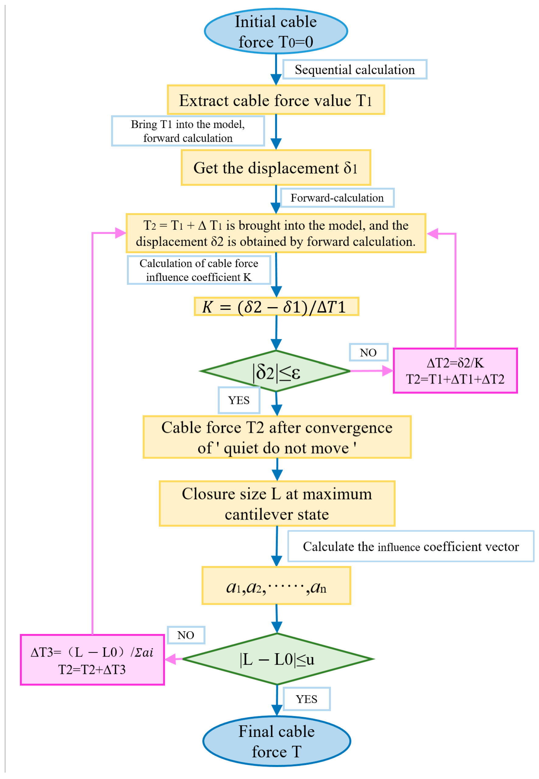
2.1. Calculation Principle

The arch rib alignment is controlled according to the principle of “quiet do not move“; that is, after the cable tension of the new arch rib segment, the vertical displacement of the adjacent arch rib segment remains basically unchanged. This method has the following advantages: (1) prevents the temporary joint of the flange plate in the pipe from being subjected to large bending moment and shear force, resulting in an increase in the weld width and the generation of misalignments; (2) prevents the temporary hinge of the arch foot from large rotations in theory and reduces the calculation error caused by the inconsistency between the actual rotation condition and the ideal hinge position; (3) reduces the displacement of the buckle point of the tensioned buckle cable, the change in the buckle cable force is small, and the difficulty of the deviation control of the buckle tower is reduced; (4) the cable force is tensioned once without repeated adjustment. The calculation formulae are shown below:
T n + 1 = T n + δ n / k
| δ n + 1 | ε
where T is the cable force; n is the number of iterations; δ is the vertical displacement (positive downward) generated at the front end of the previous segment when the cable tension is in the new stage; and k is the influence coefficient of cable force, the calculation method is k = ( δ n + 1 δ n ) / Δ T n . Among them, δn + 1 is the vertical displacement of the front end of the previous segment after the (n + 1) th iteration. When it is less than the allowable error ε, it can be considered that the cable force Tn meets the requirements.
According to the obtained cable force, using the influence matrix method [22] to consider the influence coefficient of the cable force on the closure size, the adjusted cable force is obtained. For example, in the tension stage of the jth segment, the displacement di of the control point i satisfies the following formula:
d i = a i j T j + w g i + w l i
where aij is the displacement variation of control point i when the unit force (1 kN) is applied to the j section of the cable, and wg and wl are the influences of the dead weight load and other construction loads on control point i.
We rewrite it into a matrix form:
D = a T + W g + W l
where [a] is the influence matrix of the vertical displacement of each control point when the unit cable force is tensioned in each segment. In cable-stayed suspension construction, the cable force can only adjust the displacement of the installed segment, and the subsequent uninstalled segment will not be affected by the current cable tension. Therefore, [a] is a triangular matrix:
a = a 11 a 12 a 1 j 0 a 22 a 2 j 0 0 a i j

2.2. Calculation Method

① Based on the principle that the downward displacement of the self-weight of the new hoisting segment to the front end of the adjacent segment and the upward displacement of the front end of the adjacent segment caused by the tension of the new segment are equal, the new tension cable force is iteratively solved. Because the geometric nonlinearity of the arch bridge has little effect on the calculation, it can converge after 1–2 iterations. ② According to the cable force calculated in the first step, the tangent assembly calculation is carried out, and the calculated size, L, of the closure gap and the theoretical length, L0, of the closure section in the maximum cantilever state are compared. If L = L0, according to the theory of the unstressed state method, the calculation of the bare arch alignment after the closure of the loose cable will be equal to the ideal bare arch alignment. ③ If there is a big difference between L and L0, the cable force calculated in the first step needs to be adjusted. First, the influence coefficient of each cable on the size of the closure is calculated, and then the coefficient is introduced for iterative calculation.
The advantage of this method is that the alignment of the arch bridge does not change much during the construction of the arch rib, and the alignment during the closure is similar to the manufacturing alignment. When the buckle cable is removed, the bare arch alignment is in good agreement with the ideal bare arch alignment, and the size error of the closure is small, which can meet the requirements of the ideal bare arch alignment. The flow chart of cable force calculation is shown in Figure 1.

3. Engineering Application

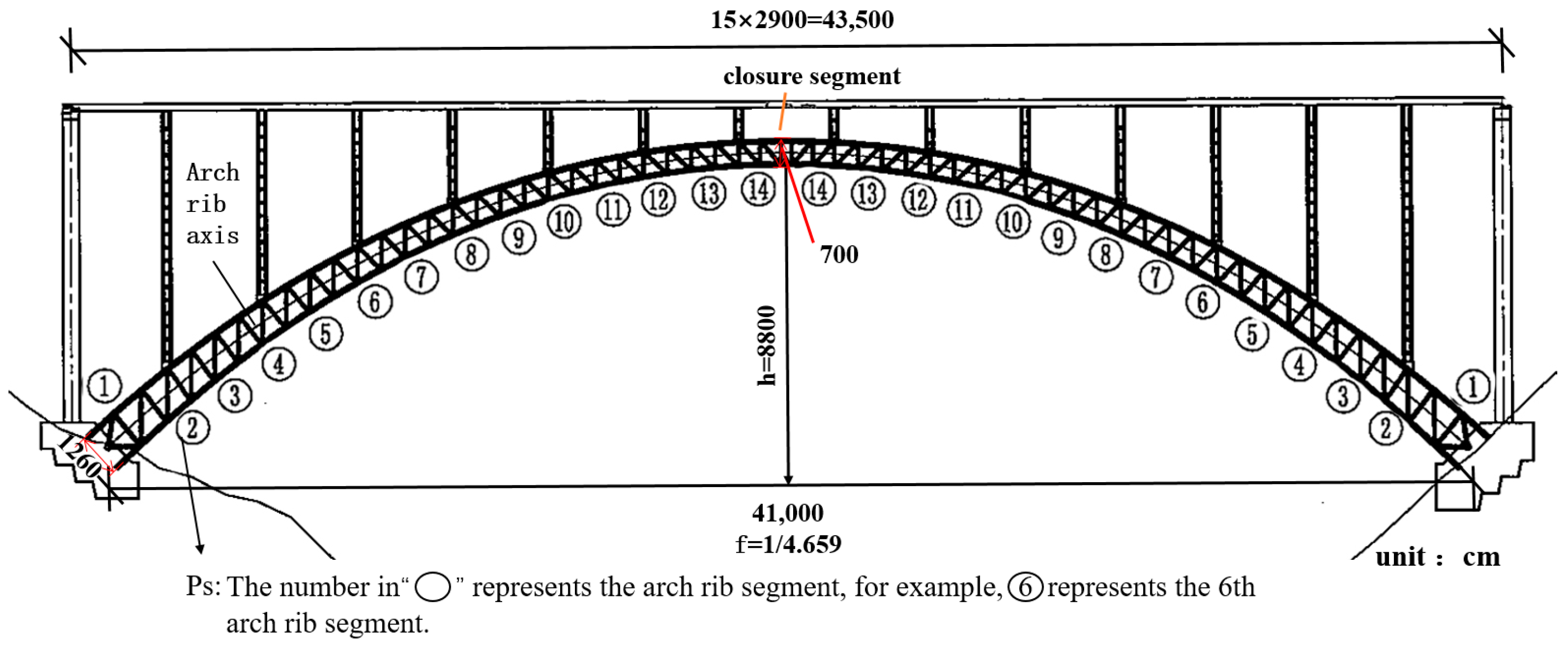
3.1. Engineering Situations

The main bridge of a double-width highway deck, concrete-filled steel tube arch bridge adopts a concrete-filled, steel tube variable cross-section truss arch with a calculated span of 410 m. The arch axis is catenary, the arch axis coefficient is m = 1.54, the height is h = 88 m, and the span ratio is f = 1/4.659. The main arch ring adopts a space truss structure with equal width and variable height. The width of a single arch rib is 10 m (middle to middle), and the section height changes from 7 m at the vault to 12.6 m at the arch foot (middle to middle). The overall layout of the bridge is shown in Figure 2, and the arch rib section is shown in Figure 3. The main arch ring section is divided into 14 sections from the arch foot to the vault, and the whole bridge is divided into 58 sections (including 2 closure sections). The maximum lifting weight of the section is about 230 t. To make it easy for the main arch ring to adjust the elevation and alignment during the hoisting process, the arch foot joint adopts a vertically rotatable hinge connection method, and the steel pipe arch rib is constructed by the cable hoisting and cable-stayed methods.

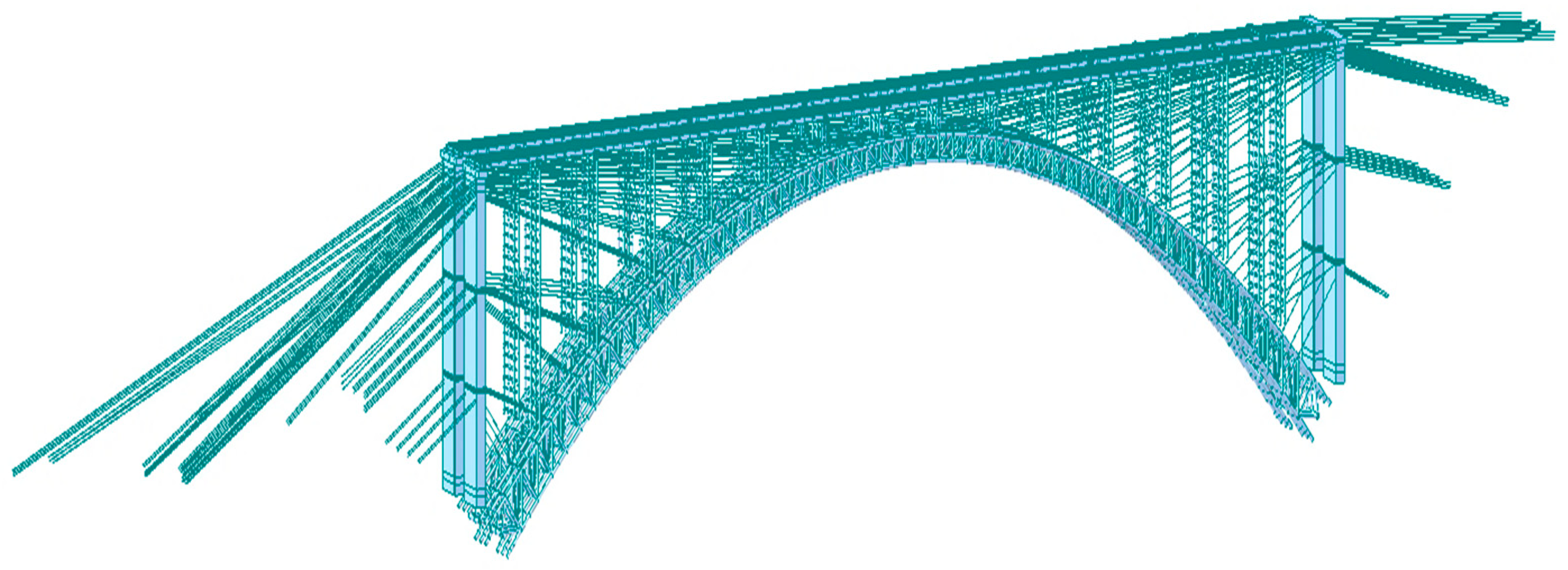
3.2. The Finite Element Model Calculation

Using Midas/Civil 2021 finite element software, the whole bridge is discretized into 11,694 beam elements and 232 truss elements. The arch rib, wind bracing, arch column, capping beam, and longitudinal and transverse beams of the bridge deck system of the arch bridge are simulated by beam elements, the buckle anchor cable is simulated by truss element, and the junction pier, transverse brace, and diagonal brace are simulated by beam elements. In the setting of boundary conditions, the bottom of the junction pier, the arch foot, and the anchor end of the anchor cable are set as consolidation constraints. Rigid connections are used between the arch column and the arch rib and between the capping beam and the arch column. The elastic connection is used to simulate the bearing between the steel longitudinal beam and the cover beam. In this paper, the left bridge is selected as an example to calculate the cable force. The bridge calculation model is shown in Figure 4, and the division of calculation conditions in the construction stage of the arch bridge is shown in Table 1.

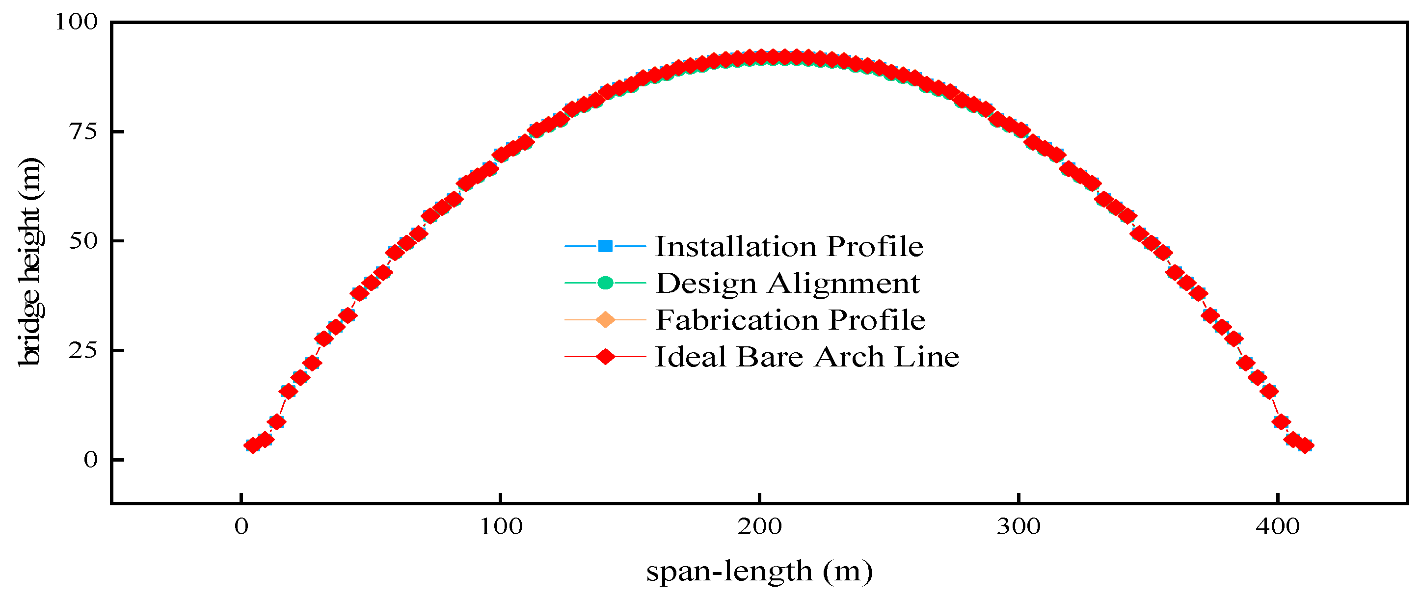
3.3. Bridge Linear Calculation

When calculating the bridge alignment, the design alignment, manufacturing alignment, ideal bare arch alignment, dead load alignment, and installation alignment are taken into account. (1) The design alignment is the alignment that needs to be achieved after the bridge is completed after sufficient time-varying (shrinkage and creep of concrete and relaxation of steel, etc.). The design alignment of the main arch of the bridge is catenary, and the arch axis coefficient is 1.54. (2) The manufacturing alignment is generally used on the basis of the design alignment. The displacement of the arch rib calculated by the reverse superposition structure is usually considered. The influence of the live load is usually considered. The bridge adopts the thrust influence line to determine the manufacturing alignment. (3) The ideal bare arch alignment is the displacement caused by self-weight under the condition of superimposing the arch ribs on the basis of manufacturing alignment. If the influence of manufacturing error and construction error is ignored, according to the principle of the non-stress state method, the internal force and alignment of the arch bridge are determined by the bare arch alignment after the closure of the arch rib construction. Therefore, the ideal bare arch alignment is the main goal of construction monitoring. (4) Based on the design alignment, the dead load alignment of the bridge is calculated by reverse superposition of the time-varying effect (concrete shrinkage and creep and steel relaxation) and vehicle live load alignment. (5) Installation alignment refers to the alignment formed by the connection of each new node during the phased construction of the bridge. It is a virtual curve. The ultimate goal of installation alignment is to achieve design alignment. The calculation results of each alignment of the bridge are shown in Figure 5.

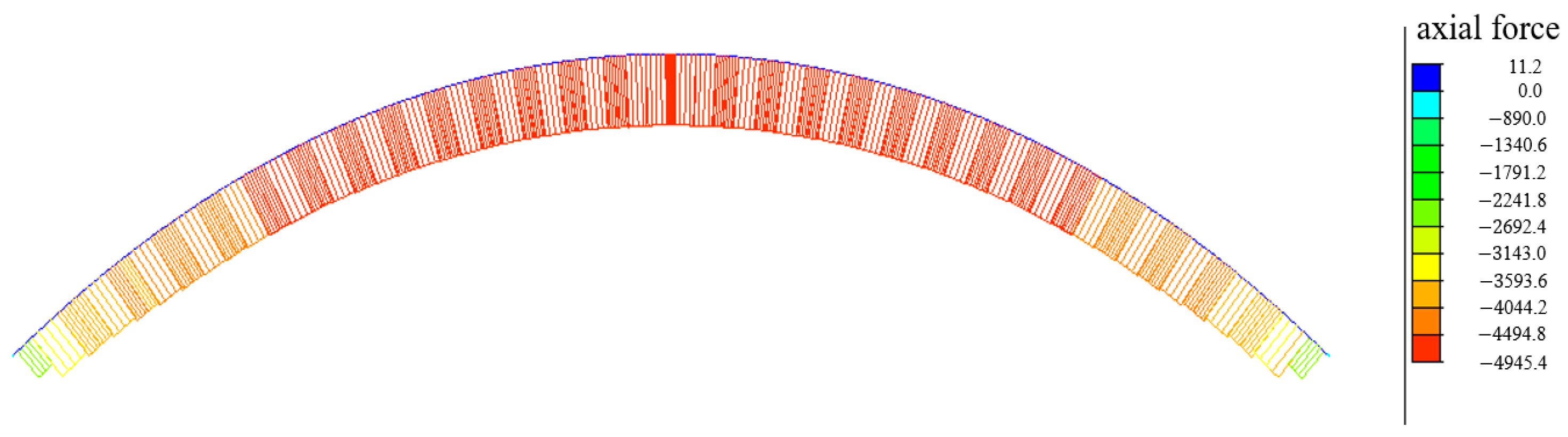
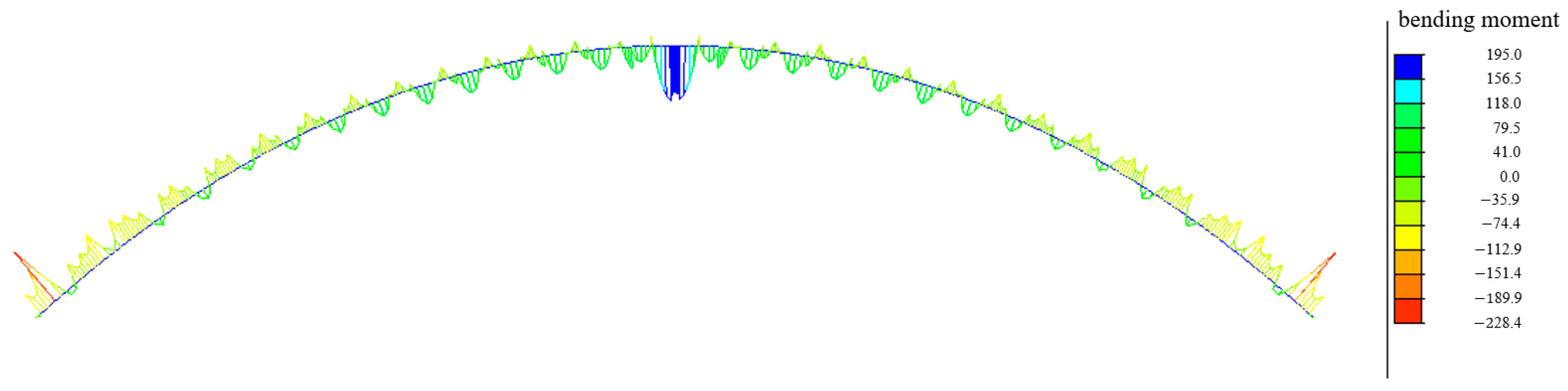
3.4. Internal Force of Bridge Arch in Bare Arch State

The bare arch alignment under one-time arching condition is the target alignment of construction monitoring, and its corresponding internal force and stress of each key section will be the target internal force and stress of construction monitoring. The axial force of the arch rib under the ideal bare arch state of the bridge is calculated, as shown in Figure 6, and the bending moment is shown in Figure 7.
It can be seen in Figure 6 that the maximum axial pressure of the arch foot in the ideal bare arch state is 2423.29 kN, and the maximum axial pressure of the vault is 4945.44 kN. In Figure 7, the bending moment in the arch conforms to the actual law of the project. The bending moment of the arch foot is −228.38 kN·m, and the bending moment of the vault is 195 kN·m. In the figure, the negative value indicates that the section is compressed, and the negative value in the following table also shows that the section is compressed.
According to the manufacturing line, the arch stress of the bridge is analyzed and calculated, and the stress of the key section of the upper and lower arch ribs is shown in Table 2. The stress of the upper and lower chord sections of the arch rib is shown in Figure 8.
It can be seen in Table 2 and Figure 8 that the arch rib section is under compression in the ideal bare arch state; this is determined by the stress characteristics of the arch. The maximum compressive stress of the arch rib appears at the arch foot of the lower arch rib, and the compressive stress is 55.1 MPa. The maximum compressive stress of the vault appears at the upper arch rib, and the stress is 39.1 MPa. The arch rib material of the bridge is Q370qc, and the strength design value is 260 MPa, indicating that the arch rib is in a safe range.

4. Analysis of Effect

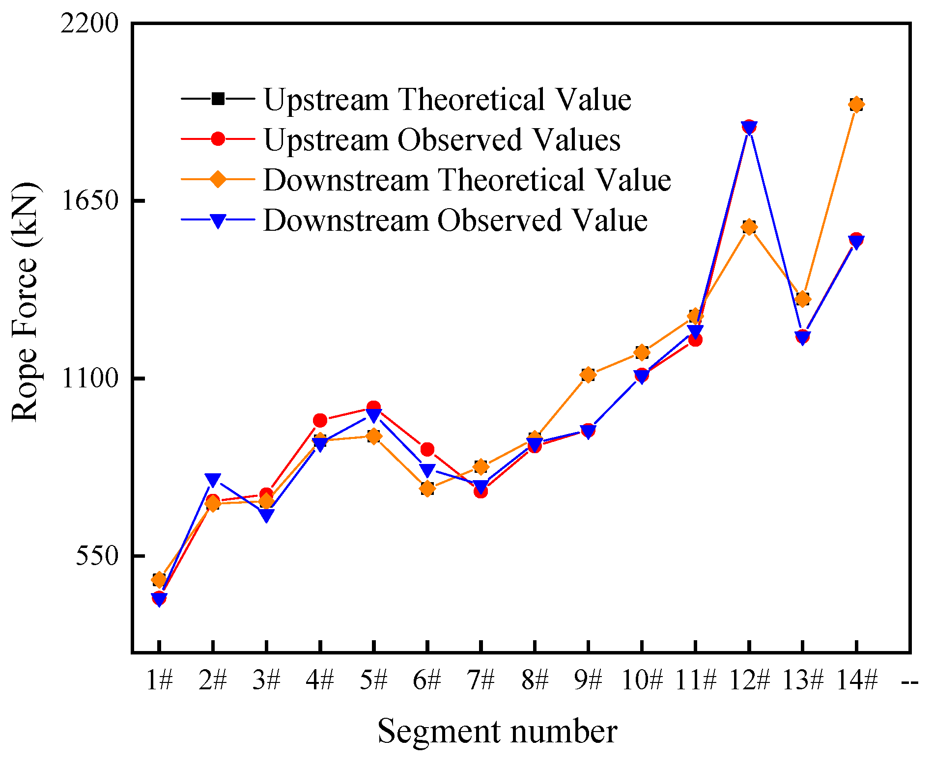
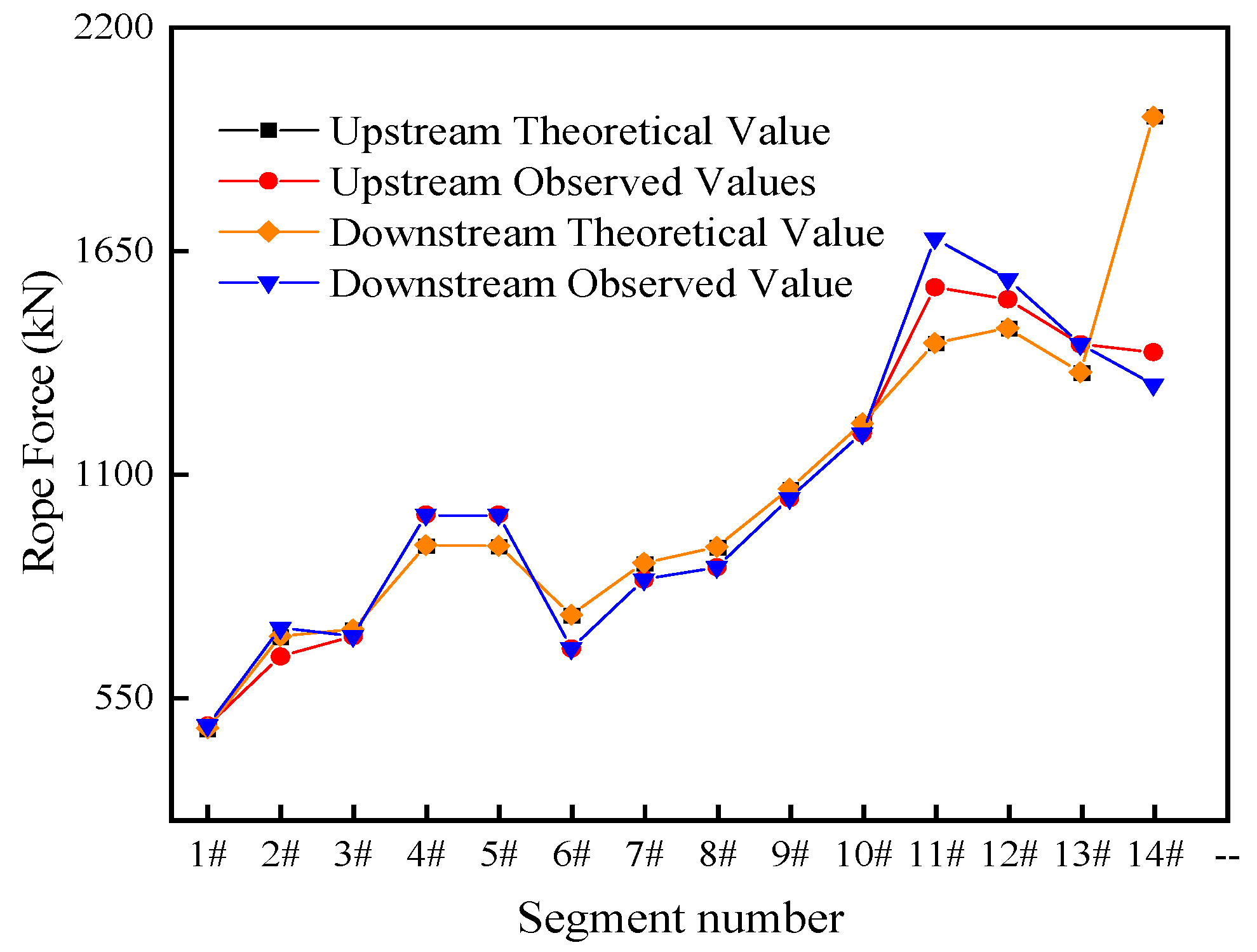
4.1. Analysis of Cable Force

The theoretical values of the cable force on the left and right sides of the arch ribs of the left bridge are calculated in Table 3 and Table 4.
It can be seen in Table 3 and Table 4 that with the cantilever construction of the bridge, the cable force of the segment increases with the increase in the number of arch rib segments. The cable force of the previous segment varies with the tension of the cable force of the arch rib of the latter segment. The overall trend is decreasing, and the tension cable force value is in line with the engineering practice.
The comparison between the actual tension value of the bridge cable force and the calculated theoretical value is shown in Figure 9 and Figure 10. Observing the two figures, it can be seen that the actual value of the cable tension is consistent with the theoretical value. From Figure 9, the error range of the theoretical value and the actual value of the cable tension in the upper and lower reaches of the 1–14 segmental arch ribs on the left bank of the bridge is −13.33–15.40%. From Figure 10, the error range of the theoretical value and the actual value of the cable tension in the upper and lower reaches of the 1–14 segmental arch ribs on the right bank of the bridge is −8.37–11.00%, which meets the engineering accuracy requirements.

4.2. Arch Rib Elevation Analysis

After tensioning the cable force, the measured and theoretical values of the tension elevation at the upstream and downstream measuring points of the 1–14 sections of the left arch rib of the arch bridge are compared with the theoretical values, as shown in Figure 11, and the elevation of the right arch rib section is shown in Figure 12. The actual elevation of the 1–14 arch rib sections is similar to the theoretical elevation after the tension cable force of the arch rib hoisting and installation. The elevation error of the left bank arch rib is −0.003–0.043 m, and the elevation error of the right bank arch rib is −0.007–0.032 m. The overall height difference error of the arch rib is low, which meets the engineering accuracy requirements. It shows that the arch shape of the bridge, after tensioning the cable force, meets the smooth requirements.
After calculating and determining the cable force, the difference between the cumulative vertical displacement of the main arch and the vertical displacement of the ideal bare arch is calculated in Table 5.
It can be seen in Table 5 that the absolute value and variation in the cumulative vertical displacement of the cable force obtained by the calculation method in the main arch suspension process are small, and the main arch alignment is smooth. The cumulative vertical displacement of the empty steel tube after arching is in the range of −0.025 to 0.027 m compared with the cumulative vertical displacement of the ideal bare arch line. It shows that the theoretical value and the actual value are basically consistent, and it meets the requirements of the “Highway Engineering Quality Inspection and Evaluation Standard” (JTG F80/1-2017) [23]. The maximum vertical deviation of arch rib closure is 0.027 m < L/3000 = 0.137 m, and the linear control precision is high, which shows that the cable force calculated by this method is feasible for controlling the construction.

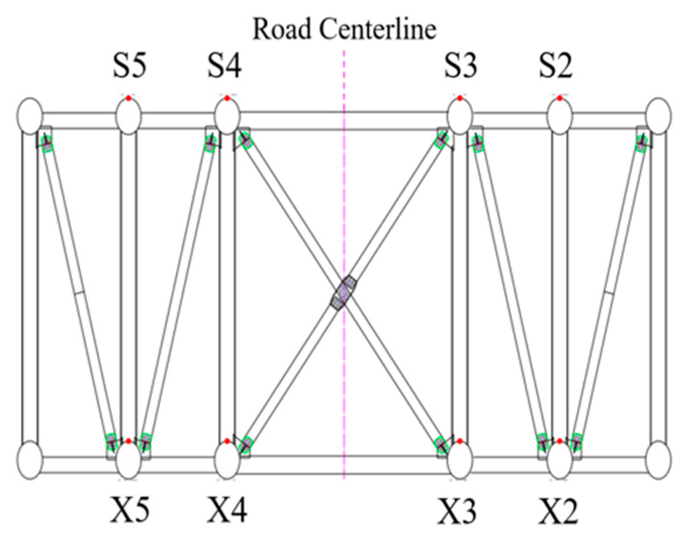
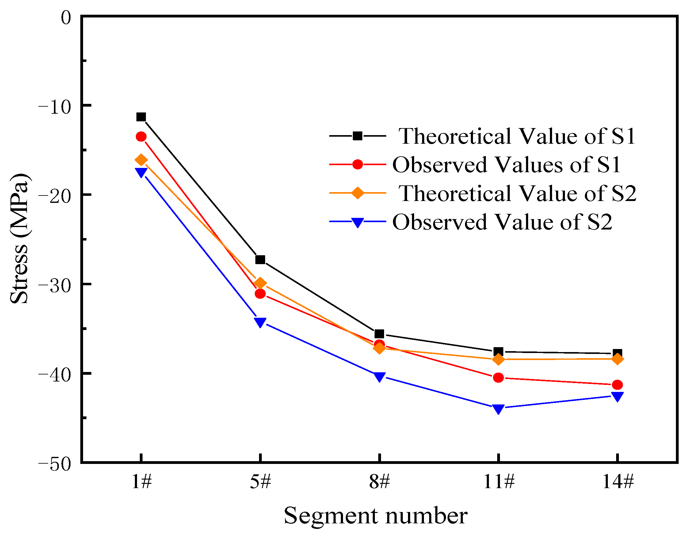
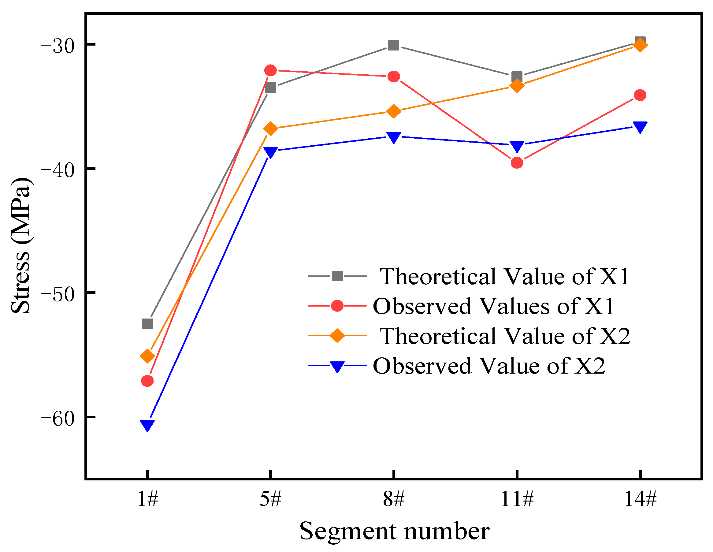
4.3. Stress Analysis of Arch Rib

To ensure the safety of arch rib construction, stress monitoring of the key section of the arch rib is carried out. The stress measuring points of the arch rib cross-section are arranged as shown in Figure 13. The stress results of the key measuring points of the arch rib are the S2 and S3 measuring points of the upper arch rib on the left bank of the bridge and the X2 and X3 measuring points of the lower arch rib. The key section position corresponding to the arch rib section is shown in Table 6.
The stress monitoring adopts the vibrating wire strain gauge, and the test results include the total strain caused by various influencing factors, such as temperature. The actual stress value can be obtained from Hooke’s law, and the expression is as follows:
σ = E ε
In the formula: ε is strain, and E is the elastic modulus of concrete, in MPa. The calculated and measured values of the stress of the upper and lower arch ribs of the key section are shown in Figure 14 and Figure 15.
In Figure 14, the difference between the measured value and the theoretical value of the arch rib stress on the steel tube is between −5.45 and −1.2 MPa. In Figure 15, the difference between the measured value and the theoretical value of the stress of the lower arch rib of the steel tube is ±7.0 MPa. The stress measurement points arranged at the key sections show that the measured stress of the steel tube arch rib is at the same level as the theoretical value, and the variation law of the measured stress is the same as the theoretical change, which meets the engineering accuracy requirements.

5. Conclusions

This paper is based on the control principle of “quiet do not move“ for the steel pipe arch ribs of the concrete-filled, steel tube arch bridge erected using the cable-stayed buckle-hang method. The forward iteration method is used to calculate the cable force, and the influence matrix method is used to calculate and adjust the cable force of the initial tension. The conclusions are as follows.
(1) Based on the principle of “quiet do not move”, the line shape is controlled, and the forward analysis method is adopted. The cable force is calculated by 1–2 iterations and then adjusted according to the influence matrix method. The tensioned cable force can make the bridge reach the ideal state.
(2) The calculation method of cable force does not involve complex calculation formulas, which makes it easy to master, and the calculation accuracy can meet the actual engineering requirements.
(3) The cable force obtained by the calculation method makes the absolute value and variation in the cumulative vertical displacement in the process of the main arch cantilever assembly smaller, the main arch alignment smooth, and the alignment control accuracy high. The application to the actual bridge shows that the method is effective and can achieve the expected requirements for arch rib installation alignment.
(4) The cable force calculated in this paper is applied to the actual engineering project, and the result is good. It is expected that the follow-up studies can find a better method for calculating the cable force of the arch bridge on the basis of this paper, providing better help to follow-up engineering projects.

Author Contributions

Formal analysis, Z.H. and Q.L.; Investigation, Y.J.; Writing—original draft, Y.J. and C.W.; Writing—review & editing, P.L. and W.L. All authors have read and agreed to the published version of the manuscript.

Funding

The National Natural Science Foundation of China No. 52068037, the Yunnan Provincial Natural Science Foundation Project No. 140520210091, the Natural Science Foundation of Fujian Province No. 2021J05239, and the Special Project on scientific research and innovation of Putian University No. 2021ZP03.

Conflicts of Interest

The authors declare no conflict of interest.

References

  1. Lai, X.Y.; Chen, B.C. A comparative analysis on two creep prediction models for CFST arch bridge. J. Fuzhou Univ. 2014, 42, 737–743. [Google Scholar]
  2. Chen, B.; Wei, J.; Zhou, J.; Liu, J.P. Application of concrete-filled steel tube arch bridges in China: Current status and prospects. China Civ. Eng. J. 2017, 50, 50–61. [Google Scholar]
  3. Gao, Y.Q.; Zhai, P.C. Construction Control of Arch Rib Hoisting of Long Span Concrete Filled Steel Tube Arch Bridge; Theory & Practice for Reform of Civil & Architecture Education Editorial Department, Wuhan University of Technology Press: Wuhan, China, 2009; pp. 92–95. [Google Scholar]
  4. Chen, B.C.; Wei, J.G.; Wu, Q.X. Design Calculation Method and Application of Concrete Filled Steel Tube Arch Bridge; China Construction Industry Press: Beijing, China, 2014. [Google Scholar]
  5. Meng, Y.S. Research on the Application of Concrete Filled Steel Tube Arch Bridge Construction Technology. Constr. Des. Eng. 2022, 16, 197–199. [Google Scholar]
  6. Xu, F. Installation construction technology of steel pipe arch of Wumei River Bridge. Highway 2022, 67, 221–225. [Google Scholar]
  7. Zhang, Z.C.; Ye, G.R.; Wang, Y.F. Optimization of stayed-buckle cable forces during adjustment of the line-shape on long span arch bridge. Eng. Mech. 2004, 6, 187–192. [Google Scholar]
  8. Liu, S.P.; Zhang, M.; Duan, Y.S. Cable force calculation of Daninghe bridge based on Zero-order optimization method. J. Munic. Technol. 2009, 27, 354–356+364. [Google Scholar]
  9. Zhou, Y.; Wang, Y.; Zhou, J.T.; Huang, Z.; Zhang, X.; Xiang, Z. Arch forming calculation theory and control method of 500 m steel tube arch bridge. China J. Highw. Transp. 2022, 35, 60–72. [Google Scholar]
  10. Gu, Y.; Yao, C.R.; Li, Y.D.; Kang, L. Study of alignment control method for installation of arch ribs of long span CFST arch bridge. Bridge Constr. 2014, 44, 107–113. [Google Scholar]
  11. Ye, L.X.; Ke, H.J.; Chen, Z. Analysis of assembly stage of suspension bridge with steel box girder anchor based on Midas Civil. J. China Foreign Highw. 2020, 40, 140–145. [Google Scholar]
  12. Zhang, L. Long-Span Cable-Stayed Bridge Deck Linear Adjustment Technology Research. Ph.D. Thesis, Chongqing Jiaotong University, Chongqing, China, 2015. [Google Scholar]
  13. Hu, D.L.; Chen, D.S.; Zhao, X.Y.; Gong, J.P.; Li, Y. Construction control of cantilever casting of long span reinforced concrete arch bridge. J. Traffic Transp. Eng. 2016, 16, 25–36. [Google Scholar]
  14. Chen, D.L.; Miao, L.; Tian, Z.C.; Luo, Z.L. Calculation of the cable-stayed force and pre-camer in the process of assembling arch bridge segments. Eng. Mech. 2007, 5, 132–137. [Google Scholar]
  15. Wang, Q.A.; Dai, Y.; Ma, Z.G.; Ni, Y.Q.; Tang, J.Q.; Xu, X.Q.; Wu, Z.Y. Towards probabilistic data-driven damage detection in SHM using sparse Bayesian learning scheme. Struct. Control. Health Monit. 2022, 29, e3070. [Google Scholar] [CrossRef]
  16. Wang, Q.A.; Wang, C.B.; Ma, Z.G.; Chen, W.; Ni, Y.Q.; Wang, C.F.; Yan, B.G.; Guan, P.X. Bayesian dynamic linear model framework for SHM data forecasting and missing data imputation during typhoon events. Struct. Health Monit. Int. J. 2022, 21, 2933–2950. [Google Scholar] [CrossRef]
  17. Wang, Q.A.; Zhang, C.; Ma, Z.G.; Ni, Y.Q. Modelling and forecasting of SHM strain measurement for a large-scale suspension bridge during typhoon events using variational heteroscedasic Gaussian process. Eng. Struct. 2021, 251, 113554. [Google Scholar]
  18. Wang, Q.A.; Zhang, C.; Ma, Z.G.; Jiao, G.Y.; Jiang, X.W.; Ni, Y.Q.; Wang, Y.-C.; Du, Y.T.; Qu, G.B.; Huang, J. Towards long-transmission-distance and semi-active wireless strain sensing enabled by dual-interrogation-mode RFID technology. Struct. Control. Health Monit. 2022, 29, e3069. [Google Scholar] [CrossRef]
  19. Wang, Q.A.; Dai, Y.; Ma, Z.G.; Wang, J.F.; Lin, J.F.; Ni, Y.Q.; Ren, W.X.; Jiang, J.; Yang, X.; Yan, J.R. Towards high-precision data modeling of SHM measurements using an improved sparse Bayesian learning scheme with strong generalization ability. Struct. Health Monit. Int. J. 2023; online. [Google Scholar] [CrossRef]
  20. Zhu, L.W.; Deng, N.C.; Yu, M.S.; Guo, X. Research on formal iterative optimization algorithm for buckle cable force in 600 m class arch bridge construction by cable-stayed buckling method. Railw. Eng. 2020, 60, 18–21. [Google Scholar]
  21. He, B.T. Calculation of initial cable force of suspender of concrete filled steel tube arch bridge based on forward iteration method. Highw. Automot. Appl. 2022, 3, 110–111+134. [Google Scholar]
  22. Gao, J.; Chen, L.Y.; Wang, J.W. Optimization of tension force for hangers in multi-span tied-arch bridge based on influence matrix method. Highway 2022, 67, 165–170. [Google Scholar]
  23. JTGF80/1-2017; Meng, S.T. Inspection and Evaluation Quality Standards for Highway Engineering Section 1 Civil Engineering. Ministry of Transport of China: Beijing, China, 2018.
Figure 1. Cable force calculation process.
Buildings 13 02370 g001
Figure 2. General plan of the bridge.
Buildings 13 02370 g002
Figure 3. Arch rib section diagram.
Buildings 13 02370 g003
Figure 4. Bridge calculation model.
Buildings 13 02370 g004
Figure 5. Bridge linear calculation results.
Buildings 13 02370 g005
Figure 6. The axial force diagram (kN).
Buildings 13 02370 g006
Figure 7. The bending moment diagram (kN·m).
Buildings 13 02370 g007
Figure 8. Sectional stress of upper and lower chords of arch rib.
Buildings 13 02370 g008
Figure 9. Left bank cable force.
Buildings 13 02370 g009
Figure 10. Right bank cable force.
Buildings 13 02370 g010
Figure 11. Segment elevation after left bank cable tension.
Buildings 13 02370 g011
Figure 12. Segment elevation after right bank cable tension.
Buildings 13 02370 g012
Figure 13. Stress measuring point arrangement.
Buildings 13 02370 g013
Figure 14. Upper arch rib stress.
Buildings 13 02370 g014
Figure 15. Stress of lower arch rib.
Buildings 13 02370 g015
Table 1. Calculation condition division of the construction stage.
Working ConditionConstruction StateWorking ConditionConstruction State
1Juncture pier22Tension buckle anchor cable KS8
2Segment 1 + buckle anchor cable KS123Support MC5
3Pouring arch foot oblique web member and hinge shaft concrete24Arch foot sealing
4Arch foot K brace KC225Segment 9
5Segment 226Tension buckle anchor cable KS9
6Tension buckle anchor cable KS227Segment 10
7Support MC128Tension buckle anchor cable KS10
8Segment 329Support MC6
9Tension buckle anchor cable KS330Segment 11
10Support MC231Tension buckle anchor cable KS11
11Segment 432Segment 12
12Tension buckle anchor cable KS433Tension buckle anchor cable KS12
13Support MC334Support MC7
14Segment 535Segment 13
15Tension buckle anchor cable KS536Tension buckle anchor cable KS13
16Segment 637Segment 14
17Tension buckle anchor cable KS638Tension buckle anchor cable KS14
18Support MC439Support MC8
19Segment 740Arch top K brace KC1
20Tension buckle anchor cable KS741closure segment
21Segment 842Disconnecting anchor cable
Table 2. Key section stress sheet.
Construction StagePositionUpper Arch Rib/MPaLower Arch Rib/MPa
Bare arch statearch abutment−16.1−55.1
L/8−29.9−36.8
L/4−37.2−35.35
3 L/8−38.45−33.35
arch vault−39.1−31.2
Note: “L” in the table is the bridge span.
Table 3. Statistical table of cable force calculation in the construction stage of the left bank (unit: kN).
Segment NumberKS1KS2KS3KS4KS5KS6KS7KS8KS9KS10KS11KS12KS13KS14
1#473.0
2#467.8735.3
3#467.3731.3740.5
4#470.8737.8746.6867.2
5#478.6755.2767.3887.8877.8
6#488.8779.7797.0922.3909.7683.1
7#497.1799.5822.4953.0939.5718.0799.6
8#501.1808.8835.9971.8960.3745.3827.3798.8
9#506.4817.6846.2984.7974.1764.2846.9817.21066.6
10#503.7808.8837.3977.9971.6766.6853.6826.71077.31083.7
11#500.0794.8820.9961.3959.5758.2850.4827.81081.11090.41336.3
12#497.4777.1803.5939.3939.5745.1841.5823.31080.31093.01340.91428.4
13#492.3751.4771.4900.1903.4711.0813.8802.61066.11080.41332.81421.91218.9
14#484.8711.6717.3831.0836.1638.6748.6747.01020.31029.01289.11379.51188.51729.4
closure segment482.8708.9712.0828.9838.2641.6756.2758.31034.61052.11315.91412.71216.21761.8
Table 4. Statistical table of cable force calculation in the right bank construction stage (unit: kN).
Segment NumberKS1KS2KS3KS4KS5KS6KS7KS8KS9KS10KS11KS12KS13KS14
1#471.6
2#465.4745.7
3#462.6736.2751.7
4#467.9746.6762.3873.3
5#476.3764.8783.3891.8918.9
6#486.7788.7814.1923.3947.7698.1
7#496.1810.3841.9953.0976.0731.0815.1
8#501.2821.8857.6971.9996.4756.5840.8814.9
9#508.5834.0871.0986.11010.7774.8859.3832.11097.1
10#506.2825.5863.1980.81009.1777.8866.0841.11107.01109.7
11#502.5811.1845.8965.2997.7769.0862.0841.01109.41114.81381.5
12#500.5793.8829.5946.3980.4757.7854.4837.31109.11117.81386.31463.2
13#496.3767.8799.2912.0948.4728.7830.8819.81097.11106.31379.11457.51246.8
14#488.7726.3742.9847.5885.9661.1770.2768.21054.71053.51334.01413.51219.31767.1
closure segment486.1723.5736.2845.1887.8662.8776.4778.01067.41076.31360.51446.41243.01799.0
Table 5. Comparison of cumulative vertical displacement of each arch section.
Segment NumberThe Hollow Steel Pipe Falls Once/mBuckle/mDifference/m
1#−0.004−0.0090.005
2#−0.009−0.0140.004
3#−0.017−0.0190.002
4#−0.025−0.023−0.002
5#−0.034−0.026−0.007
6#−0.043−0.031−0.013
7#−0.053−0.035−0.018
8#−0.062−0.04−0.022
9#−0.071−0.046−0.025
10#−0.078−0.053−0.025
11#−0.084−0.063−0.021
12#−0.09−0.077−0.013
13#−0.095−0.0950.001
14#−0.098−0.1240.027
Table 6. Corresponding table of key sections and arch rib segments.
Key SectionsRib Segment
arch feet1#
L/85#
L/48#
3 L/811#
arch roof14#
Disclaimer/Publisher’s Note: The statements, opinions and data contained in all publications are solely those of the individual author(s) and contributor(s) and not of MDPI and/or the editor(s). MDPI and/or the editor(s) disclaim responsibility for any injury to people or property resulting from any ideas, methods, instructions or products referred to in the content.

