Article

Formation of Cellular Concrete Structures Based on Waste Glass and Liquid Glass

by
Svetlana V. Samchenko
and
Andrey V. Korshunov
*
Department of Building Materials, Moscow State University of Civil Engineering, 26, Yaroslavskoye Shosse, 129337 Moscow, Russia
*
Author to whom correspondence should be addressed.
Buildings 2024, 14(1), 17; https://doi.org/10.3390/buildings14010017
Submission received: 23 October 2023 / Revised: 7 December 2023 / Accepted: 18 December 2023 / Published: 20 December 2023
(This article belongs to the Special Issue Advances in Sustainable Building Materials)

Abstract

:
The use of waste in the production of building materials is one of the possible ways to solve problems related to the sustainable management of non-degradable waste and difficult-to-recycle secondary resources. In this paper, a method is proposed for the non-autoclave production of an ultra-lightweight cellular concrete based on Portland cement, glass waste and liquid glass. A mixture of sodium hexafluorosilicate and hydroxide is used as a hardening activator, an aluminum powder serves as a gas-forming agent. The setting and hardening of raw mixtures occurs under the action of exothermal heat release due to a complex of chemical reactions occurring in the system, and the resulting material does not require additional heat treatment. It is optimal to use two fractions of glass waste to achieve acceptable material strength: coarse crushed (fineness modulus Fm = 0.945) and finely ground (specific surface Ssp = 450–550 m2/kg) glass. Glass particles of the fine fraction of glass, along with Portland cement, participate in hydrolytic and structure-forming processes, while glass particles of the coarse fraction play the role of reinforcing filler. The influence of the dispersion of glass and the density of liquid glass on the density, porosity, strength, water absorption and water resistance of the resulting cellular material was determined. At an average density of cellular concrete in the dry state of 150–320 kg/m3, the following characteristics can be achieved: a compressive strength up to 2.0 MPa, bending strength up to 0.38 MPa, thermal conductivity coefficient of the material in the range 0.05–0.09 W/(K·m), and a maximum operating temperature of 800 °C. The proposed ultra-lightweight cellular concrete can be used as a non-combustible heat and sound insulation material, as well as a repairing composition; the cellular concrete blocks can be used as filling masonry and for the construction of non-bearing internal walls.

1. Introduction

Currently, much attention is paid to the reasonable and integrated use of secondary raw materials in the production of building materials and products due to the need to save and use natural resources efficiently [1]. The development of low-waste and non-waste technologies as well as the utilization of waste make it possible to improve the environmental situation and to decrease the loss of non-renewable raw materials [2]. Glass waste is a large-tonnage secondary mineral raw material which is quite difficult to recycle [3]. The disposal of glass waste has a negative impact on the environment, as landfilled glass does not allow for soil recultivation [3]. In this regard, the search for new ways of glass waste usage is an important task.
One of the ways of practical use of glass waste is the production of building materials with as an aggregate [3]. Crushed glass can be used for the production of the following materials: foamed glass [4], ceramic products for industrial buildings and interiors, ceramics for facade facing and thermal insulation [5,6,7], cement-based materials [8,9,10,11,12,13,14,15,16] and geopolymer concretes [17,18,19]. Cullet is also used for road construction as part of asphalt concrete [20] or so-called glassphalt [21], for the production of road and sidewalk coverings [22], to produce glass beads that provide retroreflectivity to road markings [23].
A promising direction for the use of cullet is the production of porous heat-insulating materials and foamed concrete [24,25,26,27]. Heat insulators [28] based on foamed polyurethane, polypropylene, polystyrene, etc., are combustible [29,30], and their use for the construction of residential buildings and technological structures carries certain risks in terms of fire and chemical hazards. The fibrous heat-insulating mineral materials (mineral and glass wool) do not provide full protection of metal structures against corrosion, as such constructions require additional waterproofing [31]. Porous heat-insulating cement-containing materials, as well as concretes with artificial porous aggregates are less effective than polymers, because their thermal conductivity coefficient reaches 0.7 W/K·m [32,33], and the required thickness of the heat-insulating layer and the total weight of the product become significant.
One of the directions of obtaining porous materials using glass waste is the use of alkaline-activating reagents under hydrothermal treatment conditions [34,35]. A significant decrease in temperature during the production of porous materials is achieved by using liquid glass as a hardener for slag-based mixtures [36,37,38]. The hardening of mixtures based on liquid glass occurs at elevated temperatures [39], together with a change in the pH of the medium, or during exposure of solid hardeners. An analysis of the literature has shown that the processes of obtaining, as well as properties of porous materials based on waste glass and on liquid glass have not been fully studied. In this regard, the purpose of this work was to determine the conditions for the formation of the porous structure of cellular concrete based on waste glass and on liquid glass.

2. Materials and Methods

2.1. Materials

The following materials were used as raw materials for the production of aerated concrete: cullet, liquid glass, sodium hydroxide, sodium hexafluorosilicate, Portland cement, and water. Aluminum powder was used as a gas-forming agent. Chemical reagents were of a ‘chemical purity’ grade and were used without additional purification.
Glass wastes: unsorted cullet was used in the work with a fineness modulus Fm = 0.945, a true density of 2435 kg/m3, and a bulk density of 1313 kg/m3. Part of the cullet was ground to powder to achieve a specific surface of 450–550 m2/kg. The grinding of glass was carried out using a laboratory planetary ball mill XQM-4A (China) with a capacity of 4 L at a rotation speed of 70 rpm using steel balls. The grinding time to reach a specific surface area of ground glass of 450–550 m2/kg was 40–60 min. The average chemical composition of the used glass waste is presented in Table 1.
Liquid glass: sodium liquid glass was used in the work, which is an alkaline aqueous solution of sodium silicates Na2nSiO2 with a mass fraction of SiO2 22.7–29.6 wt.%, silicate modulus n = 2.3–2.6 and density of 1360–1450 kg/m3.
Aluminum powder: aluminum powder of the PAP-1 brand was used as a gas-forming agent for the formation of a porous structure of glass-filled concrete. The residue on the sieve No. 008 is 1%. The powder contains impurities, wt.%: iron 0.5, silicon 0.4, copper 0.05, manganese 0.1, moisture 0.2, oil 3.8.
Sodium hexafluorosilicate, Na2SiF6, was used as an accelerator of gas formation and a hardener. The reagent purity: 98 wt.% of Na2SiF6, insoluble residue is not larger than 1 wt.%, water is not more than 0.5 wt.%.
Sodium hydroxide: sodium hydroxide NaOH used in the work contained at least 99% NaOH, the mass fraction of sodium carbonate (Na2CO3) did not exceed 0.8 wt.%.
Portland cement: to ensure the strength and increased water resistance of the pore walls in a porous material, Portland cement CEM I 42.5 R (EN 197–1) containing tricalcium silicate in an amount of at least 60 wt.%, and tricalcium aluminate no more than 9 wt.%; the specific surface area of cement was 300–400 m2/kg.
Water: distilled water was used to prepare mixtures of components.

2.2. Research Methods

The initial components and the resulting porous materials were studied using the following methods.
Mechanical testing of samples: tests of air-cured samples of cellular glass-filled concrete for compressive and bending strength were carried out in accordance with European standards [40,41]. Samples for measuring compressive strength of cubic shape with 10 cm side and for measuring bending strength of a beam shape 10 × 10 × 36 cm3 were cut from control blocks with dimensions of 20 × 40 × 40 cm3. The control blocks were obtained by pouring molds of appropriate sizes by approximately 1/3 volume with a thoroughly stirred mixture of components, holding the mixture until the end of the foaming process, and then unmolding the blocks after 3 days of storage at 20 ± 2 °C. Further, the blocks were wrapped with polyethylene film and stored under similar conditions for 28 days. Before the tests, the sawn samples were dried in a drying cabinet at 60 °C to a constant weight. Compressive and bending strength tests were carried out using CONTROLS MCC8 50-C8422 (Controls s.r.l., Milan, Italy) and PM–A-70AB (Metropress, Moscow, Russia) presses, respectively; the loading rate was 0.05 kN/s. The tests of samples of the same composition were repeated six times, the average strength values were calculated based on the results obtained.
Specific surface area (Ssp): determination of the specific surface area of materials with developed microstructure and porosity was carried out using the Brunauer-Emmett-Teller (BET) method using the Quantachrome NOVA 2200e (Quantachrome Instruments, Boyton Beach, FL, USA) device. According to the experimental data of low-temperature nitrogen adsorption at 77 K, adsorption isotherms were plotted. Using the Pierce method integral and differential curves of volume and surface of mesopores distribution by size were plotted as well as and the total volume and surface of mesopores were determined. The molar volume of nitrogen was assumed to be 34.6 × 10⁻⁶ m3/mol, and the surface tension 8.72 mJ/m2. To calculate the dependence t = f(P/Ps), the Harkins–Jura equation was used.
Particle size distribution: the particle size distribution was determined using an Analysette 22 NanoTec device (Fritsch GmbH, Idar-Oberstein, Germany).
Thermal analysis: differential thermal analysis (DTA) and thermogravimetric analysis (TG) were used to study the thermal transformations that occur when materials are heated. The STA 449 F5 Jupiter (NETZSCH-Geratebau GmbH, Selb, Germany) was used as a thermal analyzer. The samples were heated in open corundum crucibles in an air medium with a purge rate of 100 mL/min and with a heating rate of 10 K/min.
X-ray phase analysis: XRD patterns were obtained using a SHIMADZU XRD 6000 diffractometer (Shimadzu Corp., Kyoto, Japan) with a Cu-anode (λKa1 = 1.54056 Å; 40 mA and 40 kV). X-ray diffractograms were taken at a 5–70° range of 2θ with a scanning step 0.02°.
Porosity of samples: the porosity of the samples was determined by the experimental calculation method, which consists of using the experimentally determined values of the true density of the material and its average density ρ0 in the dry state. Porosity P (%) was calculated using the formula
P = 1 ρ 0 ρ 100 %
The open porosity of Pop (%) was determined by the formula
Pop = Wo,
where Wo is the water absorption of the material by volume, %.
The closed porosity of Pc (%) was calculated by the formula:
Pc = PPop.
The apparent density of the samples was determined by the formula:
ρ = m V
where m is the mass of the dried sample, kg;
  • V is the volume of the product, m3.
To calculate the true density, an AccuPyc II 1340 (Micromeritics Instrument Corporation, Norcross, GA, USA) automatic helium pycnometer was used.
Electron microscopy: a multifunctional scanning electron microscope JCM-6000 PLUS (JEOL Ltd., Tokyo, Japan) was used to study the structure. The elemental composition of the samples was determined using X-ray spectral microanalysis on a Phenom ProX (ThermoFisher Scientific, Waltham, MA, USA) microscope with a backscattered electron detector.
Infrared spectroscopy: the chemical composition of the samples was studied using IR spectroscopy (Nicolet iS50, ThermoFisher Scientific, Waltham, MA, USA). IR spectra were obtained in KBr pellets in the spectral range of 4000–400 cm−1.
Thermal conductivity: to measure the thermal conductivity and to determine the thermal resistance of the obtained porous materials, the ITP-MG4 (Stroypribor, Chelyabinsk, Russia) thermal conductivity meter was used.

3. Results and Discussion

The technology of producing aerated concrete containing cullet is usually based on the use of autoclave treatment [26]. The key process in the autoclave treatment of mixtures with glass powder containing at least 15% of alkaline oxides is the formation of insoluble silicates. In the present work, in order to increase the energy efficiency of the process, liquid glass was used instead of autoclave treatment of the aerated concrete mixture. Since the liquid glass used in the work is high modulus (n = 2.3–2.6) with increased viscosity, it is necessary to introduce water into the composition, which helps to increase the porosity of the resulting material. In addition, an important factor determining the properties of the resulting aerated concrete is the dispersion of glass.

3.1. Composition, Morphology and Dispersion of Technical Glass Waste

In this work, unsorted cullet was used, which is rarely used by glass factories, since it negatively affects the homogeneity of the glass mass during the melting of the batch and the quality of the glass products. When preparing a raw material mixture to produce a non-combustible cement-containing porous material, the uniformity of the glass mass is not a critical indicator, therefore, it is possible to use cullet with different chemical composition and different dispersion. Before mixing the components of the raw mixture, cullet was degreased in acetone, then washed in distilled water and dried at room temperature. Further, the cullet was milled in a screw crusher until the following characteristics were obtained: fineness modulus Fm = 0.945; true density 2435 kg/m3; bulk density 1313 kg/m3. To achieve an optimal packing density of the raw mixture grains and the formation of a dense and durable structure, the proportion of large and small fractions of ground glass should be approximately equal. Finely milled cullet is a structure-forming material due to the interaction of amorphous silicon dioxide SiO2 contained in the cullet with the alkaline medium of liquid glass and Portland cement. The strength of the pore walls in the thermal insulation material depends on it. In this regard, to increase the fine fraction quantity, a part of the crushed glass was milled to powder in a ball mill until a Ssp of 450–550 m2/kg was reached. The fractional composition of crushed and ground cullet is shown in Table 2. The distribution functions of milled glass particles by size are shown in Figure 1.
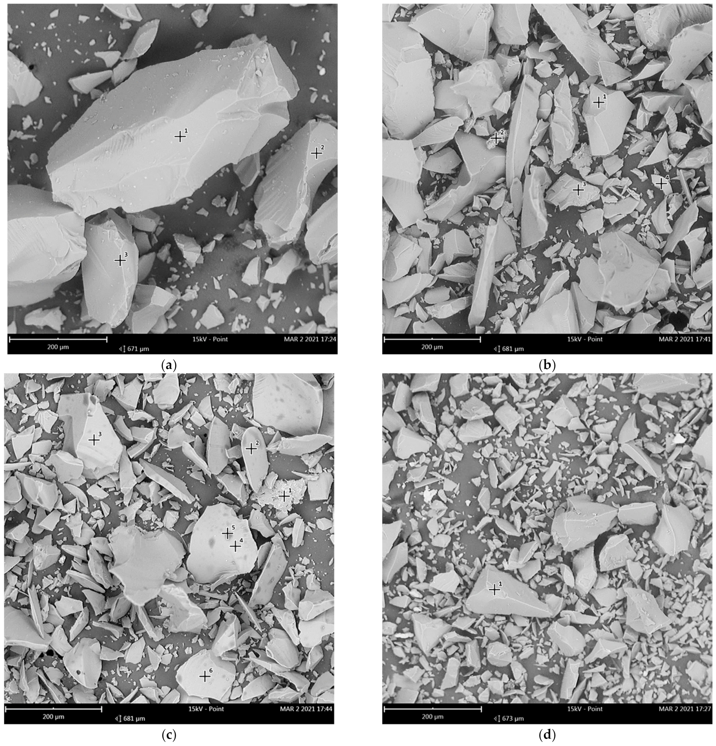
Electron microscopy studies of cullet particles have shown that the particles have, as a rule, an unequal fragmentation shape (Figure 2). Based on the results of the dispersion scattering of light, the size characteristics of glass samples were determined: volume D43, surface D32 and arithmetic D10 equivalent particle diameters. Crushed glass with Ssp = 450 m2/kg was used as a reference sample (Table 3).
The fractional composition analysis of the glass samples shows that the ratio of the volume mean D43 of glass particles with Ssp = 500 m2/kg is 2.05-fold smaller, and the ratio of the arithmetic mean size D10 is 1.27-fold smaller compared to the reference sample. The ratio of the volume mean D43 of cullet particles with Ssp = 550 m2/kg to the reference sample is 2.09-fold less, and the ratio of the arithmetic mean size D10 is 1.33-fold less. The increase in the D43 of the sample with Ssp = 550 m2/kg in relation to the particles with Ssp = 500 m2/kg is 1.9%, and the arithmetic mean size D10 is reduced by 4.7%. The Ssp of the particles also does not change significantly, it is increased by 3.2%. Consequently, further grinding is impractical, since with an increase in the duration of grinding, the energy consumption of this process increases significantly.

3.2. Mechanisms of the Structure Formation of Cellular Concrete Based on Waste Glass and Liquid Glass

In preliminary experiments [42,43], it was found that the formation of cellular concrete with acceptable strength characteristics under air cured conditions is achieved at the following ratios of raw components: liquid glass 28–32 wt.% (ρ = 1230–1350 kg/m3), polydisperse cullet 38–47 wt.%, Portland cement 9–12 wt.%, sodium hexafluorosilicate 3.5–4.5 wt.%, sodium hydroxide 2.5–3.5 wt.%, aluminum powder 1–1.2 wt.%, water 8–9 wt.%. When preparing the cement paste, liquid glass and water were added to the thoroughly mixed solid components. After obtaining the homogeneous paste, the mixture is spontaneously warming up to 80–100 °C due to exothermal reactions (hydration, reaction of aluminum with alkali). Further formation of a porous structure and hardening of the material occurred in 20–40 min. After hardening and cooling, the resulting material does not require additional heat treatment. An increase in the proportion of Portland cement and alkali results in too rapid setting of the mixture; a change in the ratio of liquid glass to cullet has a negative effect on the strength characteristics of the resulting cellular material; an increase in the proportion of aluminum leads to an increase in the heterogeneity of the porous structure. Further, a more detailed study of the influence of the most significant factors on the structure and strength of the resulting aerated concrete was carried out.

3.2.1. The Effect of the Dispersion of Glass Particles on the Strength of Glass-Filled Cellular Concrete

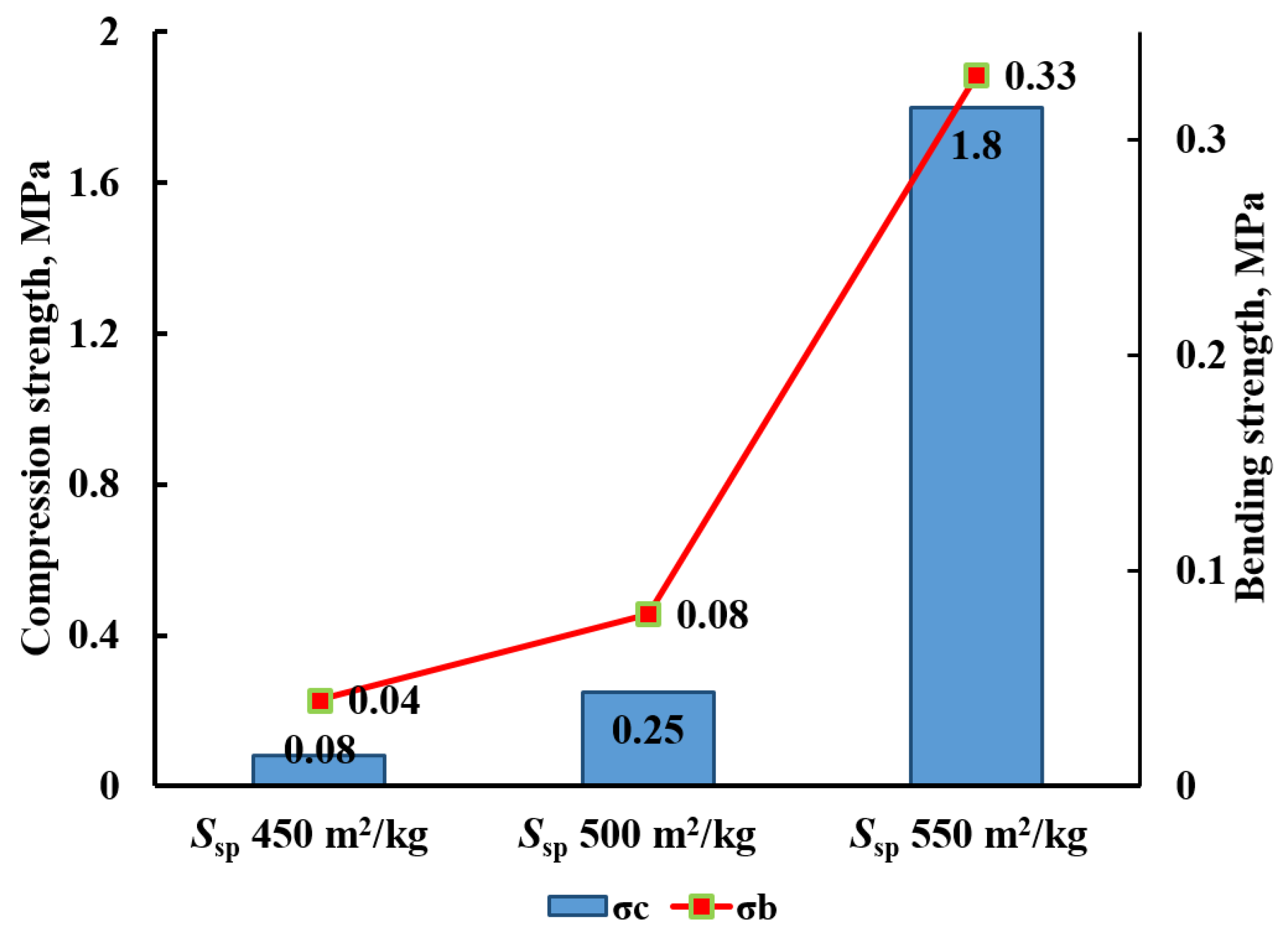
The effect of the Ssp of glass waste on the strength characteristics of cellular concrete was studied on the samples containing glass particles with a variable dispersion of 40 wt.%, liquid glass of 30 wt.% (ρ = 1300 kg/m3), Portland cement of 12 wt.%, sodium hexafluorosilicate of 4.3 wt.%, sodium hydroxide of 3.5 wt.%, aluminum powder of 1.2 wt.%, and water of 9 wt.%. The samples were not subjected to additional processing and were stored at normal temperature. The results of measuring the strength of cellular concrete samples are shown in Figure 3.
With an increase in the specific surface area, the strength of cellular concrete during compression and bending increases significantly: acceptable strength is provided by the addition of milled glass with a specific surface area of 450–550 m2/kg, and a further increase in strength is observed for samples with milled glass with a specific surface area of 500–550 m2/kg (Figure 3). Apparently, the observed dependence of strength on dispersion is due to the greater reactivity of small glass particles, contributing to the formation of polymer silicate structures under the action of an alkaline medium.
The importance of the colloidal stage and the formation of insoluble stabilizing polysilicate structures has been shown by XRD and IR spectral studies. The IR spectra of cellular concrete based on liquid glass and cullet (Figure 4) are characterized by narrowing of the absorption bands of symmetric (vs) and antisymmetric (vas) vibrations of Si–O–Si and O–Si–O–bonds, as well as the appearance of an intense band at 1120 cm−1 related to a distorted chain [(SiO3)2] in a three-dimensional cell. These characteristics indicate the ordering of the structure due to the crystallization of silicates with the formation of silica carcass. Consequently, the hardening of cellular concrete is associated with the formation of a rigid and durable three-dimensional silicon-oxygen tetrahedral lattice due to the tetrahedral polymerization. At the same time, particles of a larger fraction of crushed glass act as a reinforcing filler.
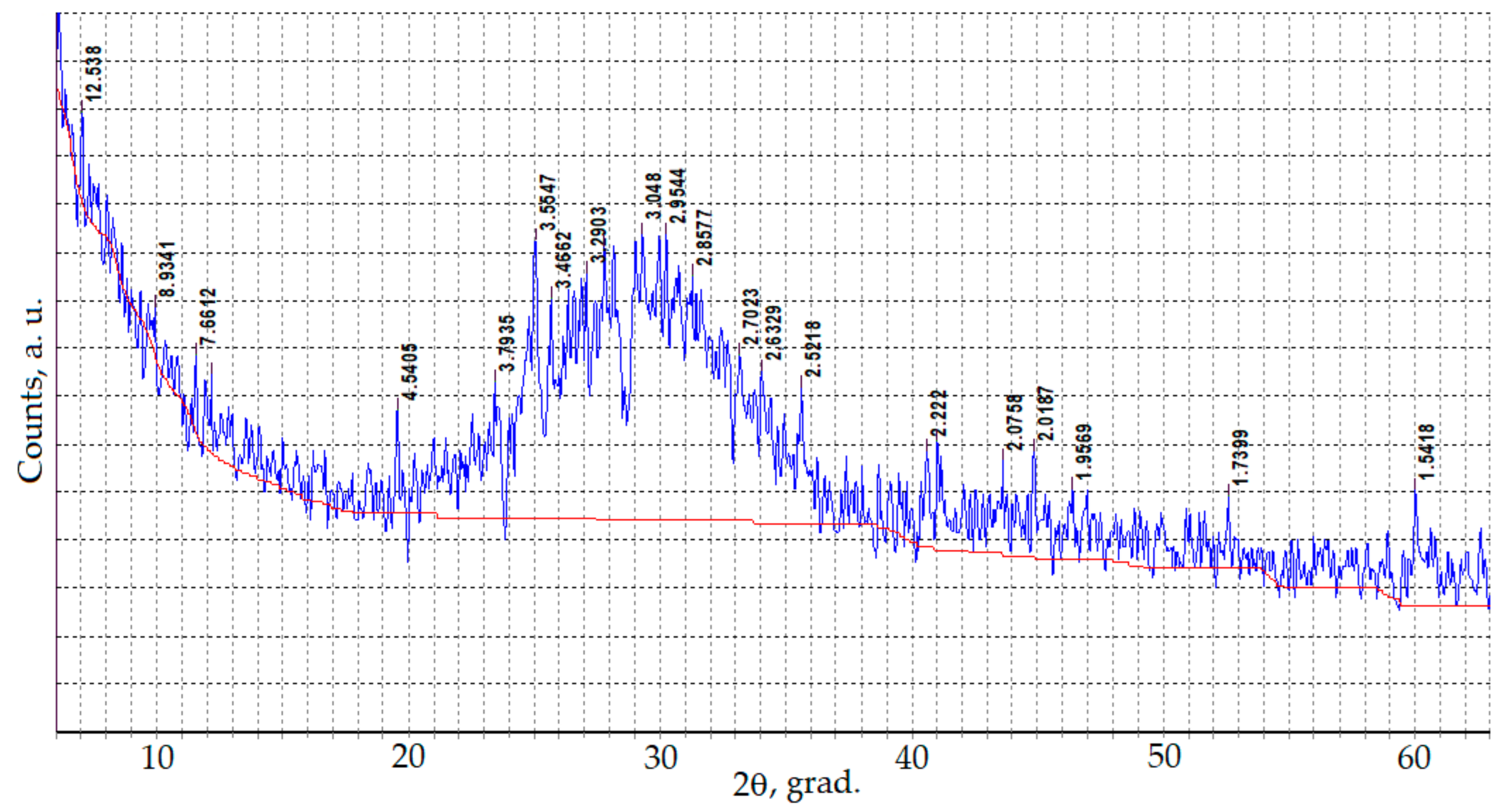
The formation of crystalline structures in the cell walls in cellular concrete is provided by the XRD analysis. The X-ray diffraction patterns shows a wide halo in the area of calcium-sodium hydrosilicates and quartz (Figure 5).
The hydration products formation in glass-filled concrete with liquid glass can be described by the following chemical reactions:
  • Polycondensation of silicic acid:
    nSi(OH)4 → (OH)3SiO(Si(OH)2)n–2OSi(OH)3 + (n − 1)H2O;
  • Formation of hydrosilicates during cement hydration:
    C3S + H2O → (0.8–1.0)CaO·SiO2·(1.0–1.5)H2O + 2Ca(OH)2;
  • Formation of double silicates and silica gel:
    Na2O·2SiO2 + mH2O + Ca(OH)2 → Na2O·CaO·SiO2·nH2O + SiO2 + (mn)H2O.
Sodium hexafluorosilicate (Na2SiF6) interacts with alkali and releases silicic acid during hydrolysis, which hardens and strengthens the pore walls of aerated concrete:
SiF62− + 4OH → Si(OH)4 + 6F
Pore formation in glass-filled cellular concrete occurs due to the interaction of aluminum with an alkali solution with the release of hydrogen:
2Al + 2NaOH + 6H2O → 2Na[Al(OH)4] + 3H2
The sodium aluminate formed in the liquid-glass composition in the presence of calcium hydrosilicates contributes to the formation of insoluble aluminosilicates such as Na2O·Al2O3·6SiO2, Ca[Al2Si2O8], stabilizing the structure of cell walls in solid cellular concrete.
Thus, a layer of amorphous SiO2 is formed on the surface of glass particles during hydrolysis process. This layer dissolves in liquid glass, which intensifies the process of hydrolysis of glass and its further dissolution. The reaction of amorphous silica with liquid glass at the ‘solution-solid particle’ interface is accompanied by polymerization processes that promote the bonding of glass particles due to the formation of three-dimensional silicate structures on their surface. The strength of the cellular concrete is provided by the solidification of liquid glass due to the transformation of its amorphous structure into a dispersed system with an ordered arrangement of structural elements.
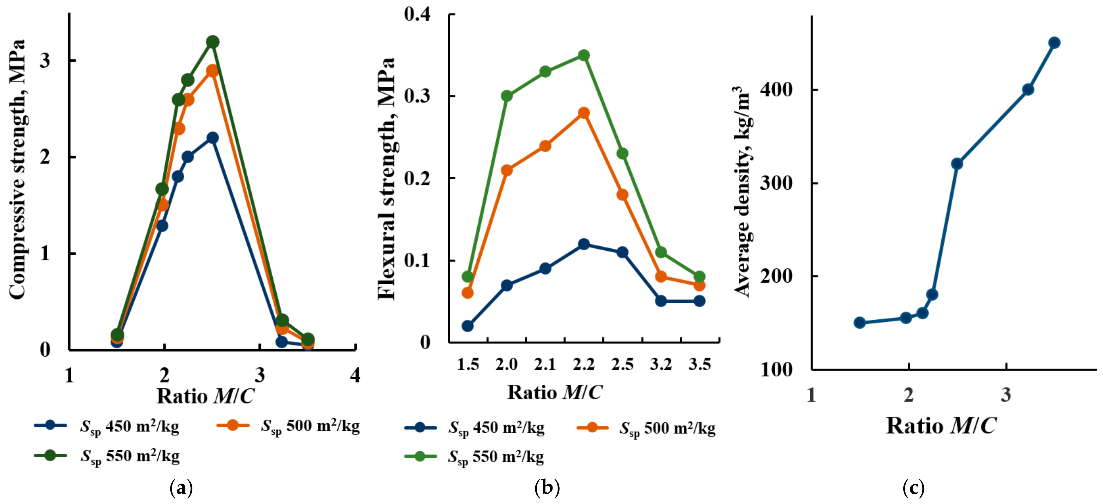
To determine the effect of the ratio of cullet fractions on the strength of glass-filled porous material, the mass ratio of finely milled glass to crushed glass (hereinafter M/C, milled over crushed glass) was varied. The results of the strength measurements of the samples are shown in Figure 6. The optimal ratio between finely milled and crushed cullet M/C is 1.97–2.24 to obtain maximum strength characteristics; with these ratios, the maximum strength of aerated concrete samples is achieved with an average density of samples in the dry state from 150 to 300 kg/m3 (Figure 6).
Both at high (M/C = 1.5) and at low contents of a large fraction of cullet, sufficient strength of the samples is not achieved (Figure 6). At low contents of crushed cullet, the density of the samples increases significantly, while they become brittle.
The ratio of glass fractions also affects the thermal conductivity of cellular concrete samples: when the M/C ratio increases from 1.5 to 3.5, the thermal conductivity passes through the maximum (Table 4).
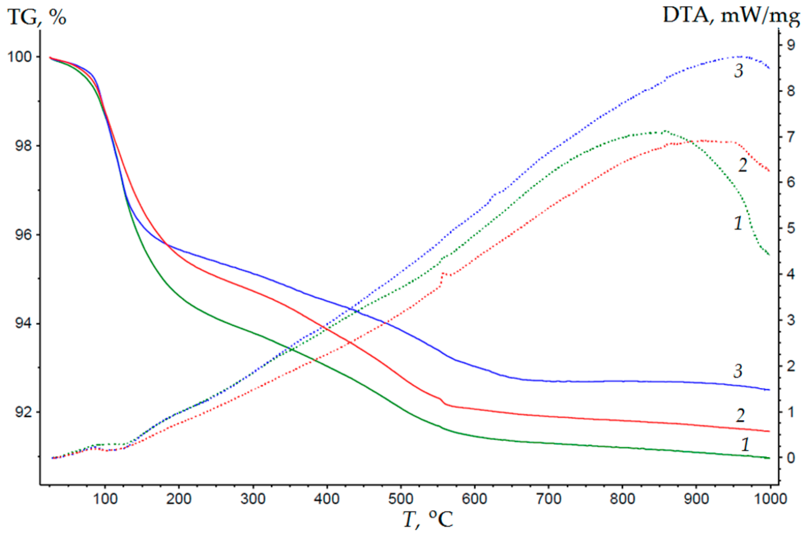
Phase transitions occurring during the heating of cellular concrete samples were evaluated using differential thermal analysis (Figure 7). As follows from the results of the DTA, the hydrate structures containing crystallization water remain at a small amount in the composition of cellular concrete after drying, and the loss of water occurs at a temperature range of 100–150 °C (4–6% in the TG curve, Figure 7).
With a temperature increase in the range from 150 to 550 °C, polycondensation processes occur in the structure of the cell walls, accompanied by a loss of water in amount of 3–5%. At this temperature range, dehydration of hydrosilicates occurs. When the temperature rises from 550 to 850–950 °C (the upward part of the exothermic peak), both liquid glass and finely milled cullet crystallize, accompanied by an exothermic peak of 7–9 mW/mg without mass loss (Figure 7). In addition, polymorphic transformations of calcium silicates occur in this temperature range, accompanied by a change in the volume of minerals. At higher temperatures, melting of samples is observed (descending part at more than 900 °C temperature region). An increase in the proportion of finely milled cullet in the composition leads to a decrease in the upper limit of the temperature range from 800 to 400 °C. This is due to the fact that phase transformations of samples with finely milled cullet, accompanied by the destruction, occur at lower temperatures.
Thus, the dispersion of glass has a significant effect on the strength of the cell walls of porous concrete. The greatest strength of the samples is achieved with a ratio of milled to crushed glass M/C = 1.97–2.24. In this case, small glass particles participate in the formation of a polymer silicate bond, and coarse particles play the role of a reinforcing component.

3.2.2. Influence of Liquid Glass Density on the Density and Strength of Cellular Concrete

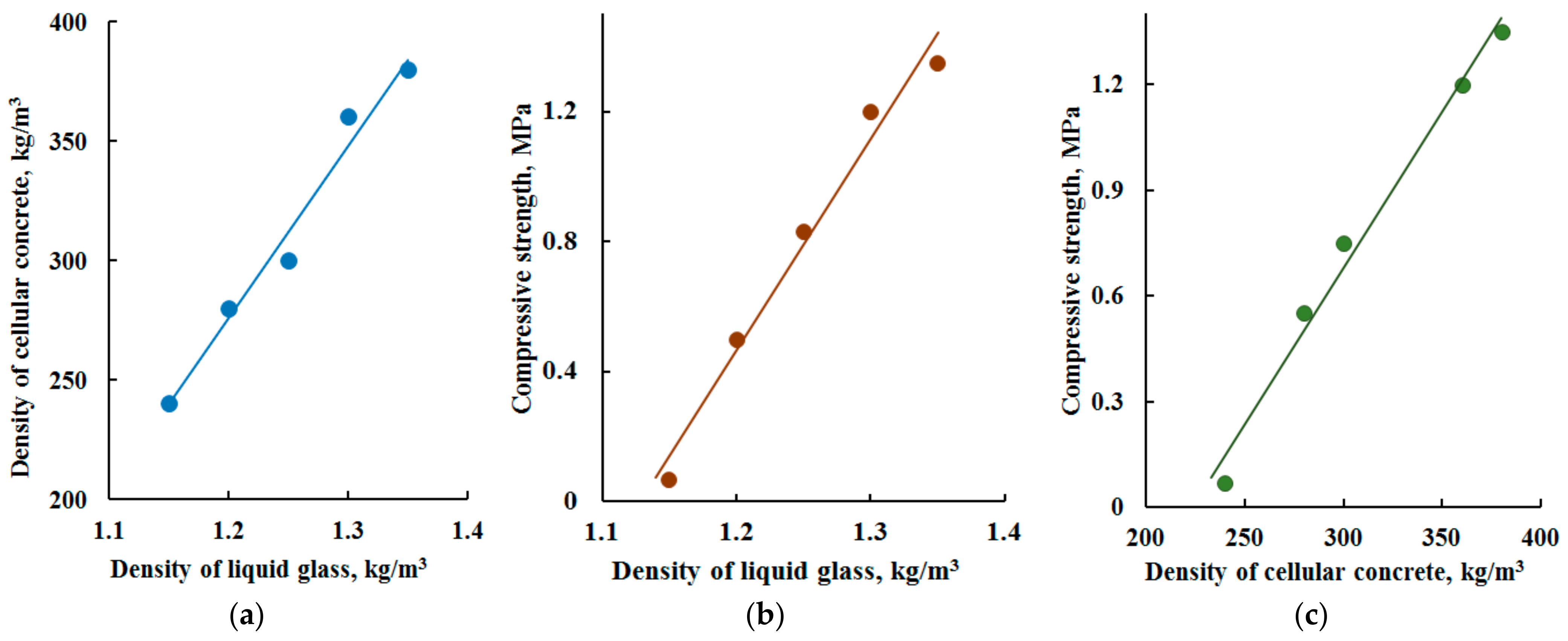
The density of liquid glass affects the intensity of hydration processes, the setting time, and as a consequence, the strength of the resulting porous material. The density of the liquid glass used in the production of glass-filled porous concrete varied in the range of 1130–1350 kg/m3. The composition of the mixtures and the conditions for obtaining samples are described in Section 3.2.1, the ratio between finely milled and crushed cullet was 2.24. It follows from the analysis of the obtained porous concrete that an increase in the density of liquid glass promotes both an increase in the density and the strength of cellular concrete (Figure 8). The dependence of the strength of aerated concrete on the density of liquid glass is close to linear in the range of 1200–1350 kg/m3, with a higher density of liquid glass the growth of the strength of porous concrete slows down. At the same time, there is not enough gas formation due to the high viscosity of the mixture. With a lower density of liquid glass (ρ = 1130–1200 kg/m3), it becomes impossible to obtain a strong porous structure of concrete, the cell walls quickly collapse under minor mechanical influence. An increase in the quantity of water in liquid glass of low density contributes to a decrease in the pH of the medium, resulting in the decrease in the intensity of amorphous silica dissolution, which leads to a decrease in the strength of the material. Thus, the optimal values of liquid glass density range from 1230 to 1350 kg/m3, at which it is possible to obtain final products of low density and sufficiently high strength.

3.2.3. Formation of a Porous Structure

The porosity of cellular concrete is characterized by the content of pores, their diameter and uniformity of distribution. Macropores of 1 mm or more in diameter are created in the concrete due to gas formation. In highly porous systems, which include cellular concrete with a macropore volume of more than 50%, the porosity value can be more than 90%. The material of the cell walls occupies relatively small area in such systems. To obtain the samples of glass-filled porous concrete, the compositions were selected in accordance with Section 3.2.1 of this study; the ratio between finely milled and crushed cullet was 2.24, the density of liquid glass varied in the range of 1130–1350 kg/m3. The macro- and microstructure of the obtained cellular concrete samples were evaluated according to electron microscopy data, the macroporosity of the samples was determined by measurements using microscopic data (Figure 9). The results of macroporosity determination depending on the density of the liquid glass is shown in Table 5.
Cellular concrete samples are characterized by high total porosity, while most of the pores are closed, which contributes to reduced thermal conductivity of the material (Table 4). The shape of the pores is close to spherical, and their diameter varies quite widely depending on the density of the material: with a sample density of 280–300 kg/m3, the pore sizes are 650–850 μm; with a higher density of the samples, the pore sizes are reduced to 350–600 μm (Figure 9).
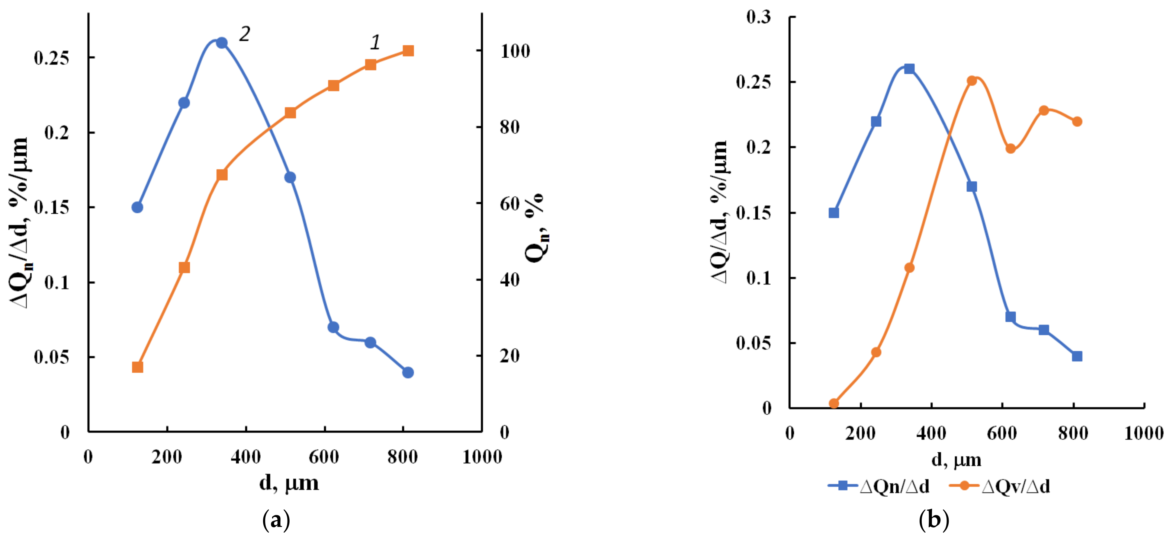
Based on the calculations of the size and number of pores, integral and differential pore size distribution curves were plotted (Figure 10). Calculations of the arithmetic mean (dN) and volume mean (dV) pore diameters were performed, and sample polydispersity (P = dN/dV) was estimated.
In accordance with the results of the calculations of porosity parameters, cellular concrete samples with low density are characterized by a less homogeneous porous structure (p = 0.52) due to a larger pore size distribution than samples with high density (p = 0.68).
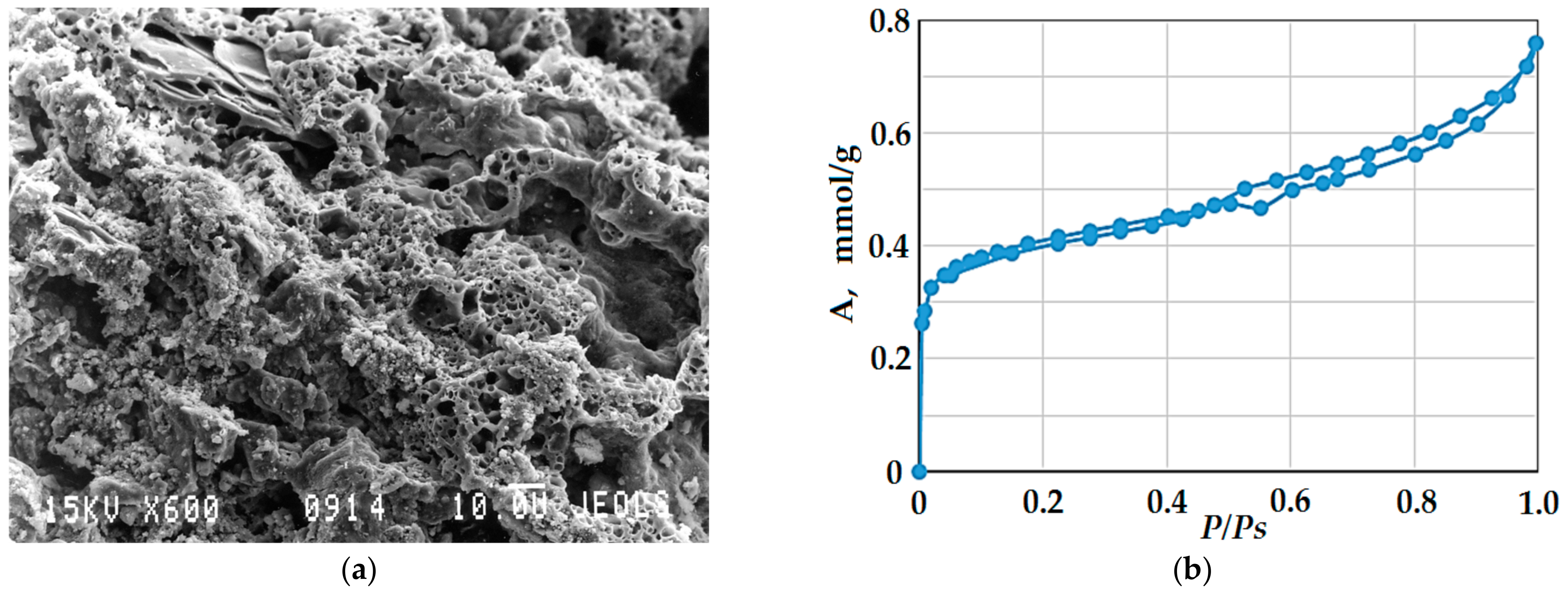
The structural characteristics of cell walls in porous concrete were studied using the low-temperature adsorption–desorption of nitrogen. The cell walls have a spongy structure typical for hardened gels (Figure 11a).
Adsorption measurements showed (Figure 11b) that at the initial region of the adsorption isotherm, there is an increase in the region of small relative pressure values due to polymolecular adsorption. In the region of 0.5–0.95 pressures hysteresis is observed on the isotherm, which indicates the occurrence of capillary condensation process in mesopores. This indicates that mesopores are of open cylindrical shape, their size according to the Pierce method is 1.5–2 nm, the specific volume of mesopores is approximatey 56.92 cm3/g.

3.2.4. Water Absorption and Water Resistance

Due to the high porosity of the obtained cellular concrete samples (Table 5) their water absorption was investigated. For this purpose, cubic samples of 10 × 10 × 10 cm3 were prepared, which were placed in containers with water. The results of water absorption determination by weight measurement of dry and water-saturated samples are shown in Figure 12. Water absorption by weight (WM) of aerated concrete samples varies from 36 to 38.5%, the difference between the samples does not exceed 0.5–2.6% (Figure 12). The water absorption of aerated concrete samples by volume (WV) at different densities of liquid glass in the range of 1200–1310 kg/m3 have almost the same values. Outside the limits of the liquid glass density the water absorption of cellular concrete changes significantly, which is explained by the formation of an extremely heterogeneous porous structure of the material. Samples based on liquid glass with ρ = 1130 kg/m3, in addition to open pores of different sizes, are characterized by the presence of a large quantity of closed pores and thin pore walls, which generally leads to a decrease in water absorption. When high density liquid glass with ρ = 1350 kg/m3 is used, the porous structure of the material is characterized by the presence of macro- and mesopores, as well as microcapillaries, which causes increased volumetric water absorption of the concrete samples.
Due to the sufficiently high water absorption of the studied concrete samples, which is 35–38.5 wt.%, it is practically significant to determine their water resistance (strength in a water-saturated state). The ability of cellular concrete samples to retain strength in a water-saturated state was evaluated using a softening coefficient (Cr), which is equal to the ratio of the strength of the water-saturated sample to the strength of the dry sample. The measurement results are presented in Table 6.
From the comparison of compressive strength of dry and water-saturated samples, it follows that the obtained porous materials retain strength with high water absorption (Table 6). This effect is due to the hydrophobic nature of the glass-filled material, which helps to reduce water adsorption on the cell walls and to remove water through open porosity during drying. In general, the water absorption and water resistance of the obtained porous materials does not show a significant dependence on the density of liquid glass, but depends greatly on the formed porous structure of cellular concrete and on the ratio of the initial raw components.

3.3. Application of Non-Autoclaved Ultra-Lightweight Cellular Concrete as a Building Material

To determine the application area of ultralight glass-filled cellular concrete, its basic properties were compared with the properties of similar materials described in the literature [44,45] and available at the construction materials market. Table 7 shows the characteristics of autoclaved and non-autoclaved light cellular concretes, including the properties of the material obtained in this work.
From the analysis of the data obtained, it follows that the density of the glass-filled cellular concrete belongs to the group of the lightest cement-containing materials (Table 7). To determine the possibility of using the obtained material in the production of building products and structures [46], it is necessary to correlate its strength characteristics with the regulatory requirements for cellular concretes. In accordance with the specifications for precast autoclaved aerated concrete masonry units, the compressive strength of the cellular material must be at least 1.5 N/mm2 (or ≥1.5 MPa) [47] or 2 MPa [48] with a dry density less than 1000 kg/m3 [47] or equal to 350–450 kg/m3 [48], respectively. The maximum strength of the material obtained in the work (up to 2 MPa) is achieved at the highest dry density of 320 kg/m3, therefore, taking into account the requirements of the above standards, glass-filled ultra-lightweight cellular concrete cannot be used for structural purposes (for example, for the construction of bearing walls). Also, the resulting porous material, given its high water absorption (up to 38.5%, Figure 12), it is impractical to use in conditions of high humidity, in particular for external structures, due to its low strength. The thermal conductivity of the material takes low values of 0.05–0.09 W/(K·m) which is at the level of traditional thermal insulation materials (mineral wool, foamed glass, perlite, etc. [29]).
Thus, the low thermal conductivity of such a material in combination with low density and acceptable strength (Table 7) allows us to consider it as an effective non-combustible insulating material. Also, the cellular blocks can be used to build non-bearing internal walls, as well as infill masonry. The features of the process of forming the structure of non-autoclaved glass-filled cellular concrete make it possible to obtain products of any shape and size, as well as to fill the space without the use of formwork.

4. Conclusions

  • An ultra-lightweight glass-filled cellular concrete based on Portland cement, glass waste and liquid glass is proposed. A mixture of sodium hexafluorosilicate and hydroxide is used as a hardening activator, and aluminum powder serves as a gas-forming agent. Mixing of the initial components initiates a complex of hydrolytic and gas-forming exothermic reactions leading to heating (80–100 °C), foaming and subsequent solidification of the system to form a porous silicate stone for 20–40 min. The obtained material does not require additional heat treatment. By varying the ratio and dispersion of the components, a cellular material with the following characteristics can be obtained: an average density in the dry state of 150–320 kg/m3; a compressive strength and bending strength of 2.0 MPa and 0.38 MPa, respectively; a thermal conductivity coefficient of 0.05–0.09 W/(K·m); a maximum operating temperature of 800 °C. Optimal porosity and strength of the material are achieved by using a mixture of crushed cullet (modulus of fineness Fm = 0.945) with ground glass (Ssp = 450–550 m2/kg) with a mass ratio of ground/coarse equal to 1.97–2.24.
  • The mechanism of formation of a durable porous structure of glass-filled cellular concrete consists of partial dissolution and subsequent joint solidification of the reaction layer at the ‘solution/glass particle’ interface due to the formation of a three-dimensional structural framework. The stabilization of the structure is provided by the reinforcing action of coarse glass particles and by the formation of insoluble compounds (silicates and aluminosilicates). The total porosity of the samples, depending on the density, reaches 68–85%, and the closed porosity is 54–76%, which causes low thermal conductivity of the samples, thereby determining high performance characteristics. The interpore walls have the structure of a solidified gel and are characterized by the presence of micropores, the size of which is 1.5–2 nm, and the specific volume of mesopores reaches 57 cm3/g. Despite the high water absorption (36–38 wt.%), the resulting porous material is characterized by high water resistance.
  • Based on a comparison of the characteristics of the obtained material with known data for autoclaved and non-autoclaved lightweight cellular concretes, a conclusion was made about the possibility of using the ultra-lightweight glass-filled cellular concrete as a heat and sound insulation material, as well as a repairing composition. The cellular concrete blocks can be used for the infill masonry and for the construction of non-bearing internal walls. The proposed material has the following advantages: the energy efficiency of the production technology compared to autoclaved aerated concrete; the resource efficiency of the technology due to the use of a small proportion of cement (9–12%) and a large proportion of glass waste (38–47%); incombustibility of the material; environmental expediency due to the use of non-degradable glass waste.

Author Contributions

Conceptualization, S.V.S. and A.V.K.; methodology, S.V.S.; software A.V.K.; validation, S.V.S. and A.V.K.; formal analysis, S.V.S. and A.V.K.; investigation, S.V.S. and A.V.K.; resources, S.V.S.; data curation A.V.K.; writing—original draft preparation, S.V.S.; writing—review and editing, A.V.K.; visualization, S.V.S. and A.V.K.; supervision, S.V.S.; project administration, S.V.S.; funding acquisition, S.V.S. and A.V.K. All authors have read and agreed to the published version of the manuscript.

Funding

The research was carried out with the financial support of the Moscow State University of Civil Engineering.

Data Availability Statement

The data presented in this study are available on request from the corresponding author.

Conflicts of Interest

The authors declare no conflict of interest.

References

  1. Czarnecki, S.; Rudner, M. Recycling of materials from renovation and demolition of building structures in the spirit of sustainable material engineering. Buildings 2023, 13, 1842. [Google Scholar] [CrossRef]
  2. Roland, C.; Martin, G.; Mair, S. Sustainability and the circular economy. In Assessing Progress towards Sustainability: Frameworks, Tools and Case Studies; Elsevier: Oxford, UK, 2022; pp. 35–56. [Google Scholar]
  3. Adekomaya, O.; Majozi, T. Mitigating environmental impact of waste glass materials: Review of the existing reclamation options and future outlook. Environ. Sci. Pollut. Res. 2021, 28, 10488. [Google Scholar] [CrossRef] [PubMed]
  4. Bento, A.C.; Kubaski, E.T.; Sequinel, T.; Pianaro, S.A.; Varela, J.A.; Tebcherani, S.M. Glass foam of macroporosity using glass waste and sodium hydroxide as the foaming agent. Ceram. Int. 2013, 39, 2423. [Google Scholar] [CrossRef]
  5. Chong, F.; Jianwei, L.; Gao, Y.; Dagestani, A.A.; Liu, W.; Luo, X.; Baobao, Z.; Wu, H.; Huang, M.; Lifu, L.; et al. Recycling of waste glass as raw materials for the preparation of self-cleaning, light-weight and high-strength porous ceramics. J. Clean. Prod. 2021, 317, 128395. [Google Scholar]
  6. Andreola, F.; Lancellotti, I.; Taurino, R.; Leonelli, C.; Barbieri, L. Production of cement blocks and new ceramic materials with high content of glass waste. Key Eng. Mater. 2016, 663, 34. [Google Scholar] [CrossRef]
  7. Heriyanto; Pahlevani, F.; Sahajwalla, V. From waste glass to building materials—An innovative sustainable solution for waste glass. J. Clean. Prod. 2018, 191, 192. [Google Scholar] [CrossRef]
  8. Polley, C.; Cramer, S.M.; de la Cruz, R.V. Potential for using waste glass in Portland cement concrete. J. Mater. Civ. Eng. 1998, 10, 210. [Google Scholar] [CrossRef]
  9. Shao, Y.; Lefort, T.; Moras, S.; Rodriguez, D. Studies on concrete containing ground waste glass. Cem. Concr. Res. 2000, 30, 91. [Google Scholar] [CrossRef]
  10. Dyer, T.D.; Dhir, R.K. Chemical reactions of glass cullet used as cement component. J. Mater. Civ. Eng. 2001, 13, 412. [Google Scholar] [CrossRef]
  11. Topcu, I.B.; Canbaz, M. Properties of concrete containing waste glass. Cem. Concr. Res. 2004, 34, 267. [Google Scholar] [CrossRef]
  12. Corinaldesi, V.; Gnappi, G.; Moriconi, G.; Montenero, A. Reuse of ground waste glass as aggregate for mortars. Waste Manag. 2005, 25, 197. [Google Scholar] [CrossRef] [PubMed]
  13. Taha, B.; Nounu, G. Properties of concrete contains mixed colour waste recycled glass as sand and cement replacement. Constr. Build. Mater. 2008, 22, 713. [Google Scholar] [CrossRef]
  14. Patel, D.; Tiwari, R.P.; Shrivastava, R.; Yadav, R.K. Effective utilization of waste glass powder as the substitution of cement in making paste and mortar. Constr. Build. Mater. 2019, 199, 406. [Google Scholar] [CrossRef]
  15. Ahmad, J.; Zhou, Z.; Usanova, K.I.; Vatin, N.I.; El-Shorbagy, M.A. A Step towards concrete with partial substitution of waste glass (WG) in concrete: A review. Materials 2022, 15, 2525. [Google Scholar] [CrossRef] [PubMed]
  16. Younsi, A.; Mahi, M.A.; Hamami, A.E.A.; Belarbi, R.; Bastidas-Arteaga, E. High-volume recycled waste glass powder cement-based materials: Role of glass powder granularity. Buildings 2023, 13, 1783. [Google Scholar] [CrossRef]
  17. Rivera, J.F.; Cuarán-Cuarán, Z.I.; Vanegas-Bonilla, N.; Mejía de Gutiérrez, R. Novel use of waste glass powder: Production of geopolymeric tiles. Adv. Powder Technol. 2018, 29, 3448. [Google Scholar] [CrossRef]
  18. Henao Rios, L.M.; Hoyos Triviño, A.F.; Villaquirán-Caicedo, M.A.; Mejía de Gutiérrez, R. Effect of the use of waste glass (as precursor, and alkali activator) in the manufacture of geopolymer rendering mortars and architectural tiles. Constr. Build. Mater. 2023, 363, 129760. [Google Scholar] [CrossRef]
  19. Adesina, A. Durability and microstructural characteristics of alkali activated materials made with waste glass as precursor: A review. Clean. Mater. 2022, 6, 100134. [Google Scholar] [CrossRef]
  20. Tushar, Q.; Salehi, S.; Santos, J.; Zhang, G.; Bhuiyan, M.A.; Arashpour, M.; Giustozzi, F. Application of recycled crushed glass in road pavements and pipeline bedding: An integrated environmental evaluation using LCA. Sci. Total Environ. 2023, 881, 163488. [Google Scholar] [CrossRef]
  21. Abu Salem, Z.T.; Khedawi, T.S.; Baker, M.B.; Abendeh, R. Effect of waste glass on properties of asphalt concrete mixtures. Jordan J. Civ. Eng. 2017, 11, 117. [Google Scholar]
  22. Kalampokis, S.; Kalama, D.; Kesikidou, F.; Stefanidou, M.; Manthos, E. Assessment of waste glass incorporation in asphalt concrete for surface layer construction. Materials 2023, 16, 4938. [Google Scholar] [CrossRef] [PubMed]
  23. Burghardt, T.E.; Ettinger, K.; Köck, B.; Hauzenberger, C. Glass beads for road markings and other industrial usage: Crystallinity and hazardous elements. Case Stud. Constr. Mater. 2022, 17, e01213. [Google Scholar] [CrossRef]
  24. Cozzarini, L.; Marsich, L.; Ferluga, A.; Schmid, C. Life cycle analysis of a novel thermal insulator obtained from recycled glass waste. Dev. Built Environ. 2020, 3, 100014. [Google Scholar] [CrossRef]
  25. Cozzarini, L.; De Lorenzi, L.; Barago, N.; Sbaizero, O.; Bevilacqua, P. Expanded Glass for Thermal and Acoustic Insulation from Recycled Post-Consumer Glass and Textile Industry Process Waste. Materials 2023, 16, 1721. [Google Scholar] [CrossRef] [PubMed]
  26. König, J.; Petersen, R.R.; Yue, Y. Fabrication of highly insulating foam glass made from CRT panel glass. Ceram. Int. 2015, 41, 9793. [Google Scholar] [CrossRef]
  27. Hamada, H.M.; Shi, J.; Abed, F.; Humada, A.M.; Majdi, A. Recycling solid waste to produce eco-friendly foamed concrete: A comprehensive review of approaches. J. Environ. Chem. Eng. 2023, 11, 111353. [Google Scholar] [CrossRef]
  28. Das, A.; Mahanwar, P. A brief discussion on advances in polyurethane applications. Adv. Ind. Eng. Polym. Res. 2020, 3, 93. [Google Scholar] [CrossRef]
  29. Kumar, D.; Alam, M.; Zou, P.X.W.; Sanjayan, J.G.; Memon, R.A. Comparative analysis of building insulation material properties and performance. Renew. Sustain. Energy Rev. 2020, 131, 110038. [Google Scholar] [CrossRef]
  30. Schiavoni, S.; D’Alessandro, F.; Bianchi, F.; Asdrubali, F. Insulation materials for the building sector: A review and comparative analysis. Renew. Sustain. Energy Rev. 2016, 62, 988. [Google Scholar] [CrossRef]
  31. Yang, S.; Zhang, L. Research on Properties of Rock-mineral Wool as Thermal Insulation Material for Construction. Adv. Mater. Res. 2012, 450-451, 618. [Google Scholar] [CrossRef]
  32. Wongkeo, W.; Chaipanich, A. Compressive strength, microstructure and thermal analysis of autoclaved and air cured structural lightweight concrete made with coal bottom ash and silica fume. Mater. Sci. Eng. A 2010, 527, 3676. [Google Scholar] [CrossRef]
  33. Qu, X.; Zhao, X. Previous and present investigations on the components, microstructure and main properties of autoclaved aerated concrete—A review. Constr. Build. Mater. 2017, 135, 505. [Google Scholar] [CrossRef]
  34. Sulhadi; Susanto; Priyanto, A.; Fuadah, A.; Aji, M.P. Performance of Porous Composite from Waste Glass on Salt Purification Process. Procedia Eng. 2017, 170, 41. [Google Scholar] [CrossRef]
  35. Takei, T.; Ota, H.; Dong, Q.; Miura, A.; Yonesaki, Y.; Kumada, N.; Takahashi, H. Preparation of porous material from waste bottle glass by hydrothermal treatment. Ceram. Int. 2012, 38, 2153. [Google Scholar] [CrossRef]
  36. Esmaily, H.; Nuranian, H. Non-autoclaved high strength cellular concrete from alkali activated slag. Constr. Build. Mater. 2012, 26, 200. [Google Scholar] [CrossRef]
  37. Miryuk, O.A. Porous materials based on liquid glass. MOJ App. Bio. Biomech. 2018, 2, 170. [Google Scholar]
  38. Liu, Y.-L.; Liu, C.; Qian, L.-P.; Wang, A.-G.; Sun, D.-S.; Guo, D. Foaming processes and properties of geopolymer foam concrete: Effect of the activator. Constr. Build. Mater. 2023, 391, 131830. [Google Scholar] [CrossRef]
  39. Hribar, U.; Spreitzer, M.; König, J. Applicability of water glass for the transfer of the glass-foaming process from controlled to air atmosphere. J. Clean. Prod. 2021, 282, 125428. [Google Scholar] [CrossRef]
  40. EN 12390-3:2019; Testing Hardened Concrete—Part 3: Compressive Strength of Test Specimens. European Committee for Standardization: Brussels, Belgium, 2019.
  41. EN 12390-5:2019; Testing Hardened Concrete—Part 5: Flexural Strength of Test Specimens. European Committee for Standardization: Brussels, Belgium, 2019.
  42. Samchenko, S.V.; Aleksandrova, O.V.; Zaitseva, A.A. Aerated concrete based on cullet and liquid glass. Mater. Sci. Forum 2019, 974, 362. [Google Scholar] [CrossRef]
  43. Samchenko, S.V.; Zaitseva, A.A. Possibility of the use of ground glass break in the production of aerated concrete. Solid State Phenom. 2022, 334, 233. [Google Scholar] [CrossRef]
  44. Huang, Z.; Zhang, T.; Wen, Z. Proportioning and characterization of Portland cement-based ultra-lightweight foam concretes. Constr. Build. Mater. 2015, 79, 390. [Google Scholar] [CrossRef]
  45. Michelini, E.; Ferretti, D.; Miccoli, L.; Parisi, F. Autoclaved aerated concrete masonry for energy efficient buildings: State of the art and future developments. Constr. Build. Mater. 2023, 402, 132996. [Google Scholar] [CrossRef]
  46. Chaipanich, A.; Chindaprasirt, P. The properties and durability of autoclaved aerated concrete masonry blocks. In Eco-Efficient Masonry Bricks and Blocks: Design, Properties and Durability; Woodhead Publishing: Cambridge, UK, 2015; pp. 215–230. [Google Scholar]
  47. EN 771-4:2011+A1:2015; Specification for Masonry Units—Part 4: Autoclaved Aerated Concrete Masonry Units. European Committee for Standardization: Brussels, Belgium, 2015.
  48. ASTM C1691-21; Standard Specification for Unreinforced Autoclaved Aerated Concrete (AAC) Masonry Units. Annual Book of ASTM Standards, Volume 04.05. ASTM International: West Conshohocken, PA, USA, 2021.
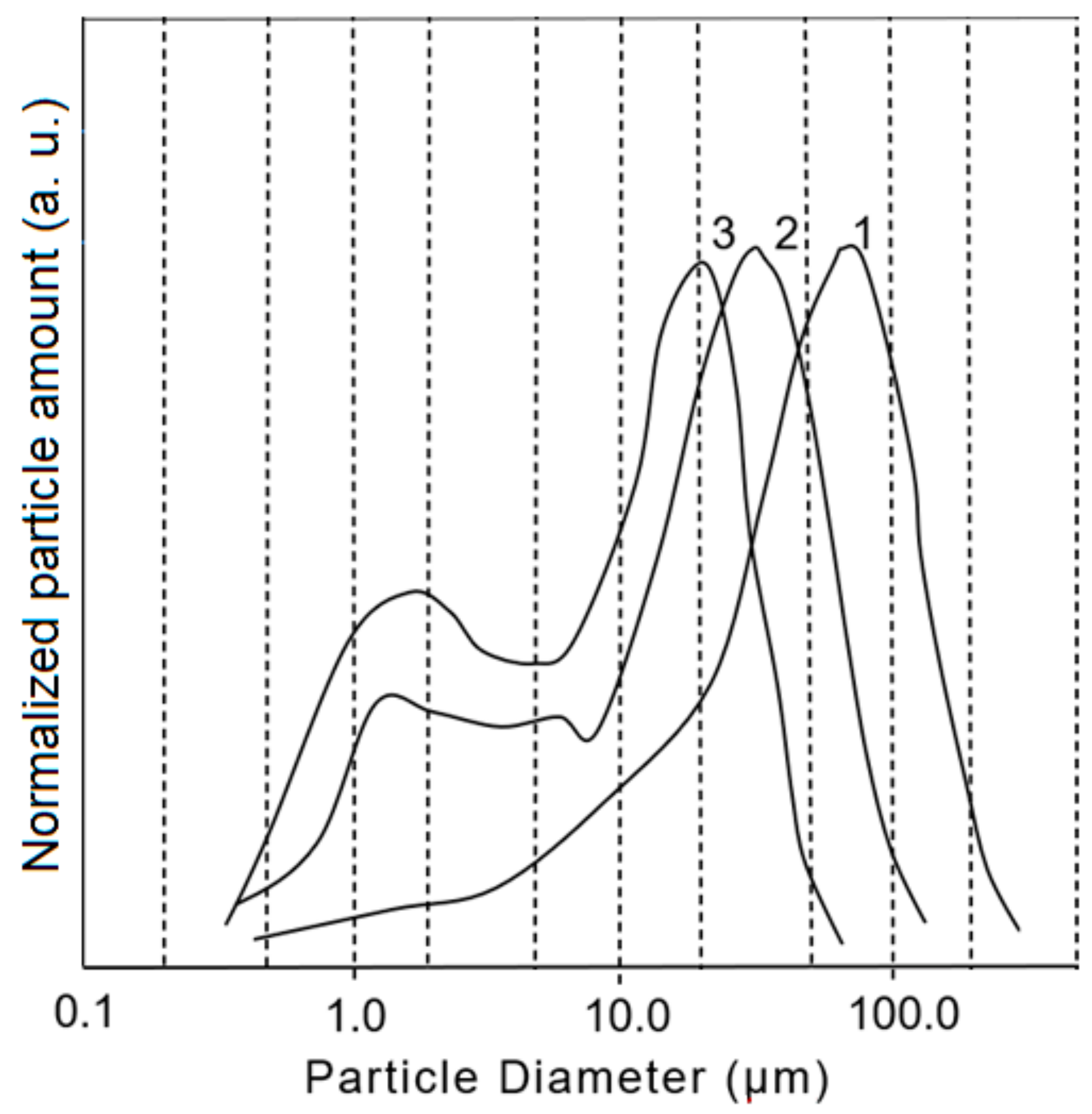
Figure 1. Size distribution of glass particles with different specific surface area: (1) Ssp = 450 m2/kg; (2) Ssp = 500 m2/kg; (3) Ssp = 550 m2/kg.
Buildings 14 00017 g001
Figure 2. Microphotographs of particles of various size fractions of waste glass: (a) large-fraction cullet; (b) ground cullet with Ssp = 450 m2/kg; (c) ground cullet with Ssp = 500 m2/kg; (d) ground cullet with Ssp = 550 m2/kg.
Buildings 14 00017 g002
Figure 3. Dependence of the strength of cellular concrete samples based on waste glass and liquid glass on the specific surface area of milled glass (see Table 4).
Buildings 14 00017 g003
Figure 4. Infrared spectrum of the material of cell walls in glass-filled cellular concrete with a density of 360 kg/m3.
Buildings 14 00017 g004
Figure 5. XRD pattern of the material of cell walls in glass-filled cellular concrete with a density of 360 kg/m3.
Buildings 14 00017 g005
Figure 6. Dependence of compressive strength (a), flexural strength (b) and density (c) of glass-filled cellular concrete samples in the dry state with a density of 360 kg/m3 on the mass ratio of finely milled and crushed glass M/C.
Buildings 14 00017 g006
Figure 7. TG (solid) and DTA (dot) linear heating curves (heating rate 10 K/min) of glass-filled cellular concrete samples with different dispersion of glass filler: (1) Ssp = 550 m2/kg, (2) Ssp = 500 m2/kg, and (3) Ssp = 450 m2/kg.
Buildings 14 00017 g007
Figure 8. Dependences of the cellular concrete density (a) on the density of liquid glass, (b) the strength of concrete on the density of liquid glass, and (c) the strength of cellular concrete on its density.
Buildings 14 00017 g008
Figure 9. Micrographs of the porous structure of glass-filled cellular concrete samples with different densities: (a) 280 kg/m3; (b) 300 kg/m3; (c) 360 kg/m3; (d) 380 kg/m3. The grid lines, cell numbers, and diameters represent a way to determine the size of pores in the material structure.
Buildings 14 00017 g009aBuildings 14 00017 g009b
Figure 10. Integral (1) and differential (2) curves of (a) arithmetic mean pore size distribution and (b) differential curves of arithmetic and volume mean pore size distribution for a sample with a density of 380 kg/m3.
Buildings 14 00017 g010
Figure 11. Microphotograph of (a) a fragment of the cell walls and (b) an isotherm of low-temperature adsorption–desorption of nitrogen for a sample of glass-filled porous concrete with a density of 360 kg/m3.
Buildings 14 00017 g011
Figure 12. Dependence of water absorption of glass-filled cellular concrete by weight (WM) and by volume (WV) on the density of the used liquid glass.
Buildings 14 00017 g012
Table 1. Chemical composition of cullet used in the work.
OxideSiO2Al2O3Fe2O3CaO + MgONa2O + K2OSO3
Content, wt.%71.5–72.62–2.60.1–0.2510–10.515.0–16.00.3–0.4
Table 2. Fractional composition of coarse crushed and highly dispersed milled cullet.
Particle Size Mass Fraction, wt.%
Coarse CulletMilled Cullet,
Ssp = 450 m2/kg
Milled Cullet,
Ssp = 500 m2/kg
Milled Cullet,
Ssp = 550 m2/kg
d > 1 mm10.5000
0.2 < d < 1.0 mm21.55.21.71.9
0.063 < d < 0.2 mm49.376.189.791.3
d < 0.063 mm13.218.78.66.8
Table 3. Average sizes of waste glass particles.
SampleGlass Particle Size, μm
Volume Mean D43Surface Mean D32Arithmetic Mean D10
μm3Ratio to the Reference Sampleμm2Ratio to the Reference SampleμmRatio to the Reference Sample
Milled cullet
Ssp = 450 m2/kg
46.68-19.21-15.45-
Milled cullet
Ssp = 500 m2/kg
22.772.0511.431.6812.161.27
Milled cullet
Ssp = 550 m2/kg
22.342.0911.081.7311.611.33
Table 4. Thermal conductivity of cellular concrete samples.
ParameterMilled Glass to Crushed Glass (M/C) Ratio
1.51.972.142.242.53.233.5
Thermal conductivity coefficient W/(m × K)0.050.060.060.090.0950.050.015
Table 5. Macroporosity of glass-filled aerated concrete samples at different densities of liquid glass.
NoLiquid Glass Density, kg/m3Total Porosity, %Open Porosity, %Closed Porosity, %
1135068.714.6354.07
2131073.510.0563.45
3123078.910.7768.13
4120082.410.7271.68
5113085.68.9076.7
Table 6. Effect of water saturation on the compressive strength of cellular concrete at different densities of liquid glass used.
Liquid Glass Density, kg/m3Compressive Strength of Dry Cellular Concrete Rdry, MPaCompressive Strength of Water-Saturated Cellular Concrete Rsat, MPaSoftening Coefficient, Cr
13501.351.320.98
13101.211.170.97
12300.830.800.96
12000.570.550.96
11300.070.060.95
Table 7. Characteristics of lightweight cellular concretes.
MaterialCharacteristics
Dry Density, kg/m3Compressive Strength, MPaThermal Conductivity, W/(K·m)Total Porosity, %Possible Applications
Non-autoclaved ultra-lightweight glass-filled cellular concrete (present work)150–3200.6–20.05–0.0968–85Thermal and acoustic insulation, repairing composition, infills, non-bearing internal walls
Non-autoclaved ultra-lightweight foam concrete [44]100–3000.1–10.043–0.07870–80Thermal and acoustic insulation
Commercial autoclaved aerated concrete masonry [45]250–3502–2.80.07–0.09≤85Infills and claddings
Commercial non-autoclaved foamed concrete (from open sources) *<5000.5–10.15-Roads and subbases, voids, mine shafts, basements and vaults, thermal insulators, complex formwork, tank filling
Note: * commercial name and manufacturer are not specified.
Disclaimer/Publisher’s Note: The statements, opinions and data contained in all publications are solely those of the individual author(s) and contributor(s) and not of MDPI and/or the editor(s). MDPI and/or the editor(s) disclaim responsibility for any injury to people or property resulting from any ideas, methods, instructions or products referred to in the content.