


Analytical Study of Structural Conformation and Prestressing State of Drum-Shaped Honeycomb Quad-Strut Cable Dome Structure with Different Calculation Methods


Abstract
1. Introduction

| Name | Year Built | Structural Form | Plane Size |
|---|---|---|---|
| Gymnastics Pavilion for the Asian Games in Seoul, Korea [3] | 1986 | ribbed ring | Diameter 119.8 m |
| Suncoast Dome, Florida, USA [23] | 1990 | ribbed ring | Diameter 210 m |
| Georgette Dome, Olympic Games, Atlanta, USA [24] | 1992 | sunflower-shaped | Oval 240 m × 192 m |
| La Plata Stadium, Argentina [25] | 2011 | sunflower-shaped | Intersection of two circles 219 m × 171 m |
| Tianjin Polytechnic University [26] | 2016 | Sunflower + Rib Ring Type | Oval 102 m × 83 m |
| Ya’an Tianquan County Gymnasium [4,27] | 2017 | Sunflower + Rib Ring Type | Diameter 77.3 m |
| Chengdu Fenghuangshan Sports Center | 2021 | Sunflower + inner ring truss type | 279 m × 234 m |
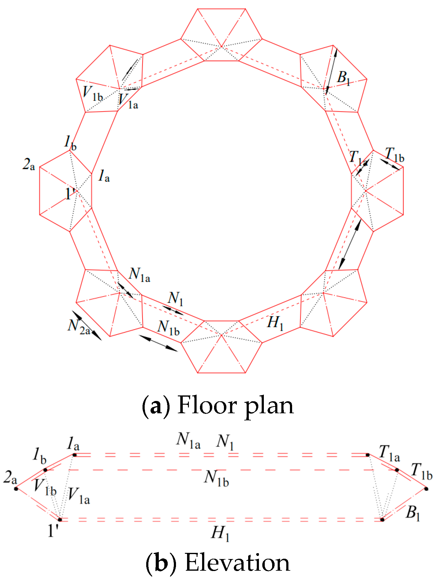
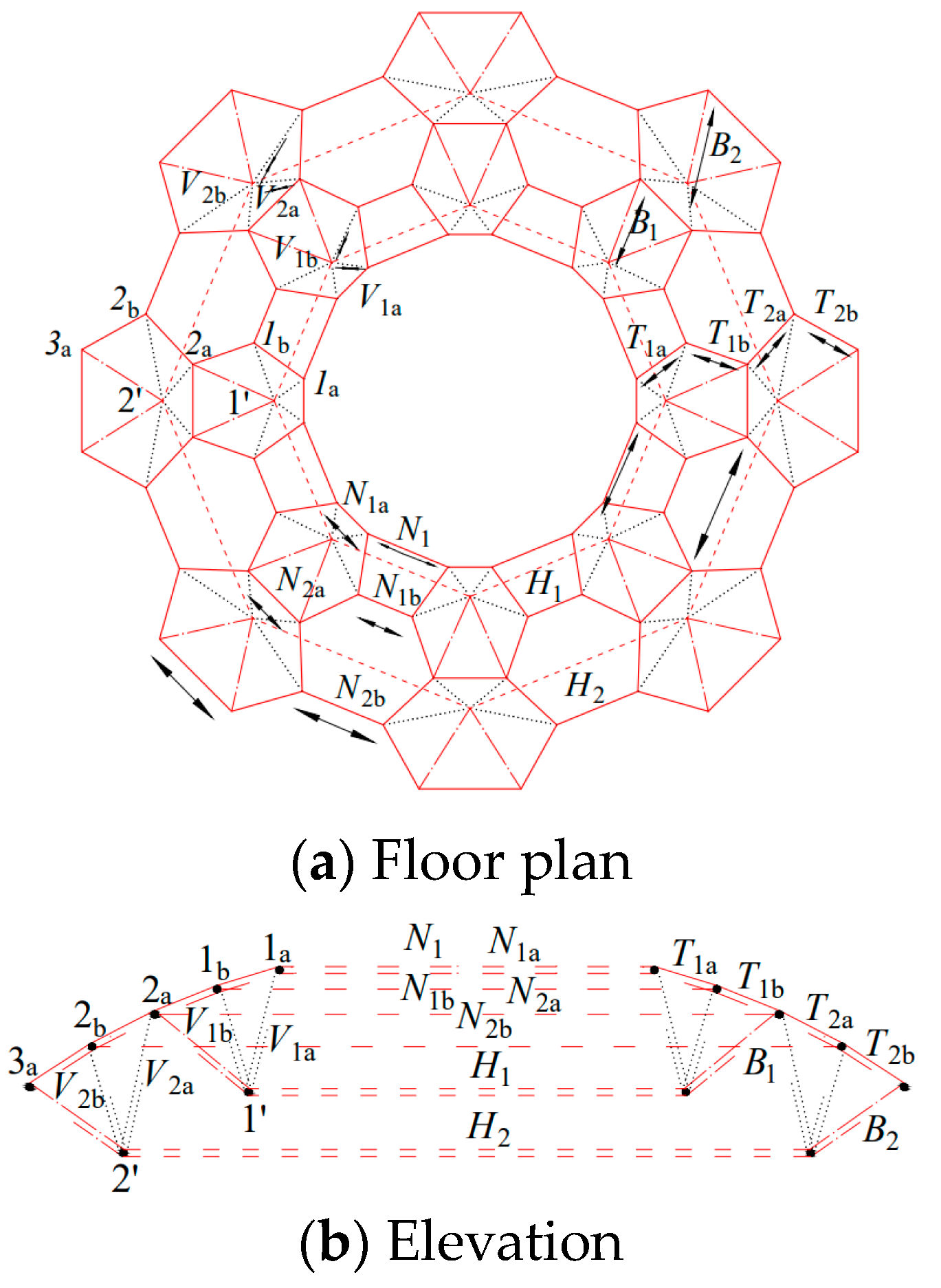
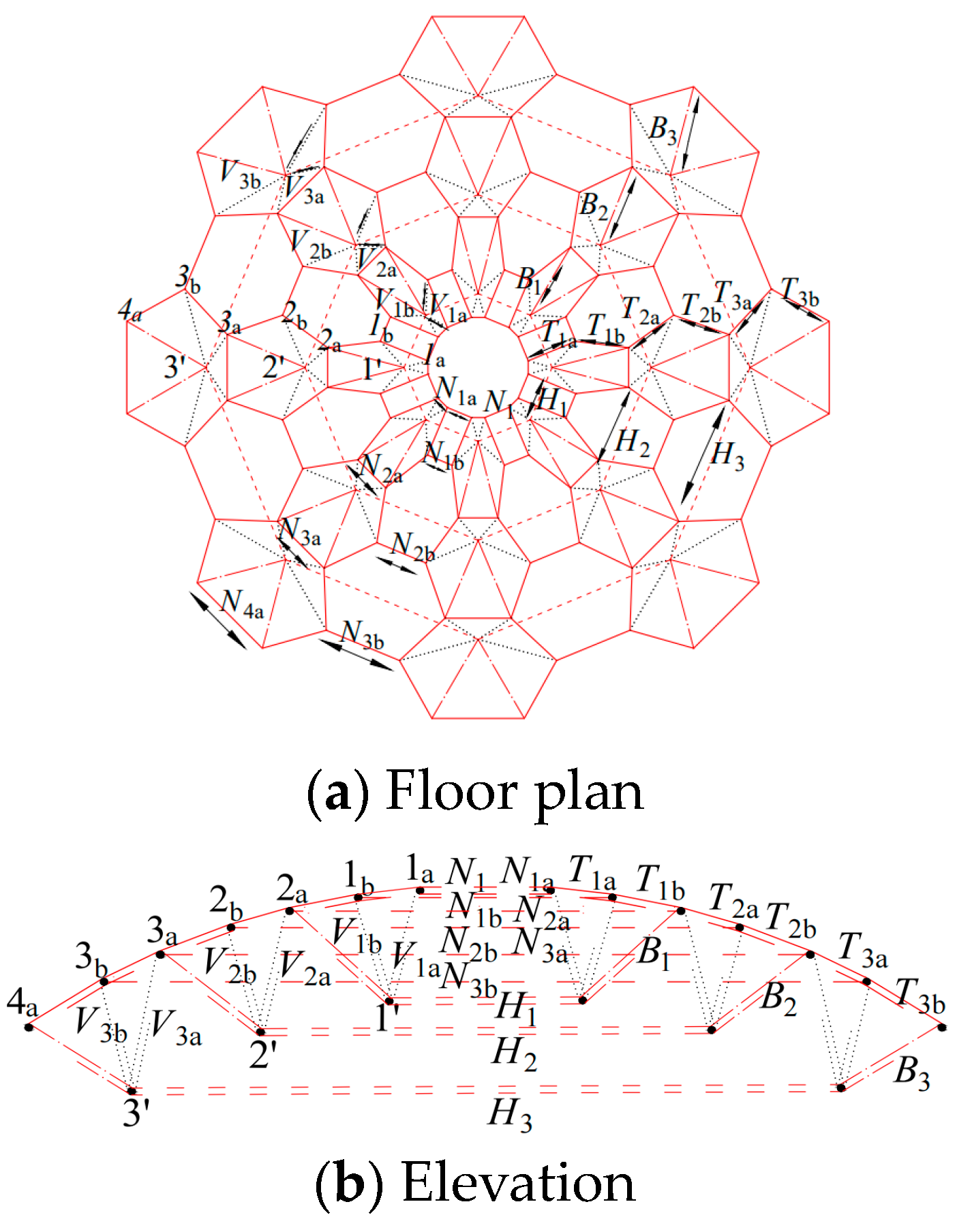
2. Structural Configuration and Characteristics
- (1)
- The drum-shaped honeycomb grid design of the cable dome includes only one ring cable and two diagonal cables connected to four struts. This design reduces the number of rings and diagonal cables compared to a Levy cable dome.
- (2)
- The drum-shaped honeycomb quad-strut type Ⅲ cable dome structure has a simple topology. For example, a small opening drum-shaped honeycomb quad-strut cable dome () consists of only 320 rod and cable units. The ratio of the total number of rods and cables in the structure is 3:7, which is higher compared to the commonly used Levy cable dome (1:5). Since the material cost of cables is often higher than that of the rods, the drum-shaped honeycomb quad-strut cable dome offers a cost advantage in terms of engineering and holds promising prospects for popularization and application.
3. Calculation of Internal Forces in Structural Prestressed State Rods
3.1. Succinct Analysis of Pre-Stressed States
3.2. Succinct Analysis of Pre-Stressed States
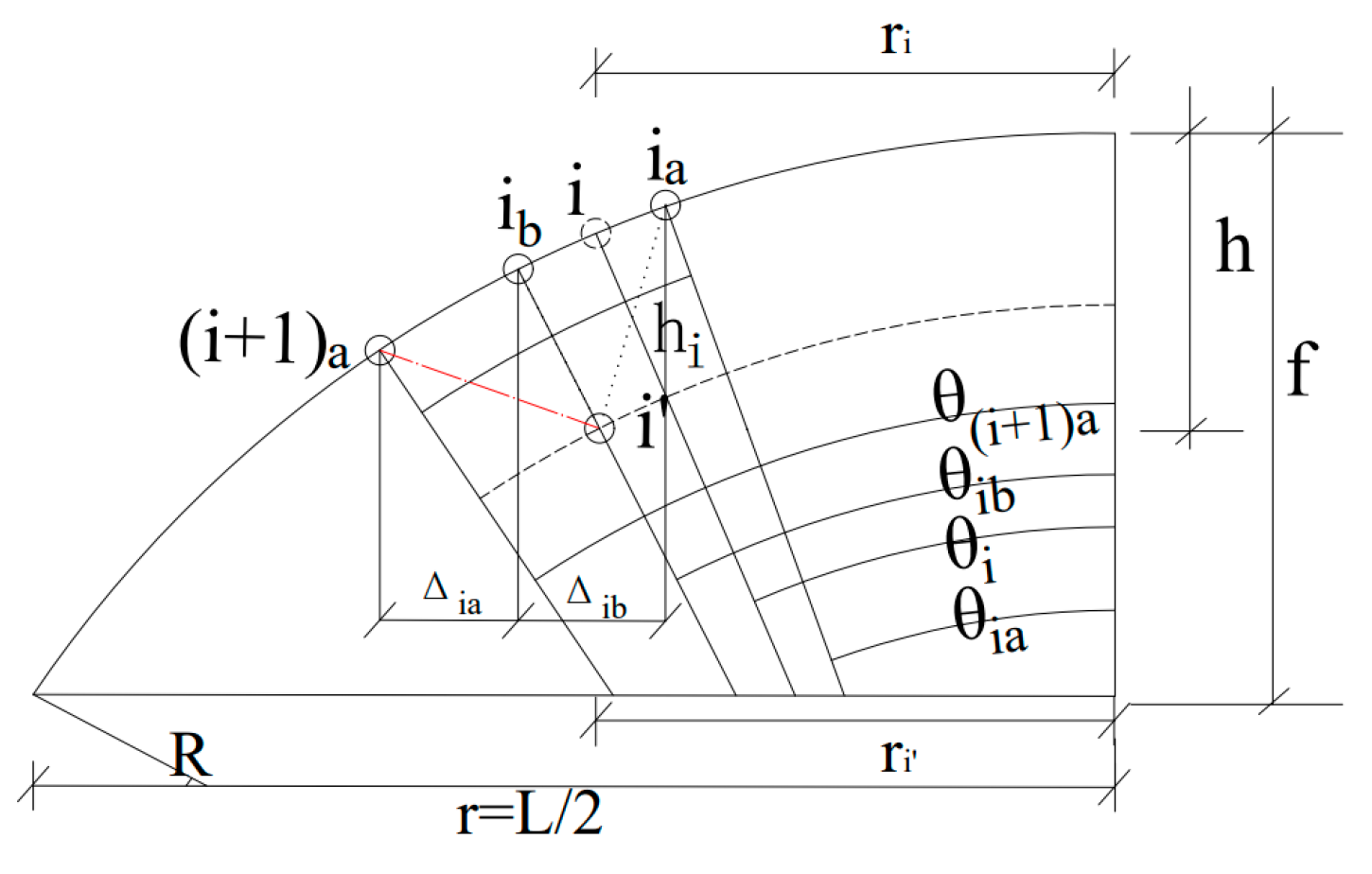
3.3. Main Parameters of the Cable Dome Structure
- (1)
- The span of the cable dome structure is L.
- (2)
- The ratio of the aperture to the span is L1/L.
- (3)
- The ratio of the radial horizontal projection lengths of the front and back sections of the top chord ridge cable is
- (4)
- The structural thickness-to-span ratio is given by , where represents the thickness and is calculated byand in the case of equal thickness, .
- (5)
- The nodal location for node is denoted as and is described by
- (a)
- The mapping point of on the sphere coincides with the point on the sphere, as in programmatic 1.
- (b)
- The mapping point of on the sphere is located at the midpoint of and , with x = 2, as in scheme 2.
- (c)
- The mapping point of on the sphere coincides with , , as in method 2.
4. Example Calculation of a Cable Dome with Rise-to-Span Ratio ≤ 0.11
4.1. When the Radial Lengths of the upper Chord Ridge Cords Are Equal
- (1)
- The rise-to-span ratio and thickness-to-span ratio are important parameters that impact the overall prestress of a cable dome structure. When the rise-to-span ratio increases, there is a decreasing trend in the overall prestress of the structure. Conversely, as the thickness-to-span ratio increases, the prestress of the structure tends to increase.
- (2)
- When the rise-to-span ratio and thickness-to-span ratio of the structure are the same, the prestress values of the same type of cables in the structure are similar. However, as the gap between the two ratios becomes larger, the magnitude of prestress between the same type of cables also increases.
- (3)
- The internal forces in the rods of the inner ring of the cable dome are relatively small. However, as the number of cables in the outer ring increases, the internal forces in the rods of the inner ring also increase.
4.2. When the Radial Chord Lengths (Arc Lengths) of the upper Chord Ridge Cords Are Equal
- (1)
- The internal forces in the inner ring of the structure with an equal chord length arrangement are small. However, their magnitudes increase gradually from the inner ring to the outer ring.
- (2)
- When the rise-to-span ratio and thickness-to-span ratio are kept equal, the differences in prestress magnitudes within the structure are not significant. However, there is a decreasing trend in prestress magnitudes as both the rise-to-span ratio and thickness-to-span ratio increase. This suggests that the rise-to-span ratio has a greater influence on the structure compared to the thickness-to-span ratio.
- (3)
- The calculation results show that the internal forces of the braces are relatively small. In this structure, the primary load-bearing mechanism is based on the tension of the cables, with the braces providing additional support through compression.
5. Example Calculation of a Cable Dome with Rise-to-Span Ratio ≥ 0.12
5.1. Comparison of Radial Horizontal and Radial Chord Length Projected Lengths of the upper Chord Ridge Cord of the Drum-Shaped Honeycomb Quad-Strut Dome
5.2. Calculation and Analysis of Large Rise-to-Span Ratio and Thickness-to-Span Ratio
6. Conclusions
- (1)
- According to the geometric shape of the structure, the cable dome can be categorized into two types: flat spherical cable dome and small hemispherical cable dome. The dividing line between these two types can be determined by setting the spherical rise-to-span ratio equal to 0.11.
- (2)
- The drum-shaped honeycomb quad-strut cable dome can be constructed using two different laying methods based on the upper chord ridge cable. The first method involves laying the upper chord ridge cable according to the radial horizontal projection length, which is equivalent to the thickness-to-span ratio measured vertically on the spherical surface. The second method involves laying the upper chord ridge cable according to the radial chord length (arc length), which is equivalent to the thickness-to-span ratio measured along the normal direction of the spherical surface. Both laying methods can be used to construct the topology and shape of the cable dome.
- (3)
- There are two different topologies for the drum-shaped honeycomb quad-strut cable domes. However, when analyzing the nodal equilibrium equations and the prestressing state of the structure, the formulas remain the same. The only difference lies in the geometry of the members.
- (4)
- When the structure is a flat spherical cable dome, the calculation results of the two layouts have an error of less than 10%. Therefore, it is more convenient to use the layout with the top chord ridge cable laid according to the radial horizontal projection length for calculation purposes.
- (5)
- When the vertical configuration of the structure is a small hemisphere, the two laying methods result in a significant calculation error. Therefore, it is more reasonable to use the laying method where the upper chord ridge cable is laid based on the radial chord length (arc length) being equal.
Author Contributions
Funding
Data Availability Statement
Conflicts of Interest
Appendix A
| Lengths | Angles |
|---|---|
| 0.06 | 0.07 | 0.08 | ||||||||||
| 0.06 | 0.07 | 0.08 | 0.09 | 0.06 | 0.07 | 0.08 | 0.09 | 0.06 | 0.07 | 0.08 | 0.09 | |
| 1.000 | 1.000 | 1.000 | 1.000 | 1.000 | 1.000 | 1.000 | 1.000 | 1.000 | 1.000 | 1.000 | 1.000 | |
| 0.240 | 0.345 | 0.453 | 0.564 | 0.155 | 0.238 | 0.326 | 0.417 | 0.096 | 0.162 | 0.234 | 0.311 | |
| 0.261 | 0.374 | 0.491 | 0.612 | 0.168 | 0.258 | 0.353 | 0.452 | 0.104 | 0.176 | 0.254 | 0.337 | |
| 0.052 | 0.076 | 0.100 | 0.126 | 0.033 | 0.052 | 0.072 | 0.092 | 0.021 | 0.035 | 0.051 | 0.068 | |
| 0.100 | 0.143 | 0.188 | 0.234 | 0.064 | 0.099 | 0.135 | 0.173 | 0.040 | 0.067 | 0.097 | 0.129 | |
| 0.109 | 0.157 | 0.208 | 0.260 | 0.069 | 0.108 | 0.148 | 0.191 | 0.043 | 0.073 | 0.106 | 0.142 | |
| −0.005 | −0.007 | −0.010 | −0.012 | −0.004 | −0.006 | −0.008 | −0.010 | −0.003 | −0.005 | −0.007 | −0.009 | |
| −0.006 | −0.008 | −0.010 | −0.012 | −0.005 | −0.007 | −0.009 | −0.011 | −0.003 | −0.005 | −0.007 | −0.009 | |
| 0.027 | 0.033 | 0.039 | 0.044 | 0.021 | 0.027 | 0.033 | 0.038 | 0.015 | 0.022 | 0.027 | 0.033 | |
| 0.054 | 0.064 | 0.072 | 0.079 | 0.042 | 0.053 | 0.062 | 0.070 | 0.031 | 0.043 | 0.052 | 0.061 | |
| 0.113 | 0.158 | 0.204 | 0.251 | 0.075 | 0.112 | 0.150 | 0.189 | 0.048 | 0.079 | 0.111 | 0.144 | |
| 0.163 | 0.231 | 0.302 | 0.374 | 0.106 | 0.161 | 0.219 | 0.279 | 0.067 | 0.111 | 0.159 | 0.210 | |
| 0.166 | 0.231 | 0.299 | 0.367 | 0.110 | 0.164 | 0.220 | 0.277 | 0.071 | 0.115 | 0.162 | 0.211 | |
| 0.198 | 0.281 | 0.366 | 0.453 | 0.130 | 0.197 | 0.267 | 0.339 | 0.083 | 0.137 | 0.195 | 0.256 | |
| −0.020 | −0.027 | −0.034 | −0.042 | −0.015 | −0.022 | −0.030 | −0.037 | −0.011 | −0.018 | −0.025 | −0.032 | |
| −0.018 | −0.022 | −0.027 | −0.031 | −0.013 | −0.018 | −0.023 | −0.027 | −0.010 | −0.014 | −0.019 | −0.023 | |
| 0.100 | 0.115 | 0.128 | 0.140 | 0.083 | 0.100 | 0.115 | 0.127 | 0.066 | 0.085 | 0.101 | 0.114 | |
| 0.214 | 0.241 | 0.260 | 0.275 | 0.181 | 0.213 | 0.236 | 0.254 | 0.145 | 0.183 | 0.211 | 0.232 | |
| 0.390 | 0.517 | 0.643 | 0.769 | 0.279 | 0.388 | 0.496 | 0.604 | 0.194 | 0.290 | 0.385 | 0.480 | |
| 0.542 | 0.733 | 0.927 | 1.123 | 0.378 | 0.539 | 0.703 | 0.868 | 0.258 | 0.395 | 0.536 | 0.679 | |
| 0.419 | 0.552 | 0.685 | 0.817 | 0.301 | 0.417 | 0.532 | 0.646 | 0.212 | 0.314 | 0.415 | 0.516 | |
| 0.532 | 0.716 | 0.902 | 1.088 | 0.375 | 0.531 | 0.689 | 0.848 | 0.258 | 0.393 | 0.530 | 0.669 | |
| −0.081 | −0.102 | −0.121 | −0.140 | −0.068 | −0.089 | −0.110 | −0.129 | −0.055 | −0.077 | −0.098 | −0.118 | |
| −0.075 | −0.090 | −0.103 | −0.114 | −0.062 | −0.077 | −0.091 | −0.103 | −0.048 | −0.065 | −0.079 | −0.092 | |
| 0.464 | 0.476 | 0.489 | 0.503 | 0.456 | 0.468 | 0.480 | 0.493 | 0.449 | 0.460 | 0.472 | 0.484 | |
| 0.09 | 0.10 | 0.11 | ||||||||||
| 0.09 | 0.010 | 0.11 | 0.12 | 0.09 | 0.010 | 0.11 | 0.12 | 0.09 | 0.010 | 0.11 | 0.12 | |
| 1.000 | 1.000 | 1.000 | 1.000 | 1.000 | 1.000 | 1.000 | 1.000 | 1.000 | 1.000 | 1.000 | 1.000 | |
| 0.231 | 0.298 | 0.367 | 0.437 | 0.170 | 0.227 | 0.286 | 0.347 | 0.123 | 0.171 | 0.222 | 0.275 | |
| 0.250 | 0.323 | 0.398 | 0.474 | 0.184 | 0.246 | 0.310 | 0.377 | 0.133 | 0.186 | 0.241 | 0.299 | |
| 0.050 | 0.065 | 0.081 | 0.097 | 0.037 | 0.050 | 0.063 | 0.077 | 0.027 | 0.037 | 0.049 | 0.061 | |
| 0.096 | 0.124 | 0.152 | 0.182 | 0.071 | 0.094 | 0.119 | 0.144 | 0.051 | 0.071 | 0.092 | 0.115 | |
| 0.105 | 0.136 | 0.168 | 0.201 | 0.077 | 0.103 | 0.131 | 0.159 | 0.055 | 0.078 | 0.101 | 0.126 | |
| −0.007 | −0.009 | −0.011 | −0.014 | −0.006 | −0.008 | −0.010 | −0.012 | −0.005 | −0.007 | −0.008 | −0.010 | |
| −0.007 | −0.009 | −0.011 | −0.013 | −0.006 | −0.008 | −0.010 | −0.011 | −0.005 | −0.006 | −0.008 | −0.010 | |
| 0.028 | 0.033 | 0.037 | 0.042 | 0.023 | 0.028 | 0.033 | 0.037 | 0.019 | 0.023 | 0.028 | 0.033 | |
| 0.052 | 0.059 | 0.065 | 0.070 | 0.043 | 0.051 | 0.058 | 0.063 | 0.035 | 0.043 | 0.050 | 0.056 | |
| 0.109 | 0.139 | 0.168 | 0.198 | 0.083 | 0.108 | 0.134 | 0.160 | 0.061 | 0.083 | 0.106 | 0.130 | |
| 0.157 | 0.202 | 0.247 | 0.294 | 0.117 | 0.155 | 0.195 | 0.235 | 0.086 | 0.119 | 0.153 | 0.188 | |
| 0.160 | 0.203 | 0.247 | 0.291 | 0.121 | 0.158 | 0.197 | 0.236 | 0.090 | 0.122 | 0.156 | 0.190 | |
| 0.193 | 0.247 | 0.302 | 0.359 | 0.145 | 0.191 | 0.239 | 0.288 | 0.107 | 0.147 | 0.189 | 0.232 | |
| −0.027 | −0.034 | −0.041 | −0.048 | −0.023 | −0.029 | −0.036 | −0.043 | −0.019 | −0.025 | −0.032 | −0.038 | |
| −0.020 | −0.024 | −0.028 | −0.032 | −0.016 | −0.020 | −0.024 | −0.028 | −0.013 | −0.017 | −0.021 | −0.025 | |
| 0.101 | 0.114 | 0.125 | 0.136 | 0.089 | 0.102 | 0.114 | 0.125 | 0.076 | 0.090 | 0.102 | 0.114 | |
| 0.209 | 0.228 | 0.242 | 0.255 | 0.185 | 0.206 | 0.224 | 0.237 | 0.161 | 0.185 | 0.204 | 0.220 | |
| 0.383 | 0.467 | 0.551 | 0.634 | 0.304 | 0.380 | 0.455 | 0.531 | 0.239 | 0.308 | 0.376 | 0.445 | |
| 0.532 | 0.659 | 0.788 | 0.917 | 0.415 | 0.528 | 0.642 | 0.758 | 0.321 | 0.421 | 0.524 | 0.627 | |
| 0.414 | 0.503 | 0.592 | 0.680 | 0.330 | 0.411 | 0.492 | 0.572 | 0.261 | 0.335 | 0.409 | 0.482 | |
| 0.529 | 0.652 | 0.777 | 0.902 | 0.417 | 0.528 | 0.639 | 0.752 | 0.325 | 0.425 | 0.526 | 0.628 | |
| −0.106 | −0.126 | −0.146 | −0.166 | −0.094 | −0.114 | −0.134 | −0.154 | −0.081 | −0.102 | −0.123 | −0.143 | |
| −0.082 | −0.094 | −0.106 | −0.118 | −0.071 | −0.084 | −0.097 | −0.108 | −0.061 | −0.074 | −0.087 | −0.099 | |
| 0.476 | 0.489 | 0.503 | 0.518 | 0.468 | 0.480 | 0.494 | 0.508 | 0.461 | 0.472 | 0.485 | 0.499 | |
| 0.12 | 0.14 | 0.16 | ||||||||||
| 0.12 | 0.14 | 0.16 | 0.18 | 0.14 | 0.16 | 0.18 | 0.20 | 0.14 | 0.16 | 0.18 | 0.20 | |
| 1.000 | 1.000 | 1.000 | 1.000 | 1.000 | 1.000 | 1.000 | 1.000 | 1.000 | 1.000 | 1.000 | 1.000 | |
| 0.239 | 0.342 | 0.450 | 0.560 | 0.235 | 0.323 | 0.413 | 0.506 | 0.231 | 0.307 | 0.385 | 0.464 | |
| 0.259 | 0.371 | 0.487 | 0.607 | 0.255 | 0.350 | 0.448 | 0.548 | 0.251 | 0.332 | 0.417 | 0.503 | |
| 0.052 | 0.075 | 0.100 | 0.125 | 0.051 | 0.071 | 0.091 | 0.113 | 0.051 | 0.067 | 0.085 | 0.103 | |
| 0.099 | 0.142 | 0.187 | 0.233 | 0.098 | 0.134 | 0.172 | 0.211 | 0.096 | 0.128 | 0.160 | 0.194 | |
| 0.109 | 0.157 | 0.208 | 0.260 | 0.108 | 0.149 | 0.192 | 0.236 | 0.107 | 0.142 | 0.179 | 0.217 | |
| −0.010 | −0.014 | −0.018 | −0.022 | −0.011 | −0.015 | −0.019 | −0.023 | −0.012 | −0.016 | −0.020 | −0.024 | |
| −0.009 | −0.012 | −0.016 | −0.020 | −0.010 | −0.013 | −0.017 | −0.020 | −0.010 | −0.014 | −0.017 | −0.020 | |
| 0.029 | 0.038 | 0.046 | 0.054 | 0.030 | 0.038 | 0.046 | 0.054 | 0.031 | 0.038 | 0.046 | 0.053 | |
| 0.050 | 0.060 | 0.068 | 0.074 | 0.048 | 0.057 | 0.064 | 0.069 | 0.047 | 0.054 | 0.060 | 0.065 | |
| 0.111 | 0.155 | 0.201 | 0.246 | 0.109 | 0.147 | 0.185 | 0.224 | 0.107 | 0.139 | 0.172 | 0.206 | |
| 0.159 | 0.226 | 0.295 | 0.366 | 0.156 | 0.212 | 0.271 | 0.331 | 0.153 | 0.201 | 0.252 | 0.303 | |
| 0.165 | 0.231 | 0.299 | 0.367 | 0.164 | 0.220 | 0.277 | 0.336 | 0.162 | 0.211 | 0.260 | 0.311 | |
| 0.199 | 0.282 | 0.368 | 0.456 | 0.198 | 0.269 | 0.342 | 0.417 | 0.196 | 0.258 | 0.322 | 0.387 | |
| −0.035 | −0.049 | −0.063 | −0.077 | −0.040 | −0.053 | −0.067 | −0.081 | −0.044 | −0.057 | −0.070 | −0.084 | |
| −0.022 | −0.030 | −0.038 | −0.046 | −0.024 | −0.032 | −0.040 | −0.048 | −0.026 | −0.034 | −0.041 | −0.049 | |
| 0.105 | 0.127 | 0.147 | 0.168 | 0.107 | 0.128 | 0.148 | 0.168 | 0.108 | 0.128 | 0.148 | 0.168 | |
| 0.203 | 0.229 | 0.248 | 0.263 | 0.198 | 0.220 | 0.238 | 0.251 | 0.191 | 0.211 | 0.227 | 0.240 | |
| 0.375 | 0.499 | 0.622 | 0.745 | 0.368 | 0.473 | 0.578 | 0.682 | 0.360 | 0.451 | 0.541 | 0.632 | |
| 0.511 | 0.695 | 0.882 | 1.070 | 0.497 | 0.653 | 0.810 | 0.969 | 0.482 | 0.616 | 0.751 | 0.887 | |
| 0.418 | 0.554 | 0.688 | 0.822 | 0.416 | 0.533 | 0.649 | 0.765 | 0.414 | 0.517 | 0.619 | 0.721 | |
| 0.529 | 0.715 | 0.903 | 1.093 | 0.527 | 0.688 | 0.851 | 1.014 | 0.525 | 0.667 | 0.811 | 0.955 | |
| −0.133 | −0.173 | −0.213 | −0.252 | −0.150 | −0.190 | −0.229 | −0.268 | −0.166 | −0.206 | −0.245 | −0.284 | |
| −0.089 | −0.112 | −0.134 | −0.157 | −0.095 | −0.118 | −0.141 | −0.164 | −0.101 | −0.125 | −0.148 | −0.172 | |
| 0.488 | 0.519 | 0.555 | 0.594 | 0.499 | 0.532 | 0.570 | 0.611 | 0.511 | 0.546 | 0.585 | 0.628 | |
| 0.12 | 0.14 | 0.16 | ||||||||||
| 0.12 | 0.14 | 0.16 | 0.18 | 0.14 | 0.16 | 0.18 | 0.20 | 0.14 | 0.16 | 0.18 | 0.20 | |
| 1.000 | 1.000 | 1.000 | 1.000 | 1.000 | 1.000 | 1.000 | 1.000 | 1.000 | 1.000 | 1.000 | 1.000 | |
| 0.218 | 0.315 | 0.416 | 0.521 | 0.207 | 0.288 | 0.372 | 0.458 | 0.196 | 0.264 | 0.334 | 0.406 | |
| 0.236 | 0.342 | 0.452 | 0.565 | 0.225 | 0.312 | 0.403 | 0.496 | 0.213 | 0.286 | 0.362 | 0.440 | |
| 0.048 | 0.070 | 0.093 | 0.117 | 0.046 | 0.064 | 0.083 | 0.102 | 0.043 | 0.058 | 0.074 | 0.091 | |
| 0.091 | 0.131 | 0.173 | 0.217 | 0.086 | 0.120 | 0.155 | 0.191 | 0.082 | 0.110 | 0.139 | 0.170 | |
| 0.099 | 0.145 | 0.193 | 0.242 | 0.095 | 0.133 | 0.172 | 0.213 | 0.090 | 0.122 | 0.156 | 0.190 | |
| −0.009 | −0.013 | −0.017 | −0.022 | −0.010 | −0.014 | −0.018 | −0.022 | −0.011 | −0.014 | −0.018 | −0.022 | |
| −0.008 | −0.012 | −0.015 | −0.019 | −0.009 | −0.012 | −0.016 | −0.019 | −0.009 | −0.012 | −0.016 | −0.019 | |
| 0.028 | 0.037 | 0.045 | 0.053 | 0.029 | 0.036 | 0.044 | 0.052 | 0.029 | 0.036 | 0.043 | 0.050 | |
| 0.049 | 0.059 | 0.067 | 0.074 | 0.047 | 0.056 | 0.063 | 0.069 | 0.045 | 0.053 | 0.059 | 0.064 | |
| 0.104 | 0.147 | 0.191 | 0.235 | 0.100 | 0.136 | 0.172 | 0.209 | 0.095 | 0.126 | 0.157 | 0.188 | |
| 0.150 | 0.216 | 0.283 | 0.353 | 0.145 | 0.199 | 0.256 | 0.314 | 0.138 | 0.185 | 0.233 | 0.282 | |
| 0.154 | 0.217 | 0.281 | 0.347 | 0.148 | 0.201 | 0.255 | 0.310 | 0.142 | 0.187 | 0.233 | 0.280 | |
| 0.186 | 0.266 | 0.349 | 0.433 | 0.180 | 0.248 | 0.317 | 0.388 | 0.174 | 0.231 | 0.291 | 0.352 | |
| −0.034 | −0.047 | −0.061 | −0.075 | −0.037 | −0.050 | −0.064 | −0.077 | −0.040 | −0.053 | −0.066 | −0.079 | |
| −0.022 | −0.029 | −0.037 | −0.045 | −0.023 | −0.030 | −0.038 | −0.045 | −0.024 | −0.031 | −0.038 | −0.046 | |
| 0.103 | 0.124 | 0.145 | 0.165 | 0.103 | 0.124 | 0.144 | 0.163 | 0.103 | 0.123 | 0.142 | 0.162 | |
| 0.201 | 0.228 | 0.247 | 0.262 | 0.195 | 0.218 | 0.236 | 0.250 | 0.188 | 0.209 | 0.225 | 0.238 | |
| 0.373 | 0.498 | 0.622 | 0.746 | 0.365 | 0.472 | 0.577 | 0.683 | 0.356 | 0.449 | 0.541 | 0.632 | |
| 0.519 | 0.709 | 0.903 | 1.099 | 0.508 | 0.671 | 0.836 | 1.003 | 0.495 | 0.637 | 0.781 | 0.927 | |
| 0.406 | 0.541 | 0.674 | 0.806 | 0.401 | 0.516 | 0.630 | 0.744 | 0.394 | 0.495 | 0.595 | 0.695 | |
| 0.524 | 0.713 | 0.904 | 1.096 | 0.521 | 0.684 | 0.849 | 1.016 | 0.516 | 0.661 | 0.807 | 0.955 | |
| −0.131 | −0.170 | −0.209 | −0.248 | −0.146 | −0.185 | −0.224 | −0.262 | −0.160 | −0.199 | −0.237 | −0.275 | |
| −0.090 | −0.113 | −0.136 | −0.159 | −0.096 | −0.119 | −0.142 | −0.166 | −0.102 | −0.126 | −0.149 | −0.173 | |
| 0.490 | 0.520 | 0.555 | 0.594 | 0.501 | 0.533 | 0.569 | 0.609 | 0.512 | 0.545 | 0.583 | 0.625 | |
References
- Zhang, A.; Liu, T.; Zhang, Y.; Liu, X. Research prospect of rapid full-assembly long-span prestressed space steel structure system based on intelligent construction. Beijing Ind. News 2020, 46, 591–603. [Google Scholar]
- Buckminster, F.R. Tensile-Integrity Structures. U.S. Patent 3,063,521, 13 November 1962. [Google Scholar]
- Geiger, D.H.; Stefaniuk, A.; Chen, D. The Design and Construction of Two Cable Domes for the Korean Olympics. In Proceedings of the IASS Symposium on Shells, Membranes and Space Frames, Osaka, Japan, 15–19 September 1986; Elsevier Science Publishers BV: Amsterdam, The Netherlands, 1986. [Google Scholar]
- Feng, Y.; Xiang, X.; Dong, S.; Qiu, T.; Zhang, X.D. Design and research on tensegrity type cable dome with metal roof of Ya’an Tianquan Gymnasium. Spat. Struct. 2019, 25, 3–13. (In Chinese) [Google Scholar]
- Zhang, A.; Wu, C.; Zhang, Y. Calculation method and parameter analysis of T-shaped three-pole cable dome prestress. J. Beijing Univ. Civ. Eng. Archit. 2021, 37, 1–7. [Google Scholar]
- Zhang, W.; He, J. Experimental study on static performance of Geiger-type cable dome structural model. Build. Struct. 2018, 48, 108–112. [Google Scholar]
- Zhang, A.; Zhu, L.; Zhang, Y.; Wen, W.; Lin, H. Analysis method of star tetrahedral cable dome configuration and prestress. Vib. Shock 2021, 40, 84–91. [Google Scholar]
- Zhang, A.; Yuan, W.; Zhang, Y.; Julina, Z.; Xiong, J. Analysis of static performance of single and double strut staggered cable dome structure. Vib. Shock 2022, 41, 321–330. [Google Scholar]
- Chen, L.; Li, Z.; Liu, Y.; Huang, K.; Zeng, Y.; Zhou, Y.; Dong, S. Analysis and Evaluation of the Progressive Collapse Behaviour of a Cable Dome Structure. Buildings 2022, 12, 1700. [Google Scholar] [CrossRef]
- Zhang, N.; Luo, B.; Zhao, M.; Ruan, Y.; Chou, R. Research and application of key technology for structural molding of large-opening rigid internal tension ring cable domes. J. Build. Struct. 2023, 44, 150–157+215. [Google Scholar]
- Dong, S.; Zheng, X.; Tu, Y. Simple calculation method of configuration and prestress state of honeycomb single-pole cable dome. Prog. Build. Steel Struct. 2020, 22, 1–9. [Google Scholar]
- Dong, S.; Zhu, X.; Tu, Y. Simple calculation method and parameter sensitivity analysis of configuration and prestress state of honeycomb double-brace cable dome. J. Build. Struct. 2019, 40, 128–135. [Google Scholar]
- Yuan, X.; Zhang, P. Research on parameterized conformation of hybrid cable dome structure. J. Huazhong Univ. Sci. Technol. 2024, 52, 126–132. [Google Scholar] [CrossRef]
- Weigang, C.; Yuan, T. Analysis of structural configuration and prestress state of honeycomb three-pole cable dome. Eng. Mech. 2019, 36, 128–135. [Google Scholar]
- Dong, S.; Yuan, T. Configuration and prestress analysis method of honeycomb four-pole cable dome. Spat. Struct. 2018, 24, 3–12. [Google Scholar]
- Dong, S.; Chen, W.; Tu, Y.; Zhen, X. Prestress and multi-parameter sensitivity analysis of sunflower double-brace cable dome. J. Tongji Univ. 2019, 47, 739–746, 801. [Google Scholar]
- Dong, S.; Liu, H.; Zhu, X. Determination of prestress state, parameter analysis and trial design of sunflower three-pole type II. cable dome structure. J. Build. Struct. 2021, 42, 1–17. [Google Scholar]
- Liu, T.; Zhang, A.; Li, J. Research on prestress distribution and structural performance of large-span assembled ridge pole ring braced cable dome. Eng. Mech. 2023. [Google Scholar] [CrossRef]
- Dong, S.; Yida, W.; Hongchuang, L. Innovative study on multi-pole cable dome structure system and prestress state analysis of drum honeycomb sequence. Spat. Struct. 2022, 28, 3–15. [Google Scholar]
- Dong, S.; Hui, L.; Zhaoquan, C. Analysis of structural configuration and prestress state of drum honeycomb four-pole cable dome. Spat. Struct. 2019, 28, 3–15. [Google Scholar]
- Zhang, H.; Lv, H.; Zhu, Z.; Chen, Z.; Chu, Y. Study on the Dynamic Response of the Component Failure of Drum-Shaped Honeycomb-Type III Cable Dome with Quad-Strut Layout. Buildings 2023, 13, 1894. [Google Scholar] [CrossRef]
- Hui, L.; Yiyi, C.; Dong, S. Static performance analysis of large open drum honeycomb four-pole cable dome. Spat. Struct. 2023, 29, 3–11. [Google Scholar] [CrossRef]
- Krishna, P.; Godbole, P.N. Cable-Suspended Roofs, 2nd ed.; McGraw Hill Education: New Delhi, India, 2013. [Google Scholar]
- Levy, M.P. The Georgia Dome and beyond: Achieving lightweight-long span structures. In Spatial, Lattice and Tension Structures; ASCE: Reston, VI, USA, 1994; pp. 560–562. [Google Scholar]
- Levy, M.; Jing, T.F.; Brzozowski, A.; Freeman, G. Estadio Ciudad de La Plata (La Plata Stadium), Argentina. Struct. Eng. Int. 2013, 23, 303–310. [Google Scholar] [CrossRef]
- Cheng, Z.; Lou, S.; Yan, X.; Liu, H.; Wang, X. Time-history analysis of wind vibration response for the cable dome of gymnasium at Tianjin University of Technology. Spat. Struct. 2017, 23, 21–29. (In Chinese) [Google Scholar]
- Zhou, Y.-X.; Zhao, Y.; Xiang, X. Investigation on topology optimization of cable dome nodes in Ya’an Tianquan Stadium. Spat. Struct. 2021, 27, 74–80+52. [Google Scholar] [CrossRef]


| Form | |||
|---|---|---|---|
| Node with axis of symmetry | Two in total | Two in total | Two in total |
| Node without axis of symmetry | Two in total | Four in total | Four in total. |
| Nodal equilibrium equations | (2 × 1) + (3 × 2) = 8 | (2 × 2) + (3 × 4) = 16 | (3 × 2) + (3 × 6) = 24 |
| Internal force on the cable stem | 9 in total. | 17 in total. | 25 in total. |
| 0.06 | 0.07 | 0.08 | ||||||||||
| 0.06 | 0.07 | 0.08 | 0.09 | 0.06 | 0.07 | 0.08 | 0.09 | 0.06 | 0.07 | 0.08 | 0.09 | |
| 1.000 | 1.000 | 1.000 | 1.000 | 1.000 | 1.000 | 1.000 | 1.000 | 1.000 | 1.000 | 1.000 | 1.000 | |
| 0.246 | 0.352 | 0.462 | 0.575 | 0.160 | 0.245 | 0.335 | 0.429 | 0.101 | 0.170 | 0.244 | 0.322 | |
| 0.267 | 0.381 | 0.500 | 0.623 | 0.174 | 0.266 | 0.363 | 0.465 | 0.110 | 0.184 | 0.265 | 0.350 | |
| 0.054 | 0.077 | 0.102 | 0.128 | 0.035 | 0.053 | 0.074 | 0.095 | 0.022 | 0.037 | 0.053 | 0.071 | |
| 0.102 | 0.146 | 0.191 | 0.238 | 0.067 | 0.102 | 0.139 | 0.178 | 0.042 | 0.070 | 0.101 | 0.134 | |
| 0.111 | 0.160 | 0.212 | 0.264 | 0.072 | 0.111 | 0.153 | 0.196 | 0.045 | 0.076 | 0.111 | 0.147 | |
| −0.005 | −0.007 | −0.010 | −0.012 | −0.004 | −0.006 | −0.008 | −0.010 | −0.003 | −0.005 | −0.007 | −0.009 | |
| −0.007 | −0.009 | −0.011 | −0.013 | −0.005 | −0.007 | −0.009 | −0.011 | −0.003 | −0.005 | −0.007 | −0.009 | |
| 0.027 | 0.033 | 0.039 | 0.044 | 0.021 | 0.027 | 0.033 | 0.038 | 0.015 | 0.022 | 0.028 | 0.033 | |
| 0.054 | 0.064 | 0.072 | 0.079 | 0.042 | 0.053 | 0.062 | 0.070 | 0.031 | 0.043 | 0.053 | 0.061 | |
| 0.115 | 0.160 | 0.207 | 0.254 | 0.077 | 0.115 | 0.153 | 0.193 | 0.050 | 0.081 | 0.114 | 0.148 | |
| 0.165 | 0.234 | 0.305 | 0.378 | 0.109 | 0.164 | 0.223 | 0.283 | 0.070 | 0.115 | 0.163 | 0.214 | |
| 0.169 | 0.235 | 0.303 | 0.372 | 0.113 | 0.168 | 0.225 | 0.283 | 0.074 | 0.120 | 0.168 | 0.217 | |
| 0.202 | 0.285 | 0.371 | 0.459 | 0.134 | 0.202 | 0.273 | 0.346 | 0.086 | 0.142 | 0.201 | 0.263 | |
| −0.020 | −0.027 | −0.035 | −0.042 | −0.016 | −0.023 | −0.030 | −0.037 | −0.012 | −0.018 | −0.025 | −0.032 | |
| −0.018 | −0.023 | −0.027 | −0.031 | −0.014 | −0.018 | −0.023 | −0.027 | −0.010 | −0.015 | −0.019 | −0.023 | |
| 0.100 | 0.116 | 0.129 | 0.140 | 0.084 | 0.101 | 0.115 | 0.127 | 0.067 | 0.086 | 0.102 | 0.115 | |
| 0.215 | 0.241 | 0.261 | 0.275 | 0.182 | 0.214 | 0.237 | 0.254 | 0.147 | 0.185 | 0.212 | 0.232 | |
| 0.390 | 0.517 | 0.643 | 0.769 | 0.280 | 0.388 | 0.497 | 0.604 | 0.196 | 0.291 | 0.386 | 0.481 | |
| 0.540 | 0.729 | 0.921 | 1.115 | 0.377 | 0.536 | 0.698 | 0.862 | 0.258 | 0.394 | 0.532 | 0.673 | |
| 0.422 | 0.556 | 0.689 | 0.821 | 0.305 | 0.421 | 0.536 | 0.651 | 0.216 | 0.319 | 0.421 | 0.522 | |
| 0.533 | 0.716 | 0.901 | 1.088 | 0.377 | 0.532 | 0.690 | 0.848 | 0.261 | 0.395 | 0.532 | 0.670 | |
| −0.081 | −0.102 | −0.121 | −0.141 | −0.068 | −0.090 | −0.110 | −0.130 | −0.055 | −0.077 | −0.098 | −0.118 | |
| −0.075 | −0.089 | −0.102 | −0.113 | −0.061 | −0.077 | −0.090 | −0.102 | −0.048 | −0.064 | −0.079 | −0.091 | |
| 0.464 | 0.476 | 0.488 | 0.502 | 0.455 | 0.467 | 0.479 | 0.492 | 0.447 | 0.459 | 0.470 | 0.483 | |
| 0.09 | 0.10 | 0.11 | ||||||||||
| 0.09 | 0.010 | 0.11 | 0.12 | 0.09 | 0.010 | 0.11 | 0.12 | 0.09 | 0.010 | 0.11 | 0.12 | |
| 1.000 | 1.000 | 1.000 | 1.000 | 1.000 | 1.000 | 1.000 | 1.000 | 1.000 | 1.000 | 1.000 | 1.000 | |
| 0.243 | 0.312 | 0.384 | 0.457 | 0.182 | 0.242 | 0.304 | 0.367 | 0.135 | 0.186 | 0.240 | 0.296 | |
| 0.263 | 0.338 | 0.416 | 0.495 | 0.198 | 0.262 | 0.329 | 0.398 | 0.147 | 0.202 | 0.260 | 0.321 | |
| 0.053 | 0.069 | 0.085 | 0.101 | 0.039 | 0.053 | 0.067 | 0.081 | 0.029 | 0.040 | 0.052 | 0.065 | |
| 0.101 | 0.130 | 0.159 | 0.190 | 0.076 | 0.100 | 0.126 | 0.153 | 0.056 | 0.077 | 0.100 | 0.123 | |
| 0.110 | 0.143 | 0.176 | 0.210 | 0.082 | 0.110 | 0.139 | 0.169 | 0.061 | 0.085 | 0.110 | 0.136 | |
| −0.007 | −0.010 | −0.012 | −0.014 | −0.006 | −0.008 | −0.010 | −0.012 | −0.005 | −0.007 | −0.009 | −0.011 | |
| −0.008 | −0.009 | −0.011 | −0.013 | −0.006 | −0.008 | −0.010 | −0.012 | −0.005 | −0.007 | −0.008 | −0.010 | |
| 0.028 | 0.033 | 0.038 | 0.042 | 0.024 | 0.029 | 0.033 | 0.038 | 0.019 | 0.024 | 0.029 | 0.033 | |
| 0.052 | 0.059 | 0.065 | 0.070 | 0.044 | 0.052 | 0.058 | 0.063 | 0.036 | 0.044 | 0.051 | 0.057 | |
| 0.113 | 0.143 | 0.173 | 0.204 | 0.087 | 0.113 | 0.139 | 0.166 | 0.065 | 0.088 | 0.112 | 0.136 | |
| 0.162 | 0.207 | 0.254 | 0.301 | 0.122 | 0.161 | 0.201 | 0.243 | 0.091 | 0.125 | 0.160 | 0.196 | |
| 0.167 | 0.211 | 0.256 | 0.302 | 0.128 | 0.167 | 0.206 | 0.246 | 0.097 | 0.131 | 0.166 | 0.202 | |
| 0.201 | 0.256 | 0.312 | 0.370 | 0.153 | 0.200 | 0.250 | 0.300 | 0.115 | 0.156 | 0.200 | 0.245 | |
| −0.028 | −0.035 | −0.042 | −0.049 | −0.024 | −0.030 | −0.037 | −0.044 | −0.019 | −0.026 | −0.033 | −0.040 | |
| −0.020 | −0.024 | −0.028 | −0.032 | −0.017 | −0.021 | −0.025 | −0.029 | −0.014 | −0.018 | −0.022 | −0.026 | |
| 0.102 | 0.115 | 0.126 | 0.137 | 0.090 | 0.103 | 0.115 | 0.126 | 0.078 | 0.092 | 0.104 | 0.116 | |
| 0.210 | 0.229 | 0.243 | 0.255 | 0.187 | 0.208 | 0.225 | 0.238 | 0.163 | 0.187 | 0.206 | 0.221 | |
| 0.384 | 0.467 | 0.551 | 0.634 | 0.306 | 0.381 | 0.456 | 0.531 | 0.242 | 0.310 | 0.378 | 0.446 | |
| 0.528 | 0.652 | 0.778 | 0.905 | 0.413 | 0.523 | 0.634 | 0.746 | 0.320 | 0.418 | 0.517 | 0.618 | |
| 0.420 | 0.510 | 0.600 | 0.689 | 0.338 | 0.420 | 0.501 | 0.581 | 0.269 | 0.344 | 0.419 | 0.493 | |
| 0.531 | 0.654 | 0.778 | 0.902 | 0.421 | 0.530 | 0.641 | 0.753 | 0.330 | 0.430 | 0.530 | 0.631 | |
| −0.107 | −0.127 | −0.147 | −0.167 | −0.095 | −0.116 | −0.136 | −0.156 | −0.083 | −0.104 | −0.124 | −0.145 | |
| −0.081 | −0.093 | −0.105 | −0.116 | −0.070 | −0.083 | −0.095 | −0.107 | −0.060 | −0.073 | −0.086 | −0.098 | |
| 0.474 | 0.487 | 0.502 | 0.517 | 0.466 | 0.479 | 0.492 | 0.507 | 0.459 | 0.470 | 0.483 | 0.498 | |
| Equal distribution of radial horizontal projections | ||||||||
| 0.09 | 20.41° | 1.002 | 1.008 | 1.012 | 1.026 | 1.031 | 1.057 | |
| 0.10 | 22.62° | 1.003 | 1.008 | 1.019 | 1.026 | 1.049 | 1.057 | |
| 0.11 | 24.81° | 1.003 | 1.011 | 1.019 | 1.039 | 1.049 | 1.086 | |
| 0.12 | 26.99° | 1.005 | 1.013 | 1.027 | 1.046 | 1.070 | 1.103 | |
| 0.13 | 29.15° | 1.005 | 1.016 | 1.031 | 1.053 | 1.083 | 1.121 | |
| 0.14 | 31.28° | 1.006 | 1.018 | 1.036 | 1.061 | 1.095 | 1.142 | |
| 0.15 | 33.40° | 1.007 | 1.020 | 1.040 | 1.069 | 1.109 | 1.164 | |
| 0.16 | 35.49° | 1.008 | 1.022 | 1.045 | 1.078 | 1.124 | 1.188 | |
| 0.17 | 37.56° | 1.009 | 1.025 | 1.050 | 1.087 | 1.140 | 1.214 | |
| 0.18 | 39.60° | 1.009 | 1.027 | 1.055 | 1.097 | 1.156 | 1.242 | |
| Radial chords are laid out with equal length | ||||||||
| 0.09 | 20.41° | 1.003 | 1.008 | 1.016 | 1.027 | 1.040 | 1.057 | |
| 0.10 | 22.62° | 1.004 | 1.010 | 1.020 | 1.033 | 1.050 | 1.071 | |
| 0.11 | 24.81° | 1.004 | 1.012 | 1.024 | 1.040 | 1.061 | 1.087 | |
| 0.12 | 26.99° | 1.005 | 1.014 | 1.028 | 1.048 | 1.073 | 1.104 | |
| 0.13 | 29.15° | 1.006 | 1.017 | 1.033 | 1.056 | 1.086 | 1.123 | |
| 0.14 | 31.28° | 1.007 | 1.019 | 1.038 | 1.065 | 1.100 | 1.144 | |
| 0.15 | 33.40° | 1.008 | 1.022 | 1.044 | 1.075 | 1.115 | 1.167 | |
| 0.16 | 35.49° | 1.009 | 1.025 | 1.050 | 1.085 | 1.131 | 1.192 | |
| 0.17 | 37.56° | 1.010 | 1.028 | 1.056 | 1.096 | 1.149 | 1.219 | |
| 0.18 | 39.60° | 1.011 | 1.031 | 1.063 | 1.108 | 1.168 | 1.248 |
Disclaimer/Publisher’s Note: The statements, opinions and data contained in all publications are solely those of the individual author(s) and contributor(s) and not of MDPI and/or the editor(s). MDPI and/or the editor(s) disclaim responsibility for any injury to people or property resulting from any ideas, methods, instructions or products referred to in the content. |
© 2024 by the authors. Licensee MDPI, Basel, Switzerland. This article is an open access article distributed under the terms and conditions of the Creative Commons Attribution (CC BY) license (https://creativecommons.org/licenses/by/4.0/).
Share and Cite
Lv, H.; Chen, Z.; Dong, S.; Zhu, Z.; Xie, X.; Zhong, Y. Analytical Study of Structural Conformation and Prestressing State of Drum-Shaped Honeycomb Quad-Strut Cable Dome Structure with Different Calculation Methods. Buildings 2024, 14, 179. https://doi.org/10.3390/buildings14010179
Lv H, Chen Z, Dong S, Zhu Z, Xie X, Zhong Y. Analytical Study of Structural Conformation and Prestressing State of Drum-Shaped Honeycomb Quad-Strut Cable Dome Structure with Different Calculation Methods. Buildings. 2024; 14(1):179. https://doi.org/10.3390/buildings14010179
Chicago/Turabian StyleLv, Hui, Zhaoquan Chen, Shilin Dong, Zhongyi Zhu, Xin Xie, and Yanfen Zhong. 2024. "Analytical Study of Structural Conformation and Prestressing State of Drum-Shaped Honeycomb Quad-Strut Cable Dome Structure with Different Calculation Methods" Buildings 14, no. 1: 179. https://doi.org/10.3390/buildings14010179
APA StyleLv, H., Chen, Z., Dong, S., Zhu, Z., Xie, X., & Zhong, Y. (2024). Analytical Study of Structural Conformation and Prestressing State of Drum-Shaped Honeycomb Quad-Strut Cable Dome Structure with Different Calculation Methods. Buildings, 14(1), 179. https://doi.org/10.3390/buildings14010179