
Rotational Stiffness Investigation and Parametric Analysis of a Novel Assembled Joint in Lattice Shells


Abstract
1. Introduction
2. Experimental Program
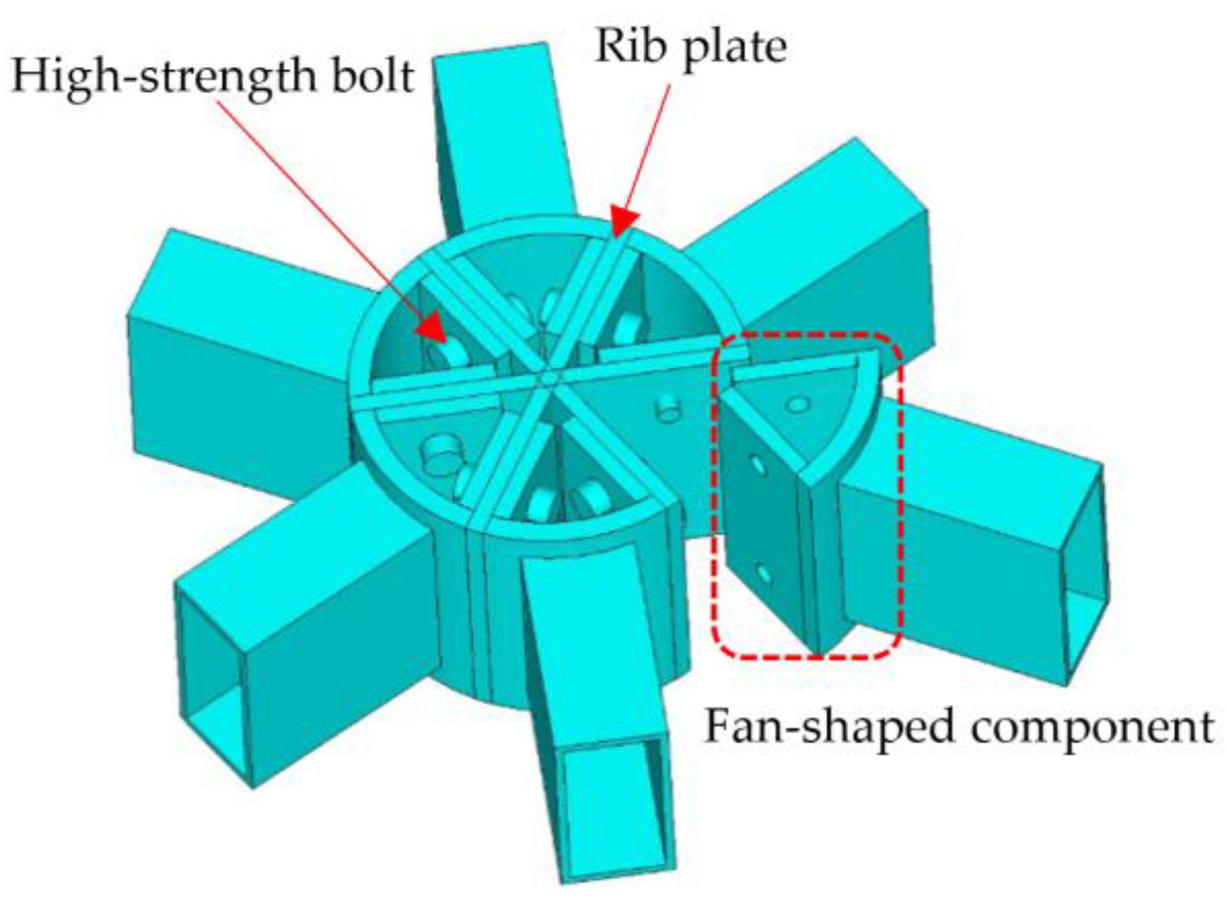
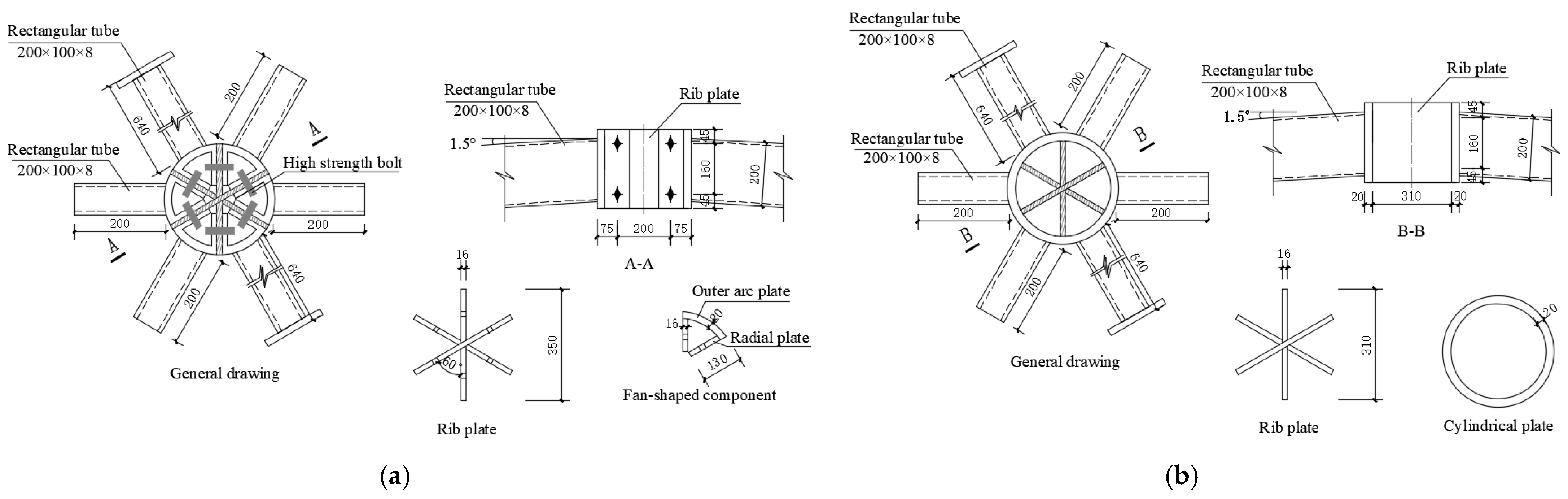
2.1. Specimens
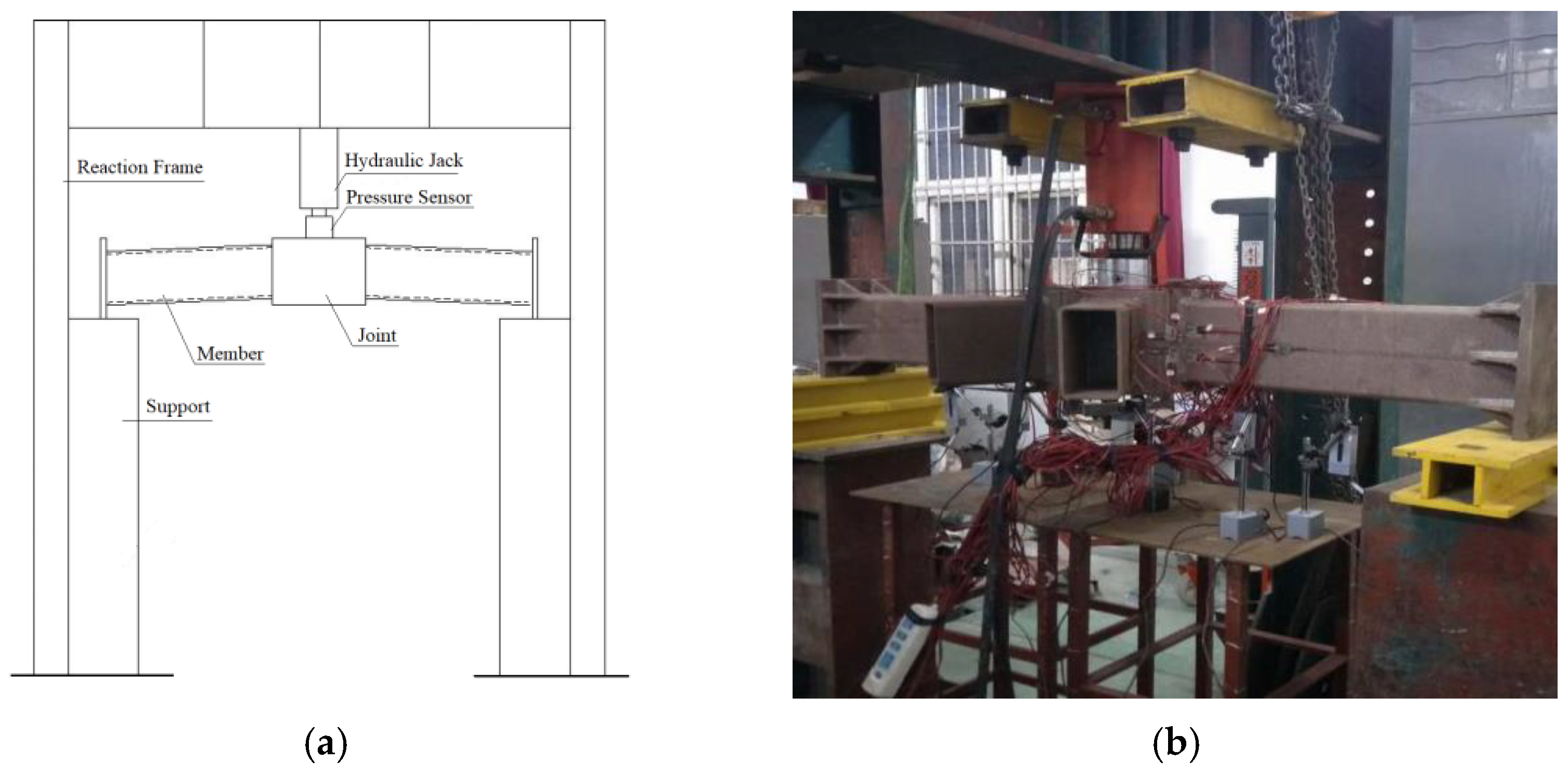
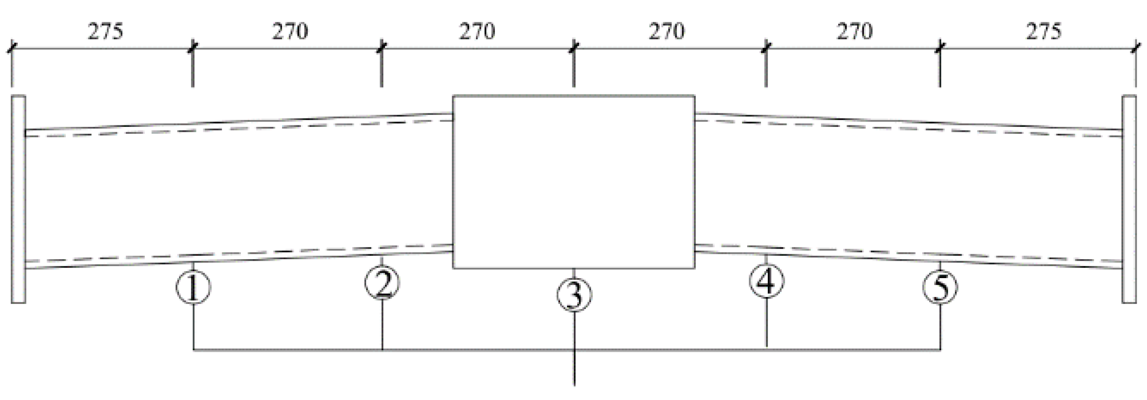
2.2. Experimental Loading and Measurement Scheme
3. Experimental Results and Analysis
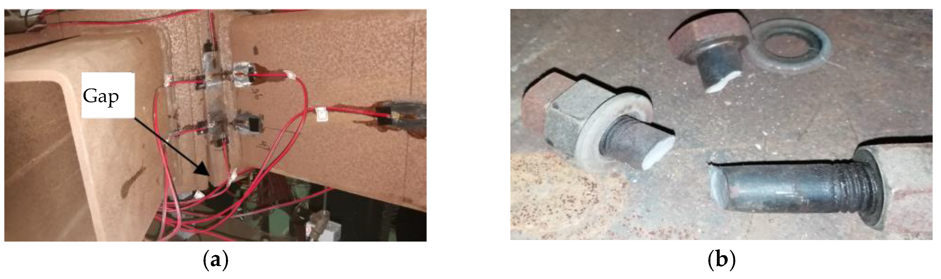
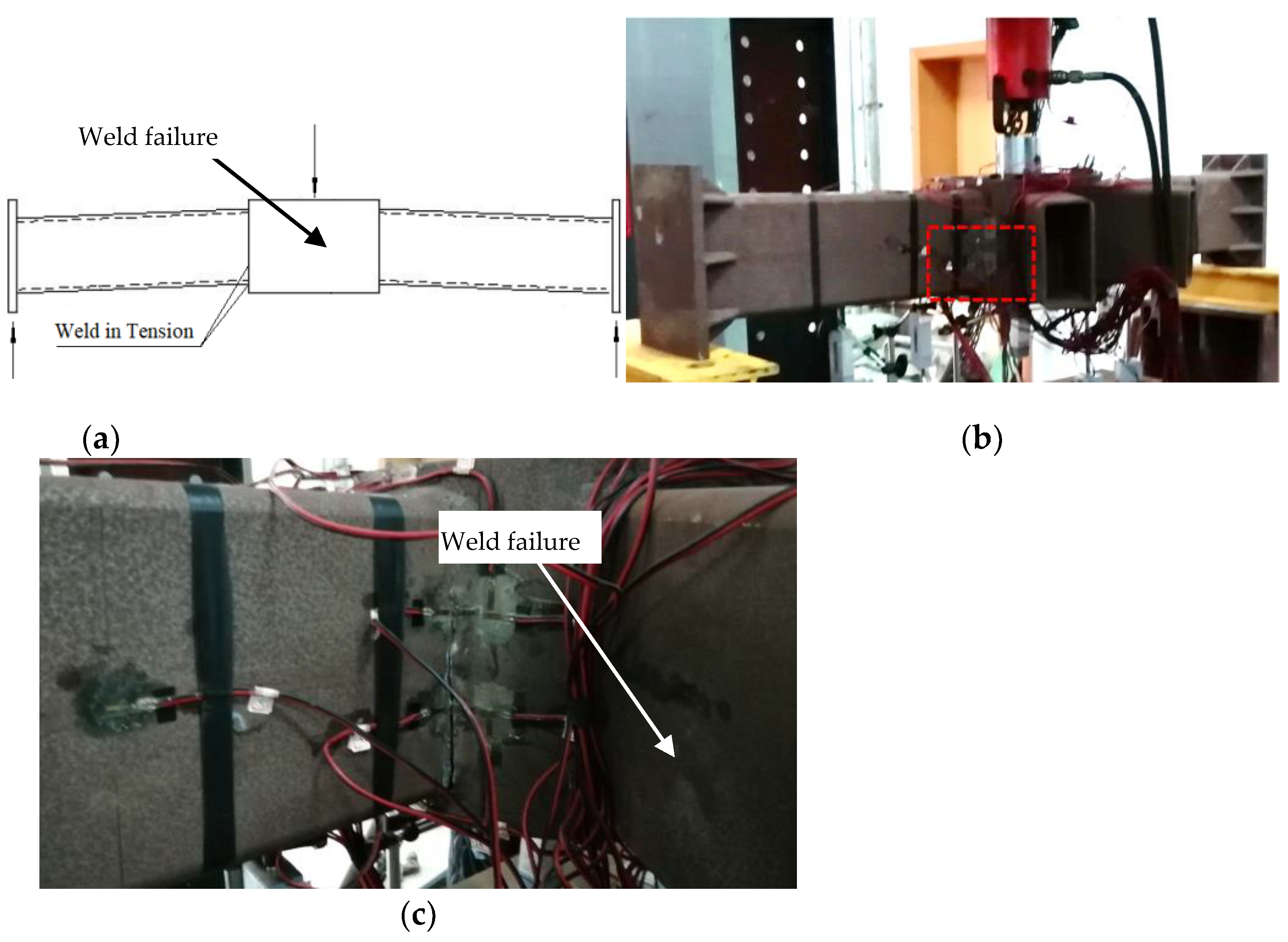
3.1. Experimental Phenomena
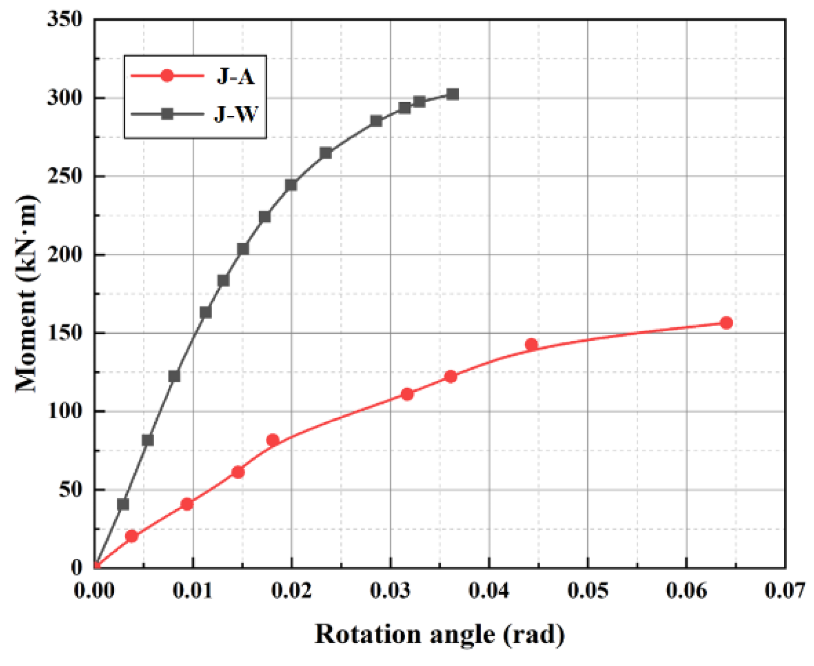
3.2. Moment–Rotation Curve
4. Verification of FE Models
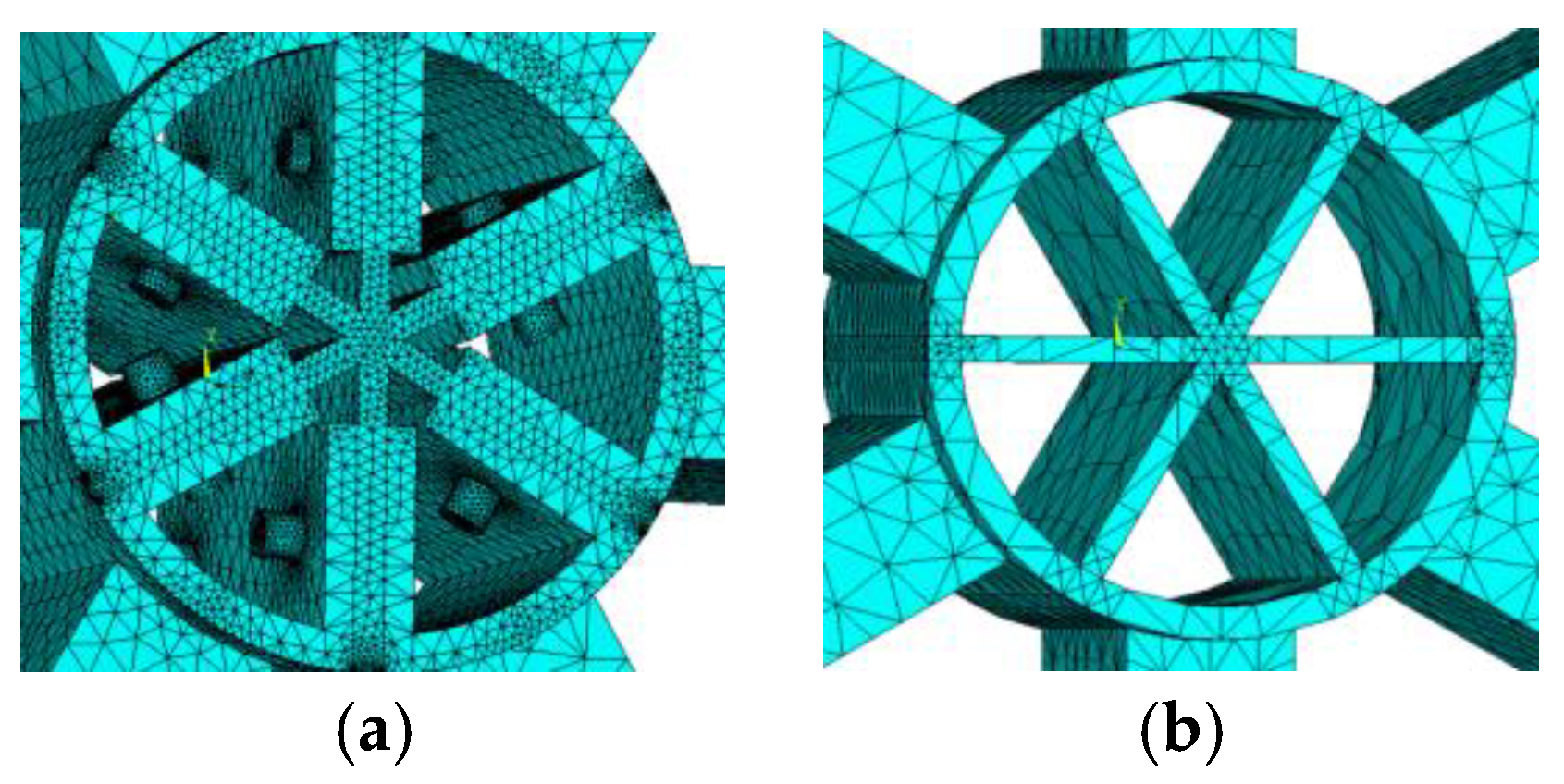
4.1. FE Models
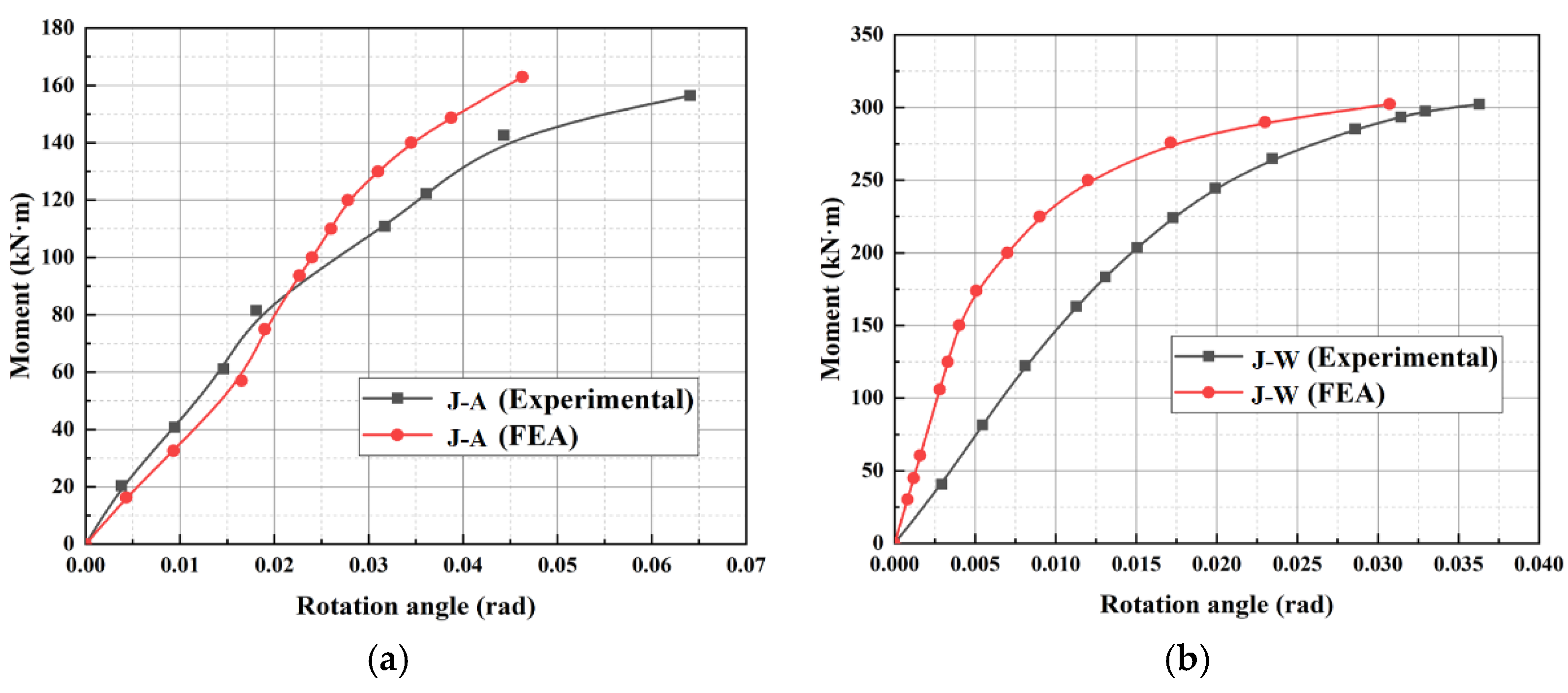
4.2. FEA Results
5. Parametric Analysis of the Rotational Stiffness of FSA Joint
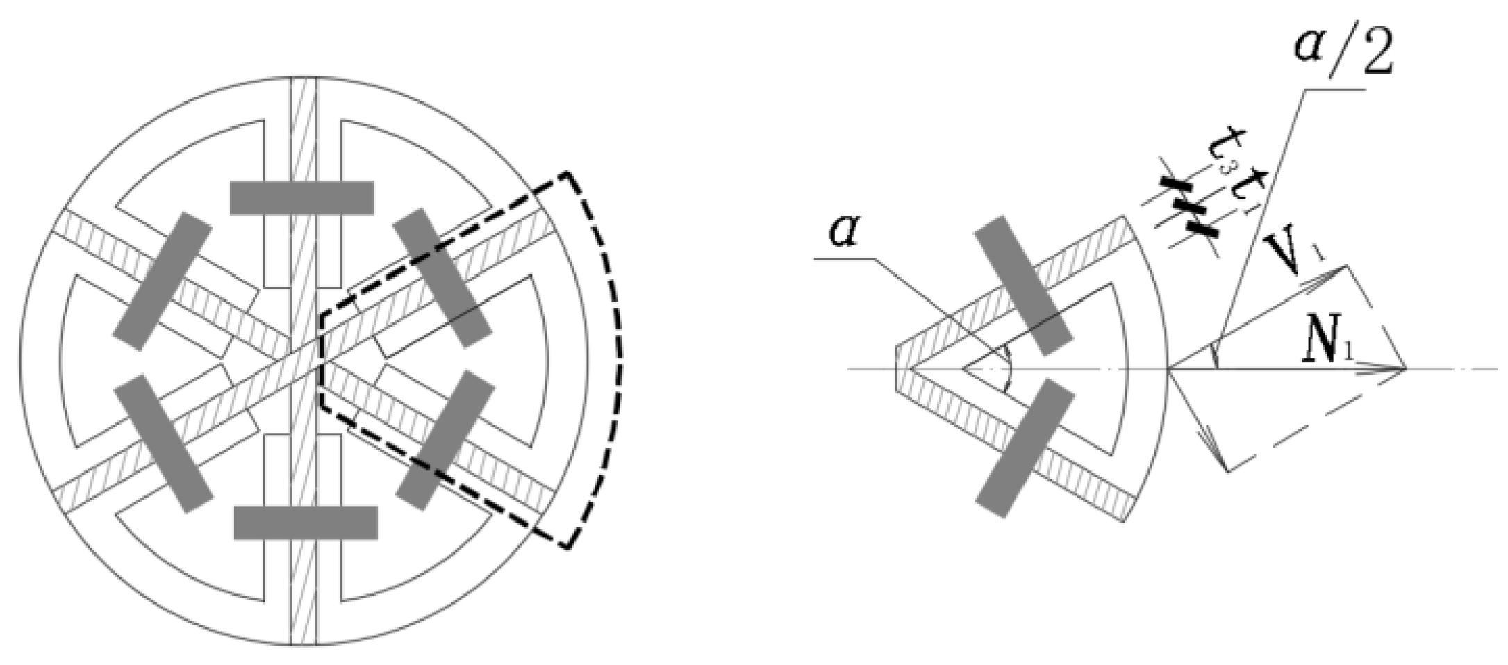
5.1. Mechanical State of Fan-Shaped Assembled Joint under Out-of-Plane Bending
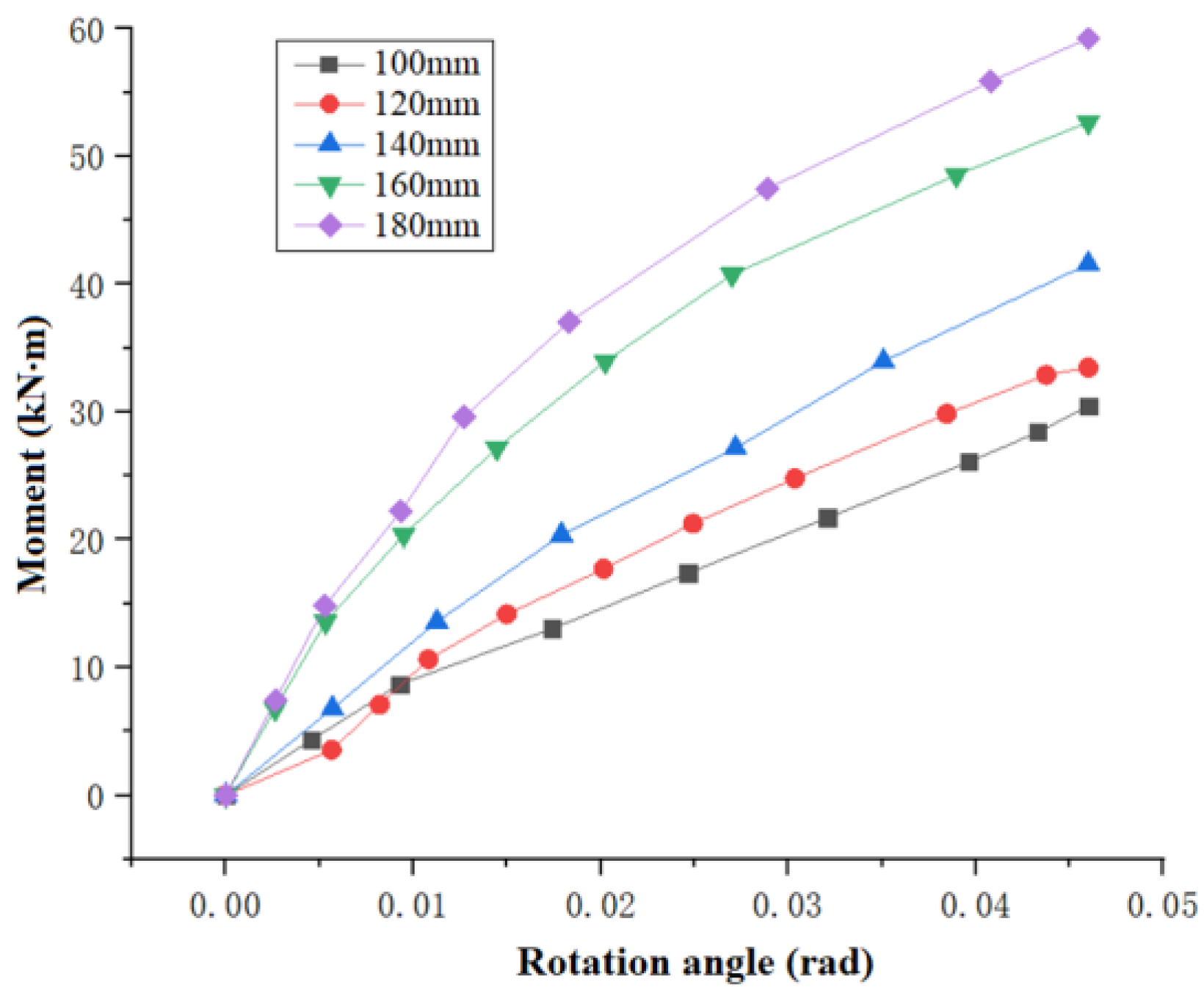
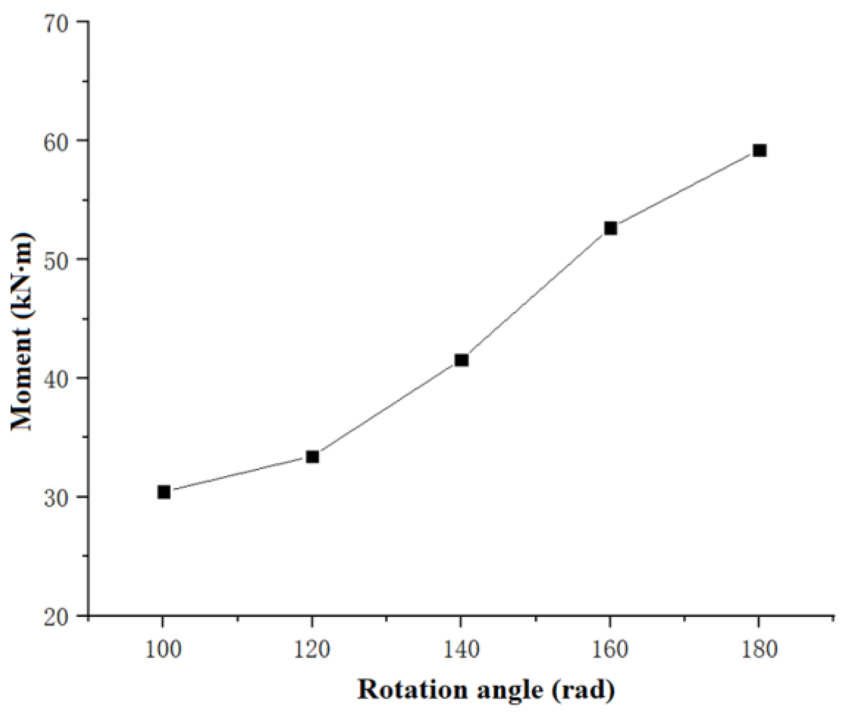
5.2. Influence of Bolt Spacing
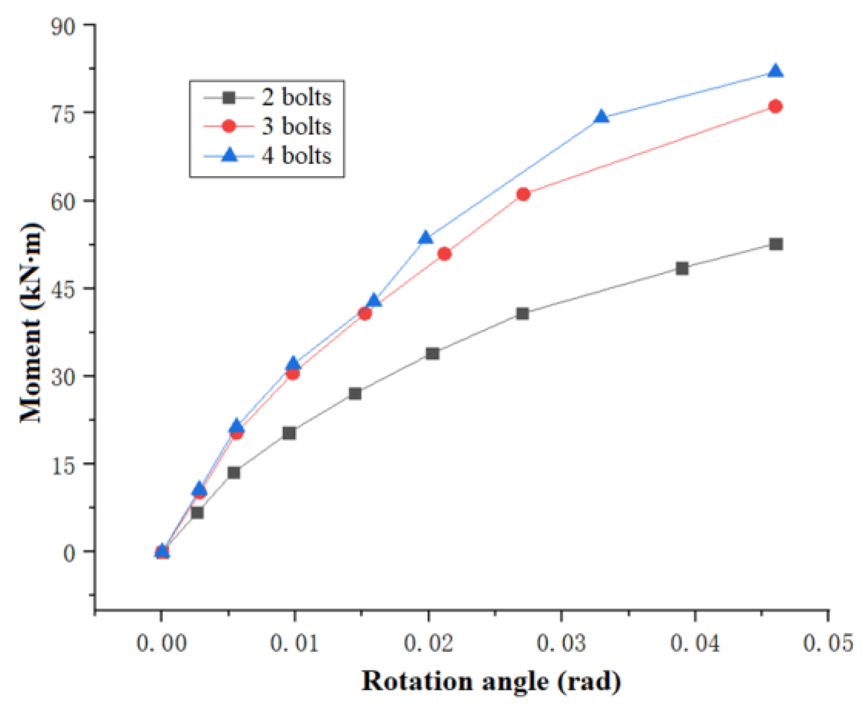
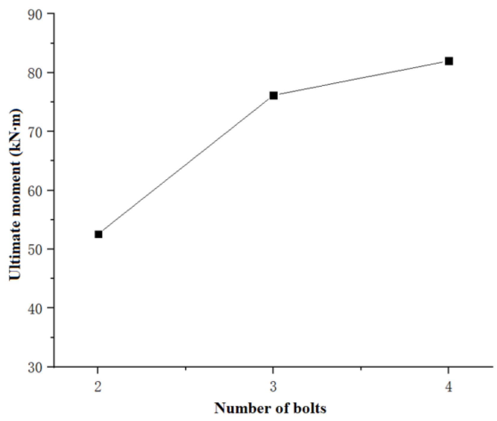
5.3. Influence of the Number of Bolts
5.4. Parameter Value Suggestions
- (1)
- To ensure the joint has a reasonable size, increasing the bolt spacing can increase the bending stiffness and capacity of the joint. The value of the bolt spacing should be based on the specific joint and should not be too small. It is suggested that the minimum h is the section height of the rectangular member.
- (2)
- With an increase in the number of bolts, the ultimate bending moment and initial stiffness of the joint are improved. Considering the joint’s details and degree of construction difficulty, three bolts are recommended for joints with a size close to that of the specimens described in this paper.
6. Theoretical Analysis of the Rotational Stiffness of the Assembled Joint
6.1. Analysis Model
- (1)
- Rotational angle θ1 caused by bolt hole wall;
- (2)
- Rotational angle θ2 caused by the deformation of the outer arc plate of the fan-shaped component.
6.2. Derivation of Stiffness k1
6.3. Derivation of Stiffness k2
6.4. Joint Initial Rotational Stiffness and Test Verification
7. Conclusions
- (1)
- The fan-shaped assembled joint shows semi-rigid characteristics, and the specimen experiences three stages: (1) the elastic stage (0–81.5 kN·m), in which the joint shows good bending performance; (2) the elastic–plastic stage (81.5–142.6 kN·m), where the bending stiffness decreases markedly to about half of the initial stiffness, and the rotation increases gradually owing to bolt slippage and deformation of the bolt hole wall; and (3) the plastic failure stage (143–156.5 kN·m), in which the bolt is brittle and the specimen fails, indicating that the key to improving the bending stiffness of the fan-shaped assembled joint is improving the shear strength of the bolt.
- (2)
- The initial rotational stiffness of the FSA joint is about one third of that of the welded joint.
- (3)
- Our parametric analysis shows that the bending stiffness and ultimate moment of the assembled joint increase when the spacing of the bolts and the number of bolts are increased.
- (4)
- The theoretical calculation formula proposed in this paper can approximately simulate the joint initial rotational stiffness of the fan-shaped assembled joint.
Author Contributions
Funding
Data Availability Statement
Conflicts of Interest
References
- Ma, H.H.; Ma, Y.Y.; Fan, F.; Zhang, Y.N. Seismic performance of single-layer spherical reticulated shells considering joint stiffness and bearing capacity. Adv. Steel Constr. 2022, 18, 604–616. [Google Scholar]
- Xu, J.S.; Fang, C.; Wang, W.; Chen, G.M. Structural design of irregular curved lattice shells in China. Proc. Inst. Civ. Eng.-Civ. Eng. 2019, 172, 37–47. [Google Scholar] [CrossRef]
- Zhao, Z.W.; Zhu, H.; Chen, Z.H. Mechanical behavior of single-layer reticulated shell connected by welded hollow spherical joints with considering welding residual stress. Weld. World 2016, 60, 61–69. [Google Scholar] [CrossRef]
- Xing, J.H.; Chen, A.G.; Yang, Q.S. In-plane bending hysteretic behavior of cruciform diaphragm welded joints with axial force. J. Constr. Steel Res. 2017, 132, 164–178. [Google Scholar] [CrossRef]
- Wang, X.Y.; Li, H.W.; Song, X.Y. Experimental investigation of failure mechanism of grid structure with bolted spherical joints. J. Constr. Steel Res. 2022, 188, 107033. [Google Scholar] [CrossRef]
- Wu, Q.Y.; Wang, H.J.; Qian, H.L.; Han, K.; Fan, F. Effect of insufficient screwing depth of bolt on mechanical behavior of bolt-ball joint and stability of single-layer reticulated shell. Eng. Struct. 2020, 213, 110590. [Google Scholar] [CrossRef]
- Tian, J.P.; Wang, X.Y.; Li, H.W.; Wang, Z.; Pan, J.R. Ultra-low cycle fatigue performance of grid structure with bolted spherical joints. J. Constr. Steel Res. 2023, 201, 107728. [Google Scholar] [CrossRef]
- Yang, D.B.; Li, M.J.; Fu, F.; Wu, J.Z. Experimental and numerical studies on a new type of bolt-ball joint for spatial grid structures. J. Constr. Steel Res. 2022, 188, 107035. [Google Scholar] [CrossRef]
- Du, B.; Yan, Y.J.; Yan, B. Finite element analysis of the hollow spherical shells plus bolts joints used for grid structures under uniaxial compression. IOP Conf. Ser. Earth Environ. Sci. 2020, 567, 012009. [Google Scholar] [CrossRef]
- Gidófalvy, K.; Katula, L.; Ma, H.H. Free-form grid shell structures on rectangular plan with semi-rigid socket joints. J. Int. Assoc. Shell Spat. Struct. 2016, 57, 295–306. [Google Scholar] [CrossRef]
- Ma, H.H.; Ma, Y.Y.; Yu, Z.W.; Fan, F. Experimental and numerical research on gear-bolt joint for free-form grid spatial structures. Eng. Struct. 2017, 148, 522–540. [Google Scholar] [CrossRef]
- Ma, Y.Y.; Ma, H.H.; Yu, Z.W.; Fan, F. Experimental and numerical study on the cyclic performance of the gear-bolt semi-rigid joint under uniaxial bending for free-form lattice shells. J. Constr. Steel Res. 2018, 149, 257–268. [Google Scholar] [CrossRef]
- Ma, H.H.; Wang, W.; Zhang, Z.H.; Fan, F. Research on the static and hysteretic behavior of a new semi-rigid joint (BCP joint) for single-layer reticulated structures. J. Int. Assoc. Shell Spat. Struct. 2017, 58, 159–172. [Google Scholar] [CrossRef]
- Guo, X.N.; Huang, Z.W.; Xiong, Z.; Yang, S.F.; Peng, L. Experimental studies on behaviour of bolted ball-cylinder joints under axial force. Steel Compos. Struct. 2016, 21, 137–156. [Google Scholar] [CrossRef]
- Jin, Y.D.; Wang, R.H.; Zhao, Y. Experiment of six-member basic structure with a pre-embedded-bolt joint for single-layer latticed shells. J. Zhejiang Univ. (Eng. Sci.) 2020, 54, 2100–2108. (In Chinese) [Google Scholar]
- Mahyar, M.; Suleyman, N.O.; Merve, S.; Burak, K.C. Analyzing of bolted joints for connecting rectangular hollow sections in reticulated shells. Archit. Eng. Des. Manag. 2023, 19, 550–566. [Google Scholar]
- Zhang, A.L.; Li, C.; Zhang, Y.X.; Liu, X.C. Static test and theoretical study on semirigid pin joint for modular steel reticulated shell. Struct. Des. Tall Spec. Build. 2022, 31, e1932. [Google Scholar] [CrossRef]
- Zhang, A.L.; Li, C.; Zhang, Y.X.; Liu, X.C. Experimental and theoretical analyses on semi-rigid pin joints under in-plane direction bending in modular reticulated shell. J. Constr. Steel Res. 2022, 190, 101128. [Google Scholar] [CrossRef]
- Mashrah, W.A.H.; Chen, Z.H.; Liu, H.B.; Amer, M.A. Static performance of novel steel dovetail joints for single-layer grid shells under out-of-plane bending moments. J. Constr. Steel Res. 2021, 187, 106988. [Google Scholar] [CrossRef]
- Mashrah, W.A.H.; Chen, Z.H.; Liu, H.B.; Amer, M.A. Mechanical behaviour of a novel steel dovetail joint subjected to axial compression loading. Eng. Struct. 2021, 245, 112852. [Google Scholar] [CrossRef]
- Mashrah, W.A.H.; Chen, Z.H.; Liu, H.B. Numerical and Theoretical Study on Mechanical Behaviors of New Dovetail Joint System (NDJs) Subjected to Tensile, Compressive, and Out-of-plane Bending Moment Forces. Int. J. Steel Struct. 2021, 21, 1108–1133. [Google Scholar] [CrossRef]
- Mashrah, W.; Chen, Z.H.; Boufendassa, R.; Liu, H.B. Numerical Parametric Study on Hysteresis Performance of the Novel Dovetail Joint for Single-layer Grid Shells Subjected to Out-of-Plane Bending Moment. KSCE J. Civ. Eng. 2023, 27, 3952–3970. [Google Scholar] [CrossRef]
- Xu, Y.; Zhang, X.N.; Han, Q.H. Research on the progressive collapse resistance of single-layer cylindrical latticed shells with AH joints. Thin-Walled Struct. 2021, 158, 107178. [Google Scholar] [CrossRef]
- Han, Q.H.; Wang, C.X.; Xu, Y.; Zhang, X.N.; Liu, Y.M. Mechanical performance of AH joints and influence on the stability behaviour of single-layer cylindrical shells. Thin-Walled Struct. 2020, 146, 106459. [Google Scholar] [CrossRef]
- Han, Q.H.; Liu, Y.M.; Xu, Y.; Li, Z.Y. Mechanical behaviours of assembled hub joints subjected to axial loads. J. Construct. Steel Res. 2019, 153, 667–685. [Google Scholar] [CrossRef]
- Yang, D.B.; Fan, K.; Zhou, G.G.; Wang, H.; Yang, H.; Zhang, M.; Zhu, B.C. Study on the mechanical performances of single-layer latticed domes with SLO joints based on beam elements FE model. J. Build. Eng. 2023, 76, 107284. [Google Scholar] [CrossRef]
- Zhang, A.L.; Liu, T.Y.; Zhang, Y.X.; Liu, X.C.; Jiang, Z.Q. Experimental and numerical research on mechanical behavior of prestressed high-strength bolt joint. J. Constr. Steel Res. 2021, 182, 106690. [Google Scholar] [CrossRef]
- Ma, H.H.; Issa, A.M.; Fan, F.; Zhang, Z.H.; Adeoti, G.O. Numerical study and design method of a single-layer spherical reticulated dome with hollow ball-tube bolted joints. J. Int. Assoc. Shell Spat. Struct. 2017, 58, 137–144. [Google Scholar] [CrossRef]
- Feng, R.Q.; Liu, F.C.; Yan, G.R.; Chang, X.L. Mechanical behavior of Ring-sleeve joints of single-layer reticulated shells. J. Constr. Steel Res. 2017, 128, 601–610. [Google Scholar] [CrossRef]
- Feng, R.Q.; Liu, S.; Dai, C.L. Performance of freeform single-layer assembled reticulated shells with double-ring joints. Eng. Struct. 2021, 232, 111802. [Google Scholar] [CrossRef]
- Zhang, Z.J.; Feng, R.Q.; Cai, Q.; Yan, G.R. Experimental and simulation study on the hysteretic behavior of double-ring joints for a single-layer grid shell under cyclic eccentric loading. J. Constr. Steel Res. 2022, 195, 107346. [Google Scholar]
- Zheng, L.; Qu, X.R.; Guo, H.; Geng, S.B. Experimental Study on a New Connection Method of Latticed Shell Joint. KSCE J. Civ. Eng. 2021, 25, 3409–3423. [Google Scholar] [CrossRef]
- Zheng, L.; Qin, C.; Guo, H.; Zhang, D.P.; Zhou, M.T.; Geng, S.B. Experimental and finite element study on the single-layer reticulated composite joints. Adv. Struct. Eng. 2020, 23, 2174–2187. [Google Scholar] [CrossRef]
- Liu, J.Y.; Lee, Y.C.; Cardoso Llach, D. Computational design and fabrication of highly customizable architectural space frames: Making a flat-cut Weaire-Phelan structure. Int. J. Archit. Comput. 2021, 19, 37–49. [Google Scholar] [CrossRef]
- Rossot, D.; Machado, R.D.; Barbieri, N.; de Lima, K.F. Experimental and numerical study of a geodesic dome under static and dynamic loads and the influence of nodal connections. Exp. Tech. 2022, 46, 823–834. [Google Scholar] [CrossRef]
- Mashrah, W.A.H.; Chen, Z.H.; Liu, H.B.; Rima, B.; Mogalli, A. Static performance of steel temcor joint subjected to out-of-plane bending moments. Structures 2022, 39, 882–900. [Google Scholar] [CrossRef]
- Mashrah, W.A.H.; Chen, Z.H.; Liu, H.B.; Rima, B.; Mogalli, A. Static performance of steel temcor joints subjected to axial tension and compression loads. Structures 2023, 47, 1113–1133. [Google Scholar] [CrossRef]
- Wu, J.Z.; Li, Y.H.; Sun, G.J.; Chen, S. Experimental and numerical analyses of the hysteretic performance of an arched aluminium alloy gusset joint. Thin-Walled Struct. 2022, 171, 108765. [Google Scholar] [CrossRef]
- Ge, H.B.; Wan, H.P.; Shen, Y.B.; Yang, C.; Luo, Y.Z. Rotational performance of semi-rigid plate-type joints for reticulated shell structures composed of plate members. Eng. Struct. 2023, 283, 115815. [Google Scholar] [CrossRef]
- Miao, F.; Dong, S.L.; Liang, H.Q.; Wang, X.T.; Zhu, X.L.; Ding, C. Manufacture and prefabrication practice on a test model of a novel six-bar tetrahedral cylindrical lattice shell. Adv. Struct. Eng. 2019, 22, 287–296. [Google Scholar] [CrossRef]
- Tan, Y.L.K.; Zhang, Y.; Zhang, Q.W.; Fan, F. Structural performance of a novel combined nested bolted joint for aluminum alloy mega-latticed structures. Structures 2023, 57, 105246. [Google Scholar] [CrossRef]
- GB/T 228.1-2010; Metallic Materials-Tensile Testing-Part 1: Method of Test at Room Temperature. General Administration of Quality Supervision, Inspection and Quarantine of the People’s Republic of China: Beijing, China, 2010. (In Chinese)
- Xu, J.S.; Chen, Y.Y.; Han, L.; Deng, C.G. Slip process analysis of regular bolt and bearing type high-tensile bolt shear connections. J. Tongji Univ. 2003, 31, 510–514. [Google Scholar]


| No. | t (mm) | (MPa) | (MPa) | (%) |
|---|---|---|---|---|
| 1 | 8 | 269.52 | 404.29 | 31.23 |
| 2 | 16 | 274.90 | 433.08 | 31.67 |
| 3 | 20 | 270.31 | 411.62 | 30.00 |
| Parameters | Values |
|---|---|
| Bolt spacing/mm | 100, 120, 140, 160, 180 |
| Number of bolts | 2, 3, 4 |
| Method | Joint Initial Rotational Stiffness/kN·m/rad |
|---|---|
| Calculated by Equation (22) | 3.12 × 10³ |
| Test | 3.36 × 10³ |
Disclaimer/Publisher’s Note: The statements, opinions and data contained in all publications are solely those of the individual author(s) and contributor(s) and not of MDPI and/or the editor(s). MDPI and/or the editor(s) disclaim responsibility for any injury to people or property resulting from any ideas, methods, instructions or products referred to in the content. |
© 2024 by the authors. Licensee MDPI, Basel, Switzerland. This article is an open access article distributed under the terms and conditions of the Creative Commons Attribution (CC BY) license (https://creativecommons.org/licenses/by/4.0/).
Share and Cite
Xu, J.; Zhu, Y.; Wu, J.; Lu, J.; Zhang, Q.; Wang, W. Rotational Stiffness Investigation and Parametric Analysis of a Novel Assembled Joint in Lattice Shells. Buildings 2024, 14, 261. https://doi.org/10.3390/buildings14010261
Xu J, Zhu Y, Wu J, Lu J, Zhang Q, Wang W. Rotational Stiffness Investigation and Parametric Analysis of a Novel Assembled Joint in Lattice Shells. Buildings. 2024; 14(1):261. https://doi.org/10.3390/buildings14010261
Chicago/Turabian StyleXu, Jianshe, Yazhi Zhu, Jin Wu, Jin Lu, Qian Zhang, and Wei Wang. 2024. "Rotational Stiffness Investigation and Parametric Analysis of a Novel Assembled Joint in Lattice Shells" Buildings 14, no. 1: 261. https://doi.org/10.3390/buildings14010261
APA StyleXu, J., Zhu, Y., Wu, J., Lu, J., Zhang, Q., & Wang, W. (2024). Rotational Stiffness Investigation and Parametric Analysis of a Novel Assembled Joint in Lattice Shells. Buildings, 14(1), 261. https://doi.org/10.3390/buildings14010261