Article

Empirical Equations for Modelling Yarn–Mortar Debonding in TRM-Strengthened Masonry Walls Subjected to Out-of-Plane Loading

by
Leonidas Alexandros S. Kouris
1,2,
Savvas P. Triantafyllou
3,
Dionysios A. Bournas
2,* and
Florentia A. Kariou
4
1
Laboratory of Engineering Mechanics, Department of Civil Engineering, Aristotle University of Thessaloniki, GR-54124 Thessaloniki, Greece
2
European Commission, Joint Research Centre (JRC), I-21027 Ispra, Italy
3
Institute for Structural Analysis and Aseismic Research, School of Civil Engineering, National Technical University of Athens, Zografou Campus, GR-15780 Athens, Greece
4
AECOM, AECOM Royal Court, Basil Close, Chesterfield S41 7SL, UK
*
Author to whom correspondence should be addressed.
Buildings 2024, 14(1), 32; https://doi.org/10.3390/buildings14010032
Submission received: 25 October 2023 / Revised: 30 November 2023 / Accepted: 13 December 2023 / Published: 21 December 2023
(This article belongs to the Section Building Materials, and Repair & Renovation)

Abstract

:
The effectiveness of textile-reinforced mortar (TRM) strengthening of masonry walls largely depends on the bond between the constituent materials. Finite element analysis (FEA) can provide valuable insights on the effect of the parameters affecting the bond; however, detailed FEA is computationally intensive. To alleviate this, we develop novel empirical equations to estimate effective textile fibre properties, thus implicitly accounting for yarn and mortar debonding. As a result, 3D finite element simulations of strengthened wall specimens are simplified and accelerated. The proposed scheme is calibrated using load–displacement paths derived from experimental data, and the simulated failure modes are compared against the experimental ones demonstrating perfect agreement. A parametric analysis is conducted, exploring the impact of the mechanical ratio of TRM reinforcement and the axial wall load on the effectiveness of TRM strengthening. We demonstrate that low values of mechanical reinforcement, corresponding to natural fibres, give rise to an 8-fold increase in the capacity of unreinforced walls. The findings draw conclusions about the efficacy of TRM strengthening in masonry structures, and provide valuable insights for optimising TRM reinforcement, considering different fibre materials and axial loads in masonry structures.

1. Introduction

Out-of-plane failure is one of the primary causes of collapse in unreinforced masonry (URM) buildings [1]. To prevent collapse of masonry structures, several conventional strengthening solutions [2] (e.g., anchors, ties, steel diagonals and plates [3,4,5,6,7]) and newer ones (e.g., binding with composite layers [8,9]) have been proposed. Among the latter, the use of composite textiles applied in an inorganic matrix, the so-called textile reinforced mortar (TRM), also referred to as the Fabric-Reinforced Cementitious Matrix (FRCM) [10], has a prominent position. In particular, the use of the inorganic matrix instead of an epoxy basis has several advantages when applied to masonry, and has therefore attracted a great interest in the strengthening of existing structures [11]. Briefly, the main advantages are its effectiveness and compatibility with masonry [12,13], excellent mechanical behaviour at high temperatures [14], and increased fire resistance [15,16]. Moreover, it can be also combined with thermal insulation for an integrated seismic and energy retrofitting of a building’s envelope [15,17,18]. It should be noted that the use of natural fibres has been investigated as a cost-effective, compatible, and lower carbon footprint solution (see, e.g., Refs. [19,20]).
The out-of-plane performance of TRM-strengthened masonry members has been investigated in several studies (see, e.g., Refs. [19,20,21,22,23,24]). Mechanical models for the design of the TRM as a strengthening material in masonry structures have been proposed (e.g., Refs. [25,26,27,28]): (i) based only on the fracture of TRM for the out-of-plane bending [20], or (ii) taking into account also masonry crushing (e.g., Refs. [25,27,29]). An assessment of the structural performance is undertaken, usually along with a damage assessment applying non-destructive techniques such as ambient vibration testing [29,30,31,32,33].
Numerical simulation for damage analysis of URM has been extensively investigated over the past years. Several methodologies have been proposed, ranging from rapid macro-models [34,35,36,37] to highly accurate, yet computationally taxing, micro-models. To reduce the computational costs associated with the distinct modelling of each constituent separately (e.g., brick and mortar), smeared cracking or continuum damage plasticity models for the homogenised material [38,39,40,41] have been proposed. Within this setting, the homogenisation theory has been a key approach to simplify the modelling difficulties related to the exact description of masonry constituents and their interactions in terms of material properties, as well as their geometry, yielding to a material which does not make a distinction between masonry units and mortar joints [42,43,44].
However, the proposed finite element (FE) models for masonry strengthened with TRM are limited. The reason is that four different materials are involved, i.e., brick units, mortar, textiles, and a matrix, with complicated interactions, which leads to numerous and complex damage modes that, in principle, span different length scales. Within this physics-rich and computationally demanding setting, standard FE procedures typically used for URM become prohibitive. Hence, simplified assumptions are required to strike a balance between computational efficiency and accuracy, while reducing the need for exhaustive material characterization.
An FE model for TRM was developed to investigate the effect of a non-planar laying of the textile inside the matrix on the tensile behaviour of a single TRM layer [45]. Two-dimensional simulations for TRM-strengthened masonry walls typically involve plane stress/strain FEs for the masonry and the TRM matrix. The textile is modelled as either a grid of linear elements [46], plane stress elements [47,48,49], or as an embedded reinforcement [50]. Masonry can be represented either by a homogenised continuum [47,49,50], or employing different elements for the bricks and mortar [46,48]. A perfect bond between the masonry, the inorganic basis, and the textile has been so far assumed.
Simulation strategies in 3D have also been examined, which involve non-associated plasticity laws for brittle materials calibrated with experimental data with a perfect bond between the various elements [51,52]. A similar procedure has also been proposed for engineered cementitious composite (ECC), where an external jacket is applied comprising steel fibres sprayed in a cementitious mortar (e.g., Ref. [53]); the jacket and the masonry are connected through an interface simulated using elastoplastic elements [54], or a cohesive interaction model [55,56]. In all these approaches, certain material properties of the composite are calibrated with the available experimental results.
Although the bond behaviour has been the focus of several recent experimental and analytical studies (e.g., Refs. [57,58,59,60,61]), the topic still remains open; detailed finite element simulation of the mechanics at the mortar–fibre interface results in computationally intensive models. Furthermore, identifying micro-mechanical interface parameters necessitates involved experimental procedures, often resulting in significant variance. In this paper, we derive and present novel empirical equations to define the effective properties of the textile due to the interaction within the reinforcing mortar. Thus, the bond slip effects are indirectly accounted for by establishing empirical coefficients to control the effective strength and elastic modulus of the textile. This new (and, to the best of our knowledge, first) empirical relationship proposed in this study is calibrated to experimental results, and significantly facilitates the simulation of the interaction between the matrix and the textile. Using this model, a parametric analysis is carried out to investigate the influence of the mechanical reinforcement ratio, the strength of the textile and the axial load of the walls.
The rest of this article is structured as follows. In Section 2, the experimental results used for model validation are briefly discussed. In Section 3, the FE modelling procedure is presented, including the employed effective constitutive model for the fibre–textile interface. The results of the finite element analysis conducted for model calibration are presented in Section 4. In Section 5, the proposed empirical equations for interface bond are derived and a thorough study of the influence of the various parameters is provided. Finally, in Section 6, the results of the parametric analysis on the effect of the fibre reinforcement ratio and the masonry axial load using the developed empirical equations are presented.

2. Brief Description of the Experimental Methodology

In this section, the main material properties and results of a past experiment [21] used for the calibration and the validation of the model are briefly discussed. We opted for this methodology due to the large variety of investigated parameters, including the thickness of the masonry wall, three different textile materials, various number of layers, coated and untreated (uncoated) textiles, etc. Thus, the simulation of all these different parameters can result in an unbiased simulation strategy, while the same laboratory conditions ensure the compatibility between tests. Further details can be found in the relevant paper [21].

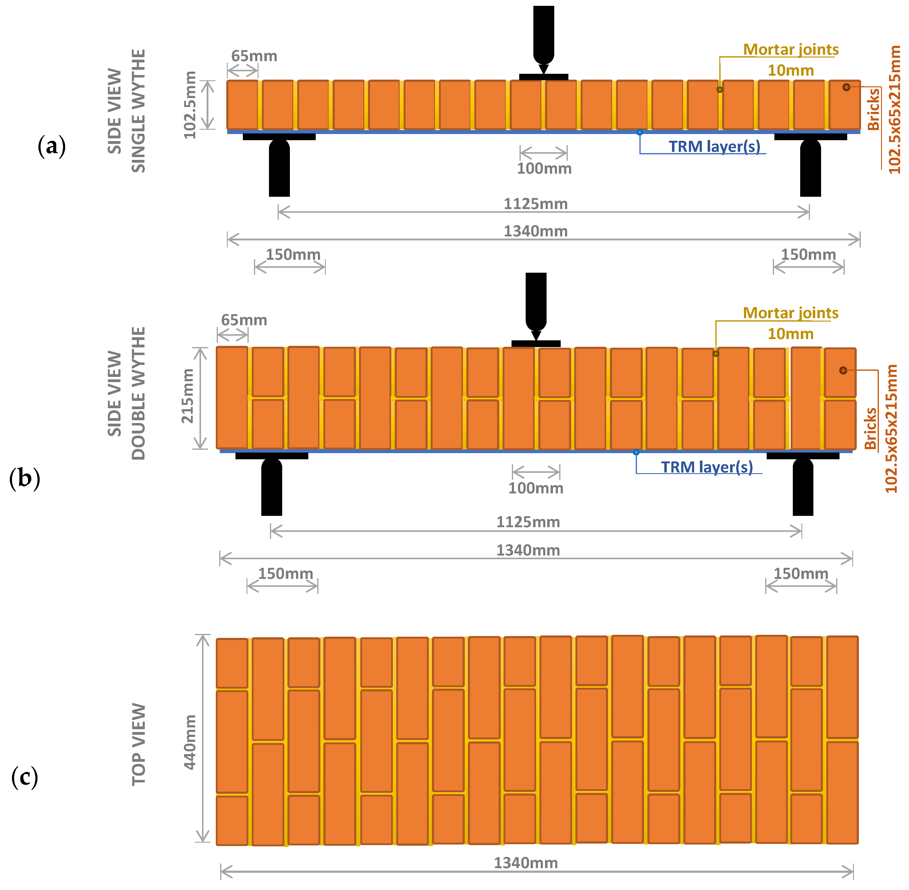
2.1. Test Design and Set-Up

The experiment involved a series of eighteen specimens tested in three-point bending, including two control (unstrengthened) specimens. The experiments were conducted in displacement control, at a rate equal to 0.017 mm/s. The loading was applied in the middle of the masonry piers, whose dimensions are presented in Figure 1. The wall thickness varies, as a single wythe (S) of 102.5 mm thick, and a double wythe (D) of 215 mm thick specimens were tested. Three different textile fibre materials were used: (i) carbon (C), (ii) glass (G), and (iii) basalt (B). There are two sets of specimens: in the first set, the layers of textile were trowelled onto to the tension surface of the masonry beams without any coating, while in the second set, the textile had been impregnated in an epoxy resin before being trowelled, and is referred to herein as Co. The coated basalt fibres were pre-impregnated by the manufacturer (and, as such, there were no uncoated basalt counterpart textiles), while the carbon and glass textiles were impregnated at the laboratory (for the details, see [21]). The number of layers, also being a parameter under investigation, were 1, 3, and 7.
Regarding the specimens designation, the first letter of the tagging is S or D, referring to single- or double-wythe masonry; the second letter refers to the textile material, with C standing for carbon, G for glass, and B for basalt; and the following number stands for the number of layers (1, 3, or 7), while the suffix Co stands for coated textiles. Specimens’ properties are summarised in Table 1 and Table 2.

2.2. Material Properties

The masonry’s vertical elastic modulus E and nominal strength fm are equal to 2.5 GPa and 9.7 MPa, respectively. These were estimated from the mean of three compression tests of masonry wallettes [62]. The compressive and tensile strength of the masonry’s casting mortar was 7.4 MPa and 1.9 MPa, respectively. The compressive and tensile strength of the matrix mortar were found to be equal to 39.7 MPa and 9 MPa, respectively. Three different composite textiles were used: (i) carbon with a nominal thickness of 0.097 mm, glass with a nominal thickness of 0.044 mm, and basalt (coated textile) with a nominal thickness of 0.037 mm. The material properties are summarized in Table 1. The properties of the textile fibres are according to the manufacturers’ datasheets.

2.3. Test Results

Two generic failure modes for walls, or even a combination of them, can appear: (i) textile failure (TX) or (ii) masonry failure (MR). Textile failure can specifically occur either as fibre breakage (FB), textile debonding (DB), or slippage (SL). Masonry failure can be either flexural with vertical cracks (FL), shear with diagonal cracks (SD), or shear sliding of the bricks on the mortar joints (SV) due to loss of bonding. Furthermore, in both failures (i.e., TX and MR), a combination of the failure modes is possible, all of which were observed experimentally and are presented in Table 2. Hence, a large variation in damage modes exists, depending on the bonding capacity, the relative strengths of masonry fm and the textile ft, and the amount of textile reinforcement. To correlate the damage mode with the latter, we employ the mechanical ratio of the textile reinforcement ωt as a key parameter controlling the damage mode:
ω t = ρ w f t f m ,
ρ w = A t e x A w a l l = t n o m t w a l l ,
where Atex is the cross section of the fibres and Awall is the cross section of the wall. Their ratio ρw is equivalent to the ratio of the nominal thickness of the fibres tnom to the thickness of the wall twall. The main test results are summarised in Table 2, including the maximum force and maximum displacement, as well as the failure mode along with the mechanical reinforcement ratio.

3. Out-of-Plane Damage Modelling of TRM Strengthened Masonry Walls in Abaqus

3.1. Masonry

3.1.1. Homogenised Model

Under the assumption of periodicity, the representative volume element’s (RVE’s) elastic properties can be determined experimentally from masonry prisms, or from the properties of the constituents and the application of a homogenisation rule, which should ideally consider the orthotropic elastic properties [44]. Since, in the experimental methodology considered herein, the masonry walls undergo normal stresses along the direction of the bed joints, the elastic modulus of the masonry perpendicular to the bed joints from Table 1 was employed.

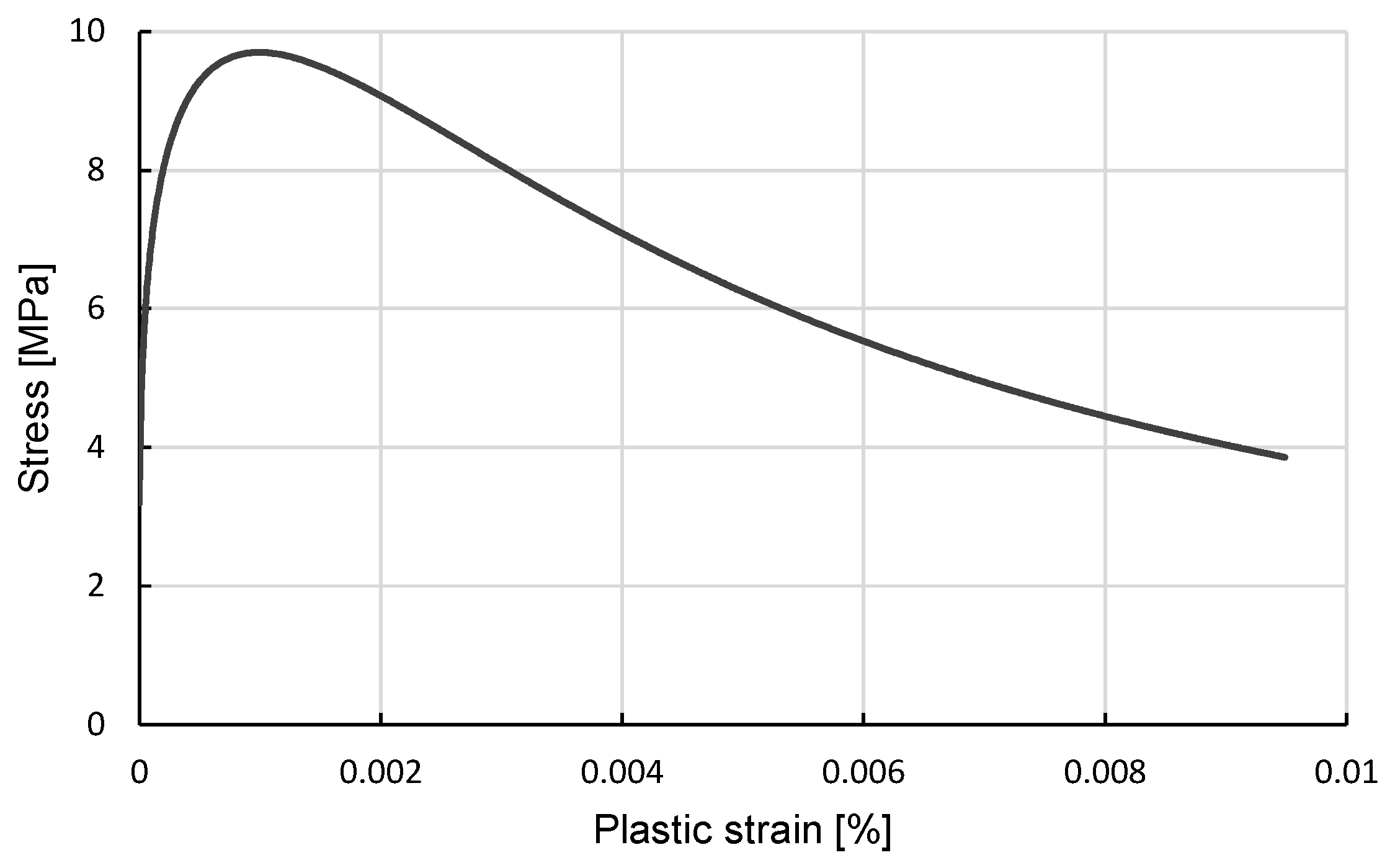
3.1.2. Plasticity Model

Each brick representing the RVE is modelled using the concrete damage plasticity (CDP) constitutive model. Although CDP has been developed specifically for concrete, it can also be used for masonry or other brittle materials, provided that the corresponding material parameters are properly calibrated (see, e.g., Refs. [51,52,63]). For the uniaxial compression behaviour, a law proposed specifically for masonry [64] is adopted. Within the context of CDP, this is introduced in pairs of axial plastic strain εp vs. compressive stress σ (Figure 2). The masonry’s compressive strength, which has been estimated experimentally, is equal to 9.7 MPa (Table 3). The adopted yield function of masonry is the one initially proposed by [65] and enhanced by [66].
The evolution of plastic strains ijp is controlled by the plastic flow rule, which relates the strain rate to the derivative of the plastic potential function Q with respect to the stress components  σ i j  through the plastic multiplier dλ (Equation (3)).
d ε i j p = d λ Q σ i j ,
The parameters of the proposed model, which were not experimentally identified, are fine-tuned by carrying out a sensitivity analysis against the experimental results of the double-wythe control specimen, and are presented in Table 3. The required key parameters of the masonry model comprise: (i) the dilation angle, ψ, in the p–q plane; (ii) the flow potential eccentricity, ϵ; (iii) the ratio of initial equibiaxial compressive yield stress to initial uniaxial compressive yield stress, σb0c0; (iv) the ratio of the second stress invariant on the tensile meridian to that on the compressive meridian, K; and (v) the viscosity parameter, μ. The single-wythe control specimen was not used for the calibration because it failed in its own weight [21].
The comparison of the simulated load displacement path against the experimental response is shown in Figure 3, where a very good agreement is observed. In particular, the elastic and softening behaviours are captured sufficiently well.

3.1.3. Brick/Mortar Interface Model

The RVE interface properties are accounted for through a cohesive surface model, which can simulate the SV failure mode of the masonry. A bi-linear traction separation law is employed, as shown in Figure 4. The elastic response is assumed uncoupled in three directions, and is defined according to Equation (4), where  t n ,   t s , and  t t  are the tractions along the normal (n) and tangential directions (s, t), respectively. Furthermore,  δ n δ s , and  δ t  are the corresponding interface displacements, and  K n n ,   K s s ,   K t t  are the corresponding elastic stiffnesses. Finally,  d  is a damage variable, which is zero until damage initiation and assumed to linearly increase to 1 thereafter.
Damage initiation occurs according to the maximum stress criterion defined in Equation (5), where  t n 0 ,   t s 0 , and  t t 0  are the interface strengths along the normal and tangential directions, respectively. It is of interest to note that damage along the normal direction only initiates under tension.
t = t n t s t t = 1 d K n n 0 0 0 K s s 0 0 0 K t t δ n δ s δ t = 1 d K · δ .
d m a x t n t n 0 , t s t s 0 , t t t t 0 = 1 .
The cohesive stiffnesses in Equation (4) should correspond to the RVE’s elastic properties, as during the elastic response, there is not relative displacement at the interface. Using the RVE, since the interfaces have zero thickness, the following homogenisation rule can be applied:
K n n = E u E m t m E u E m ,
where Eu and Em are the elastic moduli of the units and the mortar, and  t m  is the thickness of the mortar joints. The values for the cohesive normal stiffness were, hence, established as  K n n = 4   M P a / m .  Since no in-plane sliding was observed in the experiments, the values for the in-plane cohesive stiffness was assumed to be 10 times the normal one, i.e.,  K s s = K t t = 40   M P a / m . As there was no sliding between masonry units, a typical friction coefficient was selected equal to 0.7 (see, for example, Refs. [67,68,69]). A hard contact law is considered along the normal to avoid interpenetration. The interface strength along the normal was assumed to be 25% of the mortar strength, i.e.,  t n 0 = 0.5  MPa, while in the other two directions was  t s 0 = t t 0 = 75  MPa. A typical value for the fracture energy GE = 0.25 kN/m [70,71] is employed.

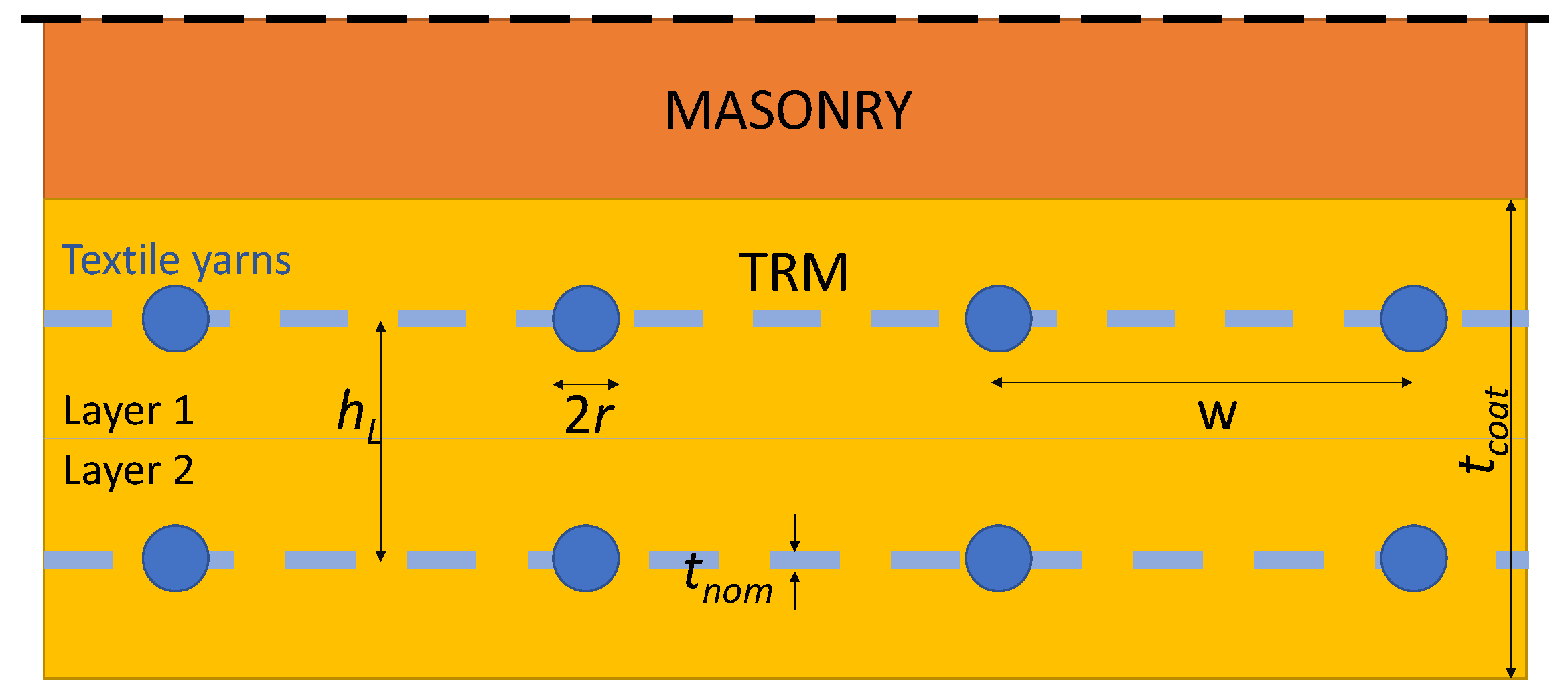
3.2. Textile Reinforced Mortar

The Drucker–Prager (DP) plasticity model is used to simulate the non-linear (NL) behaviour of the TRM matrix, which allows for different yield limits in tension and compression combined with an isotropic hardening and softening of the material under compression. The evolution of the yield surface with NL deformation is defined based on the uniaxial compression yield stress of the masonry assemblage. The linear DP yield surface F in the stress invariants t-p plane involving the friction angle β and the cohesion d is expressed with respect to the hydrostatic pressure p as
F = t p   t a n β d
t = 1 2 q 1 + 1 R 1 1 R r Q 3
where R stands for the flow stress ratio, q for the von Mises equivalent stress, r for the third invariant of deviatoric stress, and Q for the plastic potential function. Note that, in this modelling approach, the plastic potential function Q in Equation (8) is assumed identical to the DP yield function F, and the friction angle β equal to ψ (i.e., the dilation angle).
The textile in the mortar matrix is modelled via an embedded reinforcement approach [72]. In this setting, the full bond between the embedded reinforcement and the parent mortar element is assumed. In reality, however, a slip bond occurs between the yarns and matrix. In this work, this is accounted for by defining effective material properties for the textile, as discussed in the next section.
The dilation angle ψ is not constant during loading [73], and it has been shown that, for extensive and cyclic shear, loads tend to zero [74]. Therefore, the angle of dilation ψ can be intuitively related to the angle of internal friction φ. For non-cohesive soils (i.e., sand, gravel) with the angle of internal friction φ > 30°, the value of dilation angle can be estimated as ψ = φ − 30°. A negative value for the dilation angle is acceptable only for rather loose sands. The value of ψ = 0 corresponds to the volume preserving deformation while in shear. The calibrated parameters are summarised in Table 3.

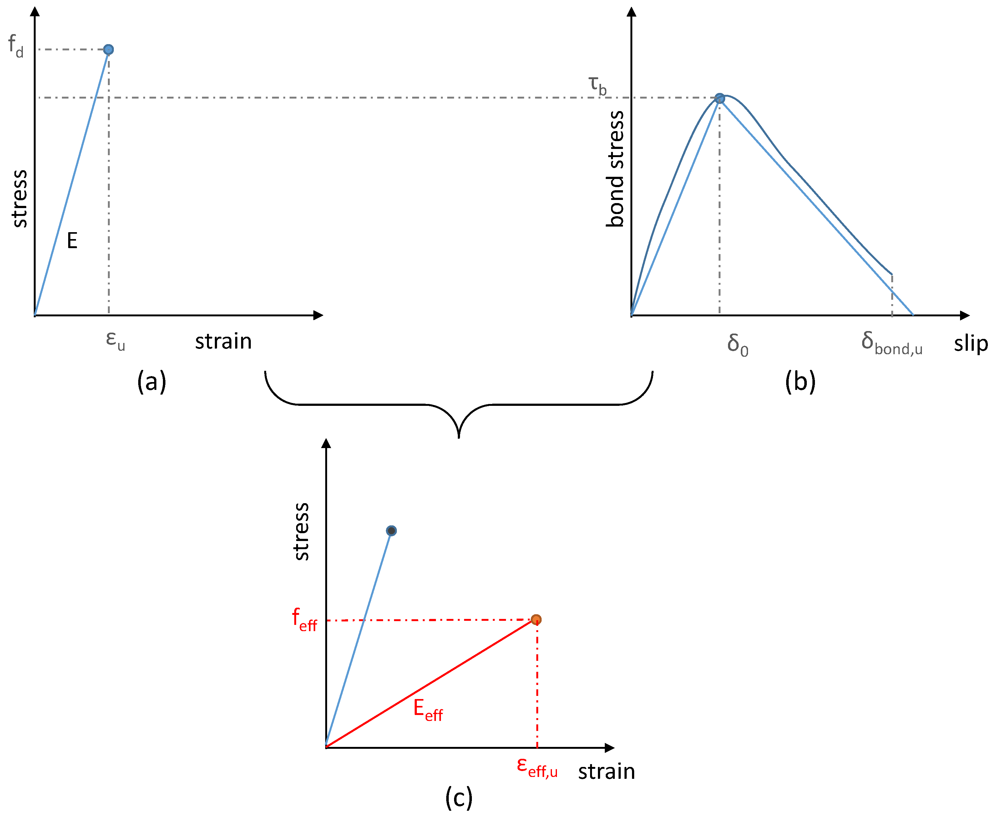
3.3. Interaction between Matrix and Fibres

The stress–strain response of a perfectly-bonded TRM strengthened masonry is generally assumed to be trilinear, as shown in Figure 5, where the three subsequent phases I, IIa, and IIb are characterized by the moduli E1, E2 (=0), and E3. This can be further reduced to a linear one (see Figure 6a). However, the complex interactions between the filaments, yarns, the matrix, and the masonry result in a macroscopic debonding and an uneven stress distribution of the fibres microscopically. A thorough description of the several steps that the debonding undergoes with increasing load can be found in [75].
Taking into account the brittle macroscopic response of the TRM, rather than modelling the actual slip and debonding NL process, macroscoping bond slip models provide an appealing alternative. Within this setting, the properties of the TRM are defined on the basis of effective fibre textile properties that implicitly account for the debonding process within the matrix (Figure 6b).
The macroscopic slip is a curve usually idealized as a bilinear one [76,77], as shown in Figure 6b. The macroscopic slip δbond is turned into a strain εbond using the fibre length L: εbond = δbond/L. The effective strain of the fibre εeff is the sum of the linear one and εbond. Therefore, the effective elastic modulus and the effective strength of the textile can be defined as follows:
ε e f f = ε + ε b o n d  
E e f f = σ ε e f f
f e f f = E e f f · ε e f f , u
In Equation (11) the ultimate strain is denoted as εeff,u, and is the minimum of the sums:
ε e f f , u = ε + ε b o n d ε u + ε b o n d , u
where the ultimate strains εu and εbond,u = δbond,u/L are defined in Figure 6a,b, respectively. Applying these empirical rules, the loss of the cohesion and the consequent slip of the textile inside the reinforcing mortar is included within an effective elastic modulus and strength of the textile representing both phenomena; this schematically is shown in Figure 6.

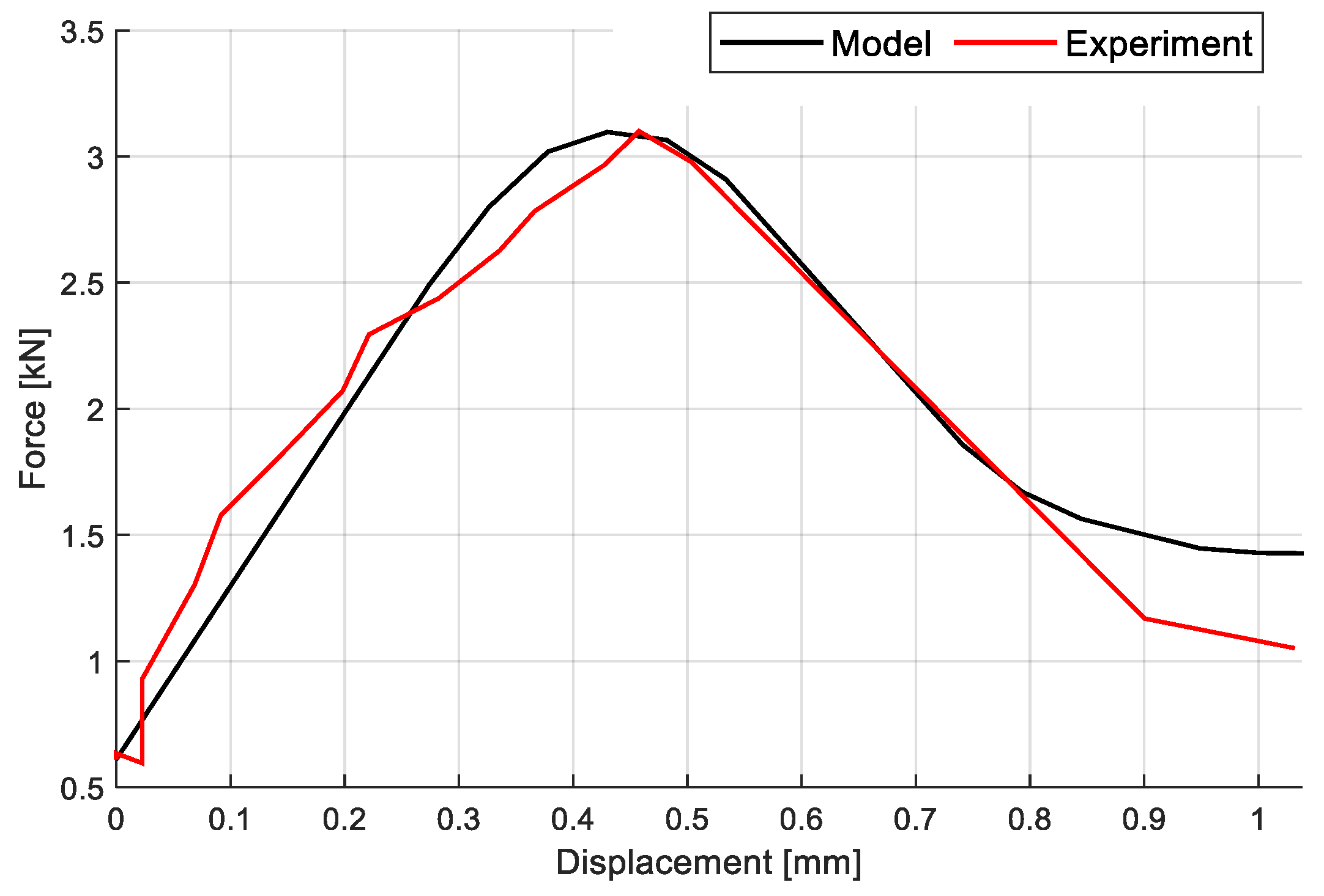
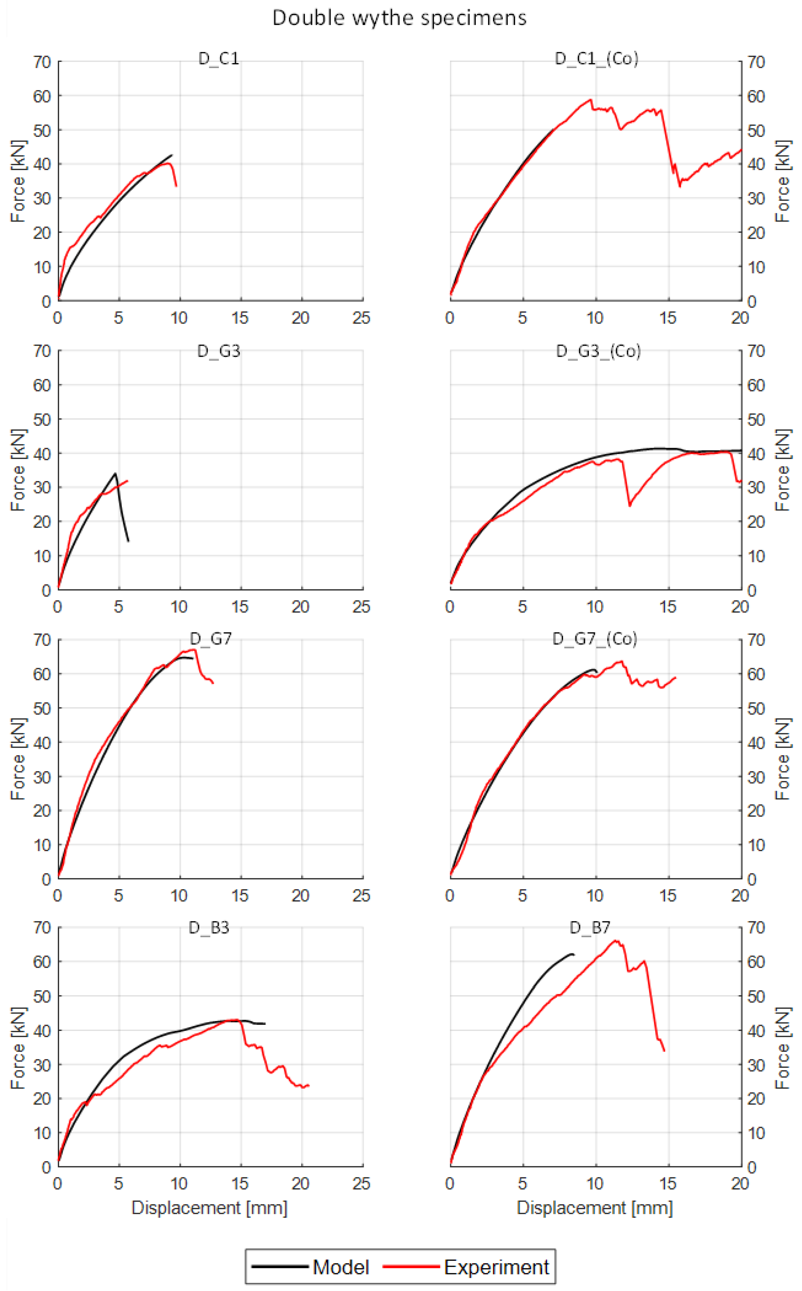
4. Calibration of TRM Model

The TRM-strengthened specimens of the experimental campaign conducted by Kariou et al. [21] were modelled using the FE model, and a calibration of the slippage and bond loss of the textile was carried out. The masonry elements were modelled with 8-node reduced-integration hex elements. The TRM was modelled using conventional 4-node shell elements.
A uniform FE mesh, with a maximum size of approximately of 50 mm, was employed with close-to-unity aspect ratios to minimize approximation errors. The specimens were supported by steel plates and rollers (see Figure 1), with “zero” resistance to uplift and a very high compression stiffness. The model does not consider the subgrade stiffness and, instead, a full restrain of the vertical DOFs along the support line is applied. Finally, a displacement-controlled load is applied directly to the nodes of the specimen relative to the surface of the steel plate.
The elastic modulus Et and the strength ft of the TRMs are calibrated using the experimental results, namely the load–displacement curves. The effective properties of the TRM reflect the simulation assumptions vis-à-vis its anticipated failure modes, i.e., (i) failure of the bond of the yarns in the matrix has not been explicitly modelled, and (ii) the failure of the bond between the textile and the matrix which, however, is not the case for common masonries and mortars.
The effective properties of the TRM introduced in the numerical model can account for the loss of bonding and the subsequent slippage of the yarns. In this regard, the notion of a reduction factor Ω is introduced as follows:
Ω E = Ε e f f E t ,  
Ω f = f e f f f t
where ΩΕ and Ωf are the reduction factors for the elastic modulus and strength, respectively, defined as the ratio of the effective to the actual values. Table 4 presents the respective values, as well as the stress of the fibres and the nominal elastic modulus and strength.
The analytically calculated and experimentally derived out-of-plane load–displacement curves are shown in Figure 7 and Figure 8, respectively, where a very good match can be observed. In all cases, a lower than 10% variation in the maximum strengths and displacements with the experimental values is achieved. In particular, the elastic stiffness and the nonlinear response of the specimens are captured well. Furthermore, the failure mode is also correctly estimated.
A reasonably good match (also given by the implicit analysis) between the specimen at the final state of the experiment and the damaged shape of the analytical model is also observed. In Figure 9, the absolute maximum principal strain at the final step of the analysis is compared with the damaged specimen. For specimen SC1, the failure mode is related to a principal crack in the middle of the TRM layer, accurately captured by the FE model. Specimen SB7 failed in a combined shear diagonal and flexural mode (see also Table 2), which the FE model also experienced. Finally, some FEs of the textile and masonry were damaged in the model of DB3, while the actual specimen underwent a combined failure of masonry and TRM.

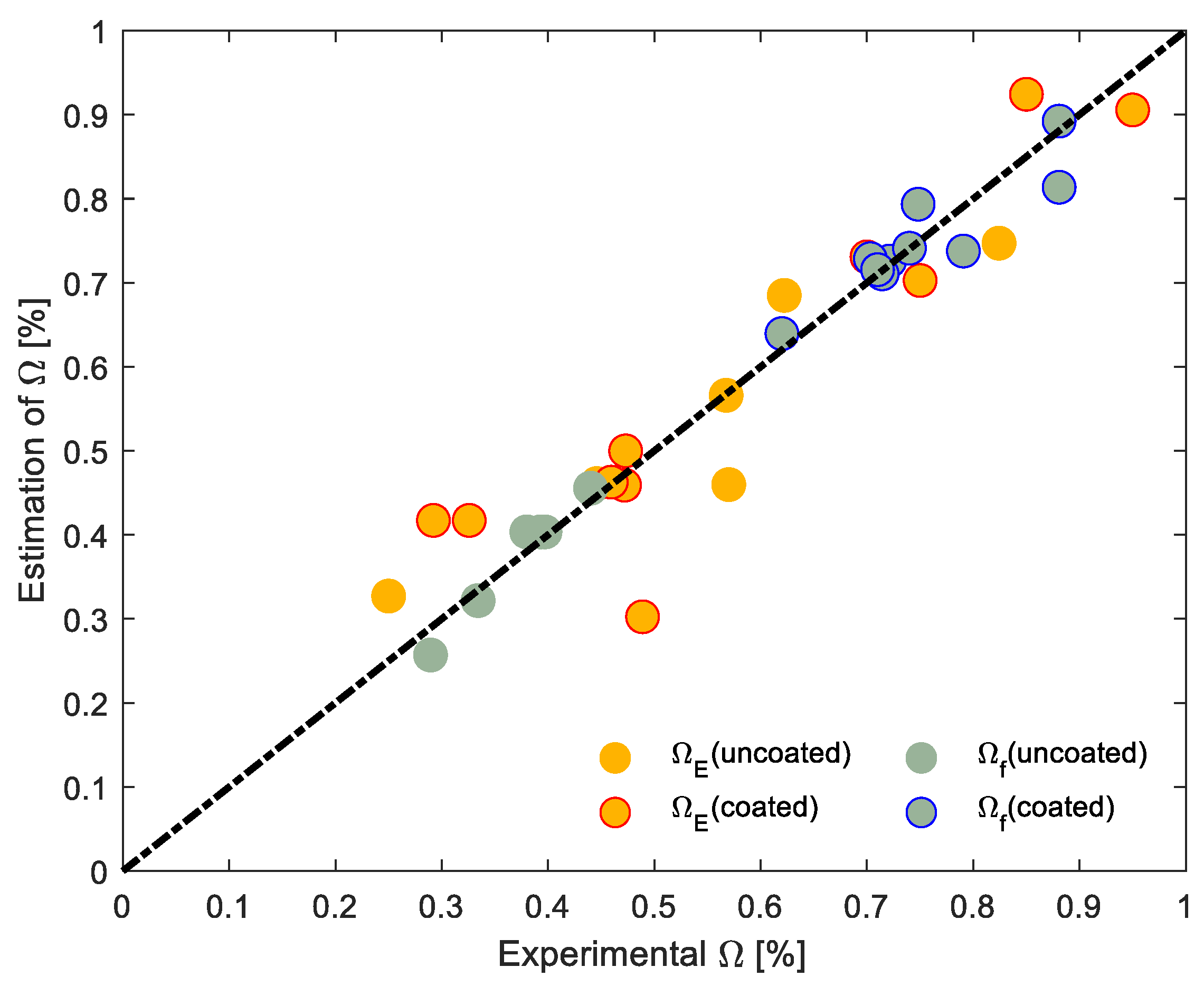
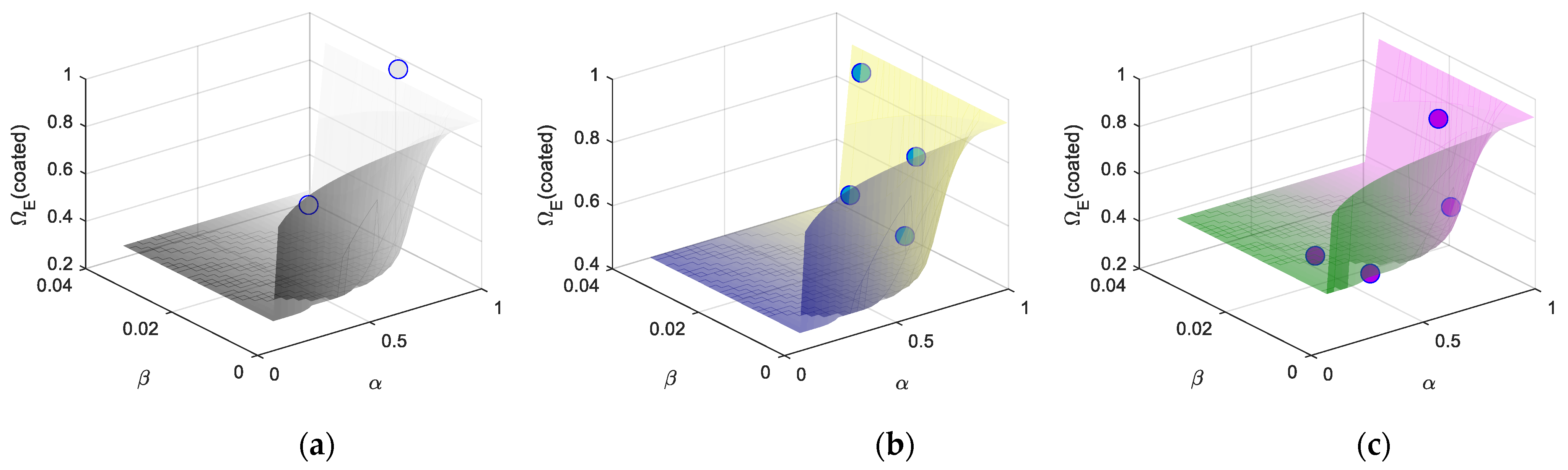
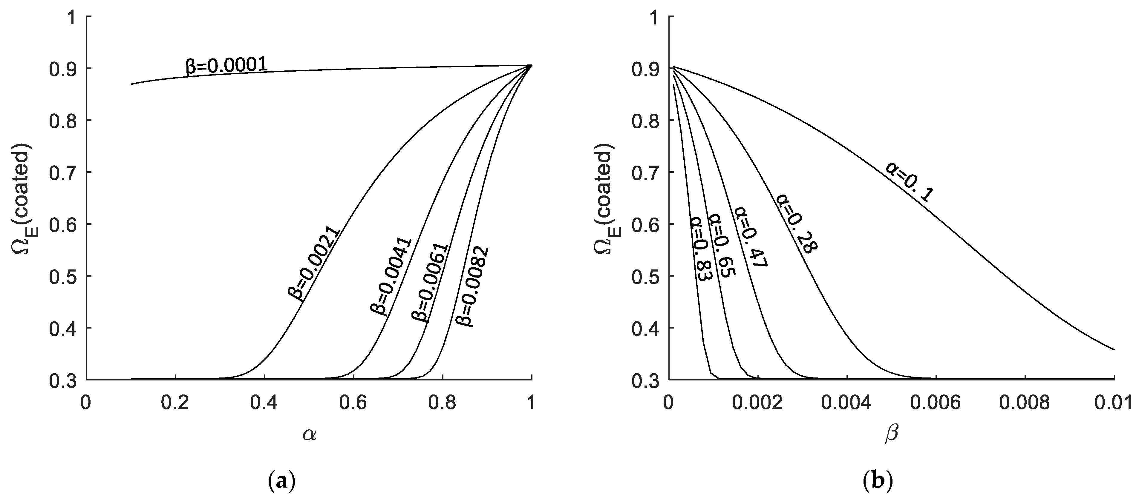
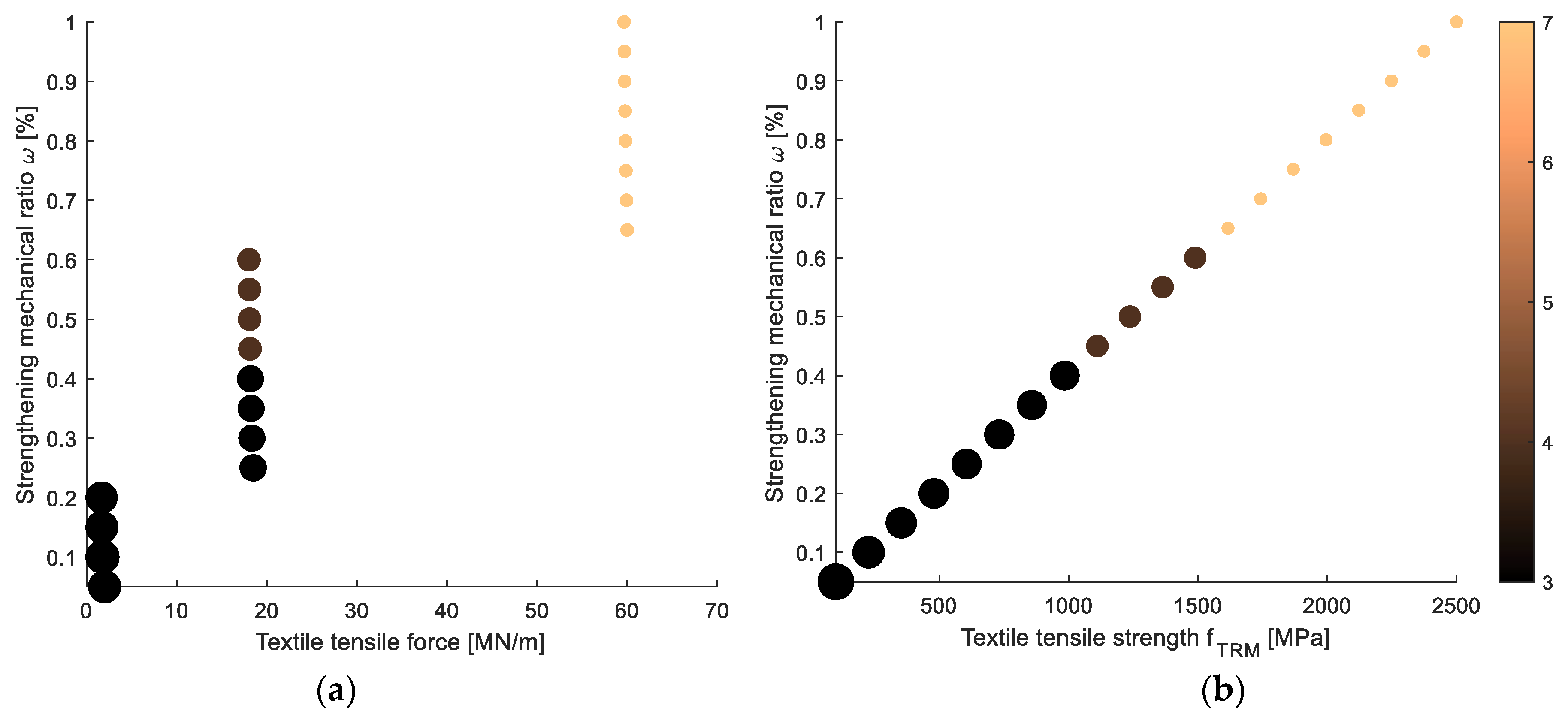
5. Empirical Equations for the Reduction Coefficients

Using the proposed model, the elastic modulus and the textile strength should be treated with their effective values, depending on the bond slip and the effective total strain (Equations (9)–(12)). The imperfect bonding allows the textile to slip in the matrix up to the total loss of cohesion. This telescopic slippage [78] is mainly influenced by the external treatment of the textiles (coating) and the impregnation of the textile yarn with the surrounding inorganic matrix [79], whereas the placement of the textile can influence the bonding [45]. The impregnation and the textile placement are uncertain parameters that cannot be explicitly accounted for in a FE model for the latter to be of practical use. It should be noted that a slippage between the substrate and masonry is not commonly observed [75]. Moreover, it has been observed that, by increasing the number of textile layers, the local slippage of fibre filaments through the mortar results in debonding at the (masonry or concrete) substrate due to the better mechanical interlock conditions created by their overlapping. Apart from the external coating of the yarns, the geometric and material parameters of the textile and the matrix that control the bonding are: (i) the diameter 2r of the yarns, (ii) the distance w between the yarns, (iii) the thickness of the jacket tcoat, (iv) the perpendicular distance between the textiles equal to hL (which for centrally positioned textiles is equal to the thickness of a layer), (v) the elastic moduli of the textile Et and the matrix Em, (vi) the tensile strength of the textile and the matrix, (vii) the number of textile layers n, (viii) the volumetric ratio of the textile in matrix, and (ix) the stress of the textile σt. The geometric parameters are explained in Figure 10.
The correlation coefficients of these parameters with the effective ratios of the elastic modulus and tensile strength of the textile are over 0.5 and reveal a causal dependence, and are included in the following three unitless coefficients:
α = σ t f t 1
β = π · r 2 w · h L = t n o m · n t c o a t 1
γ = E m E t
where n is the number of textile layers and tcoat is the total thickness of the TRM jacket (see the values in Table 2). In accordance with the bond-slip model of embedded steel reinforcement in reinforced concrete structures [80], we define the ratio of the effective textile elastic modulus Et,eff and bonding slip according to the following equations:
Ω E , f = 1 1 e p 1 α p 2 β l n γ p 3
where Ω is the reduction coefficients defined in Equations (13) and (14), and p1, p2, and p3 are model coefficients. The logarithmic term in the right hand side of Equation (18) weighs the extreme values of ΩΕ,f. The comparison of the empirical model and the calibrated experimental values is shown in Figure 11, where a good performance of the selected reduction function is noted.
The calibrated coefficients of the empirical equations for the case of coated and uncoated specimens are shown in Table 5. The goodness-of-fit metrics (i.e., the R2 and the p-values) are also provided. The empirical model is found to converge effectively with the data achieving robust determination values (R2 > 0.8 and p < 0.01).
To better visualise the empirical curve, a 3D plot of the calibrated values of ΩΕ for the coated textiles with the α, β coefficients, as defined in Equation (18), is shown in Figure 12. In the same plot, the surface of the empirical equation is shown, where a minimum value of ΩΕ (lim ΩΕ|α → 0 and β → 1) emerges for the textiles under consideration; this varies between 0.3 and 0.44.
The sensitivity of the empirical equation vs. the coefficients α and β is highlighted in the 2D plots provided in Figure 13. The empirical equation is bounded and, for the experimental carbon and matrix properties, this variation is between 0.3 and 0.9, as presented in Figure 13a. Obviously, the higher the tension a textile can sustain, the higher would ΩΕ be. Hence, increasing values of α result in increasing values of the ΩΕ coefficient. Moreover, the thinner the nominal thickness is (hence the yarn), the less is the influence of the tensile stress. This can be attributed to the degree of impregnation of the yarn; if the roving is thick then, it is made of several fibres and the degree of impregnation of the surrounding matrix in the inner fibres is low, resulting in an uneven stress state. Due to this stress distribution, in Figure 13b, it is seen that low stress receives a smoother variation in ΩΕ concerning the radius of the yarn, whereas for high stresses, the ΩΕ coefficient degrades quickly. These remarks agree with experimental investigations of bonding mechanisms [77].

6. Parametric Analysis

6.1. Parameters

TRM composites with varying strengths from as low as 100 MPa to 2500 MPa (effective strength values) are applied to the masonry piers. The key parameter is the mechanical reinforcement ratio ωt (Equations (1) and (2)), which varies largely (namely from 0 to 1), whereas in the experimental campaign varied from 0.03 to 0.43 (Table 2). The textile volumetric ratio varies also up to 0.49%, whereas in the experiment, the corresponding values ranged up to 0.3%. Each textile has its own texture with varying filaments, roving, yarn areas, distances, etc. The textile tensile force per metre versus the strengthening mechanical ratios is plotted in Figure 14a, where it can be seen that three groups can be noted. The reinforcement mechanical ratio ωt is realised applying 20 different combinations of: (i) textile fibre strength fTRM (as well as elastic modulus), (ii) yarn areas, and (iii) numbers of layers, as shown in Figure 14b. Obviously, lower strength textiles resemble those made from natural fibres and have thicker yarns, while higher numbers of layers (e.g., three or more) are more common for composite textiles.
Moreover, the axial load is included in this investigation. The axial load has not been considered in the experiments due to increased set-up complexity, but real piers carry gravity loads. Therefore, two levels of axial loads are considered (apart from zero axial load): (i) 10% of the axial pier capacity (N1), and (ii) 20% of the axial pier capacity (N2), as common masonry buildings can exhibit. The no-axial load is denoted as N0 in the following investigation. In this parametric analysis, the pier’s configuration remains as the one of the experiment, so as to serve as a reference for validation. Two thicknesses are also considered: a thin one of one brick thickness (0.1025 m), and a thick one of two bricks thickness (0.215 m) (see the geometry in Figure 1).

6.2. Results and Discussion

For the previous parameters and the proposed FE model, the parametric analysis is carried out. The mechanical ratio is estimated from Equation (1). To estimate the nominal elastic modulus and the textile strength from their effective values, Equation (18) is applied.
The results of the analyses are summarised in Figure 15: the out-of-plane capacity is normalised against the axial nominal capacity Nm of the masonry pier (fm × b × t, where b, t are the width and the thickness of the piers). It is recalled that the URM specimen has a normalised out-of-plane capacity approximately equal to 0.003 (see Figure 3). A small variation for the three levels of the axial load can be seen. For the single-wythe piers, the axial load can lead to a slightly higher capacity for heavily strengthened jackets, with ω higher than 1%. Obviously, uncoated textiles provide a smaller capacity increase to the piers. The type of damage (masonry crushing or textile failure) can be estimated reasonably well (as combined damage modes exist) by applying the analytical procedure presented in [25]. The normalised neutral axis ξ and the required reinforcement At,bal for a balanced failure (i.e., a simultaneous failure of masonry in compression and TRM in tension when ξ = ξbal) are:
ξ = ε m ε t + ε m
A t , b a l = k f m t b ξ b a l + N f t
In Equation (19), εm and εt are the strains of masonry and the textile, respectively. In Equation (20), k is the rectangular coefficient of compressive stresses fm (usually assumed equal to 0.035), t and b stand for the thickness and width of masonry, and N is the external load. More details for the derivation of Equation (20) can be found in [25]. Naturally, a higher textile area than At,bal will lead to masonry crushing, whereas a lower area to textile failure. In Figure 15, the type of damage is denoted with an asterisk (*) for masonry crushing and a circle (o) for textile failure.
Generally, even low-strength textiles (e.g., made from natural fibres) result in values of ω as low as approximately 0.05 to 0.1 can add a substantial increase to the out-of-plane pier capacity, which can be more than eight times the capacity of the unstrengthened pier without an axial load. The out-of-plane capacity increases with ω, but then reaches a plateau value, after which does not vary substantially. This value of ω appears to be approximately 0.25 for the thin pier (e.g., single-wythe) walls for the uncoated textiles and 0.5 for the coated ones; for double-wythe piers, the respective values are doubled, namely around 0.5 and 1.
In the absence of axial load (Figure 15a), the normalised out-of-plane capacity of the thick walls is higher than that of the thin walls, due to a better exploitation of masonry strength and a better distribution of stresses in the compression zone. However, this trend changes with the axial loads N1 and N2, where it is seen that thick walls have a normalised out-of-plane capacity lower than the thin walls. This is also attributed to masonry failure, as shown in Figure 15.
The effect of the axial force in the analysis is depicted in Figure 16, where the ratios of the out-of-plane capacities between piers with different axial loads are plotted for the case of coated textiles only. Specifically, the capacity ratios of the N1 axially loaded piers to the zero (N0) axially loaded piers show a significant to moderate increase for the thin and thick piers (single- and double-wythe, respectively). Specifically, this increase is around 15% to 40% for thin piers when N1 axial load is applied. However, a further increase in the axial load to N2 level does not add any actual increase in the capacity, apart from some cases where a slight change is noted. For the thick (double-wythe) piers, the performance with the axial load N1 is, however, rather different, and the maximum increase in the out-of-plane capacity can reach as much as 10% compared to the N0. However, for most cases, a decrease is also seen; some high drops of the capacity should be considered with caution, as they can be attributed to an excessive plastic deformation of the textile and a subsequent numerical instability, causing analysis termination. As it can be expected, the masonry failure is an upper-limit for this beneficial effect on the out-of-plane capacity, also shown from the sequence of damage type in Figure 16. The increase in the axial load does not alter the capacity significantly and, for most cases, a slight change is noted.

7. Conclusions

From a simulation standpoint, the complex interactions among the textile filaments, yarns, and rovings, which are also impregnated within an inorganic matrix, present a significant challenge. Rather than explicitly accounting for these interactions in detailed finite element analysis, empirical equations are developed and physically justified in this study to establish effective TRM material properties. Such an approach significantly reduces the computational complexity of finite element modelling and, hence, is more suited to practical applications.
The empirical equations are calibrated to experimental data, with the objective of estimating the bond slippage in either coated or uncoated textiles. The macroscopic relationship interpolates the reduced stiffness and strength of the TRM, with three unitless coefficients referring to the stress level and volumetric ratio and the ratios of elastic moduli between textile and mortar. These coefficients enable the estimation of the bond slippage, and provide insight into the behaviour of the TRM system.
Using this modelling methodology, we conducted a parametric analysis to explore the effects of different types of textiles on the reinforcement of masonry for out-of-plane loads. The textiles applied ranged from low-strength capacity ones resembling natural fibres to stronger ones such as carbon fibres, with variations in the number of layers and yarn dimensions.
The analysis demonstrated that:
  • The use of Textile Reinforced Mortar (TRM) layers can effectively enhance the out-of-plane capacity of walls.
  • When low-capacity fibres were utilized, the walls still exhibited a significant out-of-plane capacity, making them suitable for retrofitting cultural heritage buildings with rigorous compatibility requirements.
  • On the other hand, when composite fibres were used, the capacity was significantly higher.
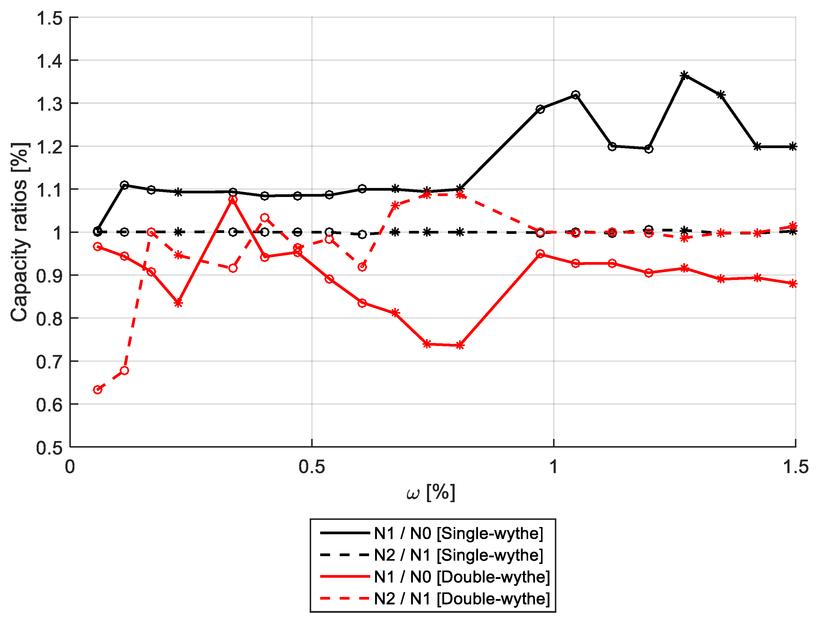
  • It was also observed that the axial load applied to the walls increased their out-of-plane capacity, particularly when the primary failure mode was textile damage.

Author Contributions

Conceptualization, L.A.S.K. and D.A.B.; methodology, L.A.S.K.; software, L.A.S.K. and S.P.T.; validation, L.A.S.K.; formal analysis, L.A.S.K. and F.A.K.; investigation, L.A.S.K.; writing—original draft preparation, L.A.S.K.; writing—review and editing, L.A.S.K., S.P.T. and D.A.B.; visualization, L.A.S.K.; supervision, D.A.B.; project administration, D.A.B.; funding acquisition, L.A.S.K. All authors have read and agreed to the published version of the manuscript.

Funding

This research was funded by Marie Skłodowska-Curie Individual Fellowship for the ‘SPEctRUM’ project (Programme/Call: H2020-MSCA-IF-2017; Proposal No: 799593—Seismic Plus EneRgy Upgrading of Masonry Buildings using Advanced Materials).

Data Availability Statement

Data is contained within the article.

Conflicts of Interest

The authors declare no conflict of interest.

References

  1. Indirli, M.; Kouris, L.A.S.; Formisano, A.; Borg, R.P.; Mazzolani, F.M. Seismic damage assessment of unreinforced masonry structures after the Abruzzo 2009 earthquake: The case study of the historical centers of L’Aquila and Castelvecchio Subequo. Int. J. Archit. Herit. 2013, 7, 536–578. [Google Scholar] [CrossRef]
  2. Gkournelos, P.D.; Triantafillou, T.C.; Bournas, D.A. Seismic upgrading of existing masonry structures: A state-of-the-art review. Soil Dyn. Earthq. Eng. 2022, 161, 107428. [Google Scholar] [CrossRef]
  3. Formisano, A.; Marzo, A. Simplified and refined methods for seismic vulnerability assessment and retrofitting of an Italian cultural heritage masonry building. Comput. Struct. 2017, 180, 13–26. [Google Scholar] [CrossRef]
  4. Maraveas, C.; Tasiouli, K. Assessment and restoration of the first Greek power plant—Registered monument of industrial heritage. Case Stud. Struct. Eng. 2015, 3, 1–10. [Google Scholar] [CrossRef]
  5. Davino, A.; Longobardi, G.; Meglio, E.; Dallari, A.; Formisano, A. Seismic Energy Upgrading of an Existing Brick Masonry Building by a Cold-Formed Steel Envelope System. Buildings 2022, 12, 1918. [Google Scholar] [CrossRef]
  6. Vintzileou, E.; Mouzakis, C.; Karapitta, L.; Miltiadou-Fezans, A. Shake-Table Testing of a Cross Vault. Buildings 2022, 12, 1984. [Google Scholar] [CrossRef]
  7. Maraveas, C. Assessment and Restoration of an Earthquake-Damaged Historical Masonry Building. Front. Built Environ. 2019, 5, 474447. [Google Scholar] [CrossRef]
  8. Penelis, G.G. Structural restoration of historical buildings in seismic areas. Prog. Struct. Eng. Mater. 2002, 4, 64–73. [Google Scholar] [CrossRef]
  9. Triantafillou, T.C.; Fardis, M.N. Strengthening of historic masonry structures with composite materials. Mater. Struct. Constr. 1997, 30, 486–496. [Google Scholar] [CrossRef]
  10. de Felice, G.; Aiello, M.A.; Caggegi, C.; Ceroni, F.; De Santis, S.; Garbin, E.; Gattesco, N.; Hojdys, Ł.; Krajewski, P.; Kwiecień, A.; et al. Recommendation of RILEM Technical Committee 250-CSM: Test method for Textile Reinforced Mortar to substrate bond characterization. Mater. Struct. Constr. 2018, 51, 1–9. [Google Scholar] [CrossRef]
  11. Kouris, L.A.S.; Triantafillou, T.C. State-of-the-art on strengthening of masonry structures with textile reinforced mortar (TRM). Constr. Build. Mater. 2018, 188, 1221–1233. [Google Scholar] [CrossRef]
  12. Kariou, F.A.; Triantafyllou, S.P.; Bournas, D.A. TRM strengthening of masonry arches: An experimental investigation on the effect of strengthening layout and textile fibre material. Compos. Part B Eng. 2019, 173, 106765. [Google Scholar] [CrossRef]
  13. Papanicolaou, C.; Triantafillou, T.; Lekka, M. Externally bonded grids as strengthening and seismic retrofitting materials of masonry panels. Constr. Build. Mater. 2011, 25, 504–514. [Google Scholar] [CrossRef]
  14. Cerniauskas, G.; Tetta, Z.; Bournas, D.A.; Bisby, L.A. Concrete confinement with TRM versus FRP jackets at elevated temperatures. Mater. Struct. 2020, 53, 58. [Google Scholar] [CrossRef]
  15. Triantafillou, T.C.; Karlos, K.; Kefalou, K.; Argyropoulou, E. An innovative structural and energy retrofitting system for URM walls using textile reinforced mortars combined with thermal insulation: Mechanical and fire behavior. Constr. Build. Mater. 2017, 133, 1–13. [Google Scholar] [CrossRef]
  16. Kapsalis, P.; El Kadi, M.; Vervloet, J.; De Munck, M.; Wastiels, J.; Triantafillou, T.; Tysmans, T. Thermomechanical Behavior of Textile Reinforced Cementitious Composites Subjected to Fire. Appl. Sci. 2019, 9, 747. [Google Scholar] [CrossRef]
  17. Bournas, D.A. Concurrent seismic and energy retrofitting of RC and masonry building envelopes using inorganic textile-based composites combined with insulation materials: A new concept. Compos. Part B Eng. 2018, 148, 166–179. [Google Scholar] [CrossRef]
  18. Pohoryles, D.A.; Maduta, C.; Bournas, D.A.; Kouris, L.A. Energy Performance of Existing Residential Buildings in Europe: A Novel Approach Combining Energy with Seismic Retrofitting. Energy Build. 2020, 223, 110024. [Google Scholar] [CrossRef]
  19. Valluzzi, M.R.; da Porto, F.; Garbin, E.; Panizza, M. Out-of-plane behaviour of infill masonry panels strengthened with composite materials. Mater. Struct. Constr. 2014, 47, 2131–2145. [Google Scholar] [CrossRef]
  20. Harajli, M.; ElKhatib, H.; San-Jose, J.T. Static and Cyclic Out-of-Plane Response of Masonry Walls Strengthened Using Textile-Mortar System. J. Mater. Civ. Eng. 2010, 22, 1171–1180. [Google Scholar] [CrossRef]
  21. Kariou, F.A.; Triantafyllou, S.P.; Bournas, D.A.; Koutas, L.N. Out-of-plane response of masonry walls strengthened using textile-mortar system. Constr. Build. Mater. 2018, 165, 769–781. [Google Scholar] [CrossRef]
  22. Papanicolaou, C.G.; Triantafillou, T.C.; Papathanasiou, M.; Karlos, K. Textile reinforced mortar (TRM) versus FRP as strengthening material of URM walls: Out-of-plane cyclic loading. Mater. Struct. 2008, 41, 143–157. [Google Scholar] [CrossRef]
  23. Babaeidarabad, S.; Nanni, A. Out-of-plane strengthening of URM walls with fabric-reinforced-cementitious-matrix (FRCM). In Proceedings of the American Concrete Institute, ACI Special Publication, Bologna, Italy, 1–3 October 2015; Volume 2015. [Google Scholar]
  24. Gkournelos, P.D.; Triantafillou, T.C.; Bournas, D.A. Integrated Structural and Energy Retrofitting of Masonry Walls: Effect of In-Plane Damage on the Out-of-Plane Response. J. Compos. Constr. 2020, 24. [Google Scholar] [CrossRef]
  25. Kouris, L.A.S.; Triantafillou, T.C. Design Methods for Strengthening Masonry Buildings Using Textile-Reinforced Mortar. J. Compos. Constr. 2019, 23. [Google Scholar] [CrossRef]
  26. Babaeidarabad, S.; De Caso, F.; Nanni, A. Out-of-Plane Behavior of URM Walls Strengthened with Fabric-Reinforced Cementitious Matrix Composite. J. Compos. Constr. 2014, 18, 04013057. [Google Scholar] [CrossRef]
  27. Mosallam, A.S. Out-of-plane flexural behavior of unreinforced red brick walls strengthened with FRP composites. Compos. Part B Eng. 2007, 38, 559–574. [Google Scholar] [CrossRef]
  28. Babatunde, S.A. Review of strengthening techniques for masonry using fiber reinforced polymers. Compos. Struct. 2017, 161, 246–255. [Google Scholar] [CrossRef]
  29. Nicoletti, V.; Arezzo, D.; Carbonari, S.; Gara, F. Vibration-Based Tests and Results for the Evaluation of Infill Masonry Walls Influence on the Dynamic Behaviour of Buildings: A Review. Arch. Comput. Methods Eng. 2022, 29, 3773–3787. [Google Scholar] [CrossRef]
  30. Furtado, A.; Rodrigues, H.; Arêde, A.; Varum, H. Experimental evaluation of out-of-plane capacity of masonry infill walls. Eng. Struct. 2016, 111, 48–63. [Google Scholar] [CrossRef]
  31. De Angelis, A.; Pecce, M.R. Out-of-plane structural identification of a masonry infill wall inside beam-column RC frames. Eng. Struct. 2018, 173, 546–558. [Google Scholar] [CrossRef]
  32. Kouris, L.A.S.; Penna, A.; Magenes, G. Dynamic Modification and Damage Propagation of a Two-Storey Full-Scale Masonry Building. Adv. Civ. Eng. 2019, 2019, 2396452. [Google Scholar] [CrossRef]
  33. Kouris, L.A.S.; Penna, A.; Magenes, G. Assessment of a Full-Scale Unreinforced Stone Masonry Building Tested on a Shaking Table by Inverse Engineering. Buildings 2022, 12, 1235. [Google Scholar] [CrossRef]
  34. Theodossopoulos, D.; Sinha, B. A review of analytical methods in the current design processes and assessment of performance of masonry structures. Constr. Build. Mater. 2013, 41, 990–1001. [Google Scholar] [CrossRef]
  35. Kouris, L.A.S.; Meireles, H.; Bento, R.; Kappos, A.J. Simple and complex modelling of timber-framed masonry walls in Pombalino buildings. Bull. Earthq. Eng. 2014, 12, 1–27. [Google Scholar] [CrossRef]
  36. Lagomarsino, S.; Penna, A.; Galasco, A.; Cattari, S. TREMURI program: An equivalent frame model for the nonlinear seismic analysis of masonry buildings. Eng. Struct. 2013, 56, 1787–1799. [Google Scholar] [CrossRef]
  37. Kouris, E.G.; Kouris, L.A.S. Investigation of the influence of tie-rods on the seismic behaviour of slender towers. Civil-Comp Proc. 2014, 106, 1–15. [Google Scholar] [CrossRef]
  38. Giordano, A.; Mele, E.; De Luca, A. Modelling of historical masonry structures: Comparison of different approaches through a case study. Eng. Struct. 2002, 24, 1057–1069. [Google Scholar] [CrossRef]
  39. Gambarotta, L.; Lagomarsino, S. Damage models for the seismic response of brick masonry shear walls. Part II: The continuum model and its applications. Earthq. Eng. Struct. Dyn. 1997, 26, 423–439. [Google Scholar] [CrossRef]
  40. Milani, G.; Lourenço, P.B.; Tralli, A. Homogenised limit analysis of masonry walls, Part II: Structural examples. Comput. Struct. 2006, 84, 181–195. [Google Scholar] [CrossRef]
  41. Zucchini, A.; Lourenço, P.B. A micro-mechanical homogenisation model for masonry: Application to shear walls. Int. J. Solids Struct. 2009, 46, 871–886. [Google Scholar] [CrossRef]
  42. Anthoine, A. Derivation of the in-plane elastic characteristics of masonry through homogenization theory. Int. J. Solids Struct. 1995, 32, 137–163. [Google Scholar] [CrossRef]
  43. Lourenço, P.B.; Milani, G.; Tralli, A.; Zucchini, A. Analysis of masonry structures: Review of and recent trends in homogenization techniquesThis article is one of a selection of papers published in this Special Issue on Masonry. Can. J. Civ. Eng. 2007, 34, 1443–1457. [Google Scholar] [CrossRef]
  44. Kouris, L.A.S.; Bournas, D.A.; Akintayo, O.T.; Konstantinidis, A.A.; Aifantis, E.C. A gradient elastic homogenisation model for brick masonry. Eng. Struct. 2020, 208, 110311. [Google Scholar] [CrossRef]
  45. Bertolesi, E.; Carozzi, F.G.; Milani, G.; Poggi, C. Numerical modeling of Fabric Reinforce Cementitious Matrix composites (FRCM) in tension. Constr. Build. Mater. 2014, 70, 531–548. [Google Scholar] [CrossRef]
  46. Parisi, F.; Lignola, G.P.; Augenti, N.; Prota, A.; Manfredi, G. Nonlinear Behavior of a Masonry Subassemblage Before and After Strengthening with Inorganic Matrix-Grid Composites. J. Compos. Constr. 2011, 15, 821–832. [Google Scholar] [CrossRef]
  47. Basili, M.; Marcari, G.; Vestroni, F. Nonlinear analysis of masonry panels strengthened with textile reinforced mortar. Eng. Struct. 2016, 113, 245–258. [Google Scholar] [CrossRef]
  48. Lignola, G.P.; Prota, A.; Manfredi, G. Nonlinear Analyses of Tuff Masonry Walls Strengthened with Cementitious Matrix-Grid Composites. J. Compos. Constr. 2009, 13, 243–251. [Google Scholar] [CrossRef]
  49. Basili, M.; Vestroni, F.; Marcari, G. Brick masonry panels strengthened with textile reinforced mortar: Experimentation and numerical analysis. Constr. Build. Mater. 2019, 227, 117061. [Google Scholar] [CrossRef]
  50. Wang, X.; Ghiassi, B.; Oliveira, D.V.; Lam, C.C. Modelling the nonlinear behaviour of masonry walls strengthened with textile reinforced mortars. Eng. Struct. 2017, 134, 11–24. [Google Scholar] [CrossRef]
  51. Loccarini, F.; Ranocchiai, G.; Rotunno, T.; Fagone, M. Experimental and numerical analyses of strengthened rammed earth masonry arches. Comput. Struct. 2020, 239, 106329. [Google Scholar] [CrossRef]
  52. Scacco, J.; Ghiassi, B.; Milani, G.; Lourenço, P.B. A fast modeling approach for numerical analysis of unreinforced and FRCM reinforced masonry walls under out-of-plane loading. Compos. Part B Eng. 2020, 180, 107553. [Google Scholar] [CrossRef]
  53. Kyriakides, M.A.; Billington, S.L. Behavior of unreinforced masonry prisms and beams retrofitted with engineered cementitious composites. Mater. Struct. Constr. 2014, 47, 1573–1587. [Google Scholar] [CrossRef]
  54. Kyriakides, M.A.; Hendriks, M.A.N.; Billington, S.L. Simulation of unreinforced masonry beams retrofitted with engineered cementitious composites in flexure. J. Mater. Civ. Eng. 2012, 24, 506–515. [Google Scholar] [CrossRef]
  55. Singh, S.B.; Patil, R.; Munjal, P. Study of flexural response of engineered cementitious composite faced masonry structures. Eng. Struct. 2017, 150, 786–802. [Google Scholar] [CrossRef]
  56. Munjal, P.; Singh, S.B. Out-of-plane response of ECC-strengthened masonry walls. J. Struct. Integr. Maint. 2020, 5, 18–30. [Google Scholar] [CrossRef]
  57. Leone, M.; Aiello, M.A.; Balsamo, A.; Carozzi, F.G.; Ceroni, F.; Corradi, M.; Gams, M.; Garbin, E.; Gattesco, N.; Krajewski, P.; et al. Glass fabric reinforced cementitious matrix: Tensile properties and bond performance on masonry substrate. Compos. Part B Eng. 2017, 127, 196–214. [Google Scholar] [CrossRef]
  58. Larrinaga, P.; Chastre, C.; Biscaia, H.C.; San-José, J.T. Experimental and numerical modeling of basalt textile reinforced mortar behavior under uniaxial tensile stress. Mater. Des. 2014, 55, 66–74. [Google Scholar] [CrossRef]
  59. Veljkovic, A.; Carvelli, V.; Rezazadeh, M. Modelling the bond in GFRP bar reinforced concrete thin structural members. Structures 2020, 24, 13–26. [Google Scholar] [CrossRef]
  60. Makashev, K.; Triantafyllou, S.P.; Thermou, G.E.; Tizani, W. Bond behaviour of light and heavy carbon fibre TRM to masonry interfaces. Constr. Build. Mater. 2023, 400, 132508. [Google Scholar] [CrossRef]
  61. Askouni, P.D.; Papanicolaou, C.G.; Azdejkovic, L. Experimental Investigation of the TRM-to-Masonry Bond after Exposure to Elevated Temperatures: Cementitious and Alkali-Activated Matrices of Various Densities. Materials 2022, 15, 140. [Google Scholar] [CrossRef]
  62. EN 1052-1; Methods of Test for Masonry-Part 1: Determination of Compressive Strength. European Committee for Standardization: Brussels, Belgium, 1999.
  63. Deng, M.; Yang, S. Experimental and numerical evaluation of confined masonry walls retrofitted with engineered cementitious composites. Eng. Struct. 2020, 207, 110249. [Google Scholar] [CrossRef]
  64. Kaushik, H.B.; Rai, D.C.; Jain, S.K. Stress-Strain Characteristics of Clay Brick Masonry under Uniaxial Compression. J. Mater. Civ. Eng. 2007, 19, 728–739. [Google Scholar] [CrossRef]
  65. Lubliner, J.; Oliver, J.; Oller, S.; Oñate, E. A plastic-damage model for concrete. Int. J. Solids Struct. 1989, 25, 299–326. [Google Scholar] [CrossRef]
  66. Lee, J.; Fenves, G.L. Plastic-Damage Model for Cyclic Loading of Concrete Structures. J. Eng. Mech. 1998, 124, 892–900. [Google Scholar] [CrossRef]
  67. Calderini, C.; Lagomarsino, S. Continuum model for in-plane anisotropic inelastic behavior of masonry. J. Struct. Eng. 2008, 134, 209–220. [Google Scholar] [CrossRef]
  68. Lotfi, H.R.; Shing, P.B. Interface model applied to fracture of masonry structures. J. Struct. Eng. 1994, 120, 63–80. [Google Scholar] [CrossRef]
  69. Gabor, A.; Ferrier, E.; Jacquelin, E.; Hamelin, P. Analysis and modelling of the in-plane shear behaviour of hollow brick masonry panels. Constr. Build. Mater. 2006, 20, 308–321. [Google Scholar] [CrossRef]
  70. Lourenço, P.B. Anisotropic softening model for masonry plates and shells. J. Struct. Eng. 2000, 126, 1008–1016. [Google Scholar] [CrossRef]
  71. Drougkas, A.; Roca, P.; Molins, C. Material Characterization and Micro-Modeling of a Historic Brick Masonry Pillar. Int. J. Archit. Herit. 2016, 10, 887–902. [Google Scholar] [CrossRef]
  72. Bedon, C.; Louter, C. Numerical investigation on structural glass beams with GFRP-embedded rods, including effects of pre-stress. Compos. Struct. 2018, 184, 650–661. [Google Scholar] [CrossRef]
  73. Stupkiewicz, S.; Mróz, Z. Modelling of friction and dilatancy effects at brittle interfaces for monotonic and cyclic loading | Stupkiewicz | Journal of Theoretical and Applied Mechanics. J. Theor. Appl. Mech. 2001, 39, 707–739. [Google Scholar]
  74. Lourenço, P.B.; Ramos, L.F. Characterization of cyclic behavior of dry masonry joints. J. Struct. Eng. 2004, 130, 779–786. [Google Scholar] [CrossRef]
  75. D’Antino, T.; Carloni, C.; Sneed, L.H.; Pellegrino, C. Matrix-fiber bond behavior in PBO FRCM composites: A fracture mechanics approach. Eng. Fract. Mech. 2014, 117, 94–111. [Google Scholar] [CrossRef]
  76. Askouni, P.D.; Papanicolaou, C.G. Textile Reinforced Mortar-to-masonry bond: Experimental investigation of bond-critical parameters. Constr. Build. Mater. 2019, 207, 535–547. [Google Scholar] [CrossRef]
  77. Askouni, P.D.; Papanicolaou, C.G. Experimental investigation of bond between glass textile reinforced mortar overlays and masonry: The effect of bond length. Mater. Struct. Constr. 2017, 50, 164. [Google Scholar] [CrossRef]
  78. Banholzer, B.; Brockmann, T.; Brameshuber, W. Material and bonding characteristics for dimensioning and modelling of textile reinforced concrete (TRC) elements. Mater. Struct. 2006, 39, 749–763. [Google Scholar] [CrossRef]
  79. Alecci, V.; De Stefano, M.; Luciano, R.; Rovero, L.; Stipo, G. Experimental Investigation on Bond Behavior of Cement-Matrix–Based Composites for Strengthening of Masonry Structures. J. Compos. Constr. 2016, 20, 04015041. [Google Scholar] [CrossRef]
  80. CEB-FIB. Model Code 2010-First Complete Draft; International Federation for Structural Concrete (fib): Lausanne, Switzerland, 2010; Volume 1, ISBN 978-2-88394-095-6. [Google Scholar]
Figure 1. Test set-up and dimensions: (a) side view of the single-wythe specimens; (b) side view of the double-wythe specimens; (c) top view.
Buildings 14 00032 g001
Figure 2. The compressive stress–plastic strain curve of masonry employed in the CDP constitutive model.
Buildings 14 00032 g002
Figure 3. Comparison of the out-of-plane response of the unreinforced double-wythe specimen with the analytical model.
Buildings 14 00032 g003
Figure 4. The traction separation law of the joint interfaces.
Buildings 14 00032 g004
Figure 5. A trilinear stress–strain curve of TRM, typically employed in finite element analysis, and a the effective linear one.
Buildings 14 00032 g005
Figure 6. The modelling approach for bond slip phenomena in TRM: (a) linear textile response, (b) bilinear bonding response, and (c) the resulting effective linear textile response.
Buildings 14 00032 g006
Figure 7. Comparison of the out-of-plane response of the reinforced single-wythe specimen with the analytical model.
Buildings 14 00032 g007
Figure 8. Comparison of the out-of-plane response of the reinforced double wythe specimen with the analytical model.
Buildings 14 00032 g008
Figure 9. Plastic strain at the final step of the analysis and damaged specimens.
Buildings 14 00032 g009aBuildings 14 00032 g009b
Figure 10. Geometric features of a double-layer (n = 2) TRM jacket: yarn radius r, textile nominal thickness tnom, distance w between yarns, thickness hL of layers and thickness of TRM jacket tcoat.
Buildings 14 00032 g010
Figure 11. Experimental vs. estimated values of Ω.
Buildings 14 00032 g011
Figure 12. The surfaces of the empirical curve ΩΕ vs. the experimental calibrated values: (a) carbon, (b) glass, and (c) basalt.
Buildings 14 00032 g012
Figure 13. Variation in (a) ΩΕ vs. α, and (b) ΩΕ vs. β (see Equation (18)).
Buildings 14 00032 g013
Figure 14. Textile properties for parametric analyses with varying mechanical ratios combining a range of textile strengths, yarn area (area of the points), and number of layers (colour of the points, see colour bar) vs. (a) textile tensile force and (b) textile tensile strength.
Buildings 14 00032 g014
Figure 15. Maximum vertical load of piers out-of-plane loaded for 3 levels of axial load: (a) N = 0, (b) N = 10% fm, and (c) N = 20% fm; damage of masonry (*) and textile failure (o).
Buildings 14 00032 g015
Figure 16. Out-of-plane capacity ratios of the strengthened piers (coated) for the 3 levels of axial load: (i) N = 0 (N0), (ii) N = 10% fm (N1), and (iii) N = 20% fm (N2); damage of masonry (*) and textile failure (o) of N0 piers.
Buildings 14 00032 g016
Table 1. Material properties: elastic modulus (GPa) and strength (MPa).
MaterialStrengthElastic Modulus
Masonry9.72.5
Brick units12.3-
Casting mortar (joints)7.5 compressive/2.2 tensile-
Reinforcing mortar (matrix)39.7 compressive/+9.0 tensile0.8
Carbon3800225
Glass140074
Basalt (coated)135189
Table 2. Main experimental parameters and results from [21].
SpecimentcoatρwωtMax ForceMax DisplacementFailure Mode *
(mm)(%) (kN)(mm)
S_C130.095%0.3523.415.6TX(DB,SL)
S_C1_(Co)50.095%0.3535.320.8TX(FB)
S_G340.129%0.1914.312.2TX(FB)
S_G3_(Co)70.129%0.1925.830TX(FB)
S_G780.300%0.4330.614.7TX(FB)
S_G7_(Co)90.300%0.4342.555MR(SD,FL) + TX(DB)
S_B3_(Co)90.108%0.1523.224.7TX(FB)
S_B7_(Co)130.253%0.3544.532.1MR(SD,FL), TX(DB)
D_C130.045%0.1740.19.7TX(FB)
D_C1_(Co)50.045%0.1758.814.9MR(SD,SV,FL), TX(FB)
D_G340.061%0.09325.8TX(FB)
D_G3_(Co)70.061%0.0940.428.8MR(SD,FL), TX(DB)
D_G780.143%0.0367.112.8MR(SD,FL), TX(FB)
D_G7_(Co)90.143%0.2163.816.2MR(SD,FL), TX(DB)
D_B3_(Co)90.052%0.0743.116.7MR(SD,SV,FL), TX(FB)
D_B7_(Co)130.120%0.1766.213.6MR(SD)
* TX = textile failure (DB = textile debonding; FB = fibre breakage; SL = textile slippage). MR = masonry failure (FL = flexural failure; SD = shear with diagonal cracks; SV = shear vertical sliding).
Table 3. Calibrated material parameters of the CDP model.
  ψ   ϵ σb0c0Kμ
(deg)(%)(-)(-)(-)
1501.162/310−6
Table 4. Effective elastic modulus Eeff, effective strength feff, stress of the composite σt, and corresponding reduction factors ΩΕ and Ωf.
ModelEeff
(GPa)
feff
(GPa)
σt
(MPa)
ΩEΩf
S_C1140127012700.620.33
S_C1_(Co)214247024700.950.62
S_G3425325050.570.38
S_G3_(Co)5210109600.700.72
S_G7616236230.820.44
S_G7_(Co)63102210220.850.71
S_B3429508170.470.70
S_B7679599110.750.71
D_C15610456270.250.29
D_C1_(Co)110247014820.490.75
D_G3425563340.570.40
D_G3_(Co)3410089070.460.74
D_G7335504950.450.39
D_G7_(Co)359809310.470.79
D_B3269464730.290.88
D_B7299463780.330.88
Table 5. Calibrated values of the parameters in Equation (18).
p1p2p3R2p-Value
ΩΕ (uncoated)0.635590.120.853 × 10−3
ΩΕ (coated)0.1515570.120.842 × 10−3
Ωf (uncoated)2.3420000.130.932 × 10−3
Ωf (coated)3.352770.060.941 × 10−3
Disclaimer/Publisher’s Note: The statements, opinions and data contained in all publications are solely those of the individual author(s) and contributor(s) and not of MDPI and/or the editor(s). MDPI and/or the editor(s) disclaim responsibility for any injury to people or property resulting from any ideas, methods, instructions or products referred to in the content.

