
Experimental Investigation on the Axial Loading Performance of Grooving-Damaged Square Hollow Concrete-Filled Steel Tube Columns


Abstract
:1. Introduction
2. Experimental Study
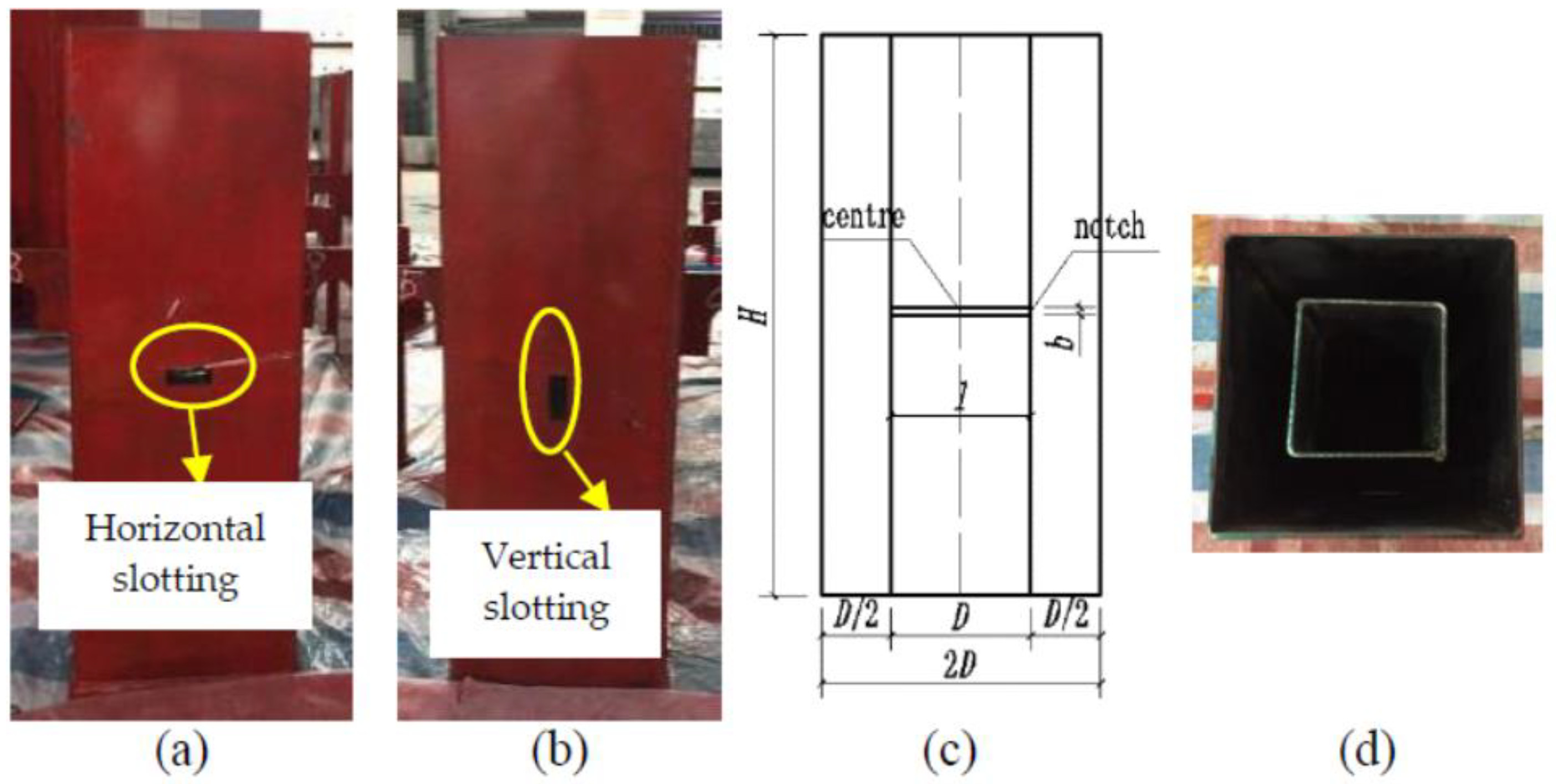
2.1. Test Design
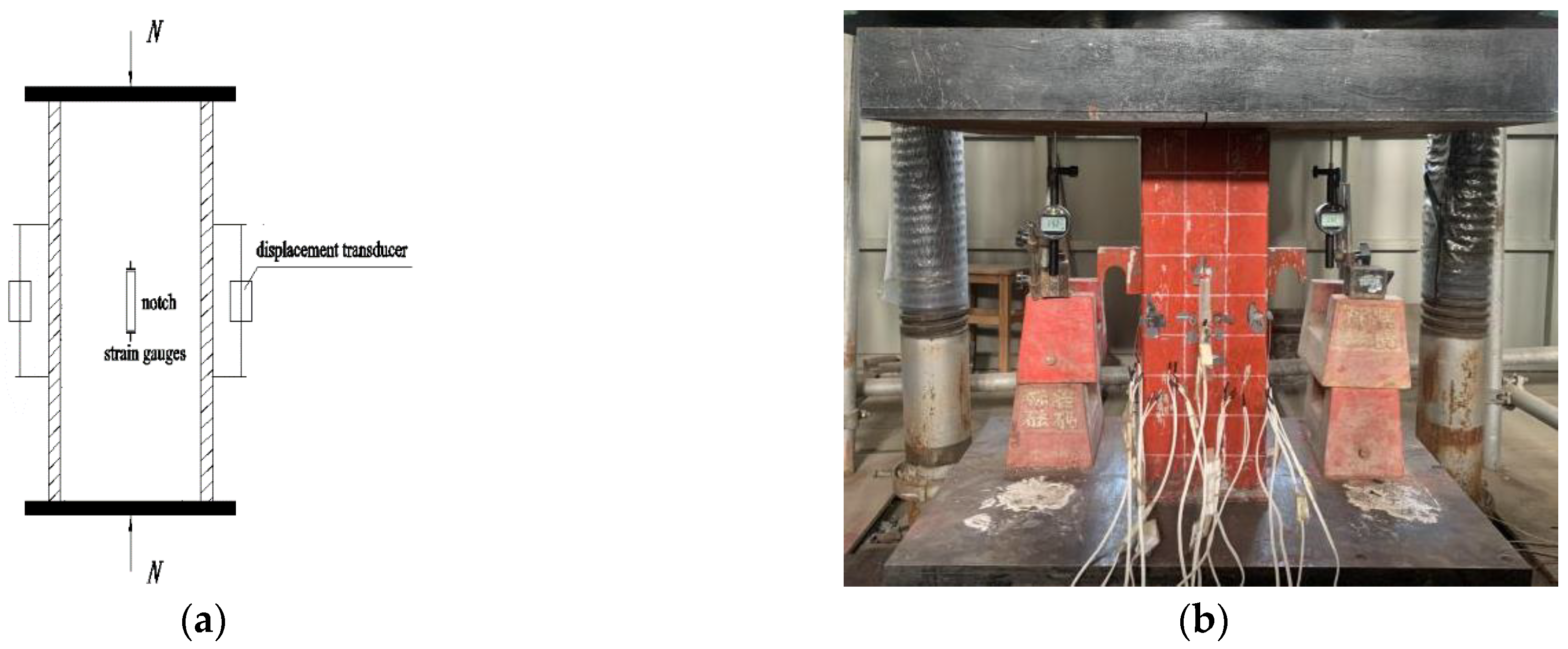
2.2. Loading Scheme
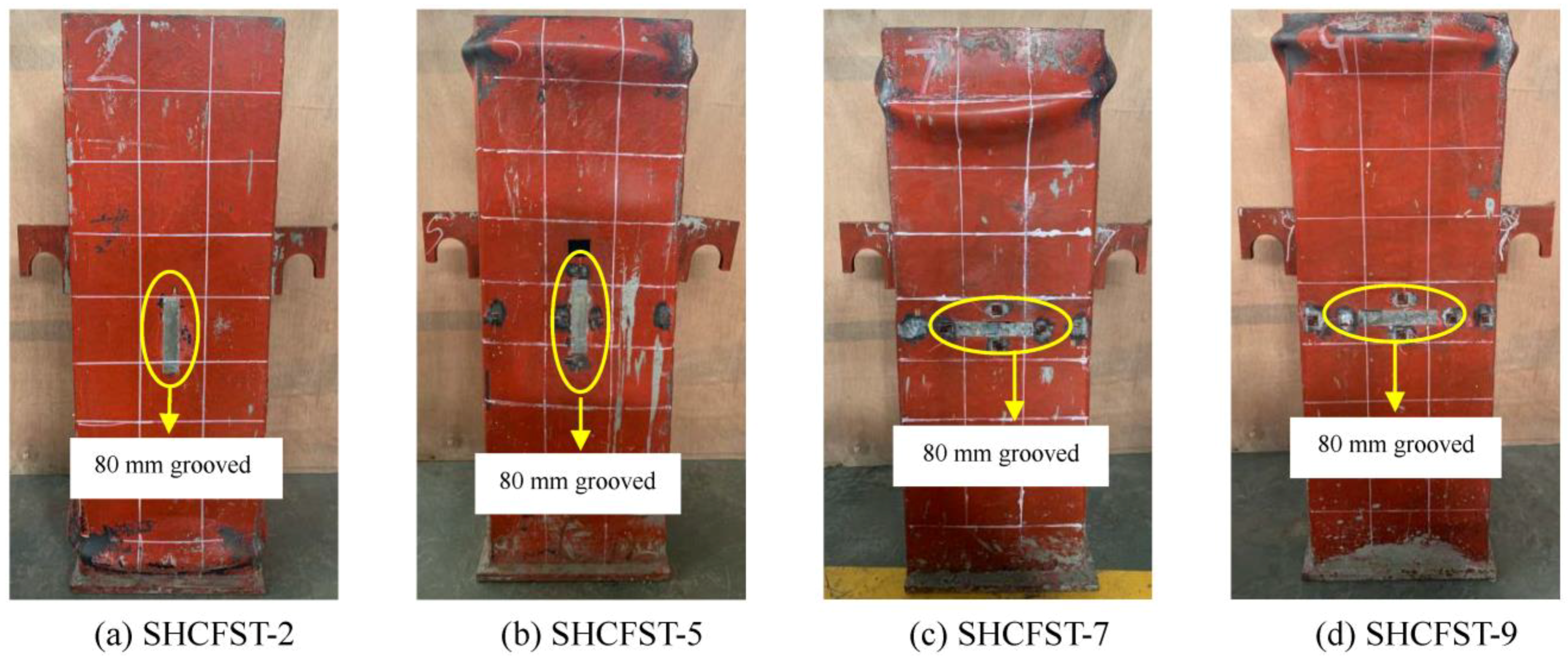
2.3. Loading Phenomenon
2.4. Analysis of Test Results
3. Effects of Three Parameters on the Axial Compression Performance of SHCFST Columns
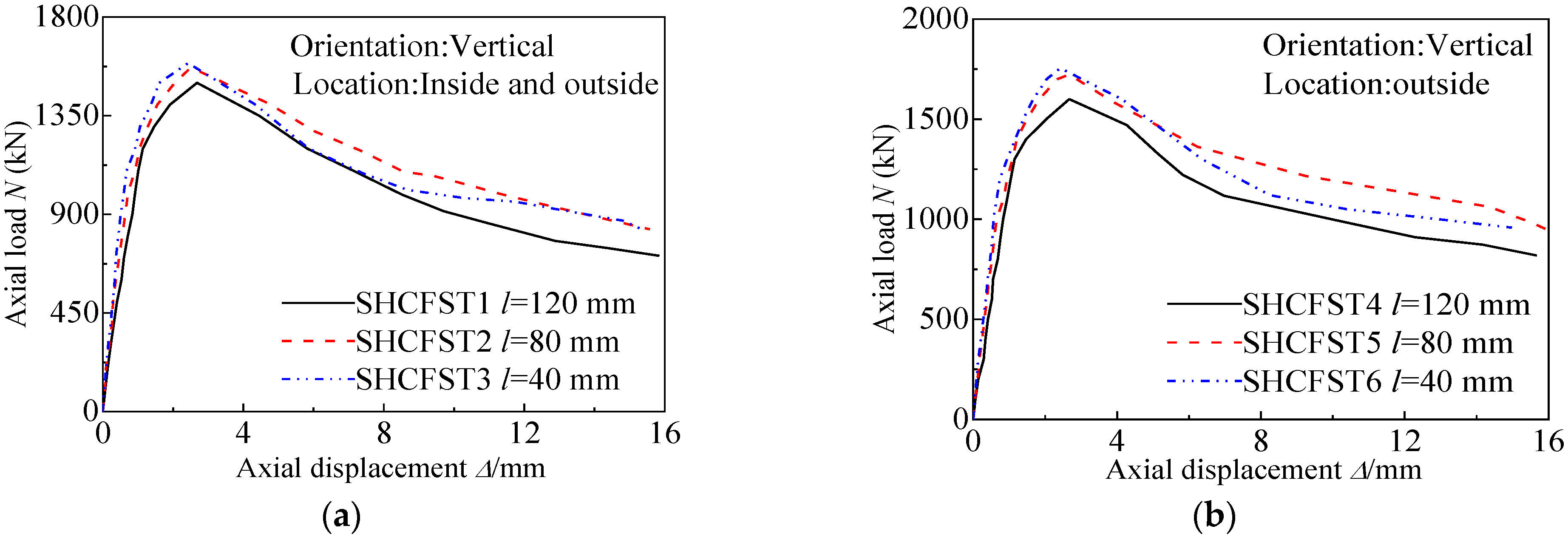
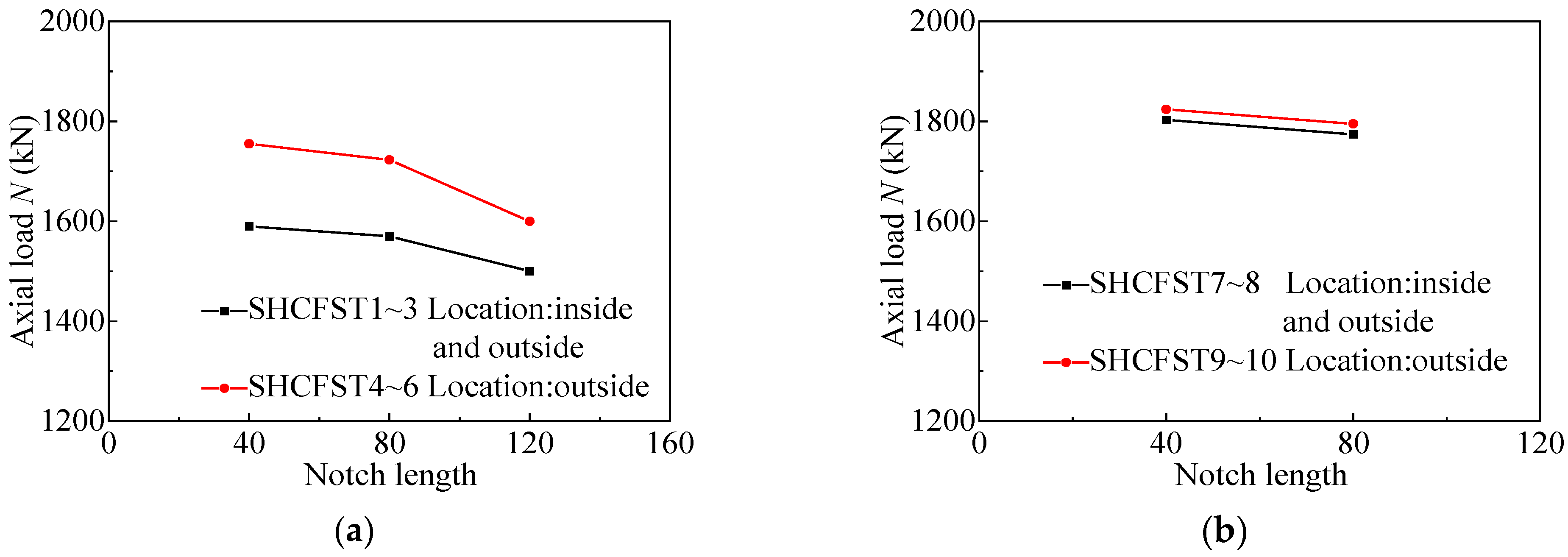
3.1. Influence of Notch Length
3.2. Influence of Notch Location
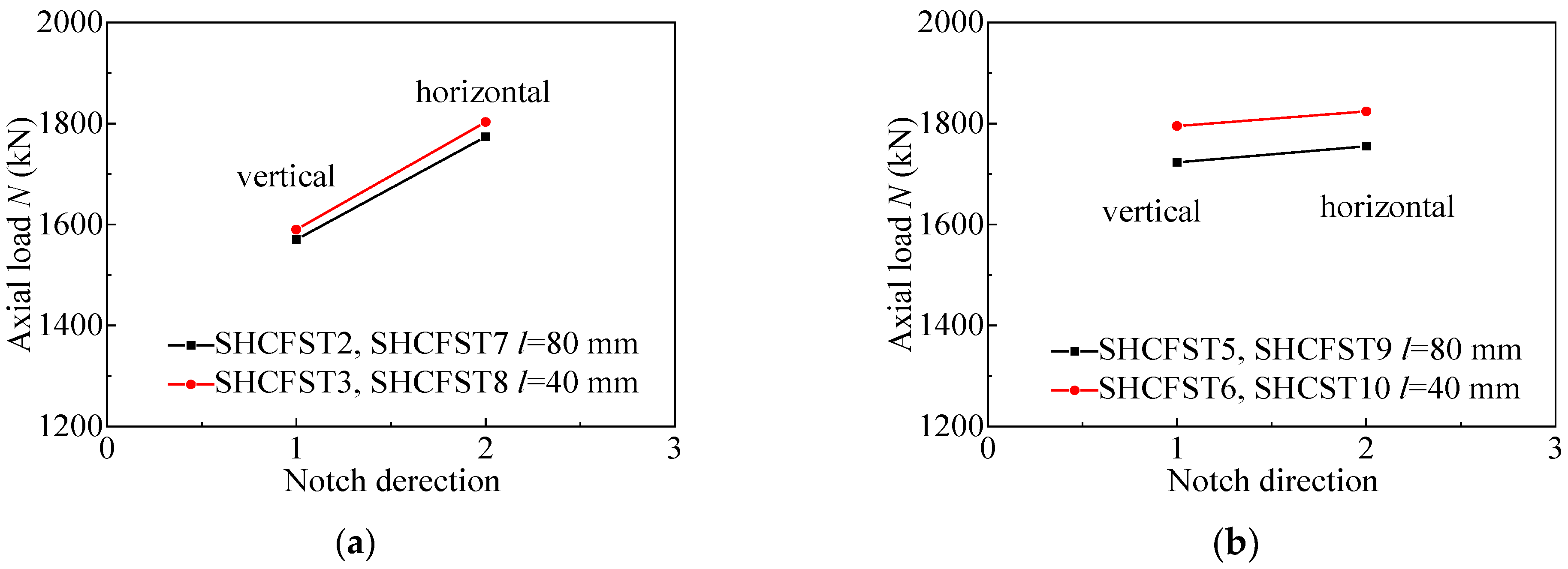
3.3. Influence of Notch Direction
4. Calculation of the Ultimate Bearing Capacity and Axial Compression Stiffness of Notched SHCFST Columns
4.1. Bearing Strength
4.2. Confinement Effect
4.3. Axial Compression Stiffness
5. Conclusions
- (1)
- The test results indicate that at the early stage of the elastic phase, no remarkable buckling or other deformations are present on the surface of the specimen. Different types of CFST columns exhibit the same failure modes. That is, all specimens experience buckling phenomenon at their top or bottom. After the completion of the experiments, the steel tube of the specimens was cut and stripped, which revealed the core concrete had different degrees of damage. The concrete core failure of the specimens with inner and outer steel tube grooves was more obvious than that of the specimens with only outer steel tube grooves;
- (2)
- The ultimate load-bearing capacity of grooved CFST columns is lower than that of intact CFST columns because grooved steel tubes cannot provide sufficient constraint to the concrete core within the column. Parameter analysis reveals that groove length and width, position, and direction have a certain effect on the strength of concrete columns in grooved steel tubes. It can be observed that as the groove length increases, the steel tube’s constraining effect weakens, leading to the low ultimate load-bearing capacity of the specimens. When the inner and outer steel tubes are slotted, the ultimate bearing capacity of the SHCFST column is smaller than that when only the outer steel tube is slotted. The load-bearing capacity of specimens with horizontal grooves is greater than that of specimens with vertical grooves;
- (3)
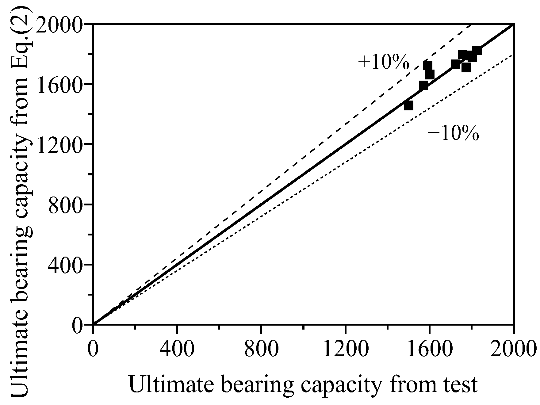
- The ultimate load-bearing capacity of undamaged SHCFST columns was predicted by using existing formulas. An empirical equation based on the formula proposed by Ding et al. [18] was established to predict the ultimate load-bearing capacity of grooved SHCFST columns. The calculated values align well with the experimental results. This work also proposes the confinement effect. Experiments indicate that grooving has a considerable influence on structural load-bearing capacity and has a nonlinear relationship;
- (4)
- The influence of damage caused by grooving in steel tubes is considered, and a formula for calculating the axial compression stiffness of the specimens is proposed. The calculation results are in good agreement with the experimental results.
Author Contributions
Funding
Data Availability Statement
Conflicts of Interest
References
- Zhou, X.H.; Cheng, G.Z.; Liu, J.P.; Gan, D.; Chen, Y.F. Behavior of circular tubed-RC column to RC beam connections under axial compression. J. Constr. Steel Res. 2017, 130, 96–108. [Google Scholar] [CrossRef]
- Tian, C.Y.; Xiao, C.Z.; Chen, T.; Fu, X.Y. Experimental study on through beam connection system for concrete filled steel tube column-RC beam. Steel Compos. Struct. 2014, 16, 187–201. [Google Scholar] [CrossRef]
- He, S.H.; Zhou, W.J.; Jiang, Z.; Zheng, C.; Mo, X.; Huang, X. Structural performance of perforated steel plate-CFST arch feet in concrete girder-steel arch composite bridges. J. Constr. Steel Res. 2023, 201, 107742. [Google Scholar] [CrossRef]
- Zarringol, M.; Chen, Y.; Wang, Y.; Jiang, M.Y. Application of machine learning models for designing CFCFST columns. J. Constr. Steel Res. 2021, 185, 106856. [Google Scholar] [CrossRef]
- He, S.H.; Fang, Z.; Mosallam, A.M.; Ou, Y.Y.; Zou, C. Behavior of CFSC encased shear connectors in steel-concrete joints: Push-out tests. J. Struct. Eng. 2020, 146, 04020015. [Google Scholar] [CrossRef]
- Zhu, X.J.; Lu, J.F.; Hou, S.M. Experimental study on axial compression of notched concrete filled steel column. In Proceedings of the 7th National Conference on Structural Engineering (Vol. Ⅱ), Shijiazhuang, China, 2 July 1998; pp. 218–222. [Google Scholar]
- Yu, Z.Y.; Ding, F.X.; Cai, C.S. Experimental behavior of circular concrete-filled steel tube stub columns. J. Constr. Steel Res. 2007, 63, 165–174. [Google Scholar] [CrossRef]
- Chen, Z.P.; Zhong, M.; Chen, Y.L. Experimental study on mechanical properties of concretefilled opening hole damaged steel tubular members. Ind. Constr. 2013, 43, 121–127. (In Chinese) [Google Scholar]
- Chang, X.; Fu, L.; Zhao, H.B.; Zhang, Y.B. Behaviors of axially loaded circular concrete-filled steel tube (CFT) stub columns with notch in steel tubes. Thin-Walled Struct. 2013, 73, 273–280. [Google Scholar] [CrossRef]
- Liu, J.; Li, Z.; Ding, F.X. Experimental investigation on the axially loaded performance of notched hexagonal concrete-filled steel tube (CFST) column. Adv. Civ. Eng. 2019, 2019, 2612536. [Google Scholar] [CrossRef]
- Guo, L.H.; Huang, H.J.; Chen, J.; Romanov, K. Axial behavior of square CFST with local corrosion simulated by artificial notch. J. Constr. Steel Res. 2020, 174, 106314. [Google Scholar] [CrossRef]
- Han, L.H.; Hou, C.; Wang, Q.L. Square concrete filled steel tubular (CFST) members under loading and chloride corrosion: Experiments. J. Constr. Steel Res. 2012, 71, 11–25. [Google Scholar] [CrossRef]
- Alzand, A.W.; Badaruzzaman, W.H.W.; Shaikhli, M.S.; Ali, M.M. Flexural performance of square concrete-filled steel tube beams stiffened with V-shaped grooves. J. Constr. Steel Res. 2020, 166, 105930. [Google Scholar] [CrossRef]
- Wei, Y.; Zhu, C.; Miao, K.T.; Cai, J.L.; Zheng, K.Q. Compressive behavior of rectangular concrete-filled fiber-reinforced polymer and steel composite tube columns with stress-release grooves. Compos. Struct. 2022, 281, 114983. [Google Scholar] [CrossRef]
- Zhao, X.L.; Grzebieta, R. Strength and ductility of concrete filled double skin (SHS inner and SHS outer) tubes. Thin-Walled Struct. 2002, 40, 199–213. [Google Scholar] [CrossRef]
- Ayough, P.; Sulong, N.H.R.; Ibrahim, Z.; Hsiao, P.C. Nonlinear analysis of square concrete-filled double-skin steel tubular columns under axial compression. Eng. Struct. 2020, 216, 110678. [Google Scholar] [CrossRef]
- Rizwan, M.; Liang, Q.Q.; Hadi, M.N.S. Fiber-based computational modeling of rectangular double-skin concrete-filled steel tubular short columns including local buckling. Eng. Struct. 2021, 248, 113268. [Google Scholar] [CrossRef]
- Ding, F.X.; Wang, W.J.; Lu, D.R. Study on the behavior of concrete-filled square double-skin steel tubular stub columns under axial loading. Structures 2020, 23, 665–676. [Google Scholar] [CrossRef]
- Guo, Z.; Chen, Y.; Wang, Y.; Jiang, M.Y. Experimental study on square concrete-filled double skin steel tubular short columns. Thin-Walled Struct. 2020, 156, 107017. [Google Scholar] [CrossRef]


| No. | Orientation | Location | L × b (mm) | D × t × H (mm) | fs (MPa) | fcu (MPa) | Nt (kN) | Nc (kN) | |
|---|---|---|---|---|---|---|---|---|---|
| 1 | SHCFST-1 | Vertical | Inside and outside | 120 × 16 | 200 × 2.8 × 600 | 359 | 29.6 | 1500 | 1458.8 |
| 2 | SHCFST-2 | Vertical | Inside and outside | 80 × 16 | 200 × 2.8 × 600 | 359 | 29.6 | 1570 | 1591.8 |
| 3 | SHCFST-3 | Vertical | Inside and outside | 40 × 16 | 200 × 2.8 × 600 | 359 | 29.6 | 1590 | 1724.8 |
| 4 | SHCFST-4 | Vertical | Outside | 120 × 16 | 200 × 2.8 × 600 | 359 | 29.6 | 1600 | 1665.0 |
| 5 | SHCFST-5 | Vertical | Outside | 80 × 16 | 200 × 2.8 × 600 | 359 | 29.6 | 1723 | 1731.5 |
| 6 | SHCFST-6 | Vertical | Outside | 40 × 16 | 200 × 2.8 × 600 | 359 | 29.6 | 1755 | 1798.0 |
| 7 | SHCFST-7 | Horizontal | Inside and outside | 80 × 16 | 200 × 2.8 × 600 | 359 | 29.6 | 1774 | 1711.5 |
| 8 | SHCFST-8 | Horizontal | Inside and outside | 40 × 16 | 200 × 2.8 × 600 | 359 | 29.6 | 1803 | 1778.0 |
| 9 | SHCFST-9 | Horizontal | Outside | 80 × 16 | 200 × 2.8 × 600 | 359 | 29.6 | 1795 | 1791.3 |
| 10 | SHCFST-10 | Horizontal | Outside | 40 × 16 | 200 × 2.8 × 600 | 359 | 29.6 | 1824 | 1824.6 |
| No. | (mm2) | (kN) | (kN) | (kN) | λ |
|---|---|---|---|---|---|
| SHCFST-1 | 2016.0 | 1348.5 | 1458.8 | 110.3 | 0.076 |
| SHCFST-2 | 2464.0 | 1509.3 | 1591.8 | 82.5 | 0.052 |
| SHCFST-3 | 2912.0 | 1670.1 | 1724.8 | 54.7 | 0.032 |
| SHCFST-4 | 2688.0 | 1589.7 | 1665.0 | 75.3 | 0.045 |
| SHCFST-5 | 2912.0 | 1670.1 | 1731.5 | 61.4 | 0.035 |
| SHCFST-6 | 3136.0 | 1750.5 | 1798.0 | 47.5 | 0.026 |
| SHCFST-7 | 2464.0 | 1509.3 | 1711.5 | 202.2 | 0.118 |
| SHCFST-8 | 2912.0 | 1670.1 | 1778.0 | 107.9 | 0.061 |
| SHCFST-9 | 3136.0 | 1750.5 | 1791.3 | 40.8 | 0.023 |
| SHCFST-10 | 3248.0 | 1790.8 | 1824.6 | 33.8 | 0.019 |
| No. | (Pa) | (Pa) | (mm2) | (EA)c (N) | (EA)t (N) | (EA)c/(EA)t | |
|---|---|---|---|---|---|---|---|
| SHCFST-1 | 2.06 × 10¹¹ | 3.35 × 10¹⁰ | 2016.0 | 30,000 | 1.420 × 10⁹ | 1.11 × 10⁹ | 0.821 |
| SHCFST-2 | 2.06 × 10¹¹ | 3.35 × 10¹⁰ | 2464.0 | 30,000 | 1.513 × 10⁹ | 1.52 × 10⁹ | 1.006 |
| SHCFST-3 | 2.06 × 10¹¹ | 3.35 × 10¹⁰ | 2912.0 | 30,000 | 1.605 × 10⁹ | 1.89 × 10⁹ | 1.179 |
| SHCFST-4 | 2.06 × 10¹¹ | 3.35 × 10¹⁰ | 2688.0 | 30,000 | 1.559 × 10⁹ | 1.23 × 10⁹ | 0.817 |
| SHCFST-5 | 2.06 × 10¹¹ | 3.35 × 10¹⁰ | 2912.0 | 30,000 | 1.605 × 10⁹ | 1.59 × 10⁹ | 0.991 |
| SHCFST-6 | 2.06 × 10¹¹ | 3.35 × 10¹⁰ | 3136.0 | 30,000 | 1.651 × 10⁹ | 1.75 × 10⁹ | 1.060 |
| SHCFST-7 | 2.06 × 10¹¹ | 3.35 × 10¹⁰ | 2464.0 | 30,000 | 1.513 × 10⁹ | 1.25 × 10⁹ | 0.826 |
| SHCFST-8 | 2.06 × 10¹¹ | 3.35 × 10¹⁰ | 2912.0 | 30,000 | 1.605 × 10⁹ | 1.60 × 10⁹ | 0.991 |
| SHCFST-9 | 2.06 × 10¹¹ | 3.35 × 10¹⁰ | 3136.0 | 30,000 | 1.651 × 10⁹ | 1.21 × 10⁹ | 0.815 |
| SHCFST-10 | 2.06 × 10¹¹ | 3.35 × 10¹⁰ | 3248.0 | 30,000 | 1.674 × 10⁹ | 1.67 × 10⁹ | 0.996 |
Disclaimer/Publisher’s Note: The statements, opinions and data contained in all publications are solely those of the individual author(s) and contributor(s) and not of MDPI and/or the editor(s). MDPI and/or the editor(s) disclaim responsibility for any injury to people or property resulting from any ideas, methods, instructions or products referred to in the content. |
© 2023 by the authors. Licensee MDPI, Basel, Switzerland. This article is an open access article distributed under the terms and conditions of the Creative Commons Attribution (CC BY) license (https://creativecommons.org/licenses/by/4.0/).
Share and Cite
Liu, J.; Pan, Z.; Pan, Z.; He, S.; Yu, W. Experimental Investigation on the Axial Loading Performance of Grooving-Damaged Square Hollow Concrete-Filled Steel Tube Columns. Buildings 2024, 14, 87. https://doi.org/10.3390/buildings14010087
Liu J, Pan Z, Pan Z, He S, Yu W. Experimental Investigation on the Axial Loading Performance of Grooving-Damaged Square Hollow Concrete-Filled Steel Tube Columns. Buildings. 2024; 14(1):87. https://doi.org/10.3390/buildings14010087
Chicago/Turabian StyleLiu, Jing, Zimao Pan, Zhicheng Pan, Shaohua He, and Wenzhuo Yu. 2024. "Experimental Investigation on the Axial Loading Performance of Grooving-Damaged Square Hollow Concrete-Filled Steel Tube Columns" Buildings 14, no. 1: 87. https://doi.org/10.3390/buildings14010087
APA StyleLiu, J., Pan, Z., Pan, Z., He, S., & Yu, W. (2024). Experimental Investigation on the Axial Loading Performance of Grooving-Damaged Square Hollow Concrete-Filled Steel Tube Columns. Buildings, 14(1), 87. https://doi.org/10.3390/buildings14010087