Article

A Study on the Influence of Hydraulic Compactor Reinforcement on the Force Law of an Independent Foundation Under a Column and Its Safety Standard

1
School of Law and Humanities, China University of Mining and Technology-Beijing, Beijing 102208, China
2
China Construction Eighth Bureau First Company, Jinan 250100, China
3
College of Civil Engineering and Architecture, Shandong University of Science and Technology, Qingdao 266590, China
*
Author to whom correspondence should be addressed.
Buildings 2024, 14(11), 3331; https://doi.org/10.3390/buildings14113331
Submission received: 29 August 2024 / Revised: 15 October 2024 / Accepted: 18 October 2024 / Published: 22 October 2024
(This article belongs to the Section Building Structures)

Abstract

:
Due to the complexity of the actual geotechnical environment, the backfill compaction design theory and calculation method are not reflected in the current specification. Therefore, in order to investigate the effect of the hydraulic compactor on the foundation structure during the treatment of the backfill of an independent foundation under a column, the Menard formula was modified. At the same time, relying on an independent foundation project under a column in Jinan, the dynamic model of compactor tamping backfilling soil was established. The applicability of the calculation formula is verified by simulating the single-point multiple tamping on the backfill directly above the foundation tie beam, and the influence law of two factors, the thickness of the backfill and the tamping energy, on the force of the foundation tie beam is elucidated. The results show that after reaching the optimum number of tamping, the cumulative soil settlement and the effective reinforcement depth of tamping show a stable trend, and their simulation results are in good agreement with the analytical solution, which provides a supplement to the relevant safety standards. At this critical point, the force on the tie beams peaked and showed up and down fluctuations under the subsequent ramming action. The tamping action of the compactor has a significant effect on the structural forces within the effective reinforcement range, and there is a negative correlation between the magnitude of the structural forces and the thickness of the backfill. According to the numerical calculation results to choose the best construction programme, the on-site monitoring shows that under 42 KJ tamping energy and 1.5 m single backfilling thickness, the tie beam reinforcement stress reaches 18.5~55.5% of the specification warning value, which meets the safety standard. The research results of this paper can provide important guidance for the hydraulic tamping treatment of an independent foundation backfill project.

1. Introduction

An independent foundation under a frame column is widely used in foundation design due to its advantages of convenient construction, low project cost and short construction time [1,2,3,4]. In this type of foundation, methods such as sheep’s foot mill, frog tampers and manual tamping have traditionally been used to tamp the fill [5,6,7], but these methods suffer from low construction efficiency and poor tamping results, leading to many challenges in engineering practice. Hydraulic tampers are widely used in foundation tamping projects such as bridge abutment backs, culvert sides, railway roadbeds and other foundation tamping projects due to their manoeuvrability, flexibility, speed and efficiency. Despite the fact that hydraulic tampers are characterised by high impact frequency, light action and low peak forces compared to traditional tamping methods, the vibratory impact on nearby structures during tamping operations cannot be ignored.
To this end, Gu et al. [8] investigated the soil deformation law at special points through experimental data and preliminarily explored the influencing factors of the effective reinforcement depth of strong tamping and its influence law. Ji et al. [9] investigated the dynamic effect of hydraulic ramming on the back of bridge abutments and the propagation law of ramming energy through model tests, and they clarified that the ramming effect on shallow roadbed soil is shown as vertical impact, while the deep soil is shown as lateral extrusion. Miao et al. [10] studied the effect of different paving thicknesses and the number of tamping passes on the compaction effect by means of hydraulic tamping field tests; they also analysed operational efficiency under different process parameters. Liu et al. [11] analysed the effect of factors such as the number of ramming strokes and ramming position on culvert safety during hydraulic ramming based on field displacement monitoring data. Hu et al. [12] introduced the hydraulic loading coefficient and established a ramming model for the hydraulic ramming method, and the relationship between the peak acceleration of the ramming hammer and the amount of settlement of the topsoil under different working conditions was obtained by indoor foot-scale model experiments. Han et al. [13] carried out on-site reinforcement tests on gravel roadbeds using hydraulic ramming machines, analysed the parameters of the roadbeds before and after reinforcement, and established a compaction degree of roadbeds within the depth of the effective reinforcement prediction model. Feng et al. [14] combined field tests and ADINA numerical calculations to analyse the implementation of hydraulic ramming on the back of motorway platforms under different working conditions and found that the impact load has a more significant effect on the forces on the bridge abutment structures and that the impact loads are transmitted in a figure of an eight pattern from the ramming area downwards. Zhang et al. [15] proposed a shear design method considering the foundation aspect ratio and the relative stiffness of rock and foundation by combining field tests and numerical simulation; they also analysed the influencing factors of the shear bearing capacity of independent foundation under columns on rocky foundation. Li et al. [16] investigated the damage modes and mechanical properties of foundation specimens with different aspect ratios by comparing and analysing the results of numerical simulations with those of indoor tests and found that the damage was a result of the combined action of bending tensile stresses and lateral expansion and circumferential tensile stresses caused by vertical compression. Zhou et al. [17] monitored and calculated the force changes of the tie beams of the independent foundation and the frame columns under the columns by on-site monitoring and compared and analysed the on-site monitoring data with numerical simulation to study the effects of the backfilling process of the independent foundation on the columns and the frame structure. Zhang et al. [18], based on technical standards, literature and engineering experience, elaborated on the hydraulic rapid tamping technology and its construction parameter determination method, modified the Mena formula to predict the depth of reinforcement and emphasised that the construction parameters need to be determined by the test tamping to ensure that the tamping frequency and stopping criterion meet the construction requirements. In summary, better research results have been obtained on the effects of impact loads generated by hydraulic ramming on the forces acting on structures such as bridge abutment backs. However, as far as the research on hydraulic tamping treatment of independent foundation fills is concerned, there are relatively few studies at present, resulting in the fact that the effect of tamping on the foundation stress law is not yet clear, and there is no specific correlation between the depth of effective reinforcement and the stress characteristics of the foundation with regard to the practical application of hydraulic tamping technology.
For this reason, this paper relies on the case of an independent foundation project under a column in Jinan and uses the ABAQUS 2021 finite element numerical computation platform to establish the dynamic model of compactor compacting fill. By simulating single-point multiple tamping on the fill directly above the foundation tie beams, the effective depth of reinforcement and the force characteristics of the foundation tie beams during the tamping process were investigated, and the applicability of the modified Menard’s formula was verified. At the same time, in conjunction with the on-site monitoring data of the hydraulic compactor treating the upper fill of the tie beams of the independent foundations, the dynamic effects of the hydraulic compactor on the foundation structure during the treatment of the backfill of the independent foundations under the columns were analysed, and conclusions were drawn that they complied with the safety standards, with a view to providing technical guidance for similar projects. However, the complexity factors of the actual geotechnical environment (e.g., geological formations, soil types, groundwater conditions, etc.) have not been fully covered in the exploration process of this study, and these factors deserve further in-depth exploration in future studies.

2. Numerical Calculation

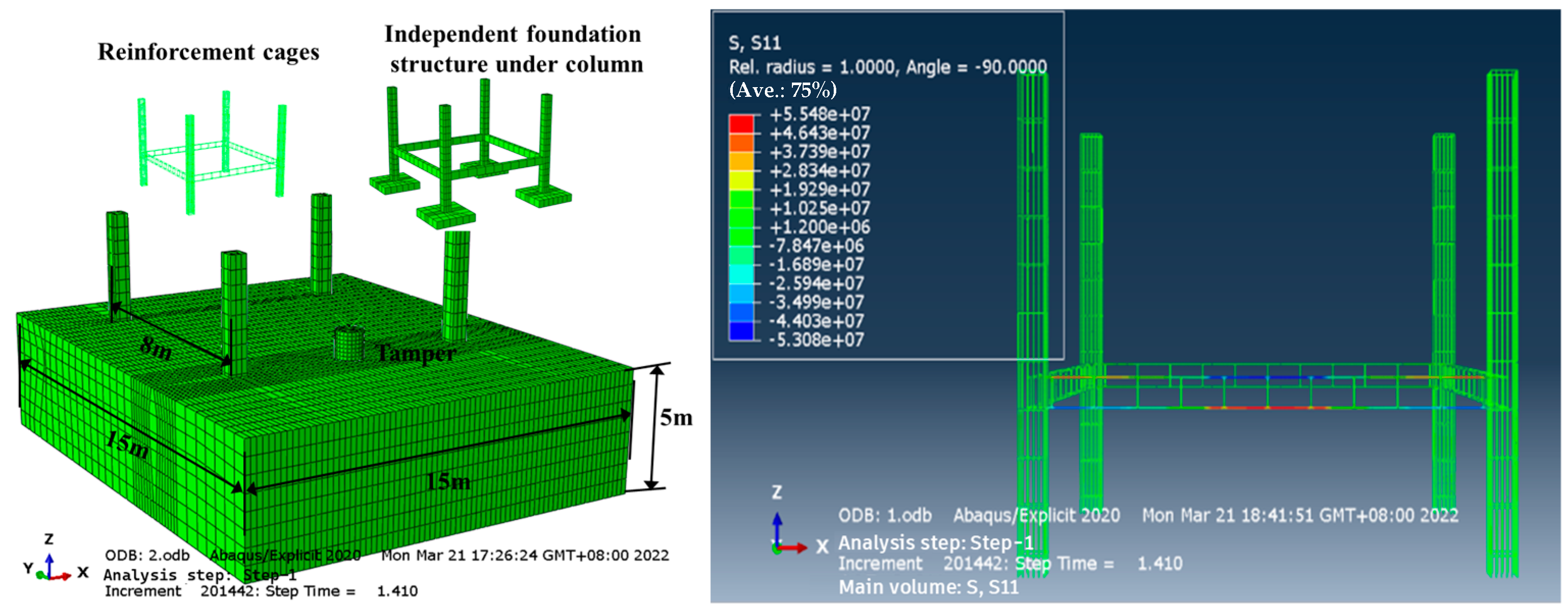
2.1. Numerical Models and Simulation Schemes

ABAQUS was used to create the computational model of the compactor, the independent foundation structure under the frame columns and the backfill, as shown in Figure 1. The compactor model is cylindrical with a height of 1 m, a diameter of 1 m and a mass of 6.2 t. The dimensions of the backfill model were 15 m and 5 m high, and the soil was divided into upper and lower layers according to the position of the foundation tie beams, with the lower layer being the backfill that had reached the compaction standard and the upper layer being the initially compacted fill. The independent foundation under the frame columns is a reinforced concrete structure, and the specific soil and structural parameters obtained based on field experiments are shown in Table 1. Each component is divided by eight-node hexahedral reduced integral (C3D8R) solid units, and the soil is modelled by the Drucker–Prager elastic–plastic model (the relevant soil parameters are shown in Table 1), with a unit size of 200 mm. The concrete is modelled by a solid unit with a unit size of 300 mm, which contains 219,891 units and 87,657 nodes (obtained through mesh density sensitivity analysis). The rebar model is then modelled using beam cells with a cell size of 100 mm. As determined by the boundary condition sensitivity analysis, displacement constraints were set at the bottom of the bearing and at the soil boundary to ensure stability; at the same time, the connection parts of the columns and tie beams were considered to be fixed, constraining all the degrees of freedom. In order to simulate the change rule of impact load transfer in the soil body, this paper adopts the triangular impact load model [19,20], whose action time is set to 0.1 s. In order to investigate the effects of different tamping energies and backfill thicknesses on the structural forces of free-standing foundations under columns during hydraulic ramming, these two factors are analysed in this study. Three types of tamping energy, 30 KJ, 36 KJ and 42 KJ, were selected according to the most common types of hydraulic tampers, and four different single backfill thicknesses, 0.5 m, 1.0 m, 1.5 m and 2.5 m, were selected.

2.2. Calculation Results and Analysis

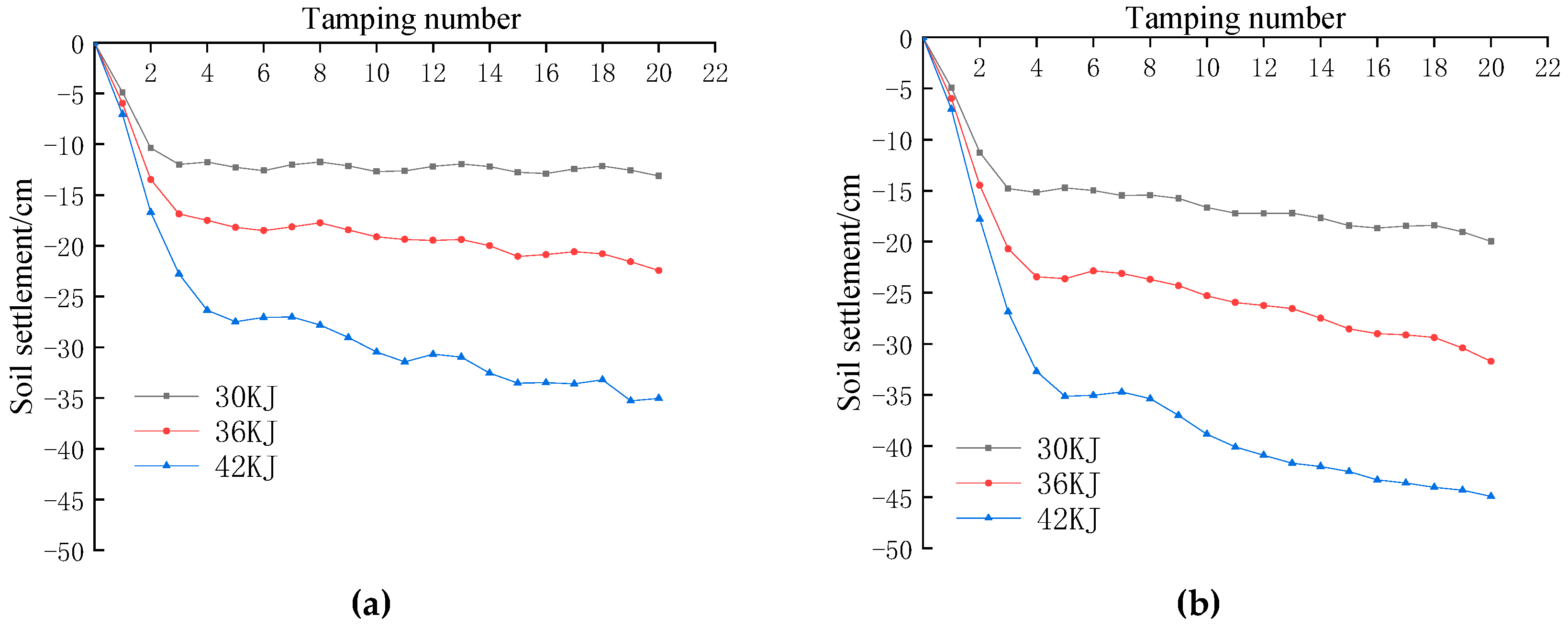
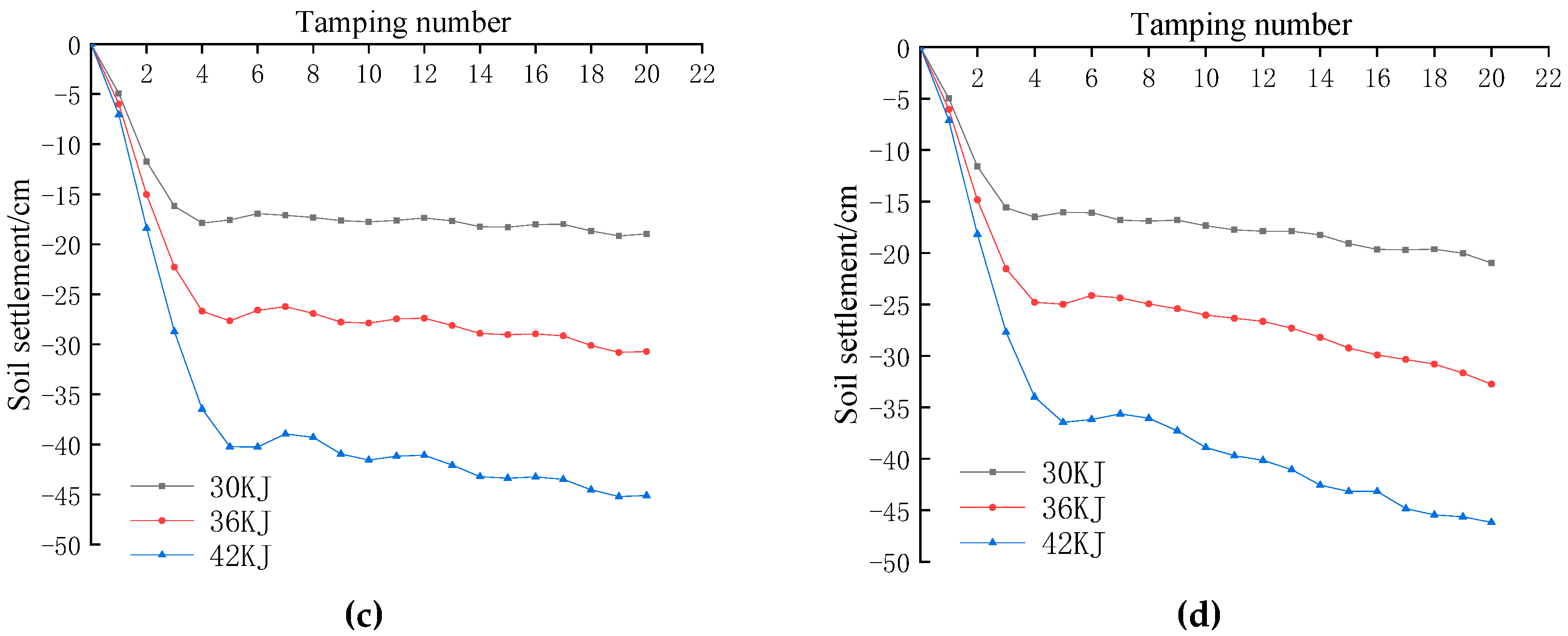
2.2.1. Analysis of the Optimal Number of Ramming Strokes

Soil settlement is determined by monitoring and analysing the displacement of the top of the soil in the vertical direction after being subjected to ramming. The settlement is monitored as the vertical displacement of the centre point of the FE grid subjected to the impact load. As shown in Figure 2, the variation curves of the cumulative soil settlement with the number of ramming strokes were obtained according to the numerical calculation results for different ramming energies and backfill thicknesses. From the figure, it can be clearly seen that the cumulative settlement of the soil body under different backfill thicknesses with the increase in the number of ramming shows a basically consistent pattern of change, i.e., the greater the ramming energy, the greater the cumulative settlement of the soil body. And when the number of ramming reaches 3~4 times, the cumulative settlement of the soil body basically tends to stabilise. According to the “Technical Code for Ground Treatment of Buildings (JGJ79-2012)” for a single tamping settlement less than 50 mm stop tamping provisions [21], from this research, it can be concluded that the number of tamping is equal to four can be used as the optimum number of tamping under the three types of tamping energy. The soil settlement of the fourth tamping under different working conditions is shown in Table 2.

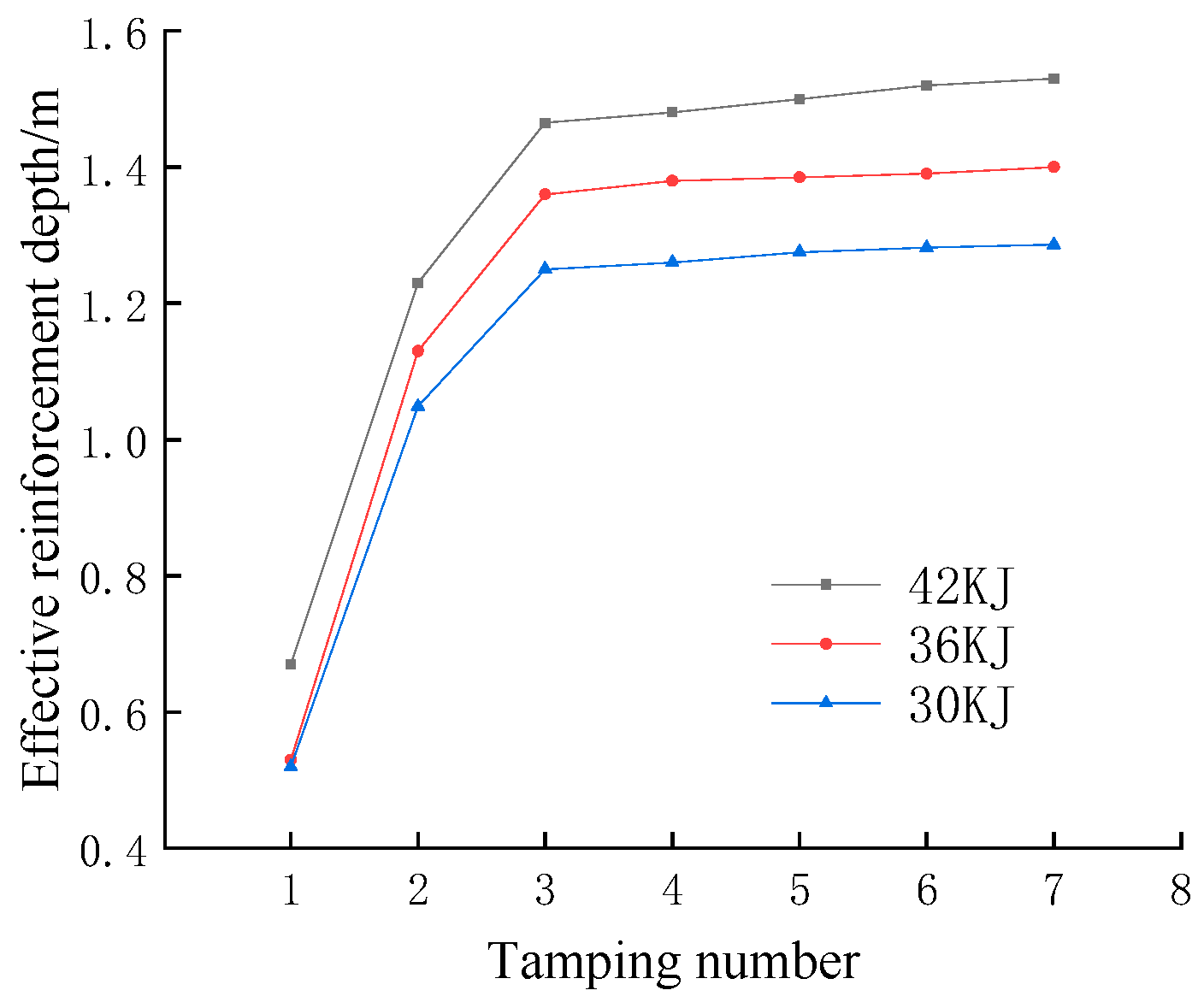
2.2.2. Analysis of Effective Reinforcement Depth

The hydraulic tamping method is an advanced foundation treatment technology that precisely transfers high-intensity impact energy to the foundation soil by means of a special tamping foot structure whose unique high-frequency tamping pattern significantly outperforms traditional tamping methods. There are a number of factors that need to be taken into account when assessing the depth of compaction using this method. These factors include not only the technical operating parameters, such as the thickness of the backfill, the lift height, the load factor of the hydraulic system, the weight of the compactor and the compactor foot and the contact area between the compactor foot and the soil, but also the physical properties of the soil itself, such as stiffness and the viscous damping coefficient. Given the complexity and interaction of the above factors, the traditional Menard’s formula cannot simply be applied to calculate the effective depth of foundation reinforcement for hydraulic ramming. On the contrary, it is necessary to take into account several factors, such as the load coefficient of the hydraulic system and the specific type of soil and its physical properties, as well as the effective area of the ramming plate. In order to predict and calculate the depth of foundation reinforcement more accurately, this paper adopts the modified Menard formula after thorough research and practical verification. This modification takes into account not only the loading coefficient of the hydraulic system and the specific type of soil and its physical properties but also incorporates important factors such as the effective area of the ramming plate and the thickness of the backfill. With this amended version, the aim is to provide a more scientific and accurate guide to the practical application of the hydraulic tamping method, thus ensuring the stability and safety of foundations. The modified Menard’s formula is as follows:
h = k μ G H h 0 3 d 1 d 2 2
where h is the effective reinforcement depth of the soil; h0 is the thickness of the backfill; k is the depth correction factor of the soil; μ is the loading factor of the hydraulic tamping system; G is the weight of the compactor; H is the drop distance; d1 is the diameter of the standard ramming plate for tamping machines; d2 is the diameter of the customised ramming plate.
According to previous related studies [22,23], this paper chooses to regard the depth of soil body with vertical displacement less than 0.015 m after a single tamping as the effective reinforcement depth. The variation curve of the effective reinforcement depth with the number of rammings for different ramming energies under 2.5 m backfill thickness was obtained by calculation (using Expression (1)), as shown in Figure 3. It is clear from the graph that the greater the tamping energy, the greater the effective depth of reinforcement. The effective depth of reinforcement increases with the number of ramming strokes; however, the increase gradually decreases. After the third ramming, the effective depth of reinforcement hardly changes at different ramming energies, which is close to the number of ramming strokes at which the cumulative settlement of the soil reaches stabilisation. The effective depth of soil reinforcement for the two working conditions of 1.5 m and 2.5 m backfill thickness was obtained by calculation (using Expression (1)), as shown in Table 2. As can be seen from Table 3, the thicker the backfill in the upper part of the tie beams, the deeper the effective reinforcement depth of the soil body at the same ramming energy, indicating that the lower anchor does have an effect on the effective reinforcement depth, but the effect is relatively small. Therefore, the effective reinforcement depth of the fourth ramming at 2.5 m backfill thickness can be used as a criterion for ramming. At the same time, the reinforcement depth calculated by the modified formula is basically close to the effective reinforcement depth, demonstrating the applicability of the modified Menard formula.

2.2.3. Structural Stress Analysis
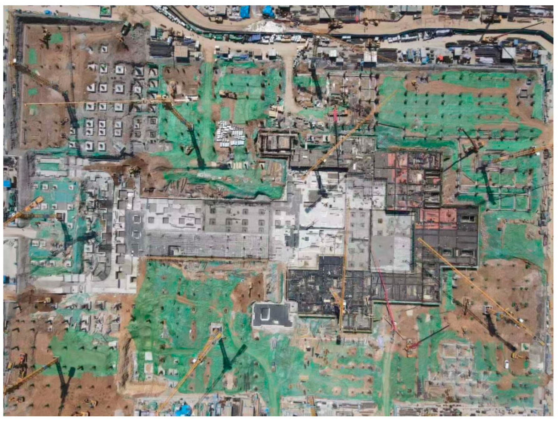
Figure 4 shows the variation of reinforcement stress with the number of ramming blows for different working conditions. It can be clearly seen that the change rule of the stress curve of the central reinforcement of the tie beams under different working conditions is basically the same, which is shown as follows: first, it increases to the maximum value, then it gradually decreases, and finally it shows the trend of up and down fluctuation. In addition, the greater the tamping energy, the greater the force on the reinforcement for the same backfill thickness. When the fourth tamping cycle is completed, the reinforcing force reaches its maximum value, and the reinforcing stress fluctuates up and down during the subsequent tamping cycles. Through the analysis, it can be learnt that the compression deformation of the soil body is the main factor leading to the change of the reinforcement force; when the soil body deformation is stable, the reinforcement force reaches the maximum value. Rebounding of the soil occurs during subsequent ramming; due to the cyclic loading, the reinforcement stresses show a pattern of up and down fluctuations. Under the same tamping energy condition, the reinforcement reaches the maximum value of the force in the condition of 0.5 m backfill thickness, followed by 1.0 m and the minimum in the case of 2.5 m, and the overall trend of the structural force increases with the decrease in backfill thickness being shown. Analyses based on the effective reinforcement depth of ramming revealed that the tie beams were located within the effective reinforcement depth of ramming for both the 0.5 m and 1.0 m backfill thicknesses, resulting in significantly higher forces on the tie beams than the remaining two cases. Therefore, when designing the structure, the thickness of the backfill, the magnitude of the tamping energy and the effective reinforcement depth of the tamping must be reasonably considered on the premise of ensuring the safety and stability of the structure in order to achieve an adequate tamping of the backfill.

3. Project Cases

3.1. Project Overview

In order to verify the accuracy of numerical calculations and investigate the force of independent foundation under columns in the whole construction process, this paper relies on a foundation project in Jinan to carry out on-site tests. The independent foundation under a frame column design scheme was adopted for this project, and its engineering location is shown in Figure 5. Due to the depth requirements of the foundations, tie beams were installed between the columns to increase the stability of the overall structure. The foundation elevation range is −9~0 m, and a tie beam structure is designed at −6 m, −3 m and 0 m within this range. To ensure the stability and safety of the structure, the atrium and the surrounding area were backfilled with plain fill. In terms of material selection, the columns and tie beams are made of C35 grade concrete structure, and φ25 mm HRB400 type reinforcing bars are used to enhance their load bearing capacity and seismic performance. For the construction of the independent foundation under the frame columns, a layered backfill and layered tamping method was used to ensure that each layer of backfill could be adequately compacted and stabilised. According to the results of numerical calculations, the thickness of the individual fills is controlled within 1.5 m to ensure the uniformity and compactness of the backfill.
The tamping operation consists of two main steps: initial compaction and spot tamping. Firstly, the initial compaction of the backfill is carried out using a compactor to ensure that the soil is maintained in a suitable state of moisture in order to eliminate voids and loose parts in the soil. This was followed by spot tamping using a 42 KJ hydraulic press, with each spot being tamped four times to ensure a tight bond between the soil particles. After the point tamping is completed, the backfill is again carried out with plain soil, and final compaction is carried out with a compactor to the design elevation. Then, the soil is filled again, and the above operation is repeated. Throughout the process, no additional water is added, and the natural moisture content of the soil is maintained. At the same time, the backfilling process needs to be carried out layer by layer in accordance with the design elevation until the desired filling height is reached.

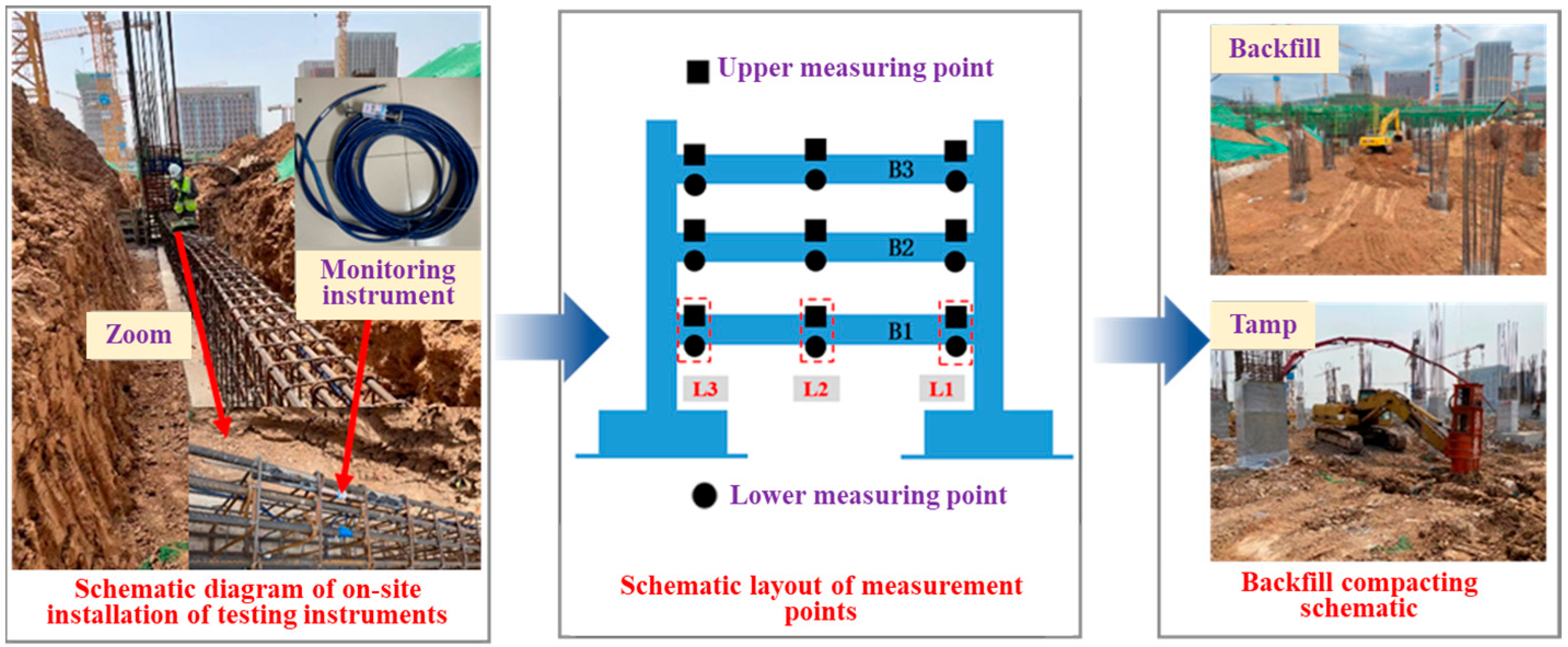
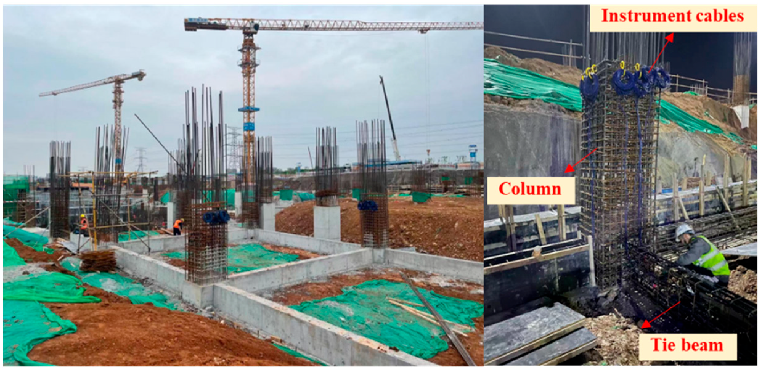
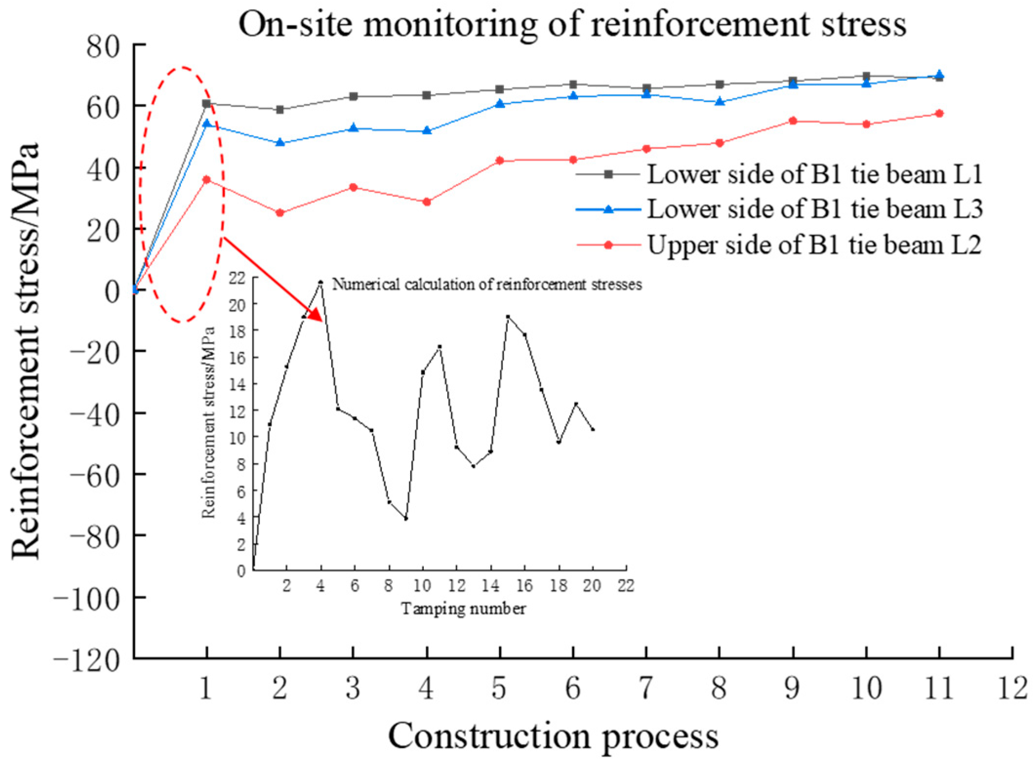
3.2. On-Site Monitoring

Given the vulnerability of freestanding foundation tie beams to ramming and construction impacts, the extensive monitoring of reinforcement stresses and concrete strains in the tie beams is required. The on-site construction process is shown in Figure 6. The selected monitoring unit includes three layers of tie beams, B1, B2 and B3, the tie beam measuring points are numbered from L1 to L3 (from the right end to the left end), and the measuring points are divided into the top side and the bottom side. Two reinforcement gauges and one concrete strain gauge were installed at each measurement point. In order to ensure the concerted deformation of the reinforcement gauge and the main bar, it is necessary to cut the main bar to a certain length when welding and then connect the connecting rod of the reinforcement gauge with the main bar by butt full welding; the concrete strain gauge is fixed on the main bar on the side of the welded reinforcement gauge. The foundation reinforcement field installation is shown in Figure 7.

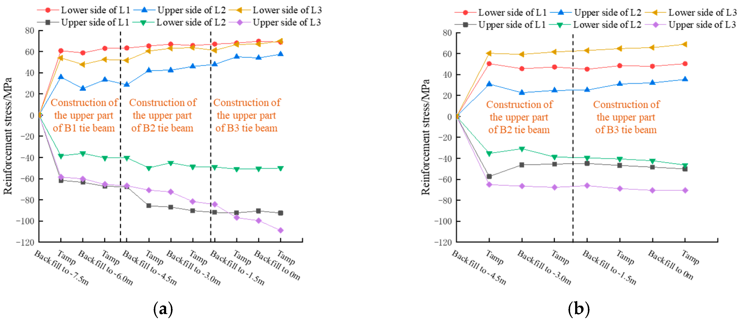
3.3. Analysis of Monitoring Data

In this study, the reinforcement stresses were analysed for tie beams B1 and B2 as shown in Figure 8. In order to reduce the error, the reinforcement stresses in the upper part of the tie beams after the first filling were set to an initial value of 0, and the reinforcement was specified to be positively compressed. From Figure 8, it can be seen that the upper side of the reinforcement stress at L1 and L3 measuring points is tensile and the lower side of the reinforcement stress is compressive. The stresses in the upper side of the reinforcement at L2 are compressive, and the stresses in the lower side of the reinforcement are tensile, which agrees with the numerical calculations. The tie beam reinforcement stress showed an increasing, fluctuating and smooth trend throughout the construction process, and the value of the reinforcement stress was in the range of −90~30 MPa, reaching 18.5~55.5% of the warning value (given in Table 3). A sudden increase in the reinforcement stress of the tie beam occurs after each ramming. For example, in the case of the B1 beam, the first tamping (1.5 m backfill thickness) showed the largest increase in reinforcement stress with an increment of about 35–60 MPa, reaching 21.6–37.1% of the warning value (given in Table 3). The second tamping (backfill thickness 3.0 m) showed a slight increase in reinforcement stress with an increment of about 2 to 8 MPa, indicating that the tamping of the backfill in the upper part of the B2 beam had an effect on the stresses in the B1 beam. It was analysed that the increase in stress in the B1 beam after the second tamping was not directly caused by the tamping but was related to the resulting synergistic stresses in the B2 beam.
The reduction in the reinforcement stresses at the end of the compaction of the backfill in the upper part of the B1 and B2 beams can be attributed to the fact that the backfill in the upper part of the beams is less and the compacted soil produces a rebound, which leads to a reduction in the stresses in the reinforcement. Comparing the rebar stresses in the same working condition under both field monitoring and numerical calculation, as shown in Figure 9, it can be seen that before and after ramming, the rebar stresses under both field monitoring and numerical calculation show the trend of increasing and then decreasing.
According to the code, there is no relevant specification that explicitly specifies the allowable stress range of the foundation reinforcement, so the provisions of similar articles should be referred to. Referring to the “Code for Design of Concrete Structures of Railway Bridges and Culverts (TB10092-2017)” [24], considering the role of the main force and additional force, the permissible stress of steel reinforcement is 270 MPa, which is the control value. The “General Code for Foundation Engineering of Building and Municipal Projects (GB 55003-2021)” [25] requires that the monitoring and warning value of columns in foundation pits and supporting structures should be 60 to 70 per cent of the design value of the constructed load-bearing capacity. According to the research and relevant norms, the calculation method is shown in Equation (2), and the control and warning values are detailed in Table 4. In conjunction with the above analysis, it is considered that the numerical modelling and field test results of the project satisfy its safety criteria.
σ = σ 60 %
where σ is the reinforcement stress warning value, and [σ] is the reinforcing steel stress tolerance value.

4. Conclusions

Based on specific engineering cases, this study uses ABAQUS software to construct corresponding numerical calculation models in order to investigate the effects of tamping energy, the number of tamping strokes and backfill thickness on the force of tie beams, and to apply the results of the study to the tamping construction. By comparing and analysing the numerical simulation results and the field monitoring data, the following conclusions were drawn:
  • Hydraulic tamping has an effect on tie beams when used to tamp the upper backfills of independent foundations under columns. By properly controlling the tamping energy, the number of tamps and the thickness of the fill, it is possible to ensure that the structure is in a safe condition. Similarly, the hydraulic compactor is also applicable to the treatment of independent foundations under columns.
  • In the case of tamping energy of 30 KJ, 36 KJ and 42 KJ, the recommended thickness of a single backfill is the effective reinforcement depth of tamping (1.26 m, 1.38 m and 1.48 m); for hydraulic tamping of 30 KJ and 36 KJ, the optimum number of tamping is three times, while for hydraulic tamping of 42 KJ, the optimum number of tamping is four times. In addition, the depth of reinforcement calculated according to the modified formula is in general agreement with the simulation results, providing a supplement to the relevant safety standards.
  • The tamping action of the compactor has a significant effect on the structural force within the effective reinforcement area, and the structural force is negatively correlated with the backfill thickness. At the same time, the engineering numerical simulation and on-site test results meet its safety standards; at 42 KJ compactor energy and 1.5 m single filling thickness, the tie beam reinforcement stress reaches the specification of the warning value of 18.5~55.5%.

Author Contributions

S.B., conceptualization and writing—original draft; L.C., investigation and software; H.Z., writing—review and editing; Z.Q., validation, methodology and formal analysis. All authors have read and agreed to the published version of the manuscript.

Funding

Financial support from the Key Laboratory of Geological Safety of Coastal Urban Underground Space, Ministry of Natural Resources (BHKF2022Y03).

Data Availability Statement

All data generated or analysed in this study are included in the published article.

Conflicts of Interest

Author Lishan Chen and Hailin Zhang are employed by the China Construction Eighth Bureau First Company. The remaining authors declare that the research was conducted in the absence of any commercial or financial relationships that could be construed as a potential conflict of interest.

References

  1. Zhang, W.X.; Liu, R.; Xie, H.T.; Yi, W.J. Experimental research on seismic behavior of reinforced concrete frame substructure considering soil-structure interaction. J. Build. Struct. 2021, 42, 72–81. [Google Scholar]
  2. Zhang, M.; Zhang, S.H.; Zhong, Z.L.; Hou, B.W.; Du, X.L. Robust geotechnical design of spread foundations. Rock Soil Mech. 2019, 40, 4506–4514. [Google Scholar]
  3. Zhang, J. Study on design method of single-footing with water-proof slab under column. Build. Struct. 2018, 48, 775–778. [Google Scholar]
  4. Haido, J.H. Prediction of the shear strength of RC beam-column joints using new ANN formulations. Structures 2022, 38, 1191–1209. [Google Scholar] [CrossRef]
  5. Xiong, W.; Qi, C.J.; Wu, X.L.; Li, H.T. Case study on treatment of large thickness miscellaneous fill soil foundation. J. Ground Improv. 2021, 43, 165–169. [Google Scholar]
  6. Zhu, J.J.; Zhang, H.M. Foundation treatment and pile foundation design for large-area filling. Build. Struct. 2017, 47, 454–457. [Google Scholar]
  7. Wang, J.; Zhang, Y.M.; Wang, K.; Li, L.P.; Cheng, S.; Sun, S.Q. Development of similar materials with different tension-compression ratios and evaluation of TBM excavation. Bull. Eng. Geol. Environ. 2024, 83, 190. [Google Scholar] [CrossRef]
  8. Gu, Q.; Lee, F.H. Ground response to dynamic compaction of dry sand. Geotechnique 2002, 52, 481–493. [Google Scholar] [CrossRef]
  9. Ji, M.; Zhang, Z.P.; Chen, C.C.; Zhou, Z.J. Research on Model Test of Hydraulic Compaction Method for Strengthening Subgrade on Abutment Subgrade. Highway 2020, 65, 1–9. [Google Scholar]
  10. Miao, X.Y.; Liu, H.Y.; Qu, Y.H.; Yang, H.; Li, K.C. Research on Application of Hydraulic Compaction Process on the Backfill of the Culvert. Highway 2017, 62, 30–35. [Google Scholar]
  11. Liu, J.Q.; Si, G.M.; Zhang, M.Q.; Shao, X.T.; Zhang, Q.L. Safety Evaluation of Culvert Structure in Construction Process of Lightweight Tamper. Road Mach. Constr. Mech. 2017, 34, 118–121. [Google Scholar]
  12. Hu, J.Y.; Xu, T.Y.; Yan, R.P.; Han, D.D.; Zhou, Z.J. Quality control method of hydraulic dynamic compaction reinforcing loess subgrade. J. Chang’an Univ. S.-Cent. 2020, 40, 15–26. [Google Scholar]
  13. Han, D.D.; Zhou, Z.J.; Lei, J.T.; Lin, M.G.; Zhan, H.C. Field experimental study for layered compactness of subgrade based on dimensional analysis. Geomech. Eng. 2022, 29, 583–598. [Google Scholar]
  14. Feng, X.H.; Wan, Z. Field test and numerical simulation study on treatment of expressway retailing backwall by hydraulic compaction. J. Railw. Sci. Eng. 2013, 10, 49–54. [Google Scholar]
  15. Zhang, Y.Z.; Yin, K.; Huang, J.H.; Liu, Y.S.; Li, C.C. Study on Shearing Resistance Design of Single Column Spread Footing on Rock Foundation. Chin. J. Undergr. Space Eng. 2019, 15, 1511–1518+1540. [Google Scholar]
  16. Li, X.C.; Yin, K.; Huang, J.H. Bending-expansion tensile failure of single-column footing on rock foundation. China Sci. Pap. 2017, 12, 1520–1525+1542. [Google Scholar]
  17. Zhou, S.; Chen, L.S.; Zhang, H.L.; Wang, J.; Zhang, P.Y.; Wu, G.; Zhang, Z.W.; Zhang, F. Study on the influence of hydraulic compaction of backfill on the stress of independent foundation structure under column. Build. Struct. 2023, 53, 2539–2544. [Google Scholar]
  18. Zhang, Z.K.; Chen, C.X.; Hou, Z.C.; Liang, Q.K.; Ou, Y.S. Rapid hydraulic compaction technology and determination method of its construction parameters. J. Ground. Improv. 2023, 5, 48–53. [Google Scholar]
  19. Li, B.P. Numerical analysis on pore pressure of clay under shock load. Combust. Explos. Shock. Waves 2005, 3, 281–284. [Google Scholar]
  20. Mohammad, M.N.; Elif, A.; Zeynep, Y. Experimental and numerical analysis of impactor geometric shape effects on steel beams under impact loading. Structures 2020, 27, 1118–1138. [Google Scholar]
  21. JGJ 79-2012; Technical Code for Ground Treatment of Buildings. The Standardization Administration of the People’s Republic of China: Beijing, China, 2012.
  22. Zhao, Y.L.; Gong, Y.L.; Zhang, Z.Y. Influencing factors of effective reinforcement depth by dynamic compaction on deep replacement of sand soil foundation. J. Heilongjiang Univ. Sci. Technol. 2023, 33, 710–717. [Google Scholar]
  23. Xie, W.D.; Chen, J.Y.; He, H.Y. Effect of dynamic compaction on hydraulic filled silty to fine sand with high fines content. Port Waters Eng. 2023, 9, 223–228. [Google Scholar]
  24. TB10092-2017; Code for Design of Concrete Structures of Railway Bridges and Culverts. National Railway Administration: Beijing, China, 2017.
  25. GB 55003-2021; General Code for Foundation Engineering of Building and Municipal Projects. Ministry of Housing and Urban-Rural Development: Beijing, China, 2021.
  26. GB 50497-2019; Technical Standard for Monitoring of Building Excavation Engineering. Ministry of Housing and Urban-Rural Development: Beijing, China, 2019.
  27. GB/T 1499.2-2018; Steel for the Reinforcement of Concrete—Part 2: Hot Rolled Ribbed Bars. National Standards of the People’s Republic of China: Beijing, China, 2018.
Figure 1. Finite element model.
Buildings 14 03331 g001
Figure 2. The cumulative settlement of soil under different working conditions: (a) 0.5 m backfill thickness; (b) 1.0 m backfill thickness; (c) 1.5 m backfill thickness; (d) 2.5 m backfill thickness.
Buildings 14 03331 g002aBuildings 14 03331 g002b
Figure 3. Effective depth of reinforcement with different ramming energies for backfill thickness of 2.5 m.
Buildings 14 03331 g003
Figure 4. Stress curve of reinforcement under different working conditions: (a) 30 KJ tamping energy; (b) 36 KJ tamping energy; (c) 42 KJ tamping energy.
Buildings 14 03331 g004
Figure 5. Site plan of an independent foundation project under a frame column.
Buildings 14 03331 g005
Figure 6. Site construction flow chart.
Buildings 14 03331 g006
Figure 7. Foundation treatment site plan.
Buildings 14 03331 g007
Figure 8. Stress time history curve of tie beam reinforcement: (a) B1 tie beam reinforcement stress; (b) B2 tie beam reinforcement stress.
Buildings 14 03331 g008
Figure 9. Field monitoring and numerical calculation of rebar.
Buildings 14 03331 g009
Table 1. Model calculation parameters.
Structural CategoryDensities/(g/cm3)Modulus of Elasticity/MPaPoisson’s RatioFriction Angle/°Cohesion/KPa
Upper soil1.2602.50.3824.8023.78
Underlying soil1.9605.00.3524.8023.78
Concrete structure2.5003.25 × 1040.20
Reinforcing cage7.85020.6 × 1060.35
Table 2. Settlement of the struck soil for the fourth ramming under different working conditions.
Thickness of Backfill at Top of Tie Beams/m0.51.01.52.5
Tamping energy/KJ303642303642303642303642
Soil settlement/cm11.717.526.315.123.432.717.826.636.416.524.733.9
Table 3. Effective reinforcement depth of the fourth ramming under different working conditions.
Thickness of Backfill at Top of Tie Beams/m1.52.5
Tamping energy/KJ303642303642
Effective reinforcement depth/m1.201.341.451.261.381.48
Calculation of reinforcement depth/m1.241.361.471.351.481.60
Table 4. Table of control and warning values.
Monitoring ProjectControl ValueWarning ValueGauge
Reinforcement stress270 MPa162 MPaGeneral Code for Foundation Engineering of Building and Municipal Projects (GB 55003-2021) [25]
Technical Standard for Monitoring of Building Excavation Engineering (GB 50497-2019) [26]
Code for Design of Concrete Structures of Railway Bridges and Culverts (TB10092-2017) [24]
Steel for the Reinforcement of Concrete—Part 2: Hot Rolled Ribbed Bars (GB/T 1499.2-2018) [27]
Disclaimer/Publisher’s Note: The statements, opinions and data contained in all publications are solely those of the individual author(s) and contributor(s) and not of MDPI and/or the editor(s). MDPI and/or the editor(s) disclaim responsibility for any injury to people or property resulting from any ideas, methods, instructions or products referred to in the content.

