Article

Structural Design and Technology of Pocket Foundations for Long Precast Concrete Columns in Seismic Areas

by
Horia Constantinescu
and
Traian-Nicu Toader
*
Department of Structures, Faculty of Civil Engineering, Technical University of Cluj-Napoca, Str. Constantin Daicoviciu 15, 400020 Cluj-Napoca, Romania
*
Author to whom correspondence should be addressed.
Buildings 2024, 14(11), 3466; https://doi.org/10.3390/buildings14113466
Submission received: 26 September 2024 / Revised: 11 October 2024 / Accepted: 22 October 2024 / Published: 30 October 2024
(This article belongs to the Section Building Structures)

Abstract

:
The connection between a prefabricated reinforced concrete column and a pocket foundation is a case treated from a general perspective in the European Standard named EN 1992-1-1 (EC2), and when the structural engineer deals with the dimensioning or verification of the connection, he must tackle several unknowns. The present work aims to fill in the missing information by presenting detailed calculation models based on the strut-and-tie method for four widely used pocket foundations: a pedestal pocket foundation with smooth, rough or keyed internal walls and a pad foundation with a pocket possessing keyed internal walls. In establishing the strut-and-tie models and writing the equation for the internal forces, we consider several standards (EC2, NBR 9062 and DIN 1045-1), good practices (from Austria, England, Germany and Romania) and numerous experimental and numerical investigations. Additionally, detailed design prescriptions applicable to seismic areas are given. This manuscript covers a wide range of design and technology aspects necessary for designing and building columns connected with pocket foundations, information for which is shown only in fragmented form or partially in other publications. Afterward, as a case study, a pocket foundation is designed in all four variations, with the structural design particularities, similitudes and differences being pointed out. Finally, to conclude, we mention the advantages and disadvantages of pocket foundations with respect to the type of internal wall surface used. Quantifiable data based on the case study undertaken are available.

1. Introduction

The precast concrete column–foundation joint must be able to transfer axial force, bending moment and shear force from the column to the foundation [1]. Isolated footings for prefabricated reinforced concrete columns can be designed as pocket foundations (Figure 1) or pad foundations (with anchor bolts, starter rebars, etc.) made of reinforced concrete [2].
Pocket foundations can have smooth, rough or keyed internal walls, and they can be designed with a socket (a pedestal pocket foundation) or a deep inner pocket (a pad foundation with a pocket), while the dimensions of the pocket interior must be sufficient to properly fill the space between the column and the foundation inner walls with fresh concrete [1,2,3,4]. For pocket foundations with keyed internal walls (Figure 1), if the geometry of the castellation fulfills the requirements given in [1,2,3], then the precast column–pocket foundation joint is considered to exhibit a structural response similar to a monolithic column–foundation. Moreover, for pocket foundations with smooth or rough internal walls, the transfer of the internal forces from the column to the foundation is considered to take place through normal pressure and friction [1,2,3]. When the column is subjected to tensile axial forces, only the use of pocket foundations with keyed internal walls is allowed [2] (par. II.6.2.2). The necessity of using keyed surfaces for columns in tension is motivated by the fact that under seismic loading relying only on friction (as in the case of smooth and rough surfaces) it is extremely risky, and the local failure of a structure due to a column being pulled out of the foundation is very likely to end up with the extended collapse of the building.
Reinforced concrete pad foundations without pockets can have simple, sloped or stepped footings [2]. The transfer of bending moments and tensile axial forces from the precast concrete column toward the foundation is carried out through anchor bolts or starter rebars, while the shear force is transferred through shear dowels [2,5,6,7,8].
Foundations can be made of monolithic reinforced concrete, partially monolithic concrete (monolithic and prefabricated collars) or fully prefabricated concrete [5,9]. Entirely prefabricated foundations are rare because of their size (they become oversized when their size in the horizontal plane exceeds 2.5 × 2.5 m) and due to the difficulties of placing them in a perfectly horizontal position with full contact between the entire bottom surface and the ground [9,10,11].
In earthquake-resistant structures where the seismic energy is dissipated through the formation of plastic hinges at the base of the columns, the column–foundation joints must be designed in such a way as to allow the yielding of the column’s longitudinal reinforcement without degradation and the reduction in the load-bearing capacity in the joint region [5,6,12].
Figure 1. The precast socket of a pocket foundation with keyed internal walls (left), the geometry of the castellation (center) considering the most restrictive indications stated in [1,2,3,13,14,15,16,17,18,19] and the base of the prefabricated concrete columns stored in a stack (right).
Buildings 14 03466 g001
The types of foundations for prefabricated concrete columns, in which the dimensioning of the column–foundation joint interfaces is considered, are as follows:
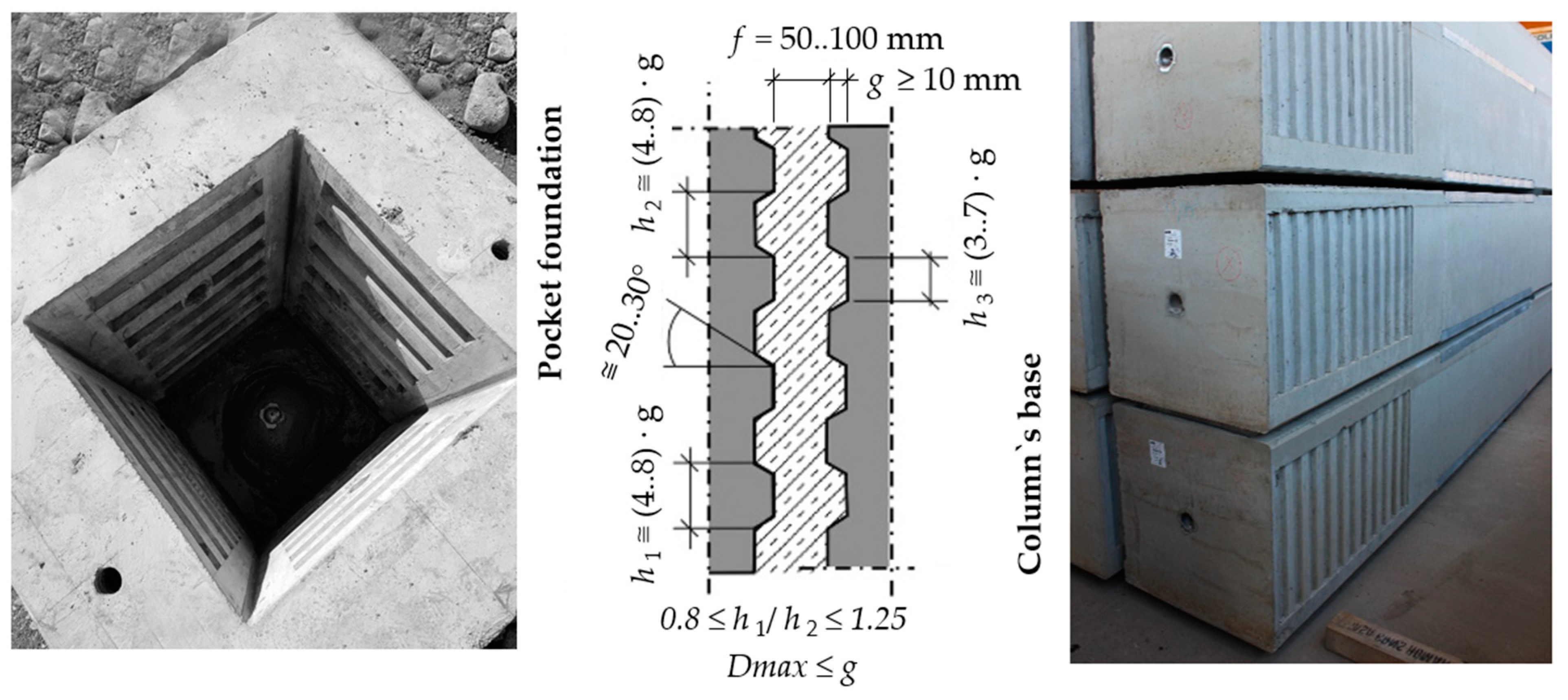
  • Pedestal pocket foundation with smooth internal walls;
  • Pedestal pocket foundation with rough internal walls;
  • Pedestal pocket foundation with keyed internal walls;
  • Pad foundation with pocket and keyed internal walls.
The criteria to be considered when choosing the prefabricated column–foundation connection are as follows [2,5,20,21,22]:
  • The level at which good soil is located (TBF) in relation to the natural land level (CTN) and the developed land level (CTA), and implicitly compared to the ±0.00 level of the future construction;
  • The nature of the soil and the execution technology used for the infrastructure;
  • The groundwater level (NAS);
  • The reaction forces transmitted by the superstructure and their magnitude;
  • The owner’s requirements;
  • Quality control in conjunction with building costs.
The precast concrete column–pocket foundation keyed connection (Figure 1) can be treated in design calculations as a monolithic joint between the concrete column and foundation [1,2]. For punching shear conditions, the design should assume a monolithic column-to-foundation connection, making it essential to verify the shear transfer between the column and the footing [1,2,23].
This work aims to provide clear, comprehensive and complete strut-and-tie models for each of the four types of pocket foundations, ensuring structurally sound and seismically resistant joints. It then defines the equations necessary for designing reinforcement within the pockets and standardizes notation across all pocket foundation types, incorporating structural and seismic provisions from the current design standards. The significance of this paper lies in offering detailed guidance for structural design and code compliance without resemblance to the available technical literature [1,2,3,5,6,7,9,11,24,25] and correlating with the experimental findings published in scientific journals [26,27,28,29,30,31,32,33].

2. Materials and Technology

The steps in designing the structural precast column–pocket foundation connection can be outlined as follows:
  • Choosing the materials used (concrete classes, types of reinforcement) and the type of foundation;
  • Choosing the technology for mounting the column in the pocket foundation;
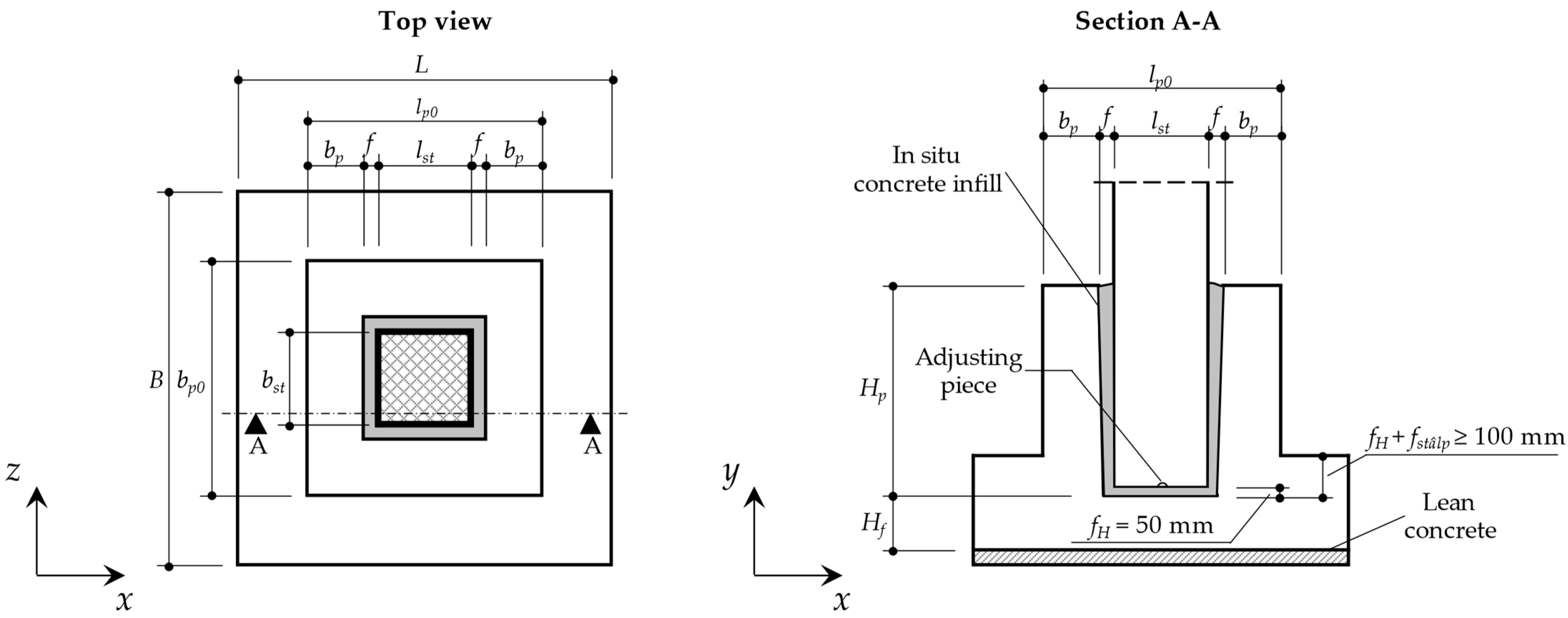
  • Pre-dimensioning of the pocket foundation (height of the pocket Hp, wall thickness bp, and concrete infill thickness f, fH and fstâlp);
  • Dimensioning of the pocket foundation (checking the concrete cross-section, calculating the amount of reinforcement necessary and reinforcement positioning in the concrete volume);
  • Dimensioning of the slab foundation (foundation footing);
  • Preparation of technical drawings;
  • The inclusion of the construction particularities in the “Technical specifications”.

2.1. Materials and Choosing the Type of Foundation

Concrete is characterized in both its fresh and hardened states by classification. According to the standards for concrete production and execution [1,15,34,35,36], the following 5 types of classes are used:
(a)
Compressive strength class: Denotes the characteristic value of the concrete compressive strength determined for a concrete cylinder, respectively, and the characteristic value of the compressive strength determined for a concrete cube, both expressed in MPa. Therefore, a concrete whose characteristic value for compressive strength is at least 30 MPa per cylinder, respectively, at least 37 MPa per cube, will be marked with C30/37 (Figure 2);
(b)
Environmental exposure class: This is correlated with the lifetime and maintenance of the structure (usually 50 years). Depending on the environmental conditions to which the structure is exposed (infrastructure, respectively, superstructure, as the case may be), the corresponding exposure classes will be identified. Reinforced concrete elements will be classified in one or more exposure classes, such as XC1..4 (risk of corrosion of steel by carbonation), XA1..3 (risk of a chemical attack on concrete), XD1..3 (risk of corrosion of steel due to chlorides), XS1..3 (risk of corrosion of steel due to chlorides in seawater), XF1..3 (risk of attack on concrete by freeze–thaw), etc. For example, a reinforced concrete foundation in a humid and rarely dry environment corresponds to exposure class XC2, and this implies the use of a minimum class of C25/30 concrete (Figure 2);
(c)
Class of chlorides: This is the maximum amount of chlorides contained in fresh concrete with reference to the mass of the cement in its composition. Both the amount of chlorides contained in the aggregates and the amount of chloride ions, Cl, in the fresh concrete mixture should be considered. For example, for steel-reinforced concrete, the maximum chloride content of the aggregates is 0.04%, and the maximum Cl content by mass of cement is 0.2% or 0.4%. As a result, reinforced concrete will be marked by Cl 0.20 or Cl 0.40, both classes being accepted;
(d)
Consistency class: This denotes the workability of fresh concrete. For example, fluid concrete is denoted by S4;
(e)
Density class: This indicates the density of unreinforced (plain) concrete in its dry state. Concrete with a density equal to 2.4 tons/m3 can be marked as D2.4.
Additionally, the thickness of the concrete cover for reinforcement is influenced by the structural class [1,15] (e.g., a building designed for a 50-year service life corresponds to structural class S4). The values of internal forces obtained from structural analyses used for sizing load-bearing elements are also impacted by the importance-exposure class [6,15] (ex., a current type of construction that corresponds to importance-exposure class III).
The concrete strength class is determined considering the following:
  • The maximum tension in the concrete for the considered structural member;
  • The ductility class of the structure (seismic design);
  • The exposure class.
In Romania, it is a widespread practice to produce prefabricated elements with concrete class C30/37 or higher [5].
Infill concrete. The connection between the precast column and pocket foundation is a wet joint, achieved by filling the space between them with concrete. Before positioning the column in the pocket and pouring the infill concrete, it is essential to clean and moisten the connection interfaces with water. The infill concrete strength class should be at least equal to that of the pocket foundation concrete [2]. The recommended maximum aggregate size is Dmax ≤ minimum (f/3, 16 mm) [14,15]. The infill concrete must have a fluid consistency (consistency class S4 or F5) and be non-shrink to prevent contraction during hardening.
Compliance with the provisions contained in the technical regulations regarding concrete strength classes in correlation with the exposure classes [1,2,34,35,36] leads to a reduction in the risk of premature degradation of reinforced concrete elements, or in other words, contributes to ensuring adequate durability of the superstructure and infrastructure of the buildings designed and constructed.
Reinforcement. The most commonly used reinforcement in the vertical members of the superstructure (columns and walls), as well as in foundations, is steel, with a strength class of B500 and a ductility class of B or C. This type of reinforcement is also considered an economical option. Other strength classes of reinforcing steel in use include B400, B420, B450 and B490, all with ductility categories B or C. In the past, hot-rolled steel was used, including OB37 (smooth rebar, equivalent to B235Cs), PC52 (periodic profile rebar, equivalent to B345Cs) and PC60 (periodic profile rebar, equivalent to B405Cs). Ductility class A reinforcing steel is only allowed for foundations and columns/walls [2,6] when these members are designed to remain in the elastic range (without cracking). The second generation of EC2 [3] specifies the use of reinforcing steel strength classes ranging from B400 to B700.
The technical regulations describing the types of reinforcing steel to be used are as follows: ST 009-2011, “Technical specification for steel products used as reinforcement/Specificație tehnică privind produse din oțel utilizate ca armături”; SR 438-1:2012, “Steel products for concrete reinforcement/Produse de oțel pentru armarea betonului/”, respectively; EN 10080:2005, “Steel for the reinforcement of concrete/Oțel pentru armarea betonului”.
For structures with columns subjected to small axial compressive stress, the pedestal pocket foundation with keyed, rough or smooth internal walls and shallow isolated footing (with a foundation depth of approx. −2.00 m underneath the finished floor) is often a convenient one. When the column is subjected to tensile axial force, it is necessary to use a pocket foundation with keyed internal walls and, possibly, with isolated footing on the piles. It is appropriate to use a pad foundation with pocket and keyed internal walls in the following cases: The column is subjected to compression with small or medium eccentricity, and the good soil is near the level of the finished floor; if the soil is a hard rock (e.g., marl) and its upper level is near the future finished floor; or if the groundwater level is near the level of the finished floor.

2.2. The Technology of Mounting the Column in the Pocket Foundation

The sequence of steps for mounting the prefabricated reinforced concrete column in the pocket foundation [5,20,36,37,38] can be summarized as follows:
(a)
Marking the axes of the foundation and positioning the centering device on the bottom of the pocket on a concrete layer that is approx. 50 mm thick (at least of the same strength class as the infill concrete);
(b)
Marking the station points of the mobile crane (by beating poles or painting the ground surfaces) and parking points for the trailer (when the installation is done directly with unloading from the transport equipment) in accordance with the technological project;
(c)
Transporting the columns in the vicinity of the final mounting position;
(d)
Cleaning the inner surfaces of the pocket and the outer surfaces at the base of the column;
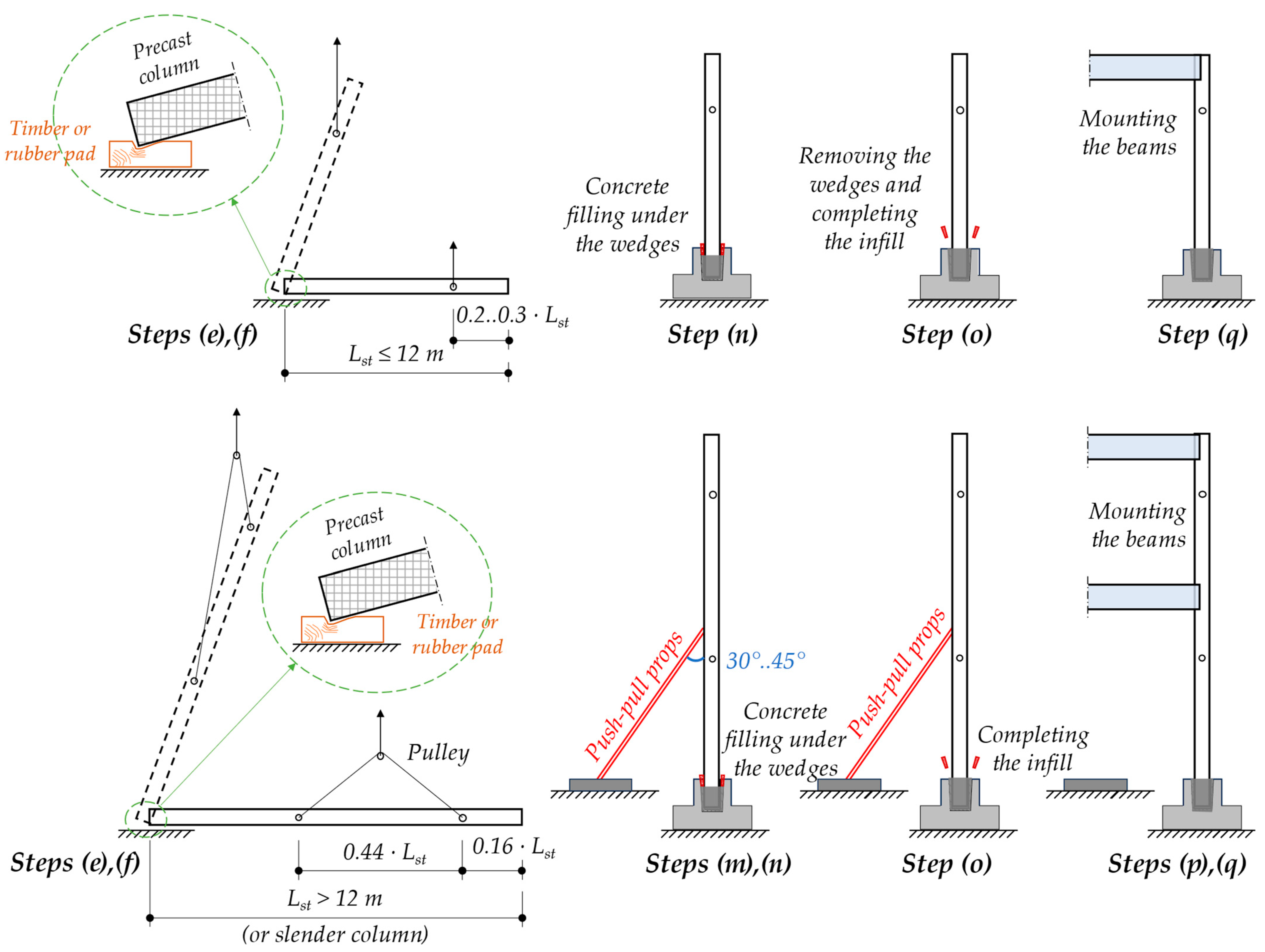
(e)
After positioning and centering the mobile crane, the handling device is fixed on its hook and mounting of the columns starts;
(f)
After placing the column horizontally on the ground, the column is lifted again to be brought to a vertical position (by crawling, turning or tipping);
(g)
Cleaning the column’s leaning areas and marking down the structural axes on the sides;
(h)
Fastening the guide ropes to the column;
(i)
Slow lowering of the column into the foundation and adjusting its position by workers with the help of ropes and two crowbars so that the axes marked on the column coincide with the position of the axes marked on the foundation;
(j)
Verifying the verticality of the precast column on the two orthogonal sides using a plumb line, bubble level (spirit level) or laser level, followed by the initial temporary fixation of the column at the foundation level by hammering special hardwood wedges (e.g., oak, beech, acacia, etc.) on each side (minimum 6 wedges in total, of which on two parallel faces there are at least 2 pieces) [20]. The geometry of a wedge is a quadrilateral prism type, with one of the faces chamfered under an angle of 10 sexagesimal degrees [20], with a length of about 300 mm and a width of about 100 mm (Figure 3). The geometry of the wedge is made in such a way that after hammering, it remains above the pocket foundation by approx. 120 mm. The use of wedges with too large angles, wedges made of soft wood (e.g., spruce, fir, pine, etc.) or overlapping wedges to compensate for their insufficient thickness may lead to the rotation of the columns in the foundation under the wind action or under an accidental action (e.g., the collision of heavy members with columns) and their collapse in the intermediate phases of construction execution (Figures S1–S9, Videos S1 and S2). In the mentioned figures and videos, one can see the domino effect following the rotation of a column in the pocket foundation caused by a gust of wind with a speed of up to 80 km/h. The dynamic action of wind can cause the expulsion of the wooden wedges as a result of the cyclical/balanced movement of the precast column. From a row of 11 precast reinforced concrete columns, the first column did not rotate in the pocket foundation, the second column rotated (the wooden wedges being crushed or expelled), and the deformed shape of the column was large enough to hit the third standing column (Figure S1). Following the impact, the third column rotated in the pocket foundation (by crushing the wooden wedges or by expelling them, Figure S2), hitting the fourth column. After the impact, the fourth rotated at the base and deformed and broke under its own weight. Now broken, in the fall, the fourth column hit the fifth column with amplification from the shock, and the remaining failures happened similarly, ending with a total of 8 prefabricated columns collapsing (Figures S3–S9). It can be noticed that the first fallen columns (the fourth and fifth) developed a single plastic joint each (the cross-section broke at the base), but the next 5 columns developed two plastic joints each (one at the base and one at the middle of the height as a result of the change in the static scheme: from a cantilevering beam to that of a beam hinged in the foundation and supported at the top). The causes of the failure could be one or more of the following: A high wind loading in the intermediate construction phase (the precast column–pocket foundation interspace was not completed); the fixing with wooden wedges was not correctly carried out (insufficient wedges, wedges with a chamfering of only about 20°…30°, the wooden wedges were short, the thickness of the wooden wedges was supplemented by using short ends of wooden slats or softwood was used); and the distance between the pocket foundation internal wall and the precast concrete column (thickness of the concrete infill layer) was excessively large—a situation in which after the expulsion of the wedges, the rotation of the column at the base was so great that its tip collided with the neighboring column;
(k)
Checking the verticality of the precast column using more precise equipment (with topometric devices), adjusting the position of the column by loosening/hammering the oak wedges;
(l)
For slender precast reinforced concrete columns, as well as for those whose length exceeds 12 m, it is recommended to use tilt props or scaffoldings for additional temporary fixing (Figure 4). The tilt props will be mounted in such a way that they can take compression forces (and tensile forces, if possible), their inclination should be at 30°…45° (the angle measured between the longitudinal axis of the prop and the column) and their arrangement must provide stability in two orthogonal directions in the horizontal plane. In the case of exceptionally long columns, scaffolding or other temporary constructions with a similar effect will be used for temporary support;
(m)
Additional topometric verification is required after mounting all columns in both horizontal directions (in-plane) and vertically (in elevation). At the end, the final hammering of the oak wedges is carried out, and if tilt props/scaffolding are used, they will be firmly fixed to the concrete blocks and to the columns;
(n)
The concrete surfaces that come into contact with the fresh infill concrete (the base of the column and inner surfaces of the pocket) are sprayed with water. The infill concrete is poured until it reaches the bottom level of the oak wedges. After pouring, the fresh infill concrete is vibrated with a concrete compactor;
(o)
The oak wedges are removed after the infill concrete has reached approx. 70% of the compressive strength (approx. 3 days) that the infill concrete has at 28 days. Sprinkling with water (watering) the hardened concrete surfaces that come into contact with the rest of the fresh concrete for filling the remaining column-pocket interspace;The tilt props/scaffolding are removed after the last part of the infill concrete is poured into the interspace and has reached approx. 70% of the compressive strength that the infill concrete has at 28 days;
(p)
Mounting the beams is carried out after the concrete filling in the column–pocket interspace is completed (Figure 4), has hardened and has reached the strength class mentioned in the project’s technical documentation (e.g., technical drawings, technical specifications, etc.) unless there are other specifications from the structural engineer.
Images documenting the construction of pedestal pocket foundations with precast sockets (Figures S10–S15) and monolithic sockets (Figures S16–S20) are added as Supplementary Materials to this article.

3. Pre-Dimensioning and Design Method

3.1. Pre-Dimensioning of Socket in Pedestal Pocket Foundation

Pocket’s wall thickness, bp. The minimum thickness specified in the standard [2] is 150 mm for sockets cast in plants and 200 mm for those cast on site, but not less than one-third of the short side of the column’s cross-section (Figure 5). However, Tillmann et al. [7,11,22] recommend a minimum thickness of 250 mm. An overview of the minimum wall thickness is presented in Table 1. Sometimes, sockets are made with variable wall thicknesses and with an inclination of about 3° to 5° [2,20].
The thickness of the concrete infill, f. It is recommended that the infill thickness is f = 50..75 mm at the base of the pocket and f = 85..120 mm at the top [2]. For pockets with vertical internal walls (0° inclination), a thickness of f = 75..120 mm is used. In the case of pockets containing two or more columns without intermediate walls, the concrete infill should have a minimum thickness of 50 mm between the neighboring columns to ensure the complete filling of the interspace [2].
The thickness of the concrete infill underneath the column, fH, and the embedding depth of the column’s base in the slab’s foundation, fstâlp. In current design practice [5] fH and fstâlp are 50 mm each (Figure 5). For large horizontal reaction forces, these values can be increased.
The thickness of the slab foundation, Hf, is sized after checking for punching (in the mounting and final phases) and considering Hf ≥ 250 mm.
The depth of the pocket, Hp, is determined based on the requirements for embedding the column in the pocket foundation and ensuring the anchorage length (lbd) of the column’s longitudinal reinforcement. Table 1 consolidates the pre-dimensioning equations for the pocket’s height, as specified in EC2 [1,3], which serves as a structural design standard in many European countries and other parts of the world. Additionally, pre-dimensioning provisions from design norms in countries with moderate to high seismicity, such as Romania [2,6,41] and Brazil [42], are included in Table 1.
Conclusions are to be drawn based on the study in Table 1. The most numerous and restrictive provisions concerning the pocket wall thickness are those outlined in NP 112-2014 [2] and NP 112-04* [41]. The maximum pocket height is determined by applying the pre-dimensioning mathematical expressions from Leonhardt and Mönnig (1975) [25]. Unlike the calculation models in the design codes [1,2,3,41,42], these expressions neglect the friction at the column–pocket foundation interfaces when transmitting reaction forces from the column base to the pocket foundation [43].
Several experimental investigations on the columns embedded in pocket foundations [44,45,46,47,48] have shown that neglecting this friction leads to an experimental load-bearing capacity of the pocket foundation that is three times greater than the capacity calculated using models that ignore friction [43]. Therefore, it is necessary to consider friction in the calculation model of the column–pocket foundation joint to achieve a more rational design [43].
In the case study conducted in Section 3, the mathematical expressions from [1,2,6] will be used, as they represent the most recent versions of the design standards in effect and are applicable for designing structures in seismic areas.

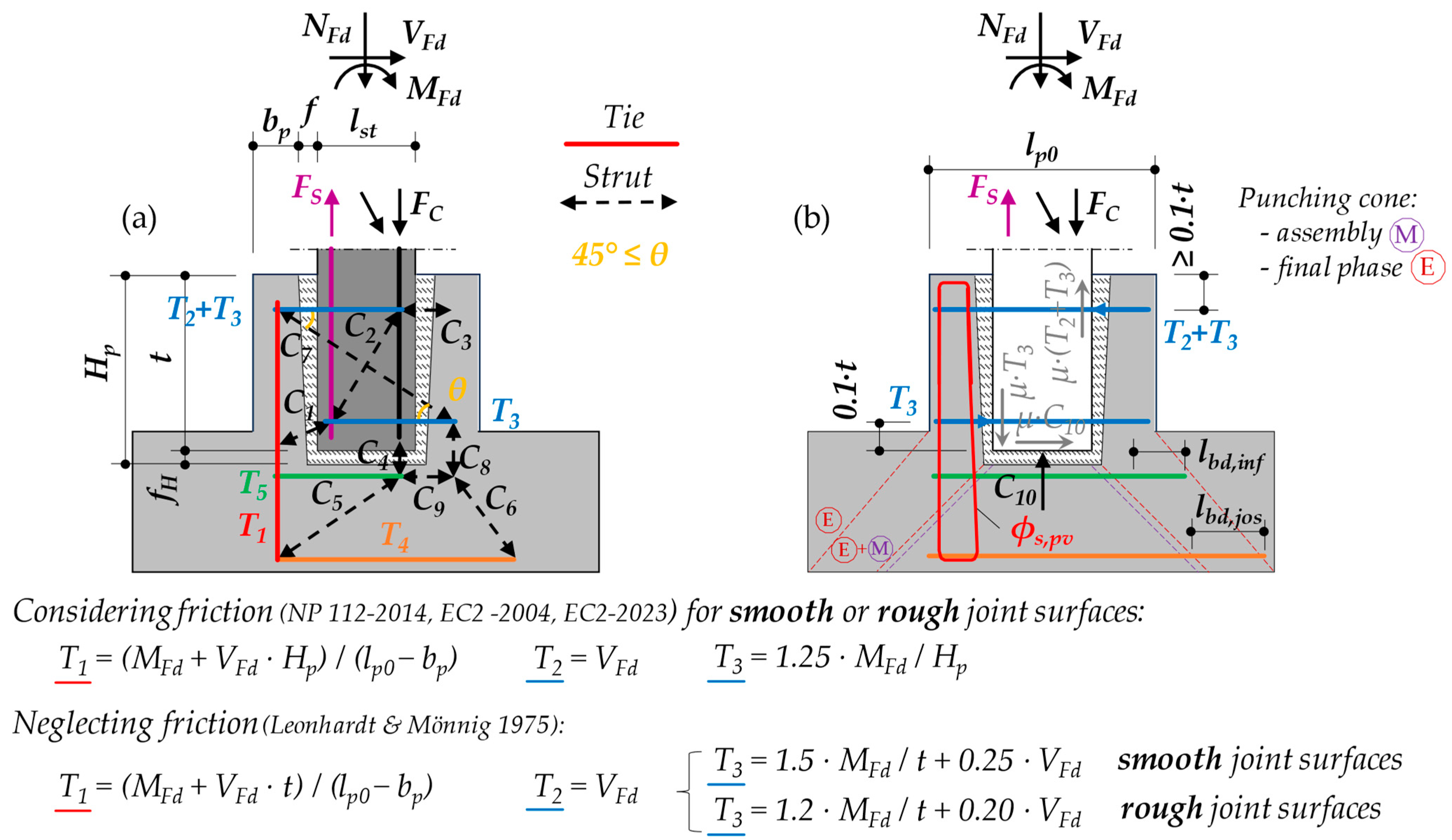
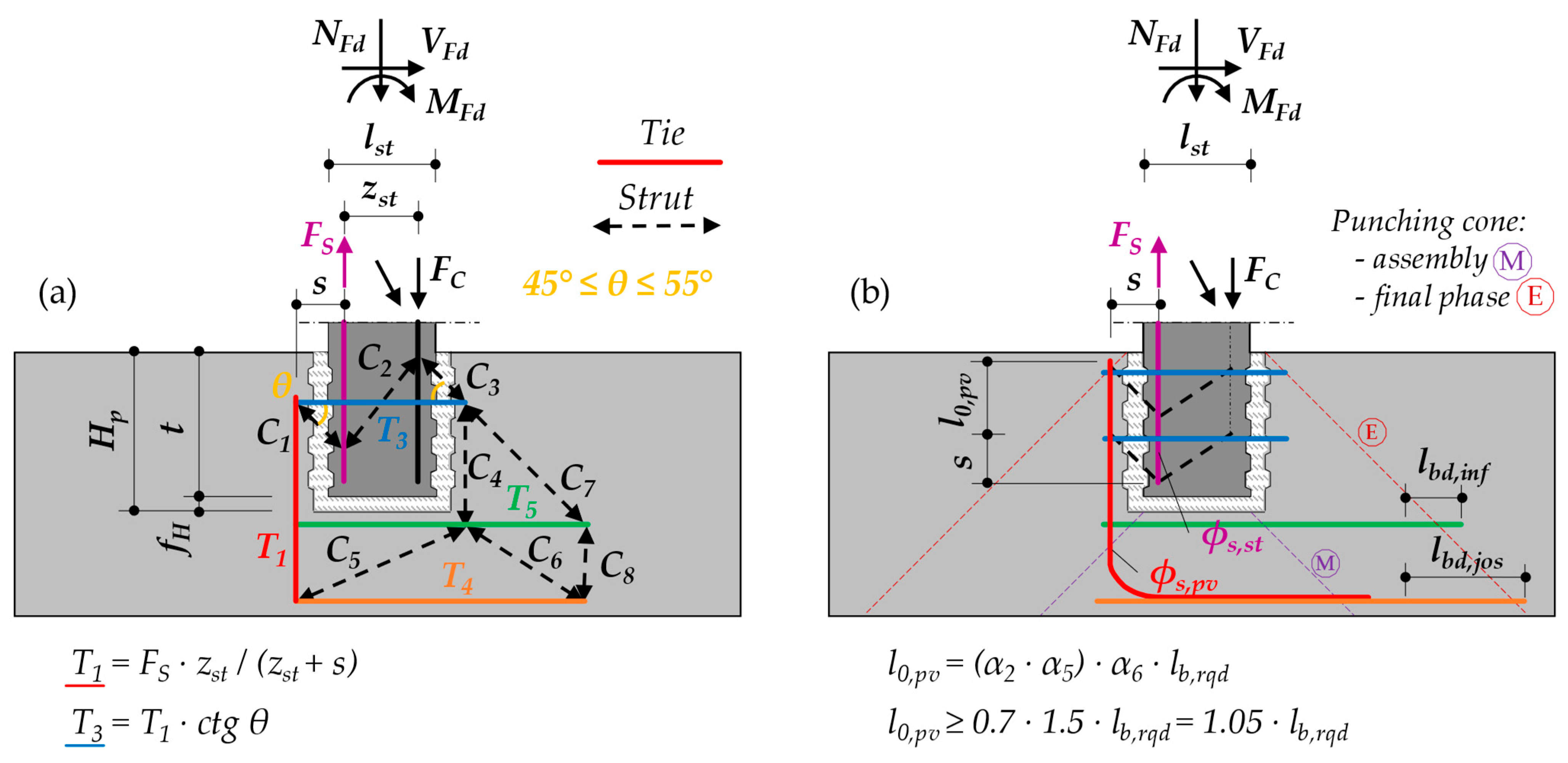
3.2. Sizing the Pocket Foundation Using Strut-And-Tie Models

In mathematical models for sizing pocket foundations, the column is treated as a solid rigid body throughout its entire embedding depth in the foundation. However, when using pocket foundations with thin walls (bp < lst/3) or when the shear force at the column’s base, VFd, is high (e.g., in the case of short columns, designs for accidental truck impact situations, etc.), it becomes important to check the pocket’s walls for out-of-plane bending, as it becomes relevant and can be decisive in the sizing of the pocket foundation.
Figure 6, Figure 7 and Figure 8 illustrate the mechanical model employing the struts and ties (also named the truss model) developed to determine the internal forces. For dimensioning the concrete cross-section and reinforcement, the specified equations can be utilized, or new equations can be derived either analytically or through numerical methods, keeping to the calculation assumptions specified in the design standards. Additionally, experiment-based design is an alternative approach in the designing of pocket foundations.
The design of pedestal pocket foundations with smooth or rough internal walls has been analyzed and experimentally validated in several studies [27,28,49,50,51], as well as the design of pedestal pocket foundations with keyed internal walls [28,52,53,54]. The values of the internal forces that can be obtained using the given equations at the bottom of Figure 6, Figure 7 and Figure 8 are conservative. For pedestal pocket foundations with smooth or rough internal walls, if μ·C10 ≥ T3, then horizontal reinforcement in the lower half is arranged according to the rules prescribed in [1,2,3].
The structural design of pad foundations with pocket and keyed internal walls should be conducted similarly to that of a monolithic foundation. It is important to note that the internal walls of the pocket are reinforced with vertical and horizontal rebars, with sizing performed based on the internal forces T1 and T3. The geometry of the castellation must adhere to the provisions outlined in Section 3.3.
The transfer of internal forces in the column’s cross-section at the top of the pocket occurs as follows: NFd is transmitted through the lateral keyed surface of the column embedded in the foundation; MFd is transferred via the pair of internal forces FS and FC, which determine the required reinforcement areas in the pocket’s wall (As,pv and As,ph); and VFd is considered to be transmitted directly into the block through compressive forces. If the foundation is sufficiently massive, no additional reinforcement is needed to resist the shear force at the base of the column or the bottom of the pocket.
The group of internal forces NFd, VFd and MFd cannot be directly extracted from the static calculations; instead, they must be analyzed to ensure that the bending moment for which the foundation is designed in the seismic combination is at least equal to or greater than the resisting bending moment (MRd) of the column at the embedding section (top of the pocket). Furthermore, the resisting shear force must be at least equal to the shear force associated with the occurrence of MRd. For each loading combination (fundamental and seismic) [55], groups of internal forces will be evaluated for both the maximum and minimum values of the axial force in the column. The calculation model and reinforcement arrangement are illustrated in Figure 8.
The provisions for anchoring the vertical reinforcement in the pocket foundation and the column, which apply to column–pocket foundations, are as follows [1,2,3,5,6,7,9,11,24,56]:
(a)
The vertical reinforcement placed in the pocket foundation shall be properly anchored at both ends. At the bottom end, the vertical rebars will be continued in the slab’s foundation until above the horizontal slab reinforcement layer at the bottom of the footing and anchoring it with a length at least equal to lbd [1], considering the tension in the reinforcement being equal to the design yield strength of the steel rebars, σsd = fyd. While at the top end, it is recommended that the anchorage length be at least equal to lb,min = max(0.3·lb,rqd; 15·ϕ; 250 mm), with the hooks bent at 90°;
(b)
When the column can be subjected to axial tensile force, the anchorage length of the longitudinal reinforcement, lbd, established according to EC 2 [1], is increased by 50% (5.7.3) [6];
(c)
For columns in structures designed for ductility class high (DCH), the longitudinal reinforcement in the critical region will have the anchorage length increased to lbd,DCH = 5·ϕ + 1.2·lbd (par. 5.7.1(4)) [6]. Columns belonging to structures designed for ductility classes medium (DCM) and low (DCL) will have the longitudinal rebars anchored with the lengths calculated according to EC2 [1], lbd, without increases;
(d)
For pocket foundations with keyed internal walls, when the distance between the vertical rebars in the pocket and the ones in the column s is greater than max(50 mm; 4·ϕ), the lapping length will be increased to l0 + s (par. 8.4.4(2) + 10.9.6.2) [1];
(e)
The depth of the pocket with keyed internal walls shall be sufficient to ensure the overlapping between the vertical reinforcement in the column and pocket, l0 + s, and orthogonal transversal reinforcement shall be calculated with (8.7.3 + 10.9.6.2) [1] and (II.6.2.2) [2];
(f)
The depth of the pocket with smooth or rough internal walls shall be sufficient to ensure the anchorage of the column’s vertical reinforcement (8.4 + 10.9.6.3) [1], (II.6.2.1) [2,56];
(g)
When calculating the anchorage and lapping lengths, not only will the different diameters of the rebars to be anchored/overlapped be considered, but the different classes of concrete will also be considered. The longer anchoring/lapping length will be chosen;
(h)
For pocket foundations with keyed internal walls, in the calculation of the lap length, l0, of vertical rebars overlapped with the longitudinal rebars in the column, the design value of the ultimate bond stress, fbd, may be increased by 50% due to the presence of transverse compression at 90° (par. 8.4.4(2)) DIN EN 1992-1-1:2004 + AC:2010 + NA:2011-01, or due to a concrete cover of minimum 6·ϕ EC2 [1];
The beneficial effect of normal pressure on the plane of lapping, by preventing concrete splitting and spalling in the vicinity of the overlapping reinforcement, means that the 50% increase in the ultimate bond stress, fbd, can be applied to concrete covers up to 10·ϕ. In EC 2 [1] this increase in bond is introduced in the calculation of the anchorage length by the α2 coefficient (which results in α2 = 0.7 for straight rebars in tension, with a concrete layer around them of minimum 6·ϕsl) or by the coefficient α5 (confinement by transverse pressure), unlike DIN 1045-1:2008 (German edition) and 2010 (English edition), where the design value of the ultimate bond stress is increased to 1.5·fbd. Nevertheless, in DIN EN 1992-1-1:2004 + AC:2010 + NA:2011-01, the German norm that is enforced, along with its national annex, this adhesion increase is introduced by considering the coefficient α2 = 2/3 = 1/1.5 ≅ 0.67;
(i)
When columns are horizontally concreted (e.g., precast columns), and external vibrating devices are used, then satisfactory/good bond conditions may be considered over the entire cross-sectional height when lst(bst) ≤ 500 mm (par. 8.4.4(2)) DIN EN 1992-1-1:2004 + AC:2010+ NA:2011-01).

3.3. Calculating the Load-Bearing Capacity of the Concrete Infill in Concrete–Pocket Interfaces

When using column–foundation joints with keyed interfaces, taking into account the geometry of the castellation and the joint, along with the quality of the infill concrete (including fluidity and mechanical strength), it is observed that the joint can achieve sufficient bearing capacity. However, if the coefficients αi (Figure 8.2 from [1]) used in the anchorage length calculations [1] are not carefully selected, it can result in significant underestimations of the actual bearing capacity.
In the projects where precast column–pocket foundations with keyed interfaces were used, during the use of the building-service life, there were no failures or damage observed at the level of the joint, proving a high degree of safety and sufficient overstrength. By filling in the space between two concrete elements (column and pocket foundation) with concrete cast in previous phases (in a caisson), the interlocking of the joined elements takes place. Thus, the phenomenon of separation does not occur. This is unlike the case of over-concreting the elements (pouring a new layer of concrete over another hardened one), where the lack of connectors or their insufficient provision leads to the failure of the joint through the separation of concrete poured in different phases.
Pocket foundations with keyed internal walls can be considered in the structural design as acting as one with the column, according to (10.9.6.2) [1] and (II.6.2.2) [2].
If tensile stresses occur in the column’s longitudinal reinforcement, then the overlapping length of the reinforcement in the foundation, l0, will be increased by the distance s (measured from the center of gravity of the tension reinforcement in the column to the center of gravity of the tension reinforcement in the pocket foundation) and transverse reinforcement shall be provided, according to (10.9.6.2) [1] and (II.6.2.2) [2].
If the shear transmission between the column and the pocket/socket in a vertical plane is checked, then the dimensioning of the foundation for punching is conducted similarly to the monolithic column–foundation joints. Otherwise, checking for punching shall be carried out similarly to the pocket foundations with smooth or rough surfaces of internal walls, according to (10.9.6.2) [1] and (II.6.2.2) [2].
The adequate geometry of the shear keys is in several technical norms [1,2,3,13] and is illustrated in Figure 9, considering the most restrictive criteria. The angle of the shear keys is limited to less than 30° to obtain a maximum shear strength in the joint plane, respectively, and is limited to less than 20° [16] to ensure a proper infill with fresh concrete.
In ref [17], it is recommended that the maximum size for the used aggregates is to be less than or equal to the depth of the shear key, g. Even though the second generation EC2 [3] explicitly classifies the types of concrete interfaces (Figure 9), the criteria for a surface to be considered as keyed remain more stringent than those of the German standard DIN 1045-1 [13], where it is stipulated that the depth of the shear key, g, must be at least 10 mm, and the maximum length of the teeth h1 ≤ 0.8·g and h2 ≤ 0.8·g, while 0.8 ≤ h1/h2 ≤ 1.25. Possible failure mechanisms of the keyed surfaces and examples of compliant geometries for the column–pocket interfaces are illustrated in Figure 10.
The following should be verified at the interface between the concrete cast at different times:
τ E d i = V E d , i / A i τ R d i
where τEdi is the design value of the shear stress at the interface, VEdi is the shear force acting parallel to the interface, and Ai is the area of the keyed interface (when the area of the keyed interface related to the elements differs, the minimum area shall be considered).
Shear stress resistance at interfaces, τRdi, is influenced by:
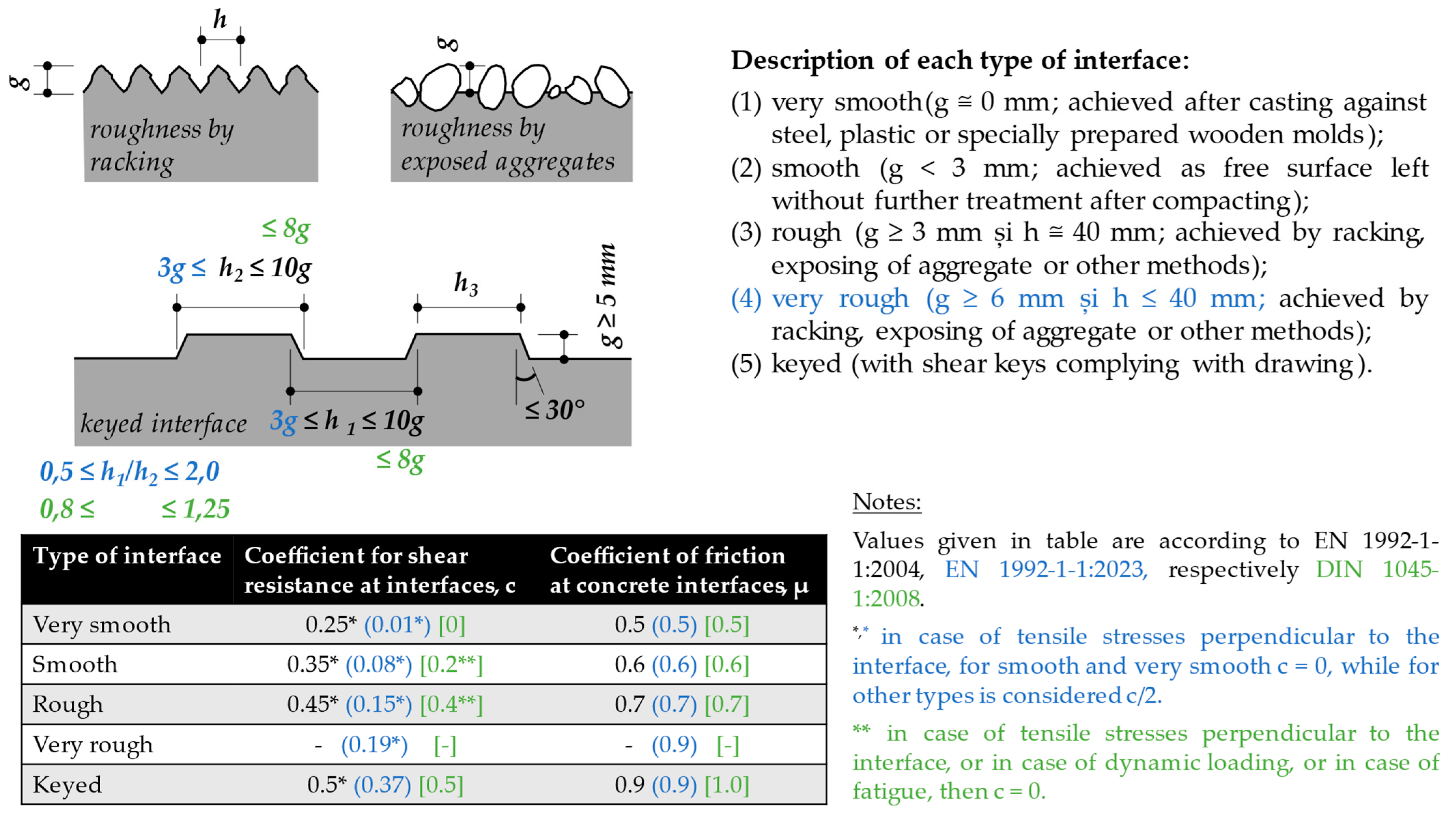
  • The coefficient of the shear resistance at interfaces, c, with the values given in the table shown in Figure 9;
  • The design value of the tensile strength of concrete, fctd;
  • The coefficient of friction at concrete interfaces, µ;
  • The compressive stress (with absolute value) acting perpendicular to the plane of the interface, σn ≤ 0.60·fcd, and if the normal stress at the interface surface is tensile, then it is considered in Equation (2) σn = 0.
The load-bearing capacity to longitudinal shear at the interface, without interface reinforcement, is calculated with EC2 (6.2.5 and Equation (6.25)) [1]:
τ R d i = m i n c · f c t d + μ · σ n ; 0.5 · υ · f c d
where it can be considered [57]:
σ n = C 1 · cos θ A i = V F d + T 3 b s t · t
The strength reduction factor for concrete cracked due to shear, ν, is calculated as:
υ = 0.6 · 1 f c k M P a 250
In the second generation of EC2 (8.2.6(5) and Equation (8.76), respectively, 10.7(2) and Equation (10.8)) [3], the load-bearing capacity to longitudinal shear at the interface without interface reinforcement is:
τ R d i = m i n c · f c k γ C + μ · σ n ; 0.3 · f c d
where fck denotes the characteristic concrete cylinder compressive strength, γC represents a partial safety factor for concrete, and fcd is the design value of the concrete compressive strength.

3.4. Dimensioning of the Slab Foundation (Isolated Footing)

The in-plane size of an individual footing, considering a shallow foundation type, must ensure the design requirements regarding the limitation of the maximum value of the earth pressure under the footing and must check the stability of the overturning of the foundation, respectively, and the limitation of its settlement and rotation. The footing of the pocket foundation is then dimensioned for punching, bending and shear.
Dimensioning for punching is carried out for the assembly phase (without infill concrete) considering the weight of the column multiplied by a dynamic coefficient γdin = 1.5 and considering the angle θ = 45°. Afterwards, for the final phase (after the monolithic concrete has been poured, hardened and reached the class given in the project) the design forces resulting from the structural analysis (for the ultimate limit state phase and possible intermediate phases) are used and also the bending moment capacity of the column (for seismic design) are considered. In this phase the check for punching is done in respect to the type of the precast column-pocket foundation joint interface (with smooth, rough or keyed surfaces), Figure 6, Figure 7 and Figure 8.
The bending moment and shear design are relevant in the cross-sections at the outside face of the pocket.
The equations for dimensioning for punching, bending moment and shear force can be used as given in EC2 [1].
Provisions regarding the reinforcement of the pocket foundation footing are as follows [1,2]:
(a)
Longitudinal reinforcement (bottom side):
  • Minimum reinforcement ratio in each direction: ρ s l , m i n = 0.1 % ;
  • Minimum diameter of the rebars used: ϕ s l , m i n = 10 mm;
  • Maximum and minimum distances between rebars: s l , m a x = 250   m m and s l , m i n = 100 mm;
  • Reinforcement will be anchored at the edge of the footing with l b , m i n [1] or with hooks having a length of 15 · ϕ s l [41] or of d (effective depth of the footing at the edge) [2].
(b)
Longitudinal reinforcement (top side): A minimum of three rebars in each direction, arranged orthogonally next to the column as a grid on the entire slab surface, is required. Foundations that do not detach from the ground are constructively reinforced, and those that work with an active area are reinforced based on the dimensioning to the negative bending moments in the critical cross-sections (in this case, the provisions for bottom reinforcement are also respected) [2].
(c)
Transversal reinforcement: If transverse reinforcement is required due to checking for punching, then inclined or vertical reinforcements will be arranged, respecting the reinforcement provisions specified in EC2 [1].

4. Case Study: Results

This case study aims to determine the tension forces in the pocket foundations for a long reinforced concrete column belonging to a single-story warehouse built of prefabricated concrete structural elements. For the precast reinforced concrete column characterized below (Figure 11, Table 2 and Table 3), the tension forces in the ties (from the corresponding strut-and-tie model) for each of the four types of pocket foundations are calculated (Table 4). The design forces calculated at the base of the column in the cross-section that is placed at the upper part of the pocket are noted in Table 3. For column–pocket foundation joints with keyed surfaces, the theoretical embedment depth of the column in the foundation to be used in the structural analysis of the superstructure is considered to be at the top of the pocket foundation in all of the cited literature sources. However, for the column–pocket foundation joints with smooth surfaces, the recommendations for the embedment depth vary; in most sources [1,3,5,58], it is recommended to be considered at the top of the pocket foundation. In the lectures on precast structures at TUCN, by Professor Kiss Z., it is indicated to be Hp/3, measured from the top to the bottom of the foundation, at t/2 or even at Hp/2 [59] (Ch. 12.2.5.1.1, Figure 12.21 and p. 388). However, for the case study presented below, the recommendations stated in the latest publications [1,3,5] are considered, which indicate that the fixation of the column in the foundation is to be established at the upper part of the pocket foundation, regardless of the type of the pocket foundation or the roughness of the interfaces in the joint.
Since the enforcement of the new European standard EC2 [3] for the design of reinforced concrete structures is planned for 2027, and the national annexes have not yet been developed, in this case study, the equations from EC2 [1] (which is the design standard enforced) are used for calculating the anchorage and overlap lengths of the rebars used in the dimensioning of the necessary reinforcement for the pocket foundations.

5. Discussion

Precast column–concrete infill–pocket foundation interface. When is it necessary to calculate the bearing capacity of the keyed precast column–concrete infill–pocket foundation interfaces? The calculation is required when one of the following situations occurs:
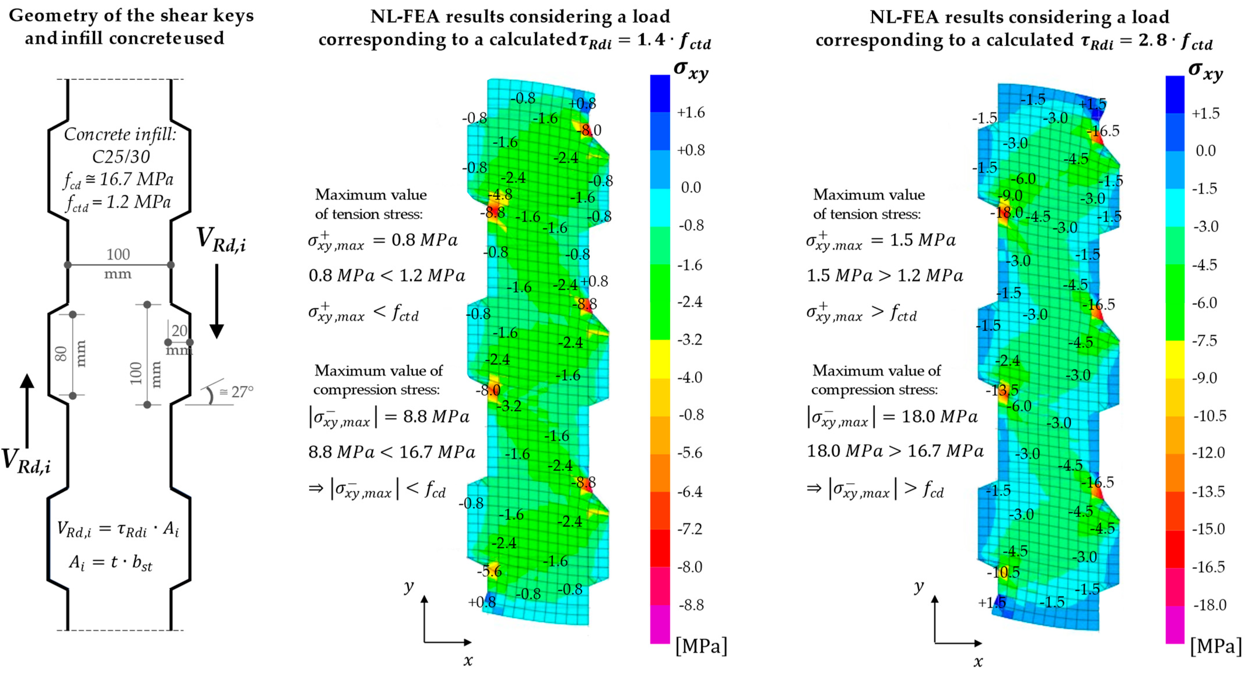
  • The geometry of the shear keys (castellation) does not comply with the provisions of the design norm;
  • The concrete used for filling the joint is not sufficiently fluid in its fresh state or shows shrinkage after hardening and drying;
  • The longitudinal reinforcement of the column is meant to be anchored directly in the foundation, and the castellation does not comply with the provisions of the design norm;
  • The castellation has been damaged to a great extent (e.g., during removal of the formwork, mounting, handling, etc.);
  • The column is subjected to large axial compression force (e.g., ν c o m p r e s i u n e = N F d / b s t · l s t · f c d 0.3 ) or when the column is subjected to axial tensile force.
Calculating castellation in a simplified way—the author’s proposal. In precast concrete column–pocket foundation keyed joints, the ensemble behaves like a caisson (characterized by a state of confinement). As a result, the surfaces of the joints cannot detach or move apart from each other. In this case, 0 ≤ σn ≤ 0.60·fcd can be considered. It is proposed that for a column subjected to pure compression, the transfer of the axial force to the foundation should be considered to be on the side faces of the pocket and the base of the column, with σn = 1.0·fctd (separation cannot take place), by equations in accordance with the design norm for reinforced concrete walls CR 2 -1-1.1/2013 (par. 7.6.3 and Equation (7.18)) [60] and with its previous edition CR 2-1-1.1/2006 [61], where, for vertical joints with shear keys between precast wall panels, the shear strength of a concrete indentation (tooth) is τRd = 1.5·fctd. Finally, the following equation is written to calculate the shear strength of the joint with keyed surfaces:
τ R d i = m i n 0.5 · f c t d + 0.9 · 1.0 · f c t d ; 0.5 · 0.5 · f c d m i n 1.4 · f ctd ; 0.25 · 14 · f c t d = 1.4 · f c t d
For columns subjected to axial compressive force combined with shear force and bending moment, it is recommended to accurately calculate the value of σn. If σn is greater than 1.0·fctd, use the calculated result. Otherwise, use σn = 1.0·fctd. Under normal working conditions, a separation between the precast column, infill concrete and pocket foundation does not occur due to the significant out-of-plane bending stiffness of the pocket walls.
It is also proposed that the beneficial effect of the confinement of the column–infill concrete interface is to be introduced in the dimensioning equations for keyed joints. This can be achieved by considering the interface area, Ai, as the lateral area of the columns embedded in the pocket (as in NP 112-2014 [2]) and not just the area of all the individual shear keys placed on one side (as it might be interpreted from EC2 [1] when designing structural joints with keyed surfaces). The previous recommendation also applies to the beneficial effects of confinement at the interface between the infill concrete and the pocket foundation. Additionally, when dimensioning the keyed interfaces for column–pocket foundation joints, the shear strength is treated similarly to that of a monolithic element. As stated in [1] (par. 10.9.6.2(1)), pocket foundations with keyed surfaces can be considered to act monolithically with the column. The shear stress resistance at the interface between two monolithically cast concrete elements (e.g., a coupling beam–column) is defined as τRdi = 1.0·fctd for DCH and τRdi = 1.5·fctd for DCM, according to CR 2-1-1.1/2013, (par. 7.7.2, Equations (7.19) and (7.20)) [60]. For the shear stress strength of a monolithic concrete wall, the same regulation (par. 7.6.2. with Equations (7.8) and (7.9)) [60] recommends using τRdi = 0.15·fcd ≅ 2.1·fctd for DCH and τRdi ≅ 0.18·fcd ≅ 2.5·fctd for DCM. Additionally, Kiss Z. advises [5] to use τRdi = 1.5·fctd in the calculation of the toping–beam/wall joint (chap. 4.5.4 and Equation (4.84)). Based on the provisions from the technical regulations enforced (for wall-, plate- and beam-type elements) and in the absence of specific provisions for column–pocket foundation joints with keyed internal walls, based on the previous equations, one can consider as conservative τRdi ≅ 1.4·fctd. This value can serve as a reference value for the shear stress strength of the concrete in the column–infill concrete–pocket foundation ensemble with keyed interfaces.
To verify the proposed equation, a nonlinear finite element analysis (NL-FEA) was conducted using C25/30 infill concrete. The results (Figure 12) show that, for an applied load corresponding to a shear stress of τEdi = 1.4·fctd, the concrete’s compressive and tensile strengths remained below the upper limit. However, when the load was doubled, the compressive strength was exceeded by approximately 10% and the tensile strength by around 20%. The stress distribution obtained from the NL-FEA illustrates the formation of diagonal compression struts, confirming the development of the mechanical model depicted in Figure 10.

6. Conclusions

Best practices for ensuring stability during the construction phase in regions prone to high winds or seismic activity are necessary. As a lesson from the before-mentioned progressive collapse of the columns, Section 2.2 paragraph (j), such accidents might be avoided if, during the assembly phase, the following are taken into account and double-checked: the oak wedges have the correct geometry and no soft wood is used; the size of the gap between the column and foundation is the minimum necessary for proper concreting and is designed separately for each type of column–foundation connection; in the structural design of the columns, wind and seismic actions are considered for the assembly phase; and slender columns during the assembly phase are propped.
This paper enhances the understanding of the design and dimensioning of precast concrete column–pocket foundation connections. The strut-and-tie models and the equations for the internal forces are presented in a unified manner (Figure 6, Figure 7 and Figure 8) and extended for seismic-resistant structures, making the structural engineering work easier and providing resilient column–pocket foundation joints. Additionally, the simplified calculation proposed by the authors for castellations, and validated via an NL-FEA, is another valuable tool that can be used by the structural engineer to dimension the keyed interface or to verify more sophisticated calculations.
Finally, analyzing the results of the calculations performed for the case study, we can conclude the following:
  • The shear stress resistance, τRd,i, is greater than the design value of shear stress, τEd,i, for all four types of pocket foundations studied. This means that the pre-dimensioning mathematical expressions led to a correct final geometry of each of the pocket foundations. Meanwhile, the ratio of longitudinal reinforcement in the column is 1.2% compared to the maximum permitted value of 4.0% [1,2,6]. It is expected that for heavily reinforced columns, increased pocket heights, Hp, will be required, which means that a pre-dimensioning with consideration of the MEd/NEd ratio, as indicated in the new EC2 standard [3], could provide Hp values closer to those required in the final design;
  • The interface area, Ai, was taken as the area of the entire lateral side of the column over the pocket depth for all interface types. In comparison, pocket foundations with rough internal walls exhibited an 18% increase in shear resistance, VRd,i, over those with smooth internal walls, while those with keyed internal walls showed a 26% increase, even though pockets with keyed internal walls are 8% shorter than those with smooth or rough internal walls. The values obtained seem plausible, and when interpreting them from the perspective of the roughness of the column–filled concrete interface, as the roughness increases, so does the shear resistance. However, this conclusion regarding joints with keyed interfaces becomes interpretable according to the text in EC2 [1] (par. 6.2.5(1)) and the one in the new EC2 [3] (par. 8.2.6(4)). Which states that for the area of a joint, Ai, one should consider either the area of all individual shear keys placed on one side or the keyed surface as a whole;
  • Pocket foundations with keyed internal walls are more efficient than those with smooth or rough walls. This foundation type requires 30% to 37% less reinforcement area and reduces pocket heights by 8%. Even though in terms of working hours and constructability, the use of castellation is slightly more expensive when compared to smooth joints, when the overall cost is considered (especially the material savings in terms of concrete and reinforcing steel), it is more economical. Furthermore, considering the enhanced structural performance (keyed surfaces are more capable of resisting tension in the column), pocket foundations with keyed internal walls may be the optimal choice, especially for long-term performance.
Future research directions. Further optimization of the superstructures made of reinforced concrete is in great demand. The authors are now focusing on two approaches for reducing the self-weight of long precast concrete columns for structures designed for seismic areas. The first consists of developing prestressed reinforced concrete columns with integrated viscous elastic damping and self-centering capacity, bioinspired by coniferous trees [62,63,64,65,66,67,68,69]. The use of such self-centering prestressed columns endowed with viscous elastic damping might allow a reduction in the concrete cross-section (slender columns), but the bending and shear strength needs to be maintained. From here, it follows that the tensile forces in the ties (T1, T2 and T3), the compression force in the struts (C1–C9) and the stress in the shear keys will increase due to the shorter lever arms. If thicker concrete sections for the pocket and slab’s foundation will not be enough and neither larger compression resistance of higher concrete grades, a solution for this would be to develop new strut and tie models. And second, reducing the self-weight of the column through variations of the concrete’s density [70,71,72,73] in respect to the ratio of the utilization factor in each cross section. A difficult issue with changing the concrete density inside a structural element is delamination. To prevent delamination, additional transversal reinforcement is required, and this involves an upgrade of the strut-and-tie models to include some additional ties. In both cases, the design method with a strut-and-tie model needs to be further studied for each type of pocket foundation and adapted if applicable.

Supplementary Materials

The following supporting information can be downloaded at: https://drive.google.com/drive/folders/17qg7bHGTxoXyvc-8HCvpNThswc3lt2VD?usp=sharing (accessed on 11 October 2024), Figures S1–S9: Insufficient temporary fixing of long prefabricated concrete columns in pocket foundations due to strong wind conditions caused collapse with a domino effect; Video S1: The collapse of the columns fixed with wooden wedges under the action of a gust of wind; Video S2: A row of 11 columns after collapse, of which 1 is intact, 2 are tilted and 8 are broken; Figures S10–S15 execution of pocket foundations with prefabricated socket and keyed internal walls, respectively; Figures S16–S20: execution of pocket foundations with monolithic socket and keyed internal walls.

Author Contributions

Conceptualization, T.-N.T.; methodology, T.-N.T.; drawings, T.-N.T.; validation, H.C. and T.-N.T.; formal analysis, T.-N.T.; data curation, H.C.; writing—original draft preparation, T.-N.T.; writing—review and editing, H.C. and T.-N.T.; visualization and translation, T.-N.T.; supervision, H.C. All authors have read and agreed to the published version of the manuscript.

Funding

The authors gratefully acknowledge the financial support from the Technical University of Cluj-Napoca, under GNAC ARUT 2023, and funding the research grants with registration number 7/01-07-2024, ID 6834, namely “Structuri cu Amortizare vâscoelastică și capacitate de Auto-centrare Bioinspirate de Arbori Coniferi (RO)/Structures with viscoelastic damping and self-centering capacity bioinspired by Spruce trees (EN)”, and registration number 9/01-07-2024, ID 8772, namely “Elemente structurale hibride din beton armat formate din straturi de densități diferite (RO)/Hybrid structural reinforced concrete elements made of layers with different densities (EN)” https://research.utcluj.ro/index.php/lansare-competitii.html (accessed on 11 October 2024).

Data Availability Statement

The data that support the findings of this study are available from the corresponding author upon reasonable request.

Acknowledgments

The authors express their special thanks to Kiss Zoltán I. for all the know-how regarding reinforced concrete, prestressed concrete and prefabricated concrete structures that he shared with them during the last two decades. Also, for sharing materials from the recent failure of some prefabricated concrete columns temporarily fixed in the pocket foundations and subjected to extreme wind, special thanks are sent to Țere Sergiu-Gheorghe. The authors are thankful to the precast concrete factory S.C. ASA Cons S.R.L. from Turda, Romania, for their good collaboration regarding the details of good practices for the execution of precast concrete columns and foundations. For her suggestion to include a detailed structural design of the column–foundation keyed connection as part of the teaching classes in the Geotechnical Engineering master program, Faculty of Civil Engineering, at the Technical University of Cluj-Napoca, the authors express their gratitude to Ilieș Nicoleta M., as it was a true encouragement for them to elaborate further on the theoretical fundamentals, bring it up to date, and validate and elaborate several case study examples. Last but not least, the authors express gratitude to CSI Romania for offering a free software license of ETABS and SAP 2000.

Conflicts of Interest

The authors declare no conflicts of interest.

References

  1. Comité européen de normalisation (CEN). Eurocode 2: Design of Concrete Structures—Part 1-1: General Rules and Rules for Buildings (Abbreviated EN 1992-1-1, Informally EC2); CEN: Brussels, Belgium, 2004; Available online: https://eurocodes.jrc.ec.europa.eu/EN-Eurocodes/eurocode-2-design-concrete-structures (accessed on 11 October 2024).
  2. Ministerul Dezvoltării, Lucrărilor Publice și Administrației (MDLPA). Normativ privind proiectarea fundațiilor de suprafață (Abbreviated NP 112-2014); MDLPA: București, Romania, 2014; Available online: https://www.mdlpa.ro/userfiles/reglementari/Domeniul_III/III_26_NP_112_2014.pdf (accessed on 11 October 2024).
  3. Comité européen de normalisation (CEN). Eurocode 2: Design of Concrete Structures—Part 1-1: General Rules and Rules for Buildings, Bridges and Civil Engineering Structures (Second Generation Eurocode 2, Abbreviated EN 1992-1-1, Informally EC2); CEN-CENELEC: Brussels, Belgium, 2023; Available online: https://www.en-standard.eu/bs-en-1992-1-1-2023-eurocode-2-design-of-concrete-structures-general-rules-and-rules-for-buildings-bridges-and-civil-engineering-structures/?srsltid=AfmBOoryekhTQ2PA6WdsiM-Sr8yCvPSKc00BC7Xn_5rTmIZPc9AUJ4Ah (accessed on 11 October 2024).
  4. Muteb, H.; Hasan, H.; Al-Baghdadi, H. Interaction between Precast Concrete Columns with Socket Foundations Using Different Bonding Interfaces. In Proceedings of the 3rd International Conference on Architectural and Civil Engineering, Cihan University-Erbil Conferences, Erbil, Iraq, 5–6 April 2021. [Google Scholar] [CrossRef]
  5. Kiss, Z.I. Structuri Prefabricate de Beton Armat. Recomandări Pentru Alcătuirea Constructivă și Dimensionarea Structurilor în Cadre; Abel: Cluj-Napoca, Romania, 2024; Available online: https://www.abelkiado.ro/ro/carte/3715/structuri-prefabricate-de-beton-armat/recomandari-pentru-alcatuirea-constructiva-i-dimensionarea-structurilor-in-cadre (accessed on 11 October 2024).
  6. Ministerul Dezvoltării, Lucrărilor Publice și Administrației (MDLPA). Cod de Proiectare Seismică—Partea 1: Prevederi de Proiectare Pentru Clădiri (Abbreviated P100-1/2013); MDLPA: București, Romania, 2019; Available online: https://www.mdlpa.ro/userfiles/reglementari/Domeniul_I/I_22_P100_1_2013.pdf (accessed on 11 October 2024).
  7. Tillmann, M. Knotenverbindungen für Betonfertigteile. Hinweise für Bemessung und Konstruktion; Fachvereinigung Deutscher Betonfertigteilbau e.V. 2011. Available online: https://www.bft-international.com/de/news/fdb-fachbroschuere-knotenverbindungen-fuer-betonfertigteile-ueberarbeitet-3429967.html (accessed on 11 October 2024).
  8. Liu, B.; Zhang, L.; Sun, H.; Feng, M.; Dou, K. Side shear strength and load-transfer mechanism of corrugated steel column–foundation socket connection. Case Stud. Constr. Mater. 2022, 17, e01377. [Google Scholar] [CrossRef]
  9. Steinle, A.; Bachmann, H.; Tillmann, M. Precast Concrete Structures, 2nd ed.; Ernst & Sohn (Wiley): Berlin, Germany, 2019; Available online: https://www.ernst-und-sohn.de/precast-concrete-structures-ebundle (accessed on 11 October 2024).
  10. Steinle, A.; Bachmann, H.; Tillmann, M. Bauen mit Betonfertigteilen im Hochbau (BetonKalendar 2016—Kapitel III); Ernst & Sohn (Wiley): Berlin, Germany, 2016; Available online: https://www.ernst-und-sohn.de/beton-kalender-2016 (accessed on 11 October 2024).
  11. Bachmann, H.; Tillmann, M.; Urban, S. Bauen mit Betonfertigteilen im Hochbau (BetonKalendar 2021); Ernst & Sohn (Wiley): Berlin, Germany, 2021; Available online: https://onlinelibrary.wiley.com/doi/abs/10.1002/9783433610206.ch2 (accessed on 11 October 2024).
  12. Comité européen de normalisation (CEN). Design of Structures for Earthquake Resistance—Part 1: General Rules, Seismic Actions and Rules for Buildings (Abbreviated EN 1998, Informally EC8); CEN: Brussels, Belgium, 2004; Available online: https://eurocodes.jrc.ec.europa.eu/EN-Eurocodes/eurocode-8-design-structures-earthquake-resistance (accessed on 11 October 2024).
  13. DIN Norm. Tragwerke aus Beton, Stahlbeton und Spannbeton—Teil 1: Bemessung und Konstruktion (abbreviated DIN 1045-1), DIN Norm. 2008. Available online: https://www.baunormenlexikon.de/norm/din-1045-1/1ce039fc-a3e6-4f97-a670-38950b599945 (accessed on 11 October 2024).
  14. Popa, A.; Ilieș, N.-M. Fundații; Casa Cărții de Știință: Cluj-Napoca, Romania, 2013; Available online: https://www.casacartii.ro/editura/carte/fundatii/ (accessed on 11 October 2024).
  15. Toader, T.-N. Stabilirea Specificației Betonului de Ciment Proaspăt și întărit, Conform SR EN 206-1, 2nd ed.; UTPRESS: Cluj-Napoca, Romania, 2023; Available online: https://biblioteca.utcluj.ro/files/carti-online-cu-coperta/632-6.pdf (accessed on 11 October 2024).
  16. Ionescu, A. Construcții de Beton Armat I și II—Note de Curs; Specializarea CCIA, Facultatea de Construcții—Universitatea Tehnică din Cluj-Napoca: Cluj-Napoca, Romania, 2007. [Google Scholar]
  17. Sparowitz, L. Vorlesungsskriptum aus Betonbau; Institut für Betonbau—Technische Universität Graz, Fachbereichs Ingenieurbaukunst (IBK) and der TU Graz: Graz, Austria, 2004. [Google Scholar]
  18. Zilch, K.; Zehetmeier, G. Bemessung im Konstruktiven Betonbau (2. Auflage), 2nd ed.; Nach Din 1045-1 (Fassung 2008) und EN 1992-1-1 (Eurocode 2); Springer: Berlin/Heidelberg, Germany, 2010. [Google Scholar]
  19. Plan_31_Ro. Fotografii din Timpul Execuției Proiectelor Realizate în Colectivul de Proiectare; Arhiva Biroului de proiectare: Cluj-Napoca, Romania, 2015. [Google Scholar]
  20. Elliot, K.S.; Jolly, C.K. Multi-Storey Precast Concrete Framed Structures; Wiley Blackwell: West Sussex, UK, 2013; Available online: https://www.wiley.com/en-au/Multi-Storey+Precast+Concrete+Framed+Structures%2C+2nd+Edition-p-9781405106146 (accessed on 11 October 2024).
  21. Bachmann, H.; Steinle, A. Precast Concrete Structures; Ernst & Sohn (Wiley): Berlin, Germany, 2011; Available online: https://onlinelibrary.wiley.com/doi/book/10.1002/9783433600962 (accessed on 11 October 2024).
  22. Hierlein, E.; Tillmann, M.; Brandt, J.; Rösel, W.; Schwerm, D.; Stöffler, J. Betonfertigteile im Geschoss- und Hallenbau. Grundlagen für die Planung, 3rd ed.; FDB—Fachvereinigung, Deutscher Betonfertigteilbau e.V.: Bonn, Germany; Verlag Bau + Technik GmbH: Düsseldorf, Germany, 2021; Available online: https://www.fdb-fertigteilbau.de/fileadmin/user_upload/broschueren/FDB_Geschoss-_und_Hallenbau_2021_Webdatei.pdf (accessed on 11 October 2024).
  23. Ge, J.; Lai, L.; Liu, S.; Yan, X. Ultimate Bearing Capacity Analysis of Pile Caps with New Socket Connections. Buildings 2022, 12, 2034. [Google Scholar] [CrossRef]
  24. Deutscher Beton- und Bautechnik-Verein E.V. Beispiele zur Bemessung nach Eurocode 2; Band 1: Hochbau; Ernst & Sohn (Wiley): Berlin, Germany, 2012; Available online: https://www.ernst-und-sohn.de/beispiele-zur-bemessung-nach-eurocode-2-band-1 (accessed on 11 October 2024).
  25. Leonhardt, F.; Mönnig, E. Vorlessungen über Massivbau. Dritter Teil—Grundlagen zum Bewehren im Stahlbetonbau; Springer: Berlin/Heidelberg, Germany, 1975; Available online: https://link.springer.com/book/10.1007/978-3-662-10822-2 (accessed on 11 October 2024).
  26. Hemamathi, L.; Jaya, K. Behaviour of Precast Column Foundation Connection under Reverse Cyclic Loading. Adv. Civ. Eng. 2021, 2021, 17. [Google Scholar] [CrossRef]
  27. Aboukifa, M.; Reyad, K.; Saad, F. Behavior and Design of Precast Column/Base Pocket Connections with Smooth Surface Interface. CERM 2017, 39, 191–202. Available online: http://www.azharcermjournal.com/CERMF1707/P17-07-16.pdf (accessed on 11 October 2024).
  28. Canha, R.; Jaguaribe, K.; El Debs, A.; El Debs, M. Analysis of the behavior of transverse walls of socket base connections. Eng. Struct. 2009, 31, 788–798. [Google Scholar] [CrossRef]
  29. Hemamathi, A.; Jaya, K.P.; Sukumar, B. Evaluation of Ductility of Precast Column Foundation Connections. Indian J. Sci. Technol. 2023, 16, 1516–1526. [Google Scholar] [CrossRef]
  30. Tazarv, M.; Saiidi, M.S. Design and Construction of Precast Bent Caps with Pocket Connections for High Seismic Regions; University of Nevada, Reno, Center for Civil Engineering Earthquake Research: Reno, Nevada, 2015; Available online: https://rosap.ntl.bts.gov/view/dot/41828/dot_41828_DS1.pdf (accessed on 11 October 2024).
  31. Zhiqiang, G.W.; Li, T.; Qu, H.; Wei, H.; Li, Y. Seismic Performance of Precast Bridge Columns with Socket and Pocket Connections Based on Quasi-Static Cyclic Tests: Experimental and Numerical Study. J. Bridge Eng. 2019, 24. [Google Scholar] [CrossRef]
  32. Jiang, X.; Li, J.; Liu, P.; Qu, H.; Gao, J.; Bao, Z. Seismic performance of precast bridge bents with prestressed piles and new pocket connection design: Experimental and numerical study. Soil Dyn. Earthq. Eng. 2024, 183, 16. [Google Scholar] [CrossRef]
  33. Luo, Z.; Wang, Y. Experimental and numerical investigations of the impact resistance of socket and pocket connections for precast bridge columns. Structures 2024, 64, 106631. [Google Scholar] [CrossRef]
  34. Comité européen de normalisation (CEN). EN 206:2013+A2:2021 Concrete Specification, Performance, Production and Conformity; CEN-CENELEC: Brussels, Belgium, 2021; Available online: https://www.en-standard.eu/bs-en-206-2013-a2-2021-concrete-specification-performance-production-and-conformity/?srsltid=AfmBOoqTIJ6Ti1oDN_Ce3bkCDPCahg5kFA-9dgct7gELTIJUL4KC4Gqs (accessed on 11 October 2024).
  35. Ministerul Dezvoltării, Lucrărilor Publice și Administrației (MDLPA). NE 012/1-2022 Normativ Pentru Producerea și Executarea Lucrărilor din Beton, Beton Armat şi Beton Precomprimat—Partea 1: Producerea Betonului; MLPAT: București, Romania, 2023; Available online: https://www.mdlpa.ro/uploads/articole/attachments/63d7c00311fba319161394.pdf (accessed on 11 October 2024).
  36. Ministerul Dezvoltării, Lucrărilor Publice și Administrației (MDLPA). NE 012/2-2022 Normativ Pentru Producerea și Executarea Lucrărilor din Beton, Beton Armat și Beton Precomprimat—Partea 2: Executarea Lucrărilor din Beton; MLPAT: București, Romania, 2023; Available online: https://www.mdlpa.ro/uploads/articole/attachments/63d7c09bb537f654267470.pdf (accessed on 11 October 2024).
  37. Golewski, G. Specificity of Shaping and Execution of Monolithic Pocket Foundations (PF) in Hall Buildings. Buildings 2022, 12, 192. [Google Scholar] [CrossRef]
  38. Tomșa, F.; Sima, T.; Gottfried, I. Cartea Montatorului de Prefabricate (Ediția a 3a); Editura Tehnică: București, Romania, 1972. [Google Scholar]
  39. Kiss, Z.I.; Oneț, T. Proiectarea Structurilor de Beton După SR EN 1992-1-1; Abel: Cluj-Napoca, Romania, 2010; Available online: https://www.abelkiado.ro/ro/carte/1164/proiectarea-structurilor-de-beton-dupa-sr-en-1992-1-ed-ii-revizuita-coperta-subire/curs-universitar (accessed on 11 October 2024).
  40. Leviat a CRH Company. Modersohn Stainless Steel, www.modersohn.eu. Available online: https://www.modersohn.eu/industrie/detailseite/zentriersysteme-fuer-fertigteile/ (accessed on 5 April 2024).
  41. Ministerul transporturilor, construcțiilor și turismului (MTCT). Normativ Privind Proiectarea Fundațiilor de Suprafață (Abbreviated NP 112-2004), Monitorul Oficial Al României, Partea I, nr. 451 din 27 mai 2005: București, Romania. 2005. Available online: https://www.academia.edu/29215744/NP_112_04_normativ_fundatii (accessed on 11 October 2024).
  42. Associação Brasileira de Normas Técnicas. NBR 9062—Design and Execution of Precast Concrete Structures (în Portugheză: Projeto e Execução de Estruturas de Concreto Pré-moldado); ABNT: Sao Paulo, Brazil, 2017; Available online: https://professor.pucgoias.edu.br/sitedocente/admin/arquivosUpload/14026/material/NBR9062_2017.pdf (accessed on 11 October 2024).
  43. Canha, R.M.F.; El Debs, M.K. Critical Analysis of Models and Recommendations for Designing Column-Base Connection by Socket of Precast Concrete Structures. IBRACON Struct. J. 2006, 2, 95–115. Available online: http://ibracon.org.br/publicacoes/revistas_ibracon/rev_estruturas/pdf/riest%20-%20vol2%20-%20n%C2%BA2%20-%20artigo%201-%20english.pdf (accessed on 11 October 2024).
  44. Santos, S.P. Connections of Precast Concrete Structures (in Portuguise: Ligações de Estruturas Prefabricadas de Betão); Laboratório Nacional de Engenharia Civil: Lisboa, Portugal, 1985. [Google Scholar]
  45. Yang, J.; Guo, T.; Zeng, C. Experimental investigation of seismic behavior of precast pier-footing socket connection with different design parameters. Struct. Concr. 2024, 25, 1938–1952. [Google Scholar] [CrossRef]
  46. Canha, R.; de Cresce El Debs, A.L.H.; El Debs, M. Design model for socket base connections adjusted from experimental results. Struct. Concr. 2007, 8, 3–10. [Google Scholar] [CrossRef]
  47. Canha, R.M.F.; El Debs, M.K.; Jaguaribe Junior, K.d.B.; El Debs, A.L.H.d.C. Behavior of Socket Base Connections Emphasizing Pedestal Walls. ACI Struct. J. 2009, 106, 268–278. [Google Scholar] [CrossRef]
  48. Pul, S.; Husem, M.; Arslan, M.E.; Hamzacebi, S. An experimental study on different socket base connections under cyclic loading. Comput. Concr. 2014, 13, 377–387. [Google Scholar] [CrossRef]
  49. El-Naqeeb, M.H.; Hassanli, R.; Zhuge, Y.; Ma, X.; Manalo, A. Numerical investigation on the behaviour of socket connections in GFRP-reinforced precast concrete. Eng. Struct. 2024, 303, 117489. [Google Scholar] [CrossRef]
  50. Campos, G.M.; Canha, R.M.F.; El Debs, M.K. Design of precast columns bases embedded in socket foundations with smooth interfaces. IBRACON Struct. Mater. J. 2011, 4. [Google Scholar] [CrossRef]
  51. Canha, R.; Ebeling, E.; El Debs, A.; El Debs, M. Analysing the base of precast column in socket foundations with smooth interfaces. Mater. Struct. 2009, 42, 725–737. [Google Scholar] [CrossRef]
  52. Cheng, Z.; Liu, D.; Li, S.; Wang, J.; Zhang, J. Performance characterization and design recommendations of socket connections for precast columns. Eng. Struct. 2021, 242. [Google Scholar] [CrossRef]
  53. Canha, R.M.F.; Campos, G.M.; El Debs, M.K. Design model and recommendations of column-foundation connection through socket with rough interfaces. IBRACON Struct. J. 2012, 5, 182–218. [Google Scholar] [CrossRef]
  54. Chen, W.; De Corte, H.; Jiang, H.; Taerwe, L. Experimental study on direct-shear behaviour of narrow joints in socket connections for precast pier-to-pile footing systems. Structures 2024, 61. [Google Scholar] [CrossRef]
  55. CEN European Committee for Standardization/ASRO. Eurocode 0: Basis of Structural Design/SR EN 1990:2004 + SR EN 1990/NA:2006, CEN/TC250; CEN: Bruxelles, Belgium, 2002; Available online: https://magazin.asro.ro/ro/standard/115449 (accessed on 11 October 2024).
  56. Albert, A. Bautabellen für Ingenieure mit Berechnungshinweisen und Beispielen, 21st ed.; Bundesanzeiger Verlag GmbH: Cologne, Germany, 2014; Available online: https://books.google.ro/books/about/Bautabellen_f%C3%BCr_Ingenieure.html?id=X0eSoAEACAAJ&redir_esc=y (accessed on 11 October 2024).
  57. Toader, T.-N. Structural Design of Keyed Surfaces for Precast Concrete Columns Embedded in Pocket Foundations. In Proceedings of the C70 International Conference “Tradition and Innovation—70 Years of Constructions in Transilvania”, Cluj-Napoca, Romania, 8 November 2023; Available online: https://c70.utcluj.ro/wp-content/uploads/2023/12/657-9-Constructii-70-min.pdf (accessed on 11 October 2024).
  58. Agent, R.; Bănuț, V. Calculul Structurilor din Beton Armat cu Stâlpi Zvelți; Editura Tehnică: București, Romania, 1979. [Google Scholar]
  59. Mîrșu, O.; Friedrich, R. Construcții din Beton Armat; Editura Didactică și Pedagogică: București, Romania, 1980. [Google Scholar]
  60. Ministerul Dezvoltării, Lucrărilor Publice și Administrației (MDLPA). Cod de Proiectare a Construcțiilor cu Pereți Structurali de Beton Armat; MDLPA: București, Romania, 2013; Available online: https://www.mdlpa.ro/userfiles/reglementari/Domeniul_I/I_21_CR_2_1_1_1_2013_completare.pdf (accessed on 11 October 2024).
  61. Ministerul Dezvoltării, Lucrărilor Publice și Administrației (MDLPA). Cod de Proiectare a Construcțiilor cu Pereți Structurali de Beton Armat; MDLPA: București, Romania, 2006. [Google Scholar]
  62. Toader, T.-N.; Mircea, C.-R.; Truta, A. Coniferous Trees as Bioinspiration for Designing Long. Biomimetics 2024, 9, 165. [Google Scholar] [CrossRef]
  63. Toader, N.; Sobek, W.; Nickel, K. Energy Absorption in Functionally Graded Concrete. J. Bionic Eng. 2017, 14, 369–378. [Google Scholar] [CrossRef]
  64. Pastrav, M.; Constantinescu, H. Seismic Behavior of Self-Balancing Post-Tensioned Reinforced Concrete Spatial Structure, World Academy of Science, Engineering and Technology. Int. J. Civ. Environ. Struct. Constr. Archit. Eng. 2016, 10. Available online: https://publications.waset.org/10005784/seismic-behavior-of-self-balancing-post-tensioned-reinforced-concrete-spatial-structure (accessed on 11 October 2024).
  65. fib Bulletin, No. 27 Seismic Design of Precast Concrete Building Structures; State-of-art Report; fib CEB FIP: Lausanne, Switzerland, 2003. [CrossRef]
  66. fib Bulletin, No. 43 Structural Connections for Precast Concrete Buildings; Guide to Good Practice; fib CEB FIP: Lausanne, Switzerland, 2008. [CrossRef]
  67. fib Bulletin, No. 78 Precast-Concrete Buildings in Seismic Areas; State-of-the-art report; fib CEB FIP: Lausanne, Switzerland, 2016. [CrossRef]
  68. Toader, T.N.; Schmeer, D.; Sobek, W. Concept for an Onshore Tower Structure Made of UHPFRC Segments for Wind Turbines. Acta Tech. Napoc. Civ. Eng. Archit. 2019, 62, 1. Available online: https://oldconstructii.utcluj.ro/ActaCivilEng/download/atn/ATN2019(1)_1.pdf (accessed on 11 October 2024).
  69. Nickel, K.; Klang, K.; Toader, N.; Sobek, W. The potential of improving building construction materials by a biomimetic approach. In Proceedings of the 10th International Conference on Emerging Materials and Nanotechnology, Vancouver, BC, Canada, 27–29 July 2017. [Google Scholar] [CrossRef]
  70. Toader, N.; Haase, W.; Sobek, W. Energy Absorption in Functionally Graded Concrete under Compression, Bul. Institutului Politeh. Iasi—Sectia Constr. Arhit. 2018, 64, 9–23. Available online: https://www.bipcons.ce.tuiasi.ro/Content/ArticleInformation.php?ArticleID=654 (accessed on 11 October 2024).
  71. Butean, C.; Heghes, B. Flexure behavior of a two layer reinforced concrete beam. Procedia Manuf. 2020, 46, 110–115. [Google Scholar] [CrossRef]
  72. Butean, C.; Heghes, B. Cost efficiency of a two layer reinforced concrete beam. Procedia Manuf. 2020, 46, 103–109. [Google Scholar] [CrossRef]
  73. Puskas, A.; Zagon, R.; Szilagyi, H.; Corbu, O.; Baerã, C.; Constantinescu, H. Modelling of the bending behaviour of double floor systems for different contact surfaces. Constructii 2014, 15, 46–53. [Google Scholar]
Figure 2. Exemplifying the characterization of concrete by classes on a structural joint between precast concrete column–pedestal pocket foundation.
Buildings 14 03466 g002
Figure 3. Details of precast concrete column mounting in the foundation and centering device. Adapted from [39] and stylized photos with branded products [40].
Buildings 14 03466 g003
Figure 4. Temporary support of prefabricated columns belonging to a frame structure, considering [5,20].
Buildings 14 03466 g004
Figure 5. Precast concrete column–pedestal pocket foundation joint. Adapted from [2].
Buildings 14 03466 g005
Figure 6. Calculation model for pedestal pocket foundation (integrally monolithic: socket and slab foundation) with smooth or rough internal walls: (a) Strut-and-tie model and (b) normal forces on the inner surfaces of the pocket and associated friction forces, considering [1,2,3,5,6,7,25]. Struts C7-8 appear due to shear force action, VFd; struts C1–6 due to eccentric compression; and strut C9 due to the combined action of the shear and eccentric compression. Tie T2 appears due to shear force action, Ties T1 and T3 due to bending moment, and ties T4 and T5 due to the combined action of shear force and eccentric compression. C1 ≥ T3, C3 = T2 + T3, and C7 = (T2 + T3)/cosθ are the compressive force in the other struts depending on the geometry of the foundation, the coefficient of friction that characterizes the foundation–column joint, the axial forces in the column in the intermediate phases of the construction and the position of the reinforcement. The anchorage and overlapping lengths are indicated in EC2 from 2004 [1] and NP 112-2014 [2]. The height of the pocket will be chosen in such a way as to ensure the anchorage length of the vertical reinforcement in the column. The anchoring lengths lbd,jos and lbd,inf are measured from the intersection point of the struts with the ties T4 and T5, respectively (at the intersections C6, C8 and C9). The rebar ϕs,pv will overlap the bottom reinforcement in the slab’s foundation.
Buildings 14 03466 g006
Figure 7. Calculation model for pedestal pocket foundation (with precast socket and monolithic slab foundation) with keyed internal walls: (a) Strut-and-tie model and (b) vertical reinforcement overlapping, considering [1,2,3,5,6,7,9,11,24]. Strut C7 appears due to shear force action, VFd; struts C1–4 are due to eccentric compression; struts C5–6 are due to combined shear and eccentric compression. Tie T2 appears due to shear force action, tie T3 due to the bending moment, and tie T1 due to the combined action of the two. C1 = C3 = Fs/cosθ, and C7 = (T2 + T3)/cosθ are the compressive force in the other struts depending on the geometry of the foundation, the axial forces in the column in the intermediate phases of the construction and the position of the reinforcement. The anchorage and overlapping lengths are indicated in EC2 din 2004 [1]; however, according to the German literature [5,7,9,11,24], the anchorage and overlapping lengths can be substantially reduced. The height of the pocket will be chosen in such a way as to ensure the overlap lengths for the vertical rebars in the pocket with those in the column. The anchoring length lbd,jos is measured from the intersection point of the strut C6 with the tie T4.
Buildings 14 03466 g007
Figure 8. Calculation model for pad foundation with pocket and keyed internal walls: (a) Strut-and-tie model and (b) vertical reinforcement overlapping, considering [1,2,3,5,6,7,9,11,24]. Struts C7–8 appear due to shear force action, VFd; struts C1–6 are due to eccentric compression. Ties T1 and T3 appear due to eccentric compression, and ties T4–5 are due to the combined action of shear force and eccentric compression. C1 = C3 = Fs/cosθ, and C7 = (VFd + T3)/cosθ are the compressive force in the other struts depending on the geometry of the foundation, the axial forces in the column in the intermediate phases of the construction and the position of the reinforcement. The anchorage and overlapping lengths are indicated in EC2 din 2004 [1]; however, according to the German literature [5,7,9,11,24], the anchorage and overlapping lengths can be substantially reduced. The height of the pocket will be chosen in such a way as to ensure the lap lengths for the vertical reinforcement in the pocket with those in the column. The anchoring lengths lbd,jos and lbd,inf are measured from the intersection point of the struts with the ties T4 and T5, respectively. The rebar ϕs,pv will overlap the bottom reinforcement in the slab’s foundation.
Buildings 14 03466 g008
Figure 9. Classification of interfaces, according to EN 1992-1-1:2004 [1], EN 1992-1-1:2023 [3] (values and specifications are colored in blue) and DIN 1045-1:2008 [13] (values and specifications are colored in blue).
Buildings 14 03466 g009
Figure 10. Mechanical model of a shear key, possible failure mechanisms for castellation [20], examples of compliant geometries for shear keys on the base of the column and on the internal walls of the pocket foundation, and a rubber molding is to be placed on the formwork in the area that is meant to have the keyed interface.
Buildings 14 03466 g010
Figure 11. Input data for the precast reinforced concrete column: geometry, reinforcement and bending moment–curvature (MRd-1/r) interaction diagrams and bi-directional bending moment–axial force (MRdy-MRdz-NEdx).
Buildings 14 03466 g011
Figure 12. Stress state (σxy) in the infill concrete on the deformed shape after NL-FEA, considering material and geometry as nonlinearities. The load applied was calculated with Equation (1), considering the shear stress equal to the shear strength.
Buildings 14 03466 g012
Table 1. Pre-dimensioning of the pocket foundation (bp and Hp) using, as bibliographic references, the lecture notes of the pioneering professor in reinforced and prestressed concrete, Fritz [25], respectively, and modern design standards from Europe [1,3], Romania [2,6,41] and Brazil [42].
Type of SurfacePocket’s Wall Thickness
bp
Depth of the Pocket
Hp
Bibliographic Source
smooth m a x m i n l s t + 2 · f ; b s t + 2 · f / 3 100   m m f H + m a x l s t ; b s t · 1.2 · 1.4 d a c ă   M R d . s t / N E d . s t 0.15
f H + m a x l s t ; b s t · 2.0 · 1.4 d a c ă   M R d . s t / N E d . s t 2.00
Leonhardt and Mönnig (1975) [25]
rough f H + m a x l s t ; b s t · 1.2 d a c ă   M R d . s t / N E d . s t 0.15
f H + m a x l s t ; b s t · 2.0 d a c ă   M R d . s t / N E d . s t 2.00
For the intermediate values of the ratio between the value of the bending moment and that of the axial force, a linear interpolation is to be used.
smooth
rough
keyed
m a x 1.5 · M R d . 1 / H P + V E d . s t / H P · f c t d 200   mm   ( monolithic )   150   mm   ( prefabricated )
where, correlated with the direction of VEd.st, we have:
M R d . 1 = m a x M R d . s t N E d . s t · l 0 / 3 ; M R d . s t / 2
or
M R d . 1 = m a x M R d . s t N E d . s t · b 0 / 3 ; M R d . s t / 2
m a x m a x l s t ; b s t · 1.2 500   mm H s / 11     ( * * ) l b d , s t + 250   mm M R d . s t / 3 · l s t · b s t · f c t d , s t NP 112-*04 (2004) [41]
smoothNo specification. f H + m a x l s t ; b s t · 1.2 EN 1992-1-1:2004 (2004) [1]
keyed l 0 , p v + s + f H + c n o m . s t + c n o m . p v
smooth
rough
m a x m i n l s t ; b s t / 3 200   mm   ( monolithic )   150   mm   ( prefabricated ) m a x m a x l s t ; b s t · 1.2 500   mm H s / 8     ( * ) l b d , s t v + 100   m m NP 112-2014 (2014) [2]
keyed m a x m a x l s t ; b s t · 1.2 500   mm H s / 8     ( * ) l b d , s t + 100   mm l 0 , p v + s + f H + c n o m . s t + c n o m . p v
For columns subjected to tensile axial force, the use of a column–pocket foundation joint with smooth internal walls is not permitted.
The longitudinal reinforcements of the columns subjected to tensile axial force in the seismic combination must be anchored with an anchorage length of 1.50·lbd. (par. 5.7.2.2(1)) [6] and (par. 5.6.2.1(2)) [12].
The longitudinal reinforcement in the critical areas of columns in structures designed for the high ductility class (DCH) requires anchoring to begin at a depth of 5·ϕsl within the element where the anchoring is performed (in the pocket). In addition, the anchorage length for the rebars in tension will be 1.20·lbd, where ϕsl is the diameter of the longitudinal rebars. (par. 5.7.1(4)) [6] (par. 5.6.1(3)) [12].
P100-1/2013+2019 [6]
smooth
rough
150   m m for pedestal pocket foundations 400   m m for pad foundations with pocket f H + m a x 400   m m ; m a x l s t ; b s t · 1.5 d a c ă   M R d . s t / N E d . s t 0.15
f H + m a x 400   m m ; m a x l s t ; b s t · 2.0 d a c ă   M R d . s t / N E d . s t 2.00
ABNT NBR -9062:2017 (2017 [42]
keyed f H + m a x 400   m m ; m a x l s t ; b s t · 1.2 d a c ă   M R d . s t / N E d . s t 0.15
f H + m a x 400   m m ; m a x l s t ; b s t · 1.6 d a c ă   M R d . s t / N E d . s t 2.00
For the intermediate values of the ratio between the value of the bending moment and that of the axial force, a linear interpolation is to be used.
In the dimensioning of the pocket foundation, an overstrength factor for column resistance must be used: γ R d = 1.2 .
When rough interfaces are used, lower values of Hp can be used if they are validated experimentally.
For columns subjected to tensile axial force, it is mandatory to use keyed interfaces and
H p f H + m a x 400   m m ; m a x l s t ; b s t · 2.0
smooth
rough
No specification. f H + m a x l s t ; b s t · 1.2 d a c ă   M R d . s t / N E d . s t 0.15
f H + m a x l s t ; b s t · 2.0 d a c ă   M R d . s t / N E d . s t 2.00
EN 1992-1-1:2023 (2023) [3]
keyed l 0 , p v + s + f H + c n o m . s t + c n o m . p v
For the intermediate values of the ratio between the value of the bending moment and that of the axial force, a linear interpolation is to be used.
Notes: (*) Hs is the clear height of the column from the top face of the foundation to the roof purlin or to the runway beam. It is applicable only for columns shorter than 10 m. (**) Hs is the clear height of the column from the upper face of the foundation to the roof purlin. It only applies to the columns of single-story buildings with overhead bridge cranes and flyovers. Notations: lbd,st is the anchorage length of the column’s longitudinal rebars. It is to be determined according to [1,6,12] and considering the maximum diameter of the rebar in tension. fctd,st is the design value of the tensile strength of concrete used for the column calculated according to [1,6,12]. l0,pv is the overlapping length of the vertical rebars in the pocket with the ones in the column calculated according to [1,6,12]. cnom.st is the concrete cover for the longitudinal rebars in the column. cnom.pv is the concrete cover for the vertical rebars in the pocket foundation. MRd.st is the resisting bending moment of the column associated with the axial force at the base of the column NEd.st. VEd.st is the shear force of the column (in the cross-section at the base of the column) associated with the occurrence of the resisting bending moment MRd.st.
Table 2. Input values for the case study.
ParameterValueMeaning
Input
Geometry
Hst_07.0 mThe free height of the column measured vertically from the top of the slab on grade to the bottom of the roof’s main beam
Hst_calc8.2 mThe design height of the column was measured vertically from the top of the pocket foundation (−0.40 m) to the roof’s center of gravity (0.80 m above the bottom of the roof’s main beam)
f100 mmThe thickness of the in situ concrete filling around the column
fH50 mmThe thickness of the in situ concrete filling below the column
fstalp50 mmThe embedment depth of the column in the footing of the foundation
bst, lst600 mmThe size of the column’s rectangular cross-section
Asl,1_lat,ef1390 mm2The total cross-sectional area of the longitudinal rebars on one side of the column (2ϕ20 + 3ϕ18)
ϕsw8 mmThe diameter of the stirrups (with six legs) used as transverse reinforcement in the column
cnom,st30 mmThe concrete cover for longitudinal rebars (in the column)
Materials
C30/37, C28/35, C25/30The strength classes for the concrete in the column, joint and foundation
B500 C-The steel grade and ductility class of the steel used as reinforcement
Structural design
DCH-The ductility class of the superstructure
γRd1.15The overstrength factor considers the overstrength of the superstructure in DCH. For DCM and DCL, the value of 1.00 can be considered
θ45°The inclination of the strut crossing the joint
100%The minimum active area of the foundation footing in all fundamental combinations, according to NP 112-2014 [2] (par. I.6.1.1(3.1). In the previous edition, NP 112-*0 [41] (6.2.5), the acceptance limit was set to 80%
75%The minimum active area of the foundation footing in all seismic combinations, including plastic hinge formation, according to NP 112-2014 [2] (par. I.6.1.1(3.2)). In the previous edition, NP 112-*0 [41] (6.2.6), the acceptance limit was set to 50%
Table 3. Reaction forces at the base of the column after structural analysis using load combinations from EC0 [55].
Load CombinationNEd (“-” is Compression)VEdMEd
Fundamental combination (STR, GEO)−2400 kN51 kN415 kN·m
Fundamental combination (ECH)−1100 kN51 kN415 kN·m
Seismic combination (GS)−1200 kN70 kN580 kN·m
Seismic combination (GS)—plastic hinge−1200 kN76 kN620 kN·m
Table 4. Results of the case study using [1,2,6].
Pedestal Socket FoundationPad Foundation with Pocket
Having the Internal Walls
SmoothRoughKeyedKeyed
ParameterUnitValue for each foundation typeMeaning
bpmm200200200-Wall thickness of the pocket foundation
lbd,stmm1040104010001000Anchorage length for the longitudinal rebars in the column
l0,pvmm--590590Overlapping length for the vertical rebars in the pocket
smm--240180Distance between the vertical reinforcement in the internal wall of the foundation and the longitudinal reinforcement in the column
Hpmm1200120011001100Total height of the pocket’s internal walls
T1kN711711494449Design value for tension force in tie T1
T1 %[-]100%100%69%63%Value of T1 compared with the pedestal pocket foundation with smooth internal walls
T2kN767676-Design value for tension force in tie T2
T2 %[-]100%100%100%-Value of T2 compared with the pedestal pocket foundation with smooth internal walls
T3kN646646414449Design value for tension force in tie T3
T3 %[-]100%100%64%70%Value of T3 compared with the pedestal pocket foundation with smooth internal walls
σnN/mm21.051.050.780.83Compression stress per unit area caused by the normal force across the joint interface column-concrete filling, calculated with Equation (3), as in [57]
Aimm2690 × 103690 × 103690 × 103690 × 103Area of the interface
VRd,ikN740900994994Shear resistance (strength) at the interface column–concrete filling
VEd,ikN605605605605Design value of the shear force at the interface, column–concrete filling, VEd,i = Fs
τRd,iN/mm21.071.311.581.58Shear stress resistance (strength) at the interface column–concrete filling
τEd,iN/mm20.880.880.960.96Design value of the shear stress at the interface column–concrete filling
Disclaimer/Publisher’s Note: The statements, opinions and data contained in all publications are solely those of the individual author(s) and contributor(s) and not of MDPI and/or the editor(s). MDPI and/or the editor(s) disclaim responsibility for any injury to people or property resulting from any ideas, methods, instructions or products referred to in the content.

