Article

Experimental Study on the Effect of the Displacement Rate on the Shear Strength of Coastal Soft Soil

1
Department of Civil Engineering, Qingdao University of Technology, Qingdao 266033, China
2
Communications Construction Company of CSCEC 7th Division Corp. Ltd., Zhengzhou 450003, China
*
Author to whom correspondence should be addressed.
Buildings 2024, 14(11), 3491; https://doi.org/10.3390/buildings14113491
Submission received: 22 September 2024 / Revised: 23 October 2024 / Accepted: 24 October 2024 / Published: 31 October 2024
(This article belongs to the Section Building Energy, Physics, Environment, and Systems)

Abstract

:
Dynamic consolidation is widely applied in the consolidation of soft soil foundation, though there is no in-depth subdivision research on the mechanism of dynamic consolidation of coastal soft soil foundation, and there is no independent, complete, theoretical system to support engineering practice. The effects of dynamic consolidation replacement rates on the shear strength of coastal soft soil were studied by the dynamic consolidation replacement undrained shear (CU) tests. CU tests were conducted for each set of samples under four confining pressures of 50 kPa, 100 kPa, 200 kPa, and 300 kPa, stress–strain curves and effective stress paths were obtained, and then shear strength parameters at different displacement rates were determined: effective cohesion and effective internal friction angle. The effective cohesion decreases, while the effective internal friction angle increases, with the increment of displacement rate. The shear strength of coastal composite soil is improved with the rising displacement rate, and the effects of multi-pile displacement on the shear strength of coastal soft soil are more significant at the same displacement rate. There is a quantitative power function relationship between the pile–soil interaction coefficient and displacement rate of coastal composite soil. Based on the test results, a modified formula for the shear strength parameters of dynamic tamper-replaced coastal soft soil is proposed.

1. Introduction

Soft soil has a high natural moisture content, high compressibility, and low strength, and is widely distributed in coastal areas, lowland plains, and mountain marshes. The coastal soft soil is classified as being of the coastal sedimentary type, including coastal, lagoon, drowned valley, and delta facies. Qingdao Jiaozhou Bay is a semi-enclosed shallow water bay formed after Holocene transgression, with no inflow of large rivers and a low sediment supply [1]. It is an area typical of coastal sedimentary soft soil.
With the expansion of the scale of coastal cities, the development of high-rise buildings and public and railway transportation, the demand for land is gradually increasing, and the softer area has also become a focus for construction and development; however, due to poor engineering geological conditions, roads and buildings on the soft soil foundation are prone to uneven settlement, tilting, and cracking, adversely affecting their safety and normal use. Due to the characteristics of soft soil, any deep foundation pit or other underground project in such a soft soil area will also have adverse effects on the surrounding environment and structures.
Dynamic compaction displacement is a widely used method for strengthening soft soil composite foundation. As a new soft soil treatment technology improved based on a dynamic compaction method, the dynamic compaction displacement method uses a rammer and dynamic compaction construction machinery to compress gravel and other loose materials with good mechanical properties into the soft soil foundation, forming gravel piles in the soft soil foundation. Sakr et al. [2] improved soft clay using lime columns, which were used mainly for enhancing the engineering properties of soft soil, reducing settlement, and increasing shear strength. The strengthening mechanism of the dynamic compaction displacement method involves dynamic compaction, dynamic consolidation, and dynamic displacement. When strengthening saturated clay, it is mainly dynamic consolidation that is used, and its process is a very complex non-linear coupling dynamic action process between the soil and pore water. Al-Khafaji et al. [3] improved the conditions of soft soil foundation containing much organic matter through dynamic consolidation replacement, and the settlement of the soft soil composite foundation decreased with the increment of replacement rate. Feng et al. [4] adopted the dynamic consolidation replacement method to overcome the problem of high compressibility of the backfill foundation in this area by taking the backfill foundation of a proposed oil tank in Nanjing Bay as the object. Surface wave testing, onboard testing, and soil sample testing before and after dynamic consolidation proved that the dynamic consolidation displacement method with the center-point load of 18,000 kN offers significant advantages in dealing with the backfill foundation with weak bonding in port development. Piotr et al. [5] observed the changes in the overconsolidation of adjacent soil during the formation of a dynamic compaction displacement pile, and the average increases in the overconsolidation ratio and lateral earth pressure coefficient were 25% and 10%, respectively. Lee et al. [6] compared the characteristics and effects of a sand displacement pile (SCP) and a gravel displacement pile (GCP) by evaluating the dynamic characteristics and reinforcement effects in soft soil foundation. At the same displacement rate, the dynamic properties of soil treated by GCP are significantly better than those treated by SCP. GCP also provides good seismic performance. Ammari et al. [7] experimentally investigated the layer-by-layer force transfer characteristics between piles and soil in composite foundation, and conducted an analysis from a mesoscopic perspective, finding the asynchronicity of the force transfer process between the two characteristic media. Tarawneh et al. [8] proposed a method of calculating the equivalent tip resistance based on the dynamic consolidation displacement rate. The equivalent elastic modulus of soil was calculated by the equivalent tip resistance value, and the settlement was computed. A finite element model was established to simulate the revised formula. The calculated settlement is in good agreement with the measured results and the finite element model results. Cheng et al. [9] proposed two simplified methods for quantifying the stability of composite foundation with displacement piles. The two methods were verified by the application to a treated oil-tank foundation. The results show that the difference between the experimental calculation method and the two simplified methods is negligible. Gou et al. [10] used the DEM method to conduct numerical research to estimate the influence of particle breakage on dynamic displacement dynamics and compaction characteristics. It is found that, in the initial stage of compaction, the degree of particle breakage decreases and the degree of particle rearrangement rises with the increment of compaction height, but the final particle size distribution is similar. The particle crushing energy accounts for only 2% of the total input energy, and more than 50% of the energy is to overcome the friction between the particles. Zhou et al. [11] established a non-linear consolidation model of partially penetrating gravel pile composite foundation based on the piecewise-linear finite difference method. The numerical solution of the average consolidation degree of the model under an equal strain condition is slightly smaller than the existing analytical solution, but in general, it is in good agreement with the finite element results and simplified solutions. Under conditions of free strain and equal strain, the numerical solution of excess pore water pressure of the model agrees well with the finite element calculation results. Chen et al. [12] found that the foundation acceleration and excess pore pressure ratio are more sensitive to the response of the permeability ratio of crushed stone piles, but less sensitive to the response of the displacement rate. When the permeability ratio of crushed stone piles to soil permeability is higher than 100, the drainage mitigation effect is more significant. Etezad et al. [13] established a bearing capacity analysis model of a crushed-stone-pile soft-soil foundation under a rigid raft foundation under a general shear failure mechanism. The model leverages the limit equilibrium method and the concept of composite properties of reinforced soil. The proposed theory was verified in the case of the bearing capacity of a homogeneous soil foundation, which was validated by numerical results in the laboratory and in the literature. Mohamed et al. [14] used the PLAXIS 3D program on a floating single stone column either without encasement as an ordinary stone column, or with an encasement as encased stone column. This study explores the behavior of a single floating stone column and its radial deformation with two diameters (D = 0.4 m and 0.6 m). The results show that there is an increase in the bearing capacity of the soil in the encased columns compared to that in the untreated soil.
At present, significant progress has been made in the research on the mechanism of dynamic consolidation replacement, but the above related research mainly focuses on soft soil as a whole with low permeability, high compressibility, high water content, and low strength, while detailed studies on different types and characteristics of soft soil remain rare, and mechanistic studies on coastal sedimentary soft soil as a specific soft soil object are sparse. To improve the bearing capacity of coastal marine clay, Guo et al. [15] and Wang et al. [16] proposed a new type of underwater displacement pile, RSC, and conducted a series of model tests to verify the installation method of RSC and evaluate the bearing capacity of RSC. The experimental results show that the bearing capacity of RSCs is significantly better than that of traditional crushed stone piles, and the ultimate bearing capacity of full-length piles and floating piles is increased by 77.6% and 65.3%, respectively. The effective length of the RSCs is six times the pile diameter, and most of the load is borne by the top section of the RSCs with a length of three times the pile diameter. Because of the different types, causes and other factors, the engineering properties of soft soil are quite different in fact. Coastal sedimentary soft soil is mainly distributed in coastal areas and formed under the influence of ocean dynamics, such as waves and tides, and is mostly fine-grained soil. Compared with other types of soft soil, the water content of coastal sedimentary soft soil is higher, generally more than 30% or even over 60%. This also makes its compressibility more significant, as well as its more complex thixotropic and rheological properties. Therefore, it is of theoretical significance and practical value to investigate the strengthening mechanism of a dynamic compaction replacement pier in coastal soft soil for the design and construction of projects in corresponding areas and to reduce the incidence of post-construction disasters on soft soil foundations.

2. Experimental Research Scheme

There are many methods available for measuring the mechanical properties and shear strength parameters of soil. Sakr et al. [17,18] undertook different experiments involving measurement of the Atterberg limits, compaction, triaxial stress–strain response, consolidation behavior, and California bearing ratio performance to investigate improvements in soft clay using seashell and eggshell powder as sustainable materials. The triaxial shear test is best among the test methods available for measuring the mechanical properties and shear strength parameters of soil. The construction on the crushed stone pile composite foundation will exert a compression–shear effect, the pore water in the composite foundation will be compressed to produce pressure, and then the composite foundation will be covered by buildings. This process is similar to the undrained shear stage of the consolidated undrained shear (CU) test. Therefore, the effect of the dynamic compaction replacement rate of crushed stone piles on the shear strength of coastal soft soil was studied by CU tests.

2.1. Test Material and Sample Preparation

The test soil samples were silt and silty clay, taken from the north bank of Jiaozhou Bay (Figure 1), Qingdao, at a depth of 2.0 to 3.0 m, with a gray to gray-black color, fluid shape, shiny section, uniform particles, and partial shell debris. Zhang et al. [19] explored the composition and content of clay minerals in the surface sediments of Jiaozhou Bay by X-ray diffraction (XRD), and concluded that the clay minerals in the surface sediments of Jiaozhou Bay were mainly illite, followed by montmorillonite, chlorite, and kaolinite. The components were illite (65.1%), montmorillonite (17.1%), chlorite (9.0%), and kaolinite (8.8%). Zhuang et al. [20] classified the sedimentary environment of Jiaozhou Bay into four categories. The test soil used in the research was collected from the bay top and the shallow water area near the east coast, which was evaluated as a stable area of engineering geological environment. The grain size of surface sediments in this area was the smallest, with an average diameter of 6.4~7.1Φ and an average of 6.7Φ. The average separation coefficient was 1.7 with poor sorting ability. The skewness coefficient was 0.1~0.3, with mainly positive skewness throughout; the kurtosis was broadly flat or medium (mean 0.9). The main physical properties of the silty clay are listed in Table 1. The replacement pile gravel was fine gravel with a diameter of 2~5 mm, well graded, with an internal friction angle φg of 38° and an apparent cohesion cg of 0.
The silty clay was reconstructed in the laboratory to prepare the triaxial shear test sample. The size of the silty clay sample was 61.8 mm (φ) × 125 mm (h). To make the silty and silty clay easy to be mixed evenly, the water content was set to 1.5 times the liquid limit, and the water was mixed evenly and then loaded into the prepared cylinder sample for triaxial testing (the mass loaded each time was set to 920.0 g). Air-free water was injected into the gap between the Plexiglass® cylinder and the three-disc mold to the boundary between the three-disc mold and the top seat to prevent the rapid evaporation of water from the sample during consolidation. Slow consolidation was carried out and graded loads were applied: 1 kPa, 6 kPa, 12.5 kPa, 25 kPa, and 50 kPa. The consolidation of silty and silty clay under each stage load was determined by the displacement value of the displacement meter (<0.01 mm/h). The consolidated sample (including the three-lobe mold and sleeve ring) was removed from the sample barrel, and the upper residual soil was cut to weigh the moisture content. The sample (including the three-lobe mold cylinder) and the three-lobe mold cylinder were weighed before and after replacement. After remodeling, the water content of the sample was kept at 35~37%, and the density was kept at about 1.95 g/cm3.
In-situ dynamic consolidation replacement generally follows the basic process of first getting a certain depth of tamping pit by ramming with a hammer, then filling the pit until it is flush with the top of the pit, which is repeated until it meets the specified tamping times and control standards to complete the tamping of a pier. Therefore, for soft soil samples, the replacement space should be set aside first, and the replacement of fillers should be conducted to simulate the basic process and working conditions of field construction.
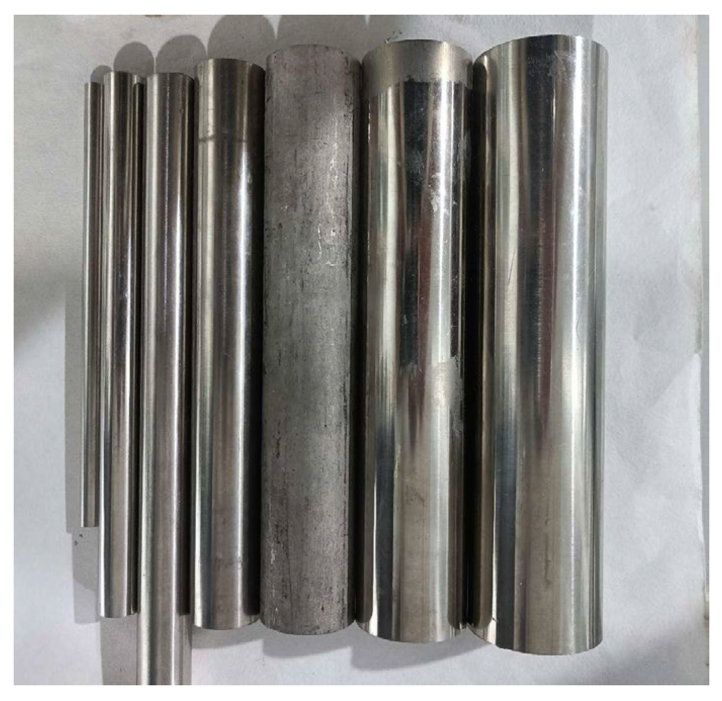
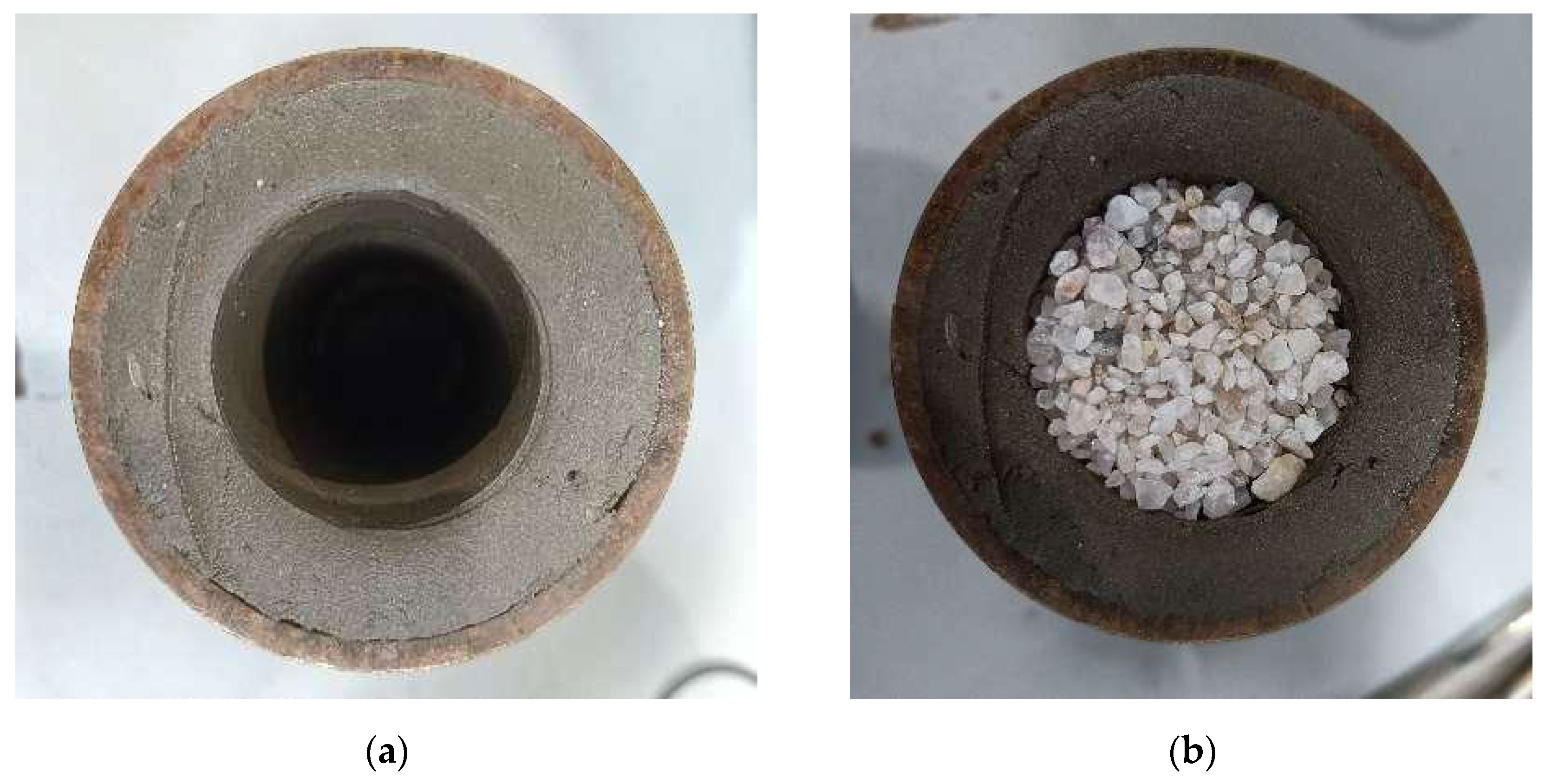
At the same time, to ensure that the triaxial shear soft soil sample is not destroyed, and that the replacement pile formed in the sample is a straight cylinder with the same diameter, so as to ensure that the calculation of the dynamic consolidation displacement rate only takes the plane area as the control variable, and the replacement operation of the sample gravel pile is simplified: First, the hollow tube in Figure 2 (the outer diameter is 8 mm, 14 mm, 18 mm, 24 mm, 36 mm, and 42.5 mm from left to right) is used to reserve replacement space in the sample in advance, as shown in Figure 3a, and the outer surface of the hollow steel pipe is evenly coated with Vaseline™. To ensure that the replacement space is reserved and the hollow tube is removed, the adhesion and interaction between the hollow tube and the surrounding soil can be minimized, and the test results are avoided due to excessive friction between the hollow tube and the surrounding soil. After the hollow tube is removed, the replacement of the gravel filler is completed once, the filler is placed until it is flush with the top surface, and the light pressure and vibration compact it. If the height of the filler drops, it can be supplemented.
In actual dynamic compaction, repeated dynamic compaction makes the gravel compact the surrounding soft soil, and the pressure is transferred from the gravel pile to the adjacent soft soil, but the resulting gravel pile is usually irregular in shape. In this experiment, the packing is only compacted by light pressure and vibration at the end to ensure the regular shape of the pile. Due to the small volume of the samples used in the test conducted in this research, the soft soil of the single pile sample and the multi-pile sample has already produced a certain degree of compaction due to the space reserved by the hollow pipe, and the distance between the piles of the multi-pile sample is relatively small, which further strengthens the compactive effect. Therefore, this research is designed to approximate the density and pressure transfer of the soft soil around the pile, and at the same time make regular-shaped gravel piles. To simulate the actual situation encountered in-situ, the rubble pile in the sample is in floating form, and no support is set at the bottom.

2.2. Test Scheme

As shown in Equation (1), the dynamic compaction replacement rate of gravel piles in the current standard is the ratio of the surface section area of the gravel pile foundation to the plane area of foundation.
m = A p A
where m is the displacement rate, Ap represents the surface cross-sectional area of the crushed stone pile foundation, and A is the plane area of the foundation.
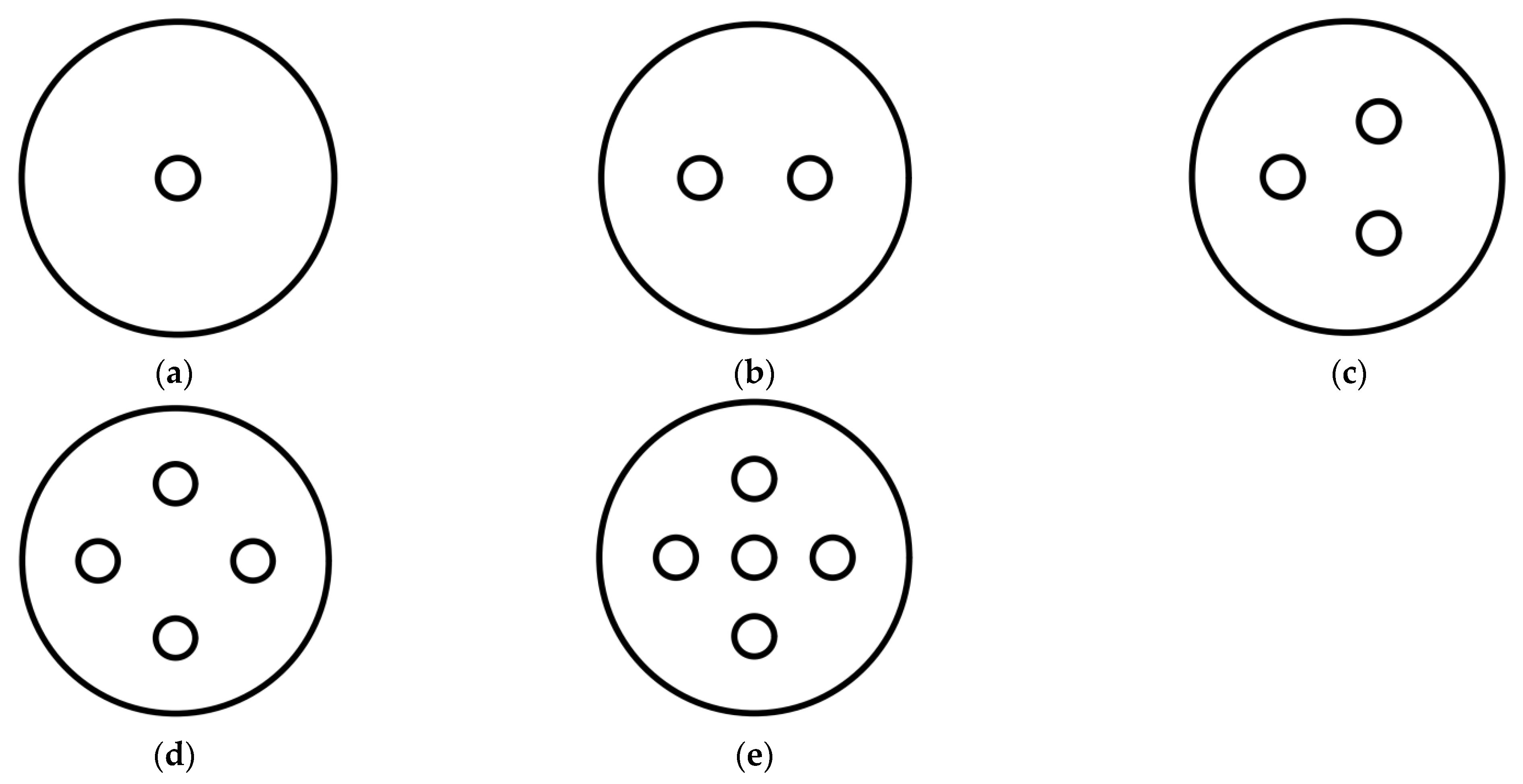
A single number of piles with different pile diameters and a single pile diameter with different numbers of piles are two ways to change the displacement rate of dynamic compaction. It is reflected in the test scheme, that is, the undrained shear test of the consolidation of silty clay with both single-pile replacement and multi-pile replacement. First, single-pile displacement is adopted, and the displacement rate is altered by changing the diameter of the displacement pile. Second, the diameter of a single pile is fixed, and the displacement rate is changed by adjusting the number of displacement piles. The influence of pile spacing in multi-pile displacement is not considered in this paper. CU tests under confining pressures of 50 kPa, 100 kPa, 200 kPa, and 300 kPa were conducted at each displacement rate to obtain stress–strain curves and effective stress paths, and then shear strength parameters, such as effective cohesion (c′) and effective internal friction angle (φ′), at different displacement rates were obtained. The specific test scheme is shown in Table 2 and Figure 4.

3. Test Results and Analysis

3.1. The Stress–Strain Relationship of Samples

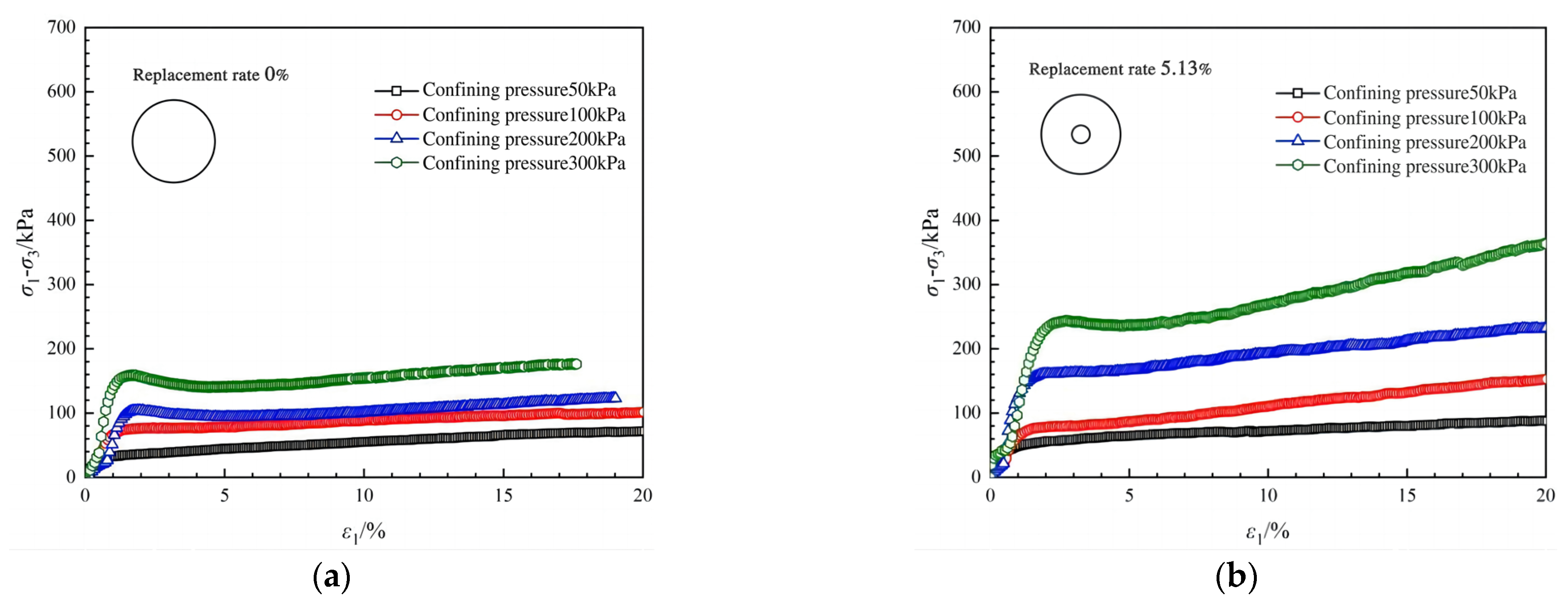
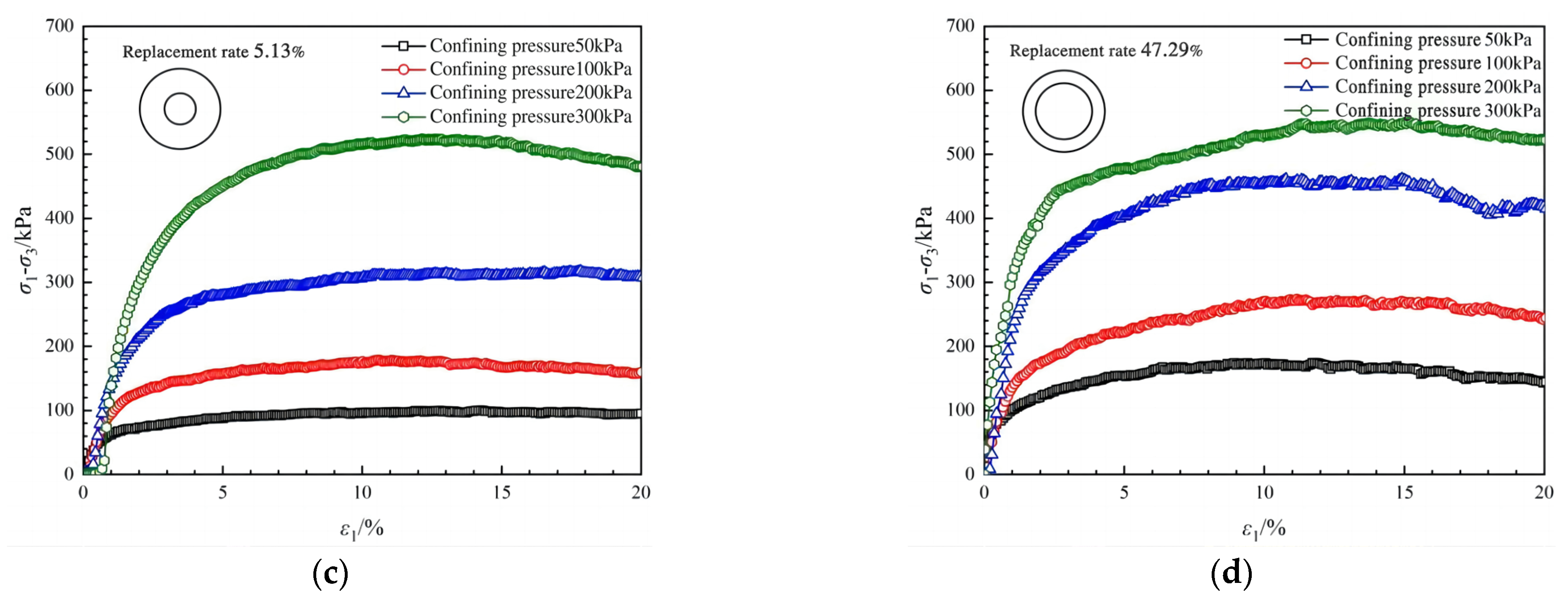
The representative results of Groups a, c, e, g, h, I, and k in the replacement test were selected for stress–strain analysis. Here, a, c, e, and g are single-pile replacement test groups. The stress–strain curves of the samples in the single-pile replacement test are shown in Figure 5.
The pure clay samples showed a strain hardening phenomenon: with the increase of strain under the confining pressures of 50 kPa and 100 kPa, it was noted that the stress increases rapidly at first and slowly thereafter. Under the confining pressures of 200 kPa and 300 kPa, the stress–strain relationship, as a whole, presents strain hardening, but the curve has extreme points, and the principal stress difference first decreases briefly and then augments slowly after a rapid increment. This phenomenon indicates that the yield surface in the stress space shrinks briefly during the process of expansion.
When the replacement rate is 5.13%, the stress–strain relationship of the sample is similar to that of the pure clay sample. Under low confining pressures (50 kPa, 100 kPa), the principal stress difference is close to that of pure clay samples, while under high confining pressures (200 kPa, 300 kPa), the principal stress difference is significantly increased. The results show that dynamic consolidation can improve the shear strength of soft soil, but the clay-like properties of the sample remain dominant at this displacement rate.
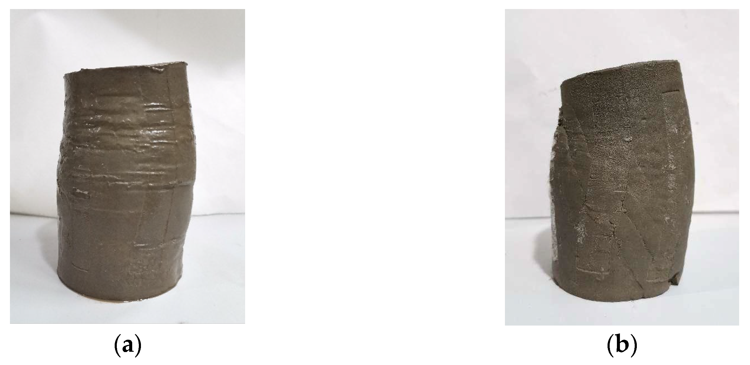
When the replacement rate increases to 15.08%, in addition to the further increment of the principal stress difference, the sample begins to show a strain softening phenomenon: with the increase of strain, the stress increase reaches a peak and begins to decline slowly, and the sample gradually changes from cohesive behavior to granular behavior. The samples of Group e with a replacement rate of 15.08% show a tendency to strain softening under confining pressures of 50 kPa, 100 kPa, and 200 kPa, but the strain softening is not significant. Combined with the failure state of the samples as shown in Figure 6a, the samples present slight dilatancy failure. Under the confining pressure of 300 kPa, the stress–strain relationship shows strain softening, and obvious shear bands appear in the sample (Figure 6b).
The sample exhibiting a swelling ratio of 47.29% demonstrates a transient deviation in the stress–strain curve at the conclusion of the test conducted under a confining pressure of 200 kPa; however, it displays plastic softening behavior at other confining pressures, suggesting that soil characteristics are the predominant factor influencing its response. Notably, the curve does not exhibit a pronounced drop, indicating that the cohesive properties continue to exert an influence.
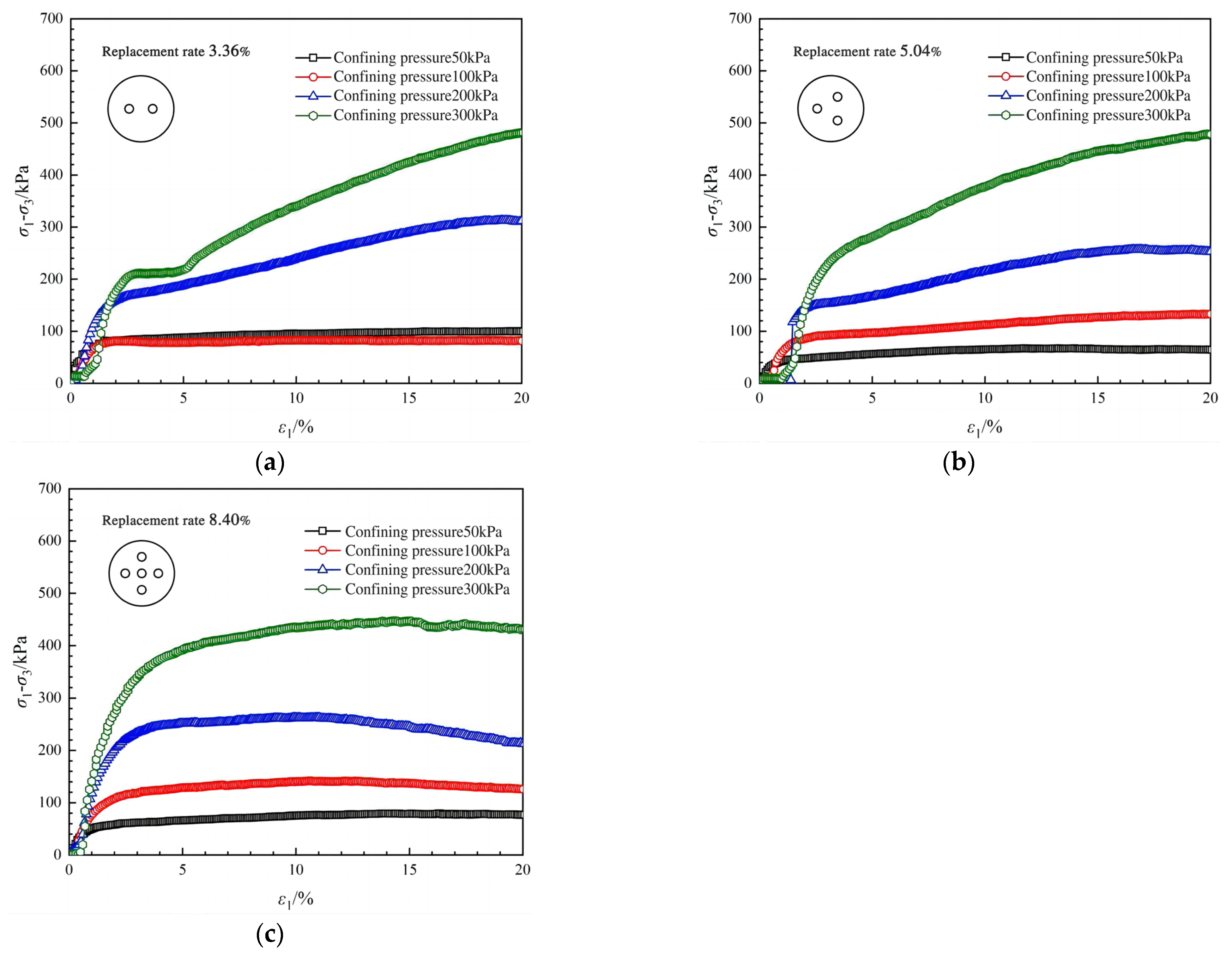
Groups h, i, and k are designated for the multi-pile replacement tests, and the stress–strain curve for the samples involved in these tests is illustrated in Figure 7.
As illustrated in Figure 7, at the low confining pressure of 50 kPa, an increment of the replacement rate does not lead to a significant enhancement in the principal stress difference. This suggests that, within the tested range of replacement rates and under low confining pressure conditions, the reinforcing effect of the sample is minimal; consequently, changes in the replacement rate do not substantially enhance the shear strength of the clay.
The sample with a replacement rate of 3.36% demonstrates a notable increase in the principal stress difference under confining pressures of 200 kPa and 300 kPa, surpassing the single-pile replacement rate of 5.13%; the replacement rate grows continuously, reaching 8.40%. Notably, the principal stress difference is significantly enhanced under confining pressures of 100 kPa, 200 kPa, and 300 kPa, surpassing the single-pile replacement rate of 8.48% and approaching that of 15.08%. It can be seen that augmenting the number of displacement piles enhances the displacement rate, and under this methodology, the improvement in the shear strength of clayey silty soil at a consistent displacement rate is markedly superior to that achieved by merely increasing the cross-sectional area of individual piles.

3.2. Evaluation of Shear Strength Parameters in Experimental Samples

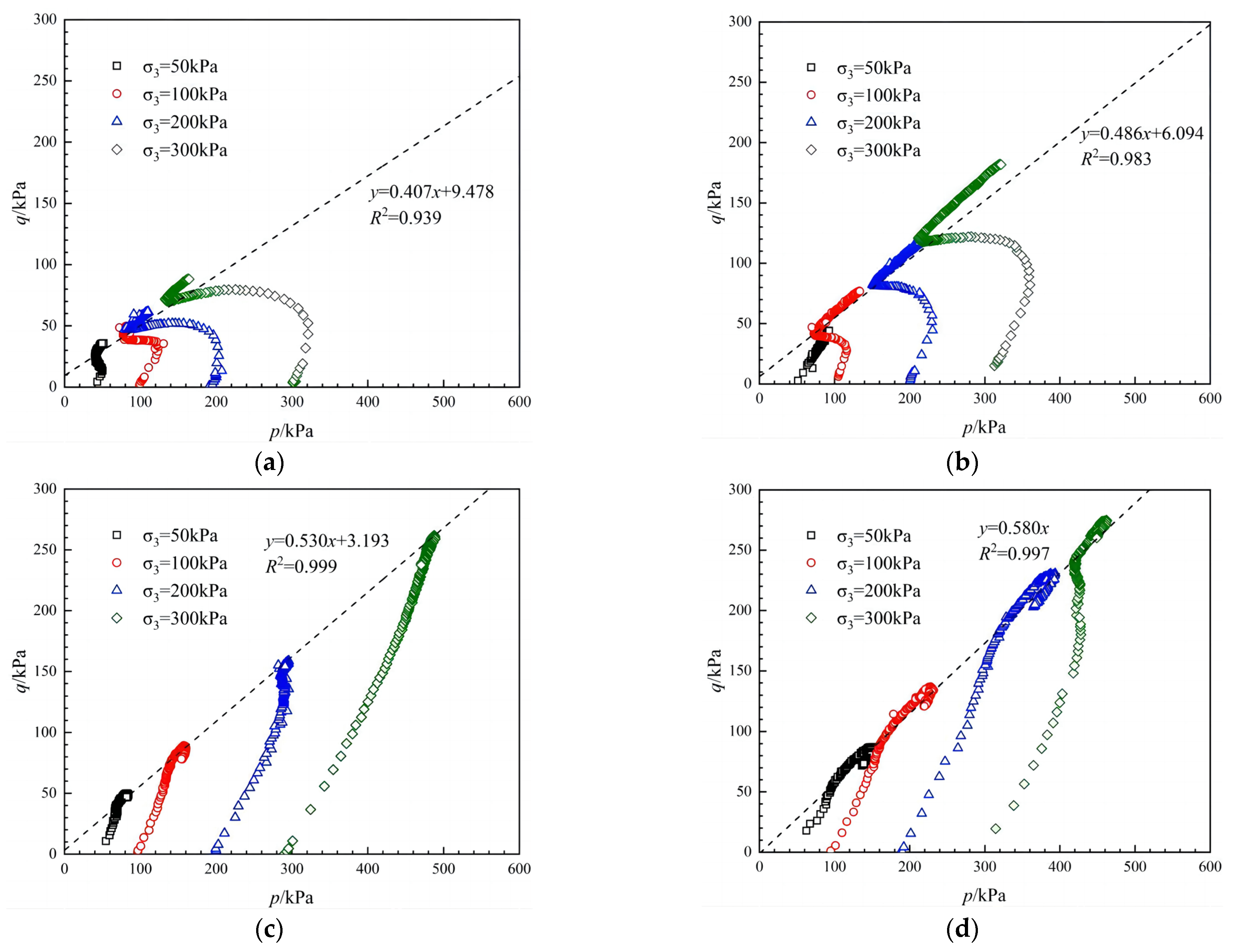
The effective stress path curve was drawn by plotting q = (σ1σ3)/2 on the vertical axis and p = (σ1 + σ3)/2 on the horizontal axis, as illustrated in Figure 8.
In the presence of pure clay or a low replacement ratio, the effective stress paths under varying confining pressures display a pronounced slanted “S” shape; as the substitution rate escalates, the curve progressively approaches a plateau; as the substitution rate rises to 15.08%, the effective stress path exhibits a quasi-linear increase, although a distinct kink remains visible at the end of the curve. The effective stress paths of multi-pile replacement test samples show similarities to those of single-pile replacement samples; however, the replacement rate for these samples is constrained, preventing the acquisition of the stress–strain relationship and effective stress path at higher replacement rates.
The inflection point of the effective stress path corresponds to the failure point of the sample during the shearing process. As the replacement rate ramps up, the axial strain at which sample failure occurs also increases; furthermore, a higher resistance to failure in clayey silt is correlated with an increment of its shear strength.

4. Effects of the Single-Pile Displacement Rate and Number of Piles on Shear Strength Parameters of Composite Soil

The effective cohesion (c′) and the effective internal friction angle (φ′) are deduced from the curve illustrating the effective stress path as follows:
c = b cos φ
ϕ = arcsin a
where, a is the slope of the fitting line of the failure point of the stress path curve, and b is the longitudinal intercept (kPa) of the regression line of the failure point of the stress path.
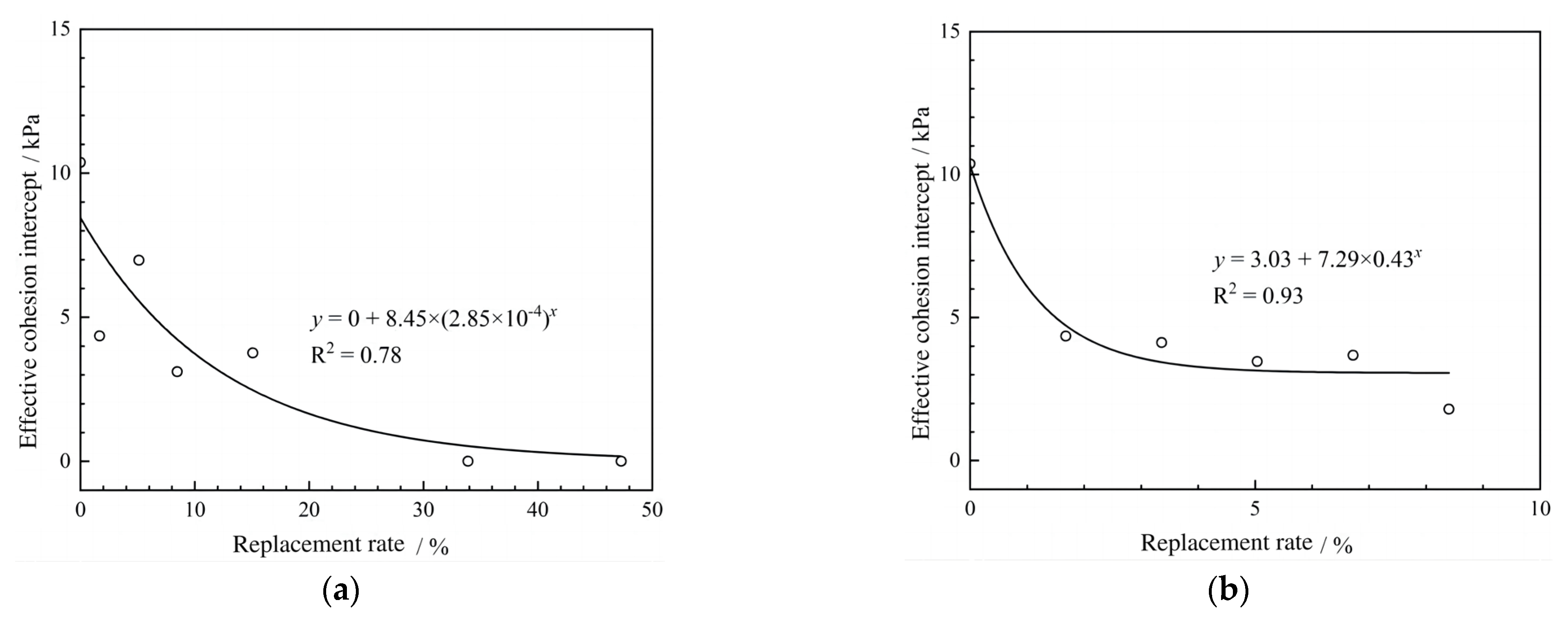
According to the curve of the change between the effective cohesion of composite soil and the displacement rate shown in Figure 9, the fitting equation of the effective cohesion of the consolidated undrained shear strength of composite soil is as follows:
c c u , c = α 1 β 1 ε 1 m
where m is the displacement rate; α1, β1, and ε1 represent the fitting parameters; α 1 β 1 ε 1 c c u , g gives the effective cohesion of the undrained shear strength of the consolidation of the replacement filler; α 1 β 1 c c u , s c represents the effective cohesion of the undrained shear strength of the consolidation of the soft clay.
As shown in Figure 9, the effective cohesion of silty clay drops with the increase in the displacement rate when the number of piles is different and the number of piles of a single diameter is different. When the displacement rate is exceeded, the effective cohesion reduces to a certain value and tends toward a constant, while no longer declining with the increase of displacement rate. In Figure 9b, the absolute slope of the curve with a single pile diameter and different numbers of piles is larger than that with a single number of piles and different pile diameters, the cohesion decreases faster, and the displacement rate required to reach the constant value is lower.
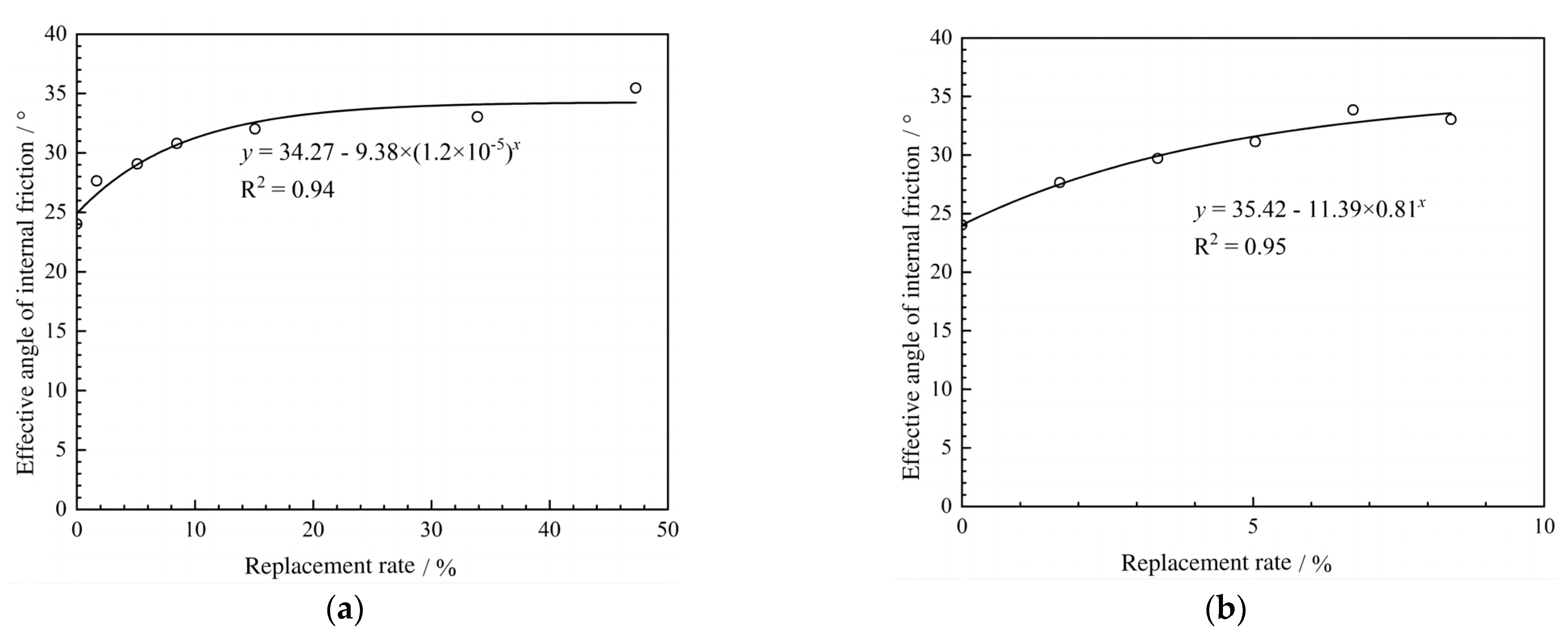
According to the relationship between the effective internal friction angle and replacement rate of composite soil as shown in Figure 10, the fitting equation of effective internal friction angle of consolidated undrained shear strength of composite soil is as follows:
φ c u , c = α 2 β 2 ε 2 m
where: m is the replacement rate; α2, β2, and ε2 are the fitting parameters; α 2 β 2 ε 2 φ c u , g is the effective internal friction angle of the undrained shear strength of the consolidated packing; α 2 β 2 φ c u , s c is the effective internal friction angle of undrained shear strength after consolidation.
As shown in Figure 10, the effective internal friction angle of silty clay enlarges with the increasing displacement rate when the single number of piles varies with different pile diameters and the single number of piles varies with different pile diameters. When the displacement rate is about 25%, the fitted curve is almost horizontal and the internal friction angle tends to a certain stable value. As shown in Figure 10b, the change in the effective internal friction angle curve under the condition of single pile diameter and different numbers of piles is greater than that under the condition of a single number of piles and different pile diameters. Combined with the curve of effective cohesion and the curve illustrating the stress–strain relationship, it can be shown that the shear strength of silty clay is improved with the increment of displacement rate. At the same displacement rate, the shear strength of silty clay is enhanced more significantly using the method of multi-pile displacement when increasing the number of piles.
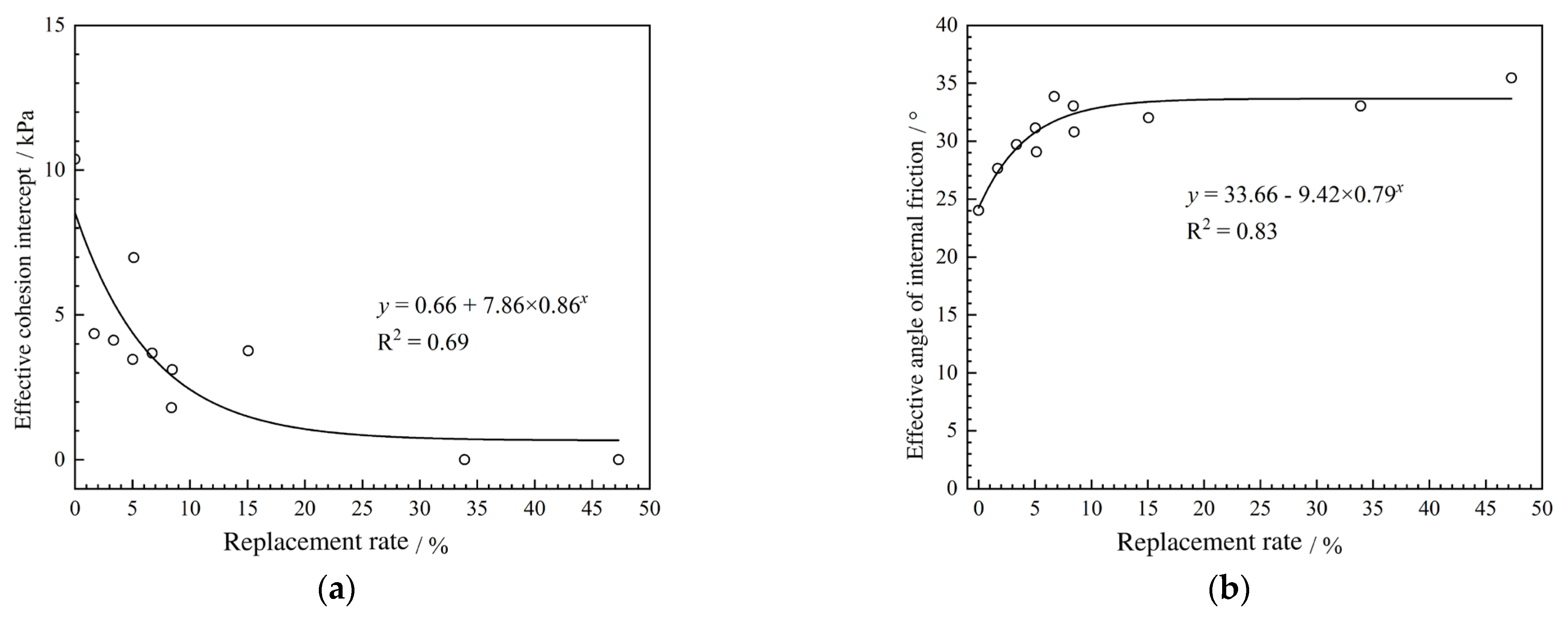
Under certain test conditions and based on certain sample properties, the test results of a single pile diameter with different numbers of piles and a single number of piles with different pile diameters were integrated, and the relationship between shear strength parameters and displacement rate was obtained uniformly, as shown in Figure 11.
Therefore, the experimental fitting equation of the shear strength parameters of the composite soil was established, as shown in Equations (6) and (7), expressing the changing relationship between the shear strength and the displacement rate of the composite soil.
The test method for composite soil cohesion:
c c = 0.66 + 7.86 × 0.86 m
The test method for the internal friction angle of composite soil:
ϕ c = 33.66 9.42 × 0.79 m
where: m is the replacement rate.

5. Analysis and Correction of Shear Strength Parameters

5.1. Correction of the Shear Strength Parameters

Based on the area replacement rate method, the general expressions for the comprehensive strength parameters of composite soil are given by Equations (8) and (9). The formulae show that the composite strength parameters of a crushed stone pile and the surrounding silty clay are determined according to the test strength under the same conditions, multiplied by the proportion of their respective areas, but its disadvantage is that it does not consider any pile–soil interaction.
The cohesion of composite soil by the area replacement rate method:
c c = m c g + ( 1 m ) c s c
The area replacement rate method of the composite soil internal friction angle:
tan φ c = m tan φ g + ( 1 m ) tan φ s c
where cg is the apparent cohesion of the gravel, csc is the cohesion of soft soil, φg is the internal friction angle of the gravel, and φsc is the internal friction angle of soft soil.
The lateral interaction between the pile and the soil of crushed stone pile composite foundation was studied by experiments, and the conclusion was drawn: Due to the dilatability of crushed stone materials, the radial stress on the pile–soil contact surface is higher than the confining pressure. The stress calculation of composite soil is not a simple combination of the displacement rate of stress by the area of different materials under the same test conditions, and factors such as the increase in the confining pressure on the pile after the lateral interaction between the pile and soil should be considered. Therefore, the confining pressure on a pile in composite soil has been modified, and the interaction coefficient ξ has been defined. The pile body in the composite soil mass is modified, and the formulae of comprehensive strength parameters of the modified composite soil mass are given by Equations (10) and (11).
The action coefficient method of composite soil cohesion:
C c = ( 1 m ) tan ( 45 ° + Φ s c 2 ) tan ( 45 ° + Φ s c 2 ) C s c
The active coefficient method for the internal friction angle of composite soil:
tan 2 ( 45 ° + Φ c 2 ) = ξ m tan 2 ( 45 ° + Φ g 2 ) + ( 1 m ) tan 2 ( 45 ° + Φ s c 2 )
where ξ is the interaction coefficient of pile and soil, and other symbols related to cohesion force and internal friction angle are distinguished from Equations (8) and (9), using upper case symbols, such as: Cg, Csc, Φg, and Φsc, in a manner congruent with Equations (8) and (9).
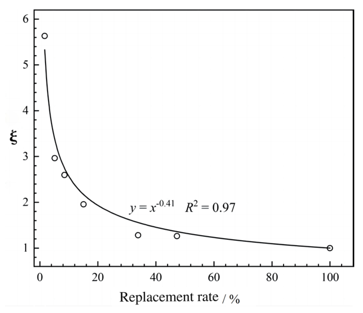
Based on the test data of the shear strength parameters of composite soil obtained from the single-pile replacement test, the pile–soil interaction coefficient was inverted through Equations (10) and (11), and the relationship between the pile–soil interaction coefficient and the replacement rate was obtained, as shown in Figure 12, where it may be seen that the pile–soil interaction coefficient is not a fixed value, but decreases with the increment of the displacement rate, matching the actual behavior of bulk piles: when the replacement rate is small, the coarse particles cannot form an independent skeleton, and the composite foundation can only act as a granular soil. Therefore, the pile–soil interaction coefficient is large. With the enlargement of the replacement rate, the difference in the pile–soil stress ratio increases, and the role of crushed stone piles becomes more apparent. Fine granular soil is not enough to fill the pores between coarse particles, and the pile–soil interaction diminishes. When the replacement rate is about 20%, the interaction effect drops sharply, showing that the pile–soil interaction coefficient reduces rapidly until the piles almost play a full role. The interaction coefficient of the pile and soil tends to be about 1. The fitting formula of the pile–soil interaction coefficient ξ is shown in Equation (12).
ξ = m 0.41
Combined with Equations (11) and (12), the corrected internal friction angle of a composite soil can be determined:
tan 2 ( 45 ° + Φ c 2 ) = m 0.59 tan 2 ( 45 ° + Φ g 2 ) + ( 1 m ) tan 2 ( 45 ° + Φ s c 2 )
The test results show that the shear strength parameters c and φ of gravel pile composite soil can be calculated using Equations (10) and (13) in the actual engineering of a coastal soft soil area with similar geological conditions.

5.2. Comparison and Application of Research Findings

It is necessary to explain that the above research results are the ideal results recorded in the laboratory, and the scale of the studied objects is small. If the actual situation in the field is taken into account, including the scale effect and the climate and hydrological conditions of the site, the research results will be changed. However, the author believes that the impact of scale effect or climate and hydrological conditions is small, and the research results will change slightly but the overall trend will remain quasi-stable.
In the field of soil improvement, by replacing the loose material, many researchers have conducted similar studies using methods such as triaxial shear tests [21], large direct shear tests [22], model tests [23], and numerical simulations combined with in-situ monitoring [24] to explore the improvement of soft soil by replacing it with loose materials. The loose materials used in these studies have expanded to include lime [2], coal ash [25], concrete core gravel [24], and polyethylene plastic waste particles [26] and other environmentally friendly materials. The conclusions obtained in this study are generally consistent with those of similar studies, including the fact that the shear strength of soft soil increases as the replacement rate is increased, and that the efficiency of increasing the shear strength of soft soil by using multi-pile replacement is significantly better than that of a single-pile replacement. Based on this, the study has fitted and summarized the formula for the correction of the shear strength parameters of soft soil improved by strong replacement, which is applicable to coastal soft soil.
By using this formula, Liu et al. [27] conducted an excavation model test of a coastal soft soil foundation pit on the basis of a pile envelope structure replaced by dynamic compaction to analyze the deformation of a foundation pit under different displacement rates and different slope angles and determine the shear strength parameters of the displacement pile envelope structure. Furthermore, they established the finite element numerical model of an excavation model test of the coastal soft soil foundation pit. The validity of the modified formula of shear strength parameters was verified by comparison with the experimental results, which provides a basis for the stability evaluation of the displacement pile envelope.
In the present work, the shear strength parameters of the displacement pile envelope were determined using the modified formula of the shear strength parameters, and a full-scale excavation model of coastal soft soil foundation pit was established using the pile–soil coupling numerical model, whereby the deformation and stability of the foundation pit during excavation under different displacement rates and slope rates were numerically simulated [28]. At the same time, the different layouts of dynamic consolidation pier and the supporting technology of a dynamic consolidation pier combined with steel sheet piles were simulated numerically: the simulated results can verify the validity of the correction formula for shear strength parameters. Based thereon, the following measures were proposed to improve the stability of the retaining structure of displacement piles for a coastal soft soil foundation pit:
(1) When the slope rate of the foundation pit is constant, properly increasing the dynamic consolidation displacement rate can enhance the stability of the enclosure structure;
(2) When the displacement rate of dynamic compaction is constant, the proper cutting and lowering of the slope can increase the stability of the enclosure structure;
(3) The plum blossom layout of the pier has almost no effect on the stability of the retaining structure, so the layout of the replacement pier can be ignored in strengthening the retaining structure of the foundation pit;
(4) The soft soil can be strengthened by displacement and then steel sheet pile is set for vertical excavation, which can improve the stability of the envelope structure, save excavation space, and reduce the amount of earthwork.
In addition, in view of the limitations of the triaxial test itself and the simplified influence of many complex factors in the consolidated undrained shear test adopted in this study, the authors intend to combine the research results and propose future steps for further deepening the aforementioned research:
(1) Considering the small scale of the triaxial test, the subsequent model test and larger scale field test will be conducted to estimate the effect of scale effect on the change of the shear strength of coastal soft soil with the replacement rate;
(2) The influences of climatic and hydrological conditions on the change of the shear strength of coastal soft soil with the replacement rate were studied by changing parameters, such as the water content of the soft soil in model tests;
(3) The effect of the displacement rate on the shear strength of coastal soft soil is the chosen research object; subsequent model tests and numerical simulations will be used to assess the effects of other key parameters pertaining to a displacement pile, such as pile material and particle size, permeability, compaction strength, and dynamic compaction duration, on the shear strength of coastal soft soil. According to this research, the variation in the shear strength of coastal soft soil under different displacement pile parameters was studied.

6. Conclusions

Through this research, the following main conclusions can be obtained:
Based on the CU test of coastal soft soil with different dynamic displacement rates, the stress–strain relationship and effective stress path of single-pile displacement and multi-pile displacement composite soil under different confining pressure conditions were determined, and the influences of different single-pile displacement rates and different numbers of piles on the shear strength of coastal composite soil were studied. A modified formula for the shear strength of coastal composite soil considering pile–soil interaction was established. It is found that the pile–soil interaction coefficient declines as a power function with the increment of displacement rate.
For a single pile diameter with different numbers of piles, the effective cohesion decreases from 10.4 kPa to 1.8 kPa as the displacement rate elevates, and the effective internal friction angle of silty clay enlarges with the increment of displacement rate, from 24.0° to 33.0°. As the displacement rate ramps up, the effective cohesion reduces from 10.4 kPa to 0, and the effective internal friction angle enlarges with the increase of displacement rate, from 24.0° to 35.0°.
Under the condition of a relatively small displacement rate and relatively good properties of soft soil, the displacement method of multi-pile displacement with the same displacement rate has a more significant enhancement effect on the shear strength of coastal soft soil.

Author Contributions

Conceptualization, K.H., Y.S., and M.Z.; methodology, M.Z.; software, M.Z.; validation, K.H. and Y.S.; formal analysis, Y.S. and L.S.; investigation, X.C., J.W., and J.L.; resources, X.C., A.J., and J.W.; data curation, Y.S. and L.S.; writing—original draft preparation, Y.S.; writing—review and editing, K.H.; visualization, Y.S.; supervision, K.H. and A.J.; project administration, K.H. and A.J.; funding acquisition, K.H. and A.J. All authors have read and agreed to the published version of the manuscript.

Funding

This research was funded by Key Project of Natural Science Foundation of Shandong Province, grant number: ZR2020KE004, funder: Natural Science Foundation of Shandong Province.

Data Availability Statement

The data presented in this study are available on request from the corresponding author. The data are not publicly available due to funding project confidentiality requirements.

Conflicts of Interest

Authors Xiaoyang Chen, Anliang Jiao, Jingjiang Wu and Jingkun Li were employed by the company Communications Construction Company of CSCEC 7th Division Corp. Ltd. The remaining authors declare that the research was conducted in the absence of any commercial or financial relationships that could be construed as a potential conflict of interest.

References

  1. Yan, Z.L.; Chen, X.L.; Gao, M.T.; Li, T. Experimental study on dynamic characteristics of muddy soil in Qingdao Jiaozhou Bay. World Earthq. Eng. 2014, 30, 261–268. [Google Scholar]
  2. Sakr, M.; El-Sawwaf, M.; Azzam, W.; El-Disouky, E. Improvement of shear strength and compressibility of soft clay stabilized with lime columns. Innov. Infrastruct. Solut. 2021, 6, 133. [Google Scholar] [CrossRef]
  3. Al-Khafaji, K.R.; Fattah, M.Y.; Al-Recaby, M.K. Assessment of creep improvement of organic soil improved by stone columns. Geomech. Eng. 2024, 38, 191–203. [Google Scholar]
  4. Feng, S.J.; Tan, K.; Shui, W.H. Dynamic Compaction of Ultra-High Energy in Combination with Ground Replacement in Coastal Reclamation Areas. Mar. Georesour. Geotechnol. 2014, 33, 109–121. [Google Scholar] [CrossRef]
  5. Piotr, K.; Sławomir, K.; Jerzy, S. Soil Overconsolidation Changes Caused by Dynamic Replacement. IOP Conf. Ser. Mater. Sci. Eng. 2017, 245, 022062. [Google Scholar] [CrossRef]
  6. Lee, K.H.; Kim, S.K.; Yea, G.G.; Kim, H.Y. Assessment of Dynamic Characteristics for Compaction Piles with Geophysical Logging in Soft Ground. Mar. Georesour. Geotechnol. 2013, 32, 62–75. [Google Scholar] [CrossRef]
  7. Ammari, K.A.; Clarke, B.G. Effect of Vibro Stone-Column Installation on the Performance of Reinforced Soil. J. Geotech. Geoenviron. Eng. 2018, 144, 04018056. [Google Scholar] [CrossRef]
  8. Tarawneh, B.; Al Bodour, W.; Shatnawi, A.; Al Ajmi, K. Field evaluation and behavior of the soil improved using dynamic replacement. Case Stud. Constr. Mater. 2019, 10, e00214. [Google Scholar] [CrossRef]
  9. Cheng, X.S.; Jing, W. Calculation models and stability of composite foundation treated with compaction piles. Geomech. Eng. 2017, 13, 929–946. [Google Scholar]
  10. Gou, D.Z.; Li, Y.Y.; An, X.Z.; Yang, R. DEM modelling of particle fragmentation during compaction of particles. Powder Technol. 2022, 398, 117073. [Google Scholar] [CrossRef]
  11. Zhou, Y.D.; Zheng, Q.D.; Guo, S.J. Nonlinear consolidation model of composie foundation with partially penetrated stone column. Comput. Geotech. 2023, 161, 105621. [Google Scholar]
  12. Chen, P.; Lyu, W.; Liang, X.; Deng, J.; Li, C.; Yuan, Y. Multi-Factor Influence Analysis on the Liquefaction Mitigation of Stone Columns Composite Foundation. Appl. Sci. 2022, 12, 7308. [Google Scholar] [CrossRef]
  13. Etezad, M.; Hanna, A.M.; Ayadat, T. Bearing Capacity of a Group of Stone Columns in Soft Soil. Int. J. Geomech. 2015, 15, 04014043. [Google Scholar] [CrossRef]
  14. Mohamed, M.K.; Sakr, M.A.; Azzam, W.R. Geotechnical behavior of encased stone columns in soft clay soil. Innov. Infrastruct. Solut. 2023, 8, 80. [Google Scholar] [CrossRef]
  15. Guo, W.; Wang, X.; Ren, Y.X. Experimental study on underwater rammed stone column. Appl. Ocean Res. 2023, 140, 103740. [Google Scholar] [CrossRef]
  16. Wang, X.; Guo, W.; Ren, Y.X.; Xu, H.; Kang, Y.-F. Installation behavior of an underwater rammed stone column in clay. Acta Geotech. 2024, 19, 3213–3228. [Google Scholar] [CrossRef]
  17. Sakr, M.A.; Nazir, A.K.; Azzam, W.R.; Ali, N.O. Improving the Soft Clay using Seashell and Eggshell for Road Construction. J. Eng. Res. 2022, 6, 8. [Google Scholar]
  18. Sakr, M.A.; Nazir, A.K.; Azzam, W.R.; Ali, N.O. Soft clay improvement using eggshell powder as a sustainable material. Int. J. Geotech. Eng. 2023, 18, 377–391. [Google Scholar] [CrossRef]
  19. Zhang, H.N.; Guan, Y.; Dou, Y.G.; Wang, Q.; Xu, R.; Qin, S.; Wang, R.; Xia, W. Clay mineral assemblages and provenance in the surface sediment of Jiaozhou Bay. Mar. Geol. Front. 2023, 39, 20–28. [Google Scholar]
  20. Zhuang, H.H.; Xu, S.H.; Gao, M.S.; Hou, G.H.; Bai, E.T.; Huang, X.Y. Grain size characteristics of surface sediments in Jiaozhou Bay and their depositional environments. Mar. Geol. Front. 2018, 34, 24–31. [Google Scholar]
  21. Frikha, W.; Tounekti, F.; Kaffel, W.; Bouassida, M. Experimental study for the mechanical characterization of Tunis soft soil reinforced by a group of sand columns. Soils Found. 2015, 55, 181–191. [Google Scholar] [CrossRef]
  22. Nazariafshar, J.; Aslani, M. Effect of Stress Concentration Ratio on Shear Strength of Soft Soils Improved with Stone Columns. Iran J. Sci. Technol. Trans. Civ. Eng. 2021, 45, 315–334. [Google Scholar] [CrossRef]
  23. Ney, M.; Rackwitz, F. Baugrundverbesserung mit Sandsäulen in weichen organischen Böden. Bautechnik 2020, 97, 615–625. [Google Scholar] [CrossRef]
  24. Chen, S.Y.; Guan, Y.F.; Dai, J.Q. Field Experimental and Numerical Studies on Performance of Concrete–Cored Gravel Column-Supported Embankments. Int. J. Geomech. 2023, 23, 04023026. [Google Scholar] [CrossRef]
  25. Zaini, M.S.I.; Hasan, M.; Jusoh, W.N.B.W. Utilization of bottom ash waste as a granular column to enhance the lateral load capacity of soft kaolin clay soil. Environ. Sci. Pollut. Res. 2023. [Google Scholar] [CrossRef]
  26. Zaini, M.S.I.; Hasan, M.; Almuaythir, S. Experimental study on the use of polyoxymethylene plastic waste as a granular column to improve the strength of soft clay soil. Sci. Rep. 2024, 14, 22558. [Google Scholar] [CrossRef]
  27. Liu, Q.; Gao, L.Q.; Zhao, M.; Li, X.C.; Peng, Z.H. Study on the influence of dynamic compaction replacement on the stability of soft soil foundation pit slope excavation. Yangtze River 2024, 55, 226–233. [Google Scholar]
  28. Zhao, M. The Reinforcement Mechanism and Stability Evaluation of The Dynamic Replacement Method on Marine Soft Soil Foundation. Qingdao Univ. Technol. 2022, 115–130. [Google Scholar]
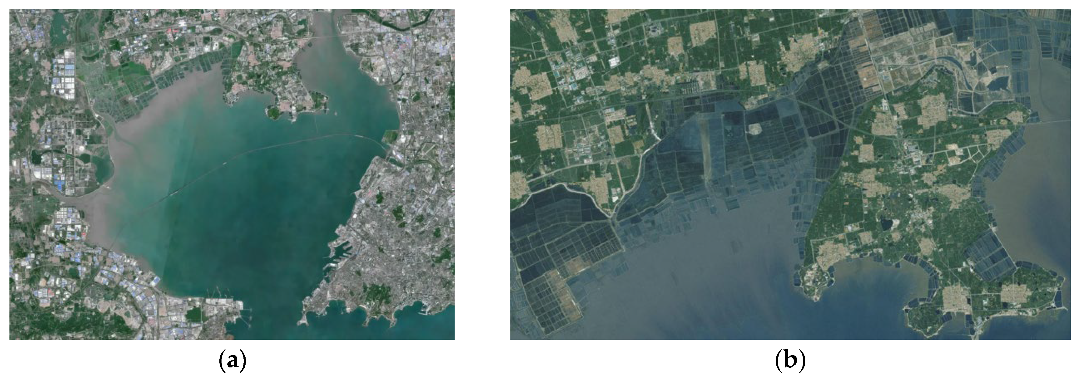
Figure 1. The map of Jiaozhou Bay. (a) Satellite map of Jiaozhou Bay. (b) Satellite map of sampling site.
Buildings 14 03491 g001
Figure 2. The replacement hollow tube.
Buildings 14 03491 g002
Figure 3. Soft soil sample replacing a gravel pile. (a) Before replacement. (b) After replacement.
Buildings 14 03491 g003
Figure 4. Pile position distribution map of multi-pile displacements. (a) The replacement rate of Group b is 1.68%. (b) The replacement rate of Group h is 3.36%. (c) The replacement rate of Group I is 5.04%. (d) The replacement rate of Group j is 6.72%. (e) The replacement rate of Group k is 8.40%.
Buildings 14 03491 g004
Figure 5. The stress–strain relationship of single-pile replacement samples. (a) The replacement rate of Group a is 0%. (b) The replacement rate of Group c is 5.13%. (c) The replacement rate of Group e is 15.08%. (d) The replacement rate of Group e is 47.29%.
Buildings 14 03491 g005aBuildings 14 03491 g005b
Figure 6. Failure states of samples in Group e. (a) σ3 = 50 kPa. (b) σ3 = 300 kPa.
Buildings 14 03491 g006
Figure 7. The stress–strain relationship of multi-pile replacement samples. (a) The replacement rate of Group h is 3.36%. (b) The replacement rate of Group i is 5.04%. (c) The replacement rate of Group k is 8.40%.
Buildings 14 03491 g007
Figure 8. The effective stress path for a single-pile replacement sample. (a) The replacement rate of Group a is 0%. (b) The replacement rate of Group c is 5.13%. (c) The replacement rate of Group e is 15.08%. (d) The replacement rate of Group g is 47.29%.
Buildings 14 03491 g008
Figure 9. The relationship between the effective cohesion and displacement rate. (a) Single number of piles; different pile diameters. (b) Single pile diameter; different numbers of piles.
Buildings 14 03491 g009
Figure 10. The relationship between the effective internal friction angle and displacement rate. (a) Single number of piles; different pile diameters. (b) Single pile diameter; different numbers of piles.
Buildings 14 03491 g010
Figure 11. Comprehensive analysis of shear strength parameters. (a) The relationship between the effective cohesion and displacement rate. (b) The relationship between the effective internal friction angle and displacement rate.
Buildings 14 03491 g011
Figure 12. The relationship between the pile–soil interaction coefficient ξ and displacement rate.
Buildings 14 03491 g012
Table 1. Basic physico-mechanical properties of silty clay.
Soil SampleMoisture Content/% Density/g·cm−3 Specific GravityVoid RatioSaturation Ratio/%Liquid Limit/%Plastic Limit/%Internal Friction Angle/°Cohesion/kPa
Silty clay351.912.752.4996.830.316.44.63.6
Table 2. Testing program.
NumberDisplacement Pile Diameter/mmDisplacement Pile NumberDisplacement Rate/%
a000
b811.68
c1415.13
d1818.48
e24115.08
f36133.90
g42.5147.29
h823.36
i835.04
j846.72
k858.40
Disclaimer/Publisher’s Note: The statements, opinions and data contained in all publications are solely those of the individual author(s) and contributor(s) and not of MDPI and/or the editor(s). MDPI and/or the editor(s) disclaim responsibility for any injury to people or property resulting from any ideas, methods, instructions or products referred to in the content.