Abstract
The majority of the existing calculation methods for determining the ultimate bearing capacity of steel-pipe piles using Chinese criteria are designed for piles with diameters smaller than 2 m. To investigate the bearing capacity of flexible steel-pipe piles with diameters larger than 2 m under combined loading conditions, reveal nonlinear interactions between vertical and horizontal loads, and propose bearing capacity envelopes, in this paper, a numerical method was used to study the bearing capacity of a flexible pile with a diameter of 2.8 m and an embedment length of 72 m under vertical and horizontal loading conditions. First, a numerical model was developed and calibrated using field test results. Then, the effects of vertical pressure on horizontal capacity and lateral force on vertical capacity and uplift capacity of the pile were analyzed. The results indicate that vertical pressure at the top of the pile can nonlinearly reduce its horizontal capacity, but this pressure initially has a slight positive effect on the horizontal bearing capacity before causing a rapid decrease. Conversely, horizontal force negatively impacts both the compressive and uplift bearing capacities of the pile. Finally, depending on the above results, bearing capacity envelopes for piles subjected to vertical and horizontal loads were proposed.
1. Introduction
In recent years, large-diameter flexible pile foundations (diameter larger than 2.0 m with typical flexible behavior) have been widely used in bridge construction, offshore wind power projects, and other engineering applications in China [,,]. However, the design standards for the ultimate vertical and horizontal bearing capacities of such foundations are still based on small-diameter piles [,,].
To address the above problem, systematic studies about the bearing capacities of large-diameter piles under complex loads have also been conducted. Gu et al. [] conducted laboratory model tests to explore the interactions between horizontal, vertical, and moment effects on concrete single piles with a diameter of 46 mm and a length of 2.0 m, and they also provided corresponding design recommendations for pile bodies. Liu [] studied the changes in the bearing capacity of single piles under horizontal and inclined loads in a single-layer soil with the application of PLAXIS 3D, and the value of m in the calculation methods for horizontal bearing capacity under combined loading conditions was studied. Li et al. [] have investigated the bearing capacity of steel-pipe piles under combined loading and moment by model tests. They identified the relationships between vertical, horizontal, and moment components at failure and proposed a combined load influence coefficient. The pile foundation diameter of 0.8~1.5 m and length of 15~50 m were selected by He et al. [] to investigate the ultimate uplift bearing capacity. The results indicated that the influence of pile diameter surpasses that of pile length. Chen et al. [] selected 50 test cases from a database in which the range of the cross-sectional area of piles is 226~500 m2 and proposed multiple artificial intelligence models for predicting the bearing capacity of piles. However, the test piles used in above studies had a relatively small diameter and did not reflect the characteristics of large-diameter piles. Chen et al. [] proposed a nonlinear interaction calculation model for a rigid cap spring beam–soil group pile foundation subjected to simultaneous horizontal and torsional loads. The model accounts for the coupling effects between different foundations. In the study, model tests of piles with a diameter of 114 mm and a length of 5.95 m were conducted, and the influences of the parameters were also studied. Zhuang et al. [] used numerical simulations to analyze the factors affecting the bearing capacity of single piles under lateral loads; various factors including pile diameter, soil stiffness, pile length, wall thickness, and cohesion were studied, and several recommendations for improving the horizontal bearing capacity of single piles were also proposed. Haiderali et al. [] used finite element analysis to investigate the horizontal bearing capacity of a single-pile foundation with a diameter of 3.8 m subjected to cyclic loads in clay. Pan et al. [] investigated the lateral bearing mechanism and internal force variations of an ultra-long steel-pipe pile with a diameter of 2.8 m through field tests and numerical simulations. Mu et al. [] considered the impact of vertical forces in a wedge-shaped model and revised the function of p–y curves. Previous studies indicate that the existing vertical pressure decreases the performance of the horizontal bearing capacity [,,], while the opposite opinion is that the existing vertical loads have positive effects on the performance, with the P-Δ effect being considered [,,,]. However, the previous studies do not provide a systematic analysis of the bearing capacity of flexible large-diameter piles under complex loading conditions.
This paper aims to solve the above problem by verifying the bearing characteristics of a typical pile foundation under such conditions. Using field test data from the study by Pan et al. [], numerical simulation models for a typical large-diameter flexible pile were validated. The research explored various combinations of horizontal and vertical loading patterns, and the novelty of this topic is to investigate the bearing capacity of large-diameter flexible steel-pipe piles under combined loading conditions. The study can reveal nonlinear interactions between vertical and horizontal loads and propose bearing capacity envelopes for such piles.
2. Numerical Simulation Method
2.1. Model Development and Parameter Selection
Based on the field test data from Pan et al. [] and Li et al. [], the test pile is a typical, long, flexible large-diameter pile with a diameter of 2.8 m and an embedment depth of 72 m. The relevant parameters are provided in Table 1 and Figure 1. The pile is primarily situated in a soil environment consisting of silty clay and silt, with the silty clay layer reaching a thickness of approximately 25 m. The distribution and parameters of the soil layers are detailed in Table 2.

Table 1.
Relative parameters of the pile.
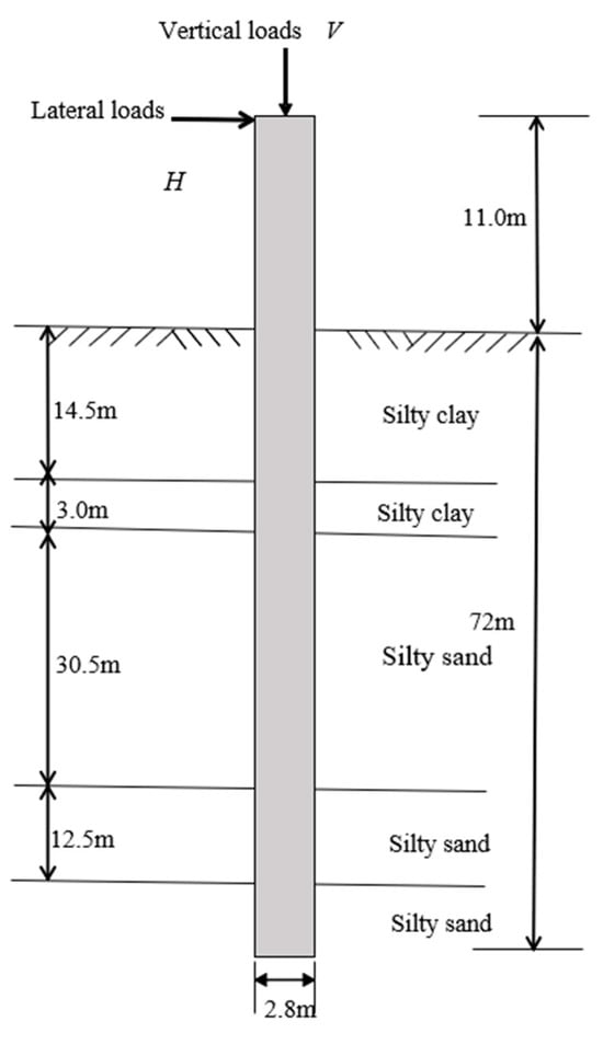
Figure 1.
Diagram of the tested pile.

Table 2.
Parameters of soil layers.
Engineering experience suggests that the soil core inside a large-diameter steel-pipe pile has a minimal impact on its horizontal bearing capacity []. Therefore, the soil surface inside the pile was kept flat with ground soil. In this study, a three-dimensional solid model was created by using ABAQUS. Because the loading process does not induce localized plastic deformation in the pile, an elastic model was used for the pile. The pile’s elastic modulus is Ep = 210 MPa, the Poisson’s ratio is 0.23, the wall thickness is t = 4.5 mm, and the embedment depth is Le = 72 m. The loading point of the field test pile is 11 m above the mudline.
To avoid boundary effects, the soil model was built as a cubic shape with the length (at x-directions) and width (at y-directions) being 1 times the pile length, and the height (at z-direction) 2 times the pile length. According to the geotechnical investigation, the main soil layers are silty clay and silty sand. Therefore, the soil layers were divided into six layers, and the Mohr–Coulomb model was used to simulate elastoplastic behavior of soil. The elastic moduli of the soil layers were set as the midpoint values recommended in the geotechnical report: Es1 = 91.3 MPa; Es2 = 155.3 MPa; Es3 = 155.3 MPa; Es4 =147.3 MPa; Es5 = 180 MPa; and Es6 = 250 MPa. The Poisson’s ratios are μ1 = 0.4; μ2 = μ3 = 0.37; μ4 = 0.35; μ5 = 0.33; and μ6 = 0.34. The friction angles and cohesions for silty soil and silt are listed in Table 1. The grid was designed to be as uniform as possible, with consistent mesh density at the pile–soil contact points. In this study, a face-to-face contact type was used, and the master–slave contact algorithm was chosen; the pile foundation surface with higher stiffness was regarded as the main control surface and the soil surface as the subordinate surface. The normal behavior of the contact surface was set as hard contact, and the tangential behavior model was described by the Mohr–Coulomb friction penalty function. The physical properties of the pile–soil contact surface were defined to be consistent with the soil. The coefficient of sliding friction is μ = tan (0.75φ′), where the value of φ′ at each soil layer was given in Table 2. The contact surface allows the existence of gaps and separations between the interacting surfaces. The constructed pile element model is shown in Figure 2a, and the grids are shown in Figure 2b. For the boundary conditions, the velocity of each element at the sides and bottom of the soil model is zero in the direction perpendicular to the boundaries.
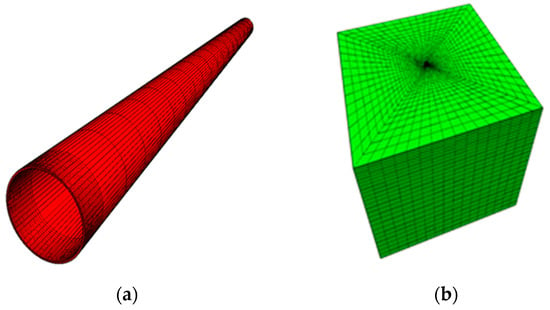
Figure 2.
Diagrams of the numerical simulation: (a) the pile and (b) the soil.
During the calculation process, initial geostatic equilibrium is first established. The soil at the location of the pile is removed; then, the pile is inserted, and equilibrium is re-established before proceeding with subsequent loading conditions. In the loading process, horizontal or vertical loads are defined as uniformly distributed loads applied at the top of the steel-pipe pile. The loading method involves staged loading to study the pile’s displacement and internal forces under horizontal or vertical loads. The results are then compared with field test data for validation.
2.2. Comparison and Validation of Simulation Results
To verify the accuracy of the numerical simulation results, as shown in Figure 3, displacement–load curves for vertical and horizontal loads from the numerical simulations were compared with the results from the test piles. Figure 3 indicates that the pile-top displacement–load curves fit well with the in situ test data, confirming that the numerical simulation model is reasonably accurate, and the results are reliable.
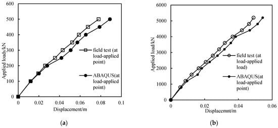
Figure 3.
Comparison of results between tests and simulations: (a) horizontal load–displacement curves and (b) vertical load–displacement curves.
It is worth noting that in Figure 3, the graphs constructed based on the results of field tests look more monotonous than those obtained based on the results of modeling in the ABAQUS environment. The reason is that the field tests are conducted in real-world environments, which often have inherent limitations and constraints. These can include environmental conditions, equipment limitations, and the variability of real-world data. As a result, the data collected may be more consistent and less variable, requiring a more simplified scientific model to describe.
2.3. Loading Strategies
In this section, as shown in Table 3, three loading strategies were designed.

Table 3.
Working conditions of simulations.
The horizontal bearing capacity of steel-pipe piles under existing vertical loads ranges from 1.0 MN to 5.0 MN. Initially, a constant vertical pressure load (1.0 MN, 2.0 MN, 3.0 MN, 4.0 MN, or 5.0 MN) is applied at the pile head. Once equilibrium is reached, the vertical pressure at the pile head is kept constant while incremental horizontal loads are applied from 0 kN until the pile reaches its ultimate bearing capacity. During this process, the vertical pressure remains unchanged.
The vertical compressive bearing capacity under existing horizontal forces ranges from 0.1 MN to 0.5 MN. Initially, a constant horizontal load is applied to the pile head. The horizontal load is 0.1 MN, 0.2 MN, 0.3 MN, 0.4 MN, or 0.5 MN. Once equilibrium is reached, this horizontal load is maintained while incremental vertical pressures are applied until the pile reaches its ultimate bearing capacity. This approach is used to study how different horizontal loads affect the vertical bearing capacity of the pile.
The pullout bearing capacity under existing horizontal forces ranges from 0.1 MN to 0.5 MN. Initially, a constant horizontal load is applied to the pile head. The horizontal load is 0.1 MN, 0.2 MN, 0.3 MN, 0.4 MN, or 0.5 MN. Once equilibrium is reached, this horizontal load is maintained while incremental vertical uplift forces are applied until the pile reaches its ultimate bearing capacity. This approach is used to study how different levels of horizontal load affect the vertical uplift bearing capacity of the pile.
3. Results and Discussion
3.1. The Impact of Existing Pile Head Pressure on Horizontal Bearing Characteristics
The pile head displacement–load curves are given in Figure 4. From the figure, the bearing capacity reflected by the horizontal displacement–load curve significantly decreases when vertical pressure is present. As the vertical pressure increases, the horizontal displacement at the pile head under the same horizontal load also increases. Notably, the influence of vertical pressure on the horizontal load–displacement curve is particularly pronounced when the vertical pressure increases from 1 MN to 2 MN and from 4 MN to 5 MN. In contrast, the influence is relatively less noticeable when the vertical pressure increases from 0 MN to 1 MN and from 2 MN to 4 MN. Furthermore, the horizontal bearing capacity of the pile at a vertical pressure of 3 MN is improved compared to the case with a vertical pressure of 2 MN. This means that, under these conditions, the effect of vertical load on horizontal load is not linear and exhibits a range where the impact is relatively small.
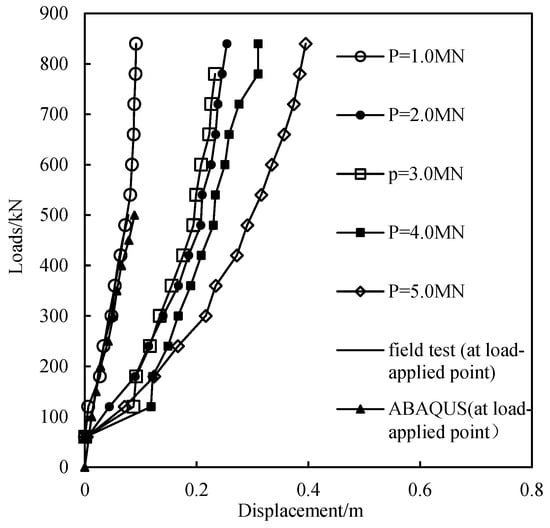
Figure 4.
The horizontal load–displacement curves of a pile at the mudline under different vertical pressures.
Figure 5 shows the variation of pile displacement with burial depth under different horizontal loads, with Figure 5a–c corresponding to vertical pressures of 3.0 MN, 4.0 MN, and 5.0 MN, respectively. Comparing these figures, it is evident that as vertical pressure increases, the horizontal displacement at the pile head under the same horizontal load increases significantly. Additionally, all figures exhibit a distinct inflection point, with the locations of these inflection points being approximately the same (around 30 m in depth), and the displacement at the pile tip is relatively small. Therefore, under horizontal loading, the deformation of the pile is clearly divided into two regions: the region above the inflection point and the region below the inflection point down to the pile tip. This indicates that vertical pressure has a significant effect on the horizontal bearing characteristics of the pile, with higher vertical bearing capacity resulting in a more pronounced impact on horizontal bearing characteristics.
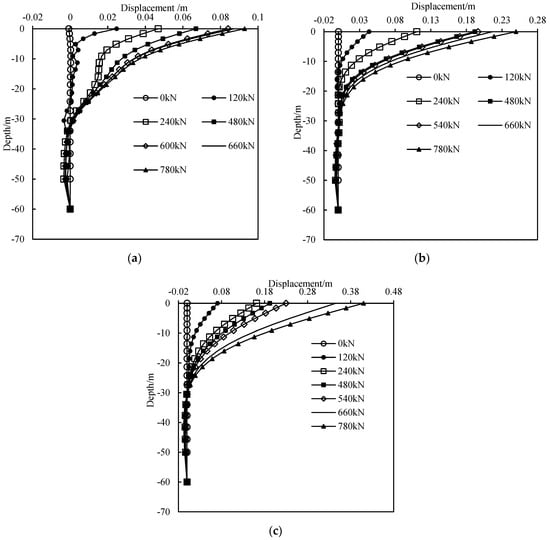
Figure 5.
The displacement of a pile along depth under different vertical pressures: (a) V = 1.0 MN, (b) V = 3.0 MN, and (c) V = 5.0 MN.
Figure 6 shows the bending moments under different levels of horizontal load for vertical pressures of 1 MN, 3 MN, and 5 MN. The data reveal that the maximum bending moment in the pile occurs approximately 10 m below the mudline. While the maximum value of the bending moment varies significantly with different horizontal loads, higher vertical pressures result in larger maximum bending moments. This indicates that vertical pressure markedly increases the bending moment in the pile without changing its distribution pattern along the length of the pile. Additionally, as vertical pressure increases, the rate of increase in the maximum bending moment diminishes, suggesting that higher vertical pressure reduces the extent of bending moment growth during horizontal loading.
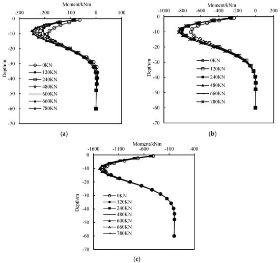
Figure 6.
The bending moment along depth under different vertical pressures: (a) V = 1.0 MN, (b) V = 3.0 MN, and (c) V = 5 MN.
In conclusion, it can be seen that the presence of vertical pressure reduces the horizontal bearing capacity of the pile foundation, but the effect is nonlinear. As the vertical pressure increases to a certain extent toward 10% of the ultimate vertical bearing capacity (Vult), the horizontal bearing capacity of the pile may actually improve, although this improvement diminishes very fast as the pressure continues to increase.
3.2. The Impact of Existing Horizontal Loads on Compressive Bearing Capacity
In this section, the impact of horizontal loads on the vertical compressive bearing capacity of piles is studied. Figure 7 shows the vertical displacement–load curves at the pile head under different horizontal loads. The figure includes a comparison between in situ tests and numerical simulations with H = 0 MN. It is evident that under different horizontal loads, the vertical load–displacement curves are generally consistent, indicating that horizontal loads have a limited effect on these curves in this study.
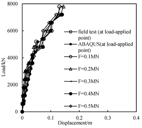
Figure 7.
The vertical load–settlement curves of a pile at mudline under different horizontal loads.
Conversely, the horizontal load–displacement curves are significantly influenced by vertical pressure, while vertical load–displacement curves are only marginally affected by horizontal loads. This phenomenon may be attributed to the larger differences in vertical pressure between adjacent levels (1.0 MN) compared to the smaller differences in horizontal loads between adjacent levels (0.1 MN) during the analysis of the impact of horizontal loads on vertical bearing capacity. If the pile’s horizontal bearing capacity is high, increasing the difference between adjacent horizontal loads could potentially alter the impact of horizontal loads on the vertical bearing capacity, and this effect would need further investigation.
To study the changes in horizontal displacement of the pile under different horizontal thrusts during vertical loading, Figure 8 presents the variation of pile horizontal displacement with embedment depth under different vertical loads. Figure 8a–c correspond to horizontal loads of 0.1 MN, 0.3 MN, and 0.5 MN, respectively.
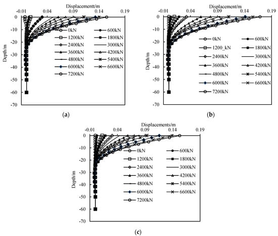
Figure 8.
The horizontal displacement along with depth under different horizontal loads: (a) H = 0.1 MN, (b) H = 0.3 MN, and (c) H = 0.5 MN.
It can be observed that, under a constant horizontal load, increasing the vertical pressure significantly increases the pile’s horizontal displacement above the inflection point. This is because the vertical pressure, no longer acting purely as an axial force, can be considered as an eccentric load to some extent. Consequently, a higher vertical pressure results in a larger bending moment in the pile, leading to larger horizontal deformation.
Comparing the results in Figure 8, it is evident that increasing the horizontal load has little effect on the pile head’s horizontal displacement for the same vertical pressure. The inflection points are not obvious in the figures, and they occur at approximately the same depth (around −25 m). Displacements below the inflection points are also relatively small. This suggests that the vertical bearing characteristics of the pile are not significantly affected by horizontal loads, possibly due to the small values in horizontal loads across the levels analyzed.
Therefore, judging from the above results, the presence of horizontal force decreases the vertical compressive bearing capacity of the pile foundation, but the effect is limited, to within 20% of the total value. Under a constant horizontal load, increasing the vertical pressure results in increased deformation of the pile above the inflection point.
3.3. The Impact of Existing Horizontal Forces on Uplift Bearing Capacity
Figure 9a shows the vertical displacement at the pile head at different uplift force with fixed horizontal loads. It is evident that the existence of a fixed horizontal load at the pile head has a negative effect on the uplift bearing capacity of the pile. The curve of vertical displacement along with depth for a fixed horizontal load of 5 MN reflects the lowest uplift bearing capacity, while the curve for 1 MN corresponds to the highest uplift bearing capacity, although the difference is not significant. This indicates that, compared to compressive bearing capacity, horizontal loads have a limited impact on the pile’s uplift bearing capacity.
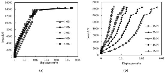
Figure 9.
The (a) uplift load–vertical displacement and (b) uplift load–horizontal displacement curves of a pile at mudline at different lateral loads.
Figure 9b illustrates that as the uplift force increases, the horizontal displacement of the pile also increases, with the rate of increase becoming more pronounced in the later stages of uplift force application. For a given uplift force, a higher applied horizontal load results in a greater rate of increase in horizontal displacement with increasing uplift force. In summary, while the presence of horizontal loads does negatively affect the pile’s uplift bearing capacity, the extent of this impact is relatively small compared to its effect on compressive bearing capacity. Additionally, an increase in uplift force results in a greater horizontal displacement at the pile head under a fixed horizontal load.
Thus, in this section, it can be seen that the presence of horizontal load reduces the tensile horizontal bearing capacity of the pile foundation, but the influence is limited; the reduction effect is within 10%. On the other hand, an increase in uplift force results in a significant decrease in the horizontal bearing capacity of the pile.
3.4. The Bearing Capacity Envelope of the Pile
To further reveal the impact of existing loads at the pile head on the pile’s bearing characteristics, the limit bearing capacity envelopes under the V–H (vertical–horizontal) loading conditions for the foundation are plotted based on the above calculation results. Firstly, a normalization method is used to reflect the dimensionless bearing capacity envelope of the pile foundation. According to the recommended method of dimensionless normalization of loads and displacements, under complex loading conditions, where H represents the horizontal load at the pile head, V represents the vertical load, u represents the horizontal displacement, and w represents the vertical displacement, the dimensionless forms of the loads and displacements are given in Table 4.

Table 4.
Dimensionless normalization of loads and displacements.
In this paper, Vult and Hult are both based on field test data from Pan [] and are 10,400 kN and 1000 kN, respectively. The failure envelope is drawn using the method proposed by Yun et al. []. The obtained pile bearing capacity envelope is shown in Figure 10. According to the bearing capacity envelope formula proposed by Liu et al. [], the expression for the bearing capacity envelope is given by:
where the value of p ranges from 0.12 to 0.2 [].
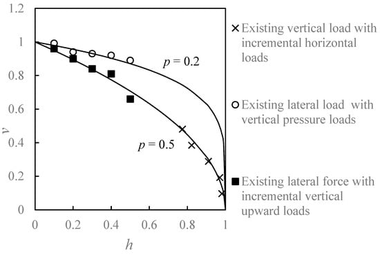
Figure 10.
Bearing capacity envelopes of piles under V–H loads.
From Figure 10, the abscissa represents the normalized horizontal ultimate bearing capacity of a pile (H/Hult), and the ordinate represents the normalized vertical ultimate bearing capacity of a pile (V/Vult). The results of the ultimate vertical compressed bearing capacity under an existing vertical load fit well with the curve described by Equation (1) at p = 0.2, while the ultimate lateral compressed bearing capacity under an existing lateral load and the ultimate uplift bearing capacity under an existing lateral load matched well with the curve when p = 0.5. This means that loading strategy has a significant influence on a pile’s bearing capacity envelope. For a flexible pile with a diameter of 2.8 m under combined loads, the failure envelope can be described by Equation (1) with p = 0.2 to 0.5. This is larger than the results from Liu et al. [] (p = 0.12 to 0.2). The main reason is that the former is a typical flexible pipe pile, while the foundation described by Liu et al. [] is a semi-rigid or rigid bucket foundation.
4. Conclusions
In this paper, numerical simulation was used to investigate the effects of vertical load on horizontal bearing capacity, as well as the effects of horizontal load on the compressive and tensile bearing capacities of a typical, long, flexible pile foundation with a diameter of 2.8 m. The research explored various combinations of horizontal and vertical loading patterns. The novelty of this investigation is to reveal the nonlinear interactions between vertical and horizontal loads and to propose comprehensive bearing capacity envelopes for such pile types. The conclusions are as follows:
- (1)
- Slightly increasing the vertical pressure within 10% of the ultimate vertical bearing capacity can improve the horizontal bearing capacity of the pile foundation, while this effect works the opposite way if the vertical pressure is larger than 10% of the value.
- (2)
- Horizontal force has a negative effect on the vertical compressive bearing capacity of the pile foundation, but the effect is within 20% of the ultimate value. The negative effect mainly appeared above the first inflection point of the pile.
- (3)
- The presence of horizontal thrust causes a limited reduction in the vertical tensile bearing capacity of the pile foundation, which is within 10% of the ultimate value.
- (4)
- An envelope curve and fitting formula for the foundation bearing capacity under combined V–H action were derived, with the exponent p varying from 0.2 to 0.5.
This study provides a convenient method for predicting the bearing characteristics of large-diameter flexible piles under complex loads. However, for an offshore structure, cyclic loads such as wind, waves, and current are important. The current research fails to consider the bearing capacity of large-diameter flexible piles under cyclic loading. Consequently, one possible future research direction is to select a novel soil constitutive model to simulate long-term cyclic loading effects on this kind of foundation.
Author Contributions
Methodology, X.Y. and W.G.; software, X.Y. and Q.Y.; validation, X.Y., W.G. and Q.Y.; writing—original draft preparation, X.Y.; writing—review and editing, X.Y.; supervision, Q.Y.; project administration, W.G.; funding acquisition, W.G. All authors have read and agreed to the published version of the manuscript.
Funding
This work was supported by the National Natural Science Foundation of China (No. 52378328, 52208333, 52178317) and Research Fund for Advanced Ocean Institute of Southeast University (Key Program KP202404; Major Program GP202403). The authors are grateful for their support.
Data Availability Statement
Data available on request due to privacy. The original contributions presented in the study are included in the article, further inquiries can be directed to the corresponding author/s.
Conflicts of Interest
The authors declare no conflict of interest.
References
- Qin, W.; Cai, S.; Dai, G.; Wang, D.; Chang, K. Soil Resistance during Driving of Offshore Large-Diameter Open-Ended Thin-Wall Pipe Piles Driven into Clay by Impact Hammers. Comput. Geotech. 2023, 153, 105085. [Google Scholar] [CrossRef]
- Li, X.; Dai, G.; Zhang, F.; Gong, W. Energy-based analysis of laterally loaded caissons with large diameters under small-strain conditions. Int. J. Geomech. 2022, 22, 05022005. [Google Scholar] [CrossRef]
- Li, X.; Dai, G. Closure to ‘Energy-Based Analysis of Laterally Loaded Caissons with Large Diameters under Small-Strain Conditions’. Int. J. Geomech. 2023, 23, 07023008. [Google Scholar] [CrossRef]
- JTG D63-2007; Code for Design of Ground Base and Foundation of Highway Bridges and Culverts. China Communications Press: Beijing, China, 2007.
- JTS 147-1-2010; Code for Soil Foundations of Port Engineering. China Communications Press: Beijing, China, 2010.
- Jiang, J.; Cai, S. Comparison of the bearing characteristics of tip resistance and shaft resistance for large diameter and super-long pile. Ind. Constr. 2017, 47, 95–101. [Google Scholar]
- Gu, G.; Zhao, C.; Li, S.; Zhao, C.; Xu, J. Laboratory model tests on bearing character of single pile under combined load in sand. Chin. J. Geotech. Eng. 2011, 33 (Suppl. 2), 379–383. [Google Scholar]
- Liu, J. Analysis of m Method for Pile Foundation Based on Horizontal Load and Inclined Load; Tianjin University: Tianjin, China, 2009. [Google Scholar]
- Li, S.F.; Zhao, C.F.; Xian, F.R.; Xie, X.L. Bearing mechanism of single pile under combined loads. J. Guangxi Univ. Nat Sci Ed. 2013, 38, 969–974. [Google Scholar]
- He, L.; Chen, X.; Wang, Z.; Han, Y.; Su, T.; Dai, G.; Zhang, E.; Long, Z. A case study on the bearing characteristics of a bottom uplift pile in a layered foundation. Sci. Rep. 2022, 12, 22457. [Google Scholar] [CrossRef]
- Chen, W.; Sarir, P.; Bui, X.-N.; Nguyen, H.; Tahir, M.M.; Armaghani, D.J. Neuro-genetic, neuro-imperialism and genetic programing models in predicting ultimate bearing capacity of pile. Eng. Comput. 2020, 36, 1101–1115. [Google Scholar] [CrossRef]
- Chen, R.; Zhen, Z.; Kong, L.; Lin, D. Analysis method for pile groups subjected to lateral and torsional loads. Chin. J. Geotech. Eng. 2013, 35, 1463–1469. [Google Scholar]
- Zhuang, P.; Qi, L.; Zhou, Z. Analysis of the influence factors of the bearing capacity of single pile under lateral load. Highway 2013, 12–19. [Google Scholar] [CrossRef]
- Haiderali, A.; Nakashima, M.; Madabhushi, S. Cyclic lateral loading of monopiles for offshore wind turbines. In Proceedings of the 3rd International Symposium on Frontiers in Offshore Geotechnics, ISFOG 2015, Oslo, Norway, 10–12 June 2015. [Google Scholar]
- Pan, D.; Lucarelli, A.; Cheng, Z. Field Test and Numerical Analysis of Monopiles for Offshore Wind Turbine Foundations. Geotech. Struct. Eng. Congr. 2016, 2016, 1138–1152. [Google Scholar]
- Mu, L.; Kang, X.; Li, W. Analytical method for single pile under V-H-M combined loads in sand. Chin. J. Geotech. Eng. 2017, 39, 153–156. [Google Scholar]
- Liang, F.; Zhang, H.; Chen, S. Effect of vertical load on the lateral response of offshore piles considering scour-hole geometry and stress history in marine clay. Ocean Eng. 2018, 158, 64–77. [Google Scholar] [CrossRef]
- Jiang, J.; Yu, Y.; Gong, J.; Fu, C. Analytical method for lateral capacity of pile foundations under vertical loads considering asymmetric scour hole in sand. Ocean Eng. 2024, 293, 116654. [Google Scholar] [CrossRef]
- Qin, W.; Cai, S.; Dai, G.; Wei, H. Analytical solutions of soil plug behaviors in open-ended pile driven by impact load. Acta Geotech. 2023, 18, 4183–4194. [Google Scholar] [CrossRef]
- Li, X.; Dai, G.; Zhu, M.; Zhu, W.; Zhang, F. Investigation of the soil deformation around laterally loaded deep foundations with large diameters. Acta Geotech. 2024, 19, 2293–2314. [Google Scholar] [CrossRef]
- Liu, H.; Zhu, M.; Li, X.; Dai, G.; Yin, Q.; Liu, J.; Ling, C. Experimental study on shear behavior of interface between different soil materials and concrete under variable normal stress. Appl. Sci. 2022, 12, 11213. [Google Scholar] [CrossRef]
- Li, X.-J.; Zhu, M.-X.; Dai, G.-L.; Wang, L.-Y.; Liu, J. Interface Mechanical Behavior of Flexible Piles Under Lateral Loads in OWT Systems. China Ocean Eng. 2023, 37, 484–494. [Google Scholar] [CrossRef]
- Li, W.; Li, X.; Wang, T.; Yin, Q.; Zhu, M. The Simplified Method of Head Stiffness Considering Semi-Rigid Behaviors of Deep Foundations in OWT Systems. Buildings 2024, 14, 1803. [Google Scholar] [CrossRef]
- Li, X.; Dai, G.; Gong, W.; Zhao, X. A numerical study into the impact of soil coring on lateral capacity of piles with large diameter. In Proceedings of the 27th International Ocean and Polar Engineering Conference, San Francisco, CA, USA, 25–30 June 2017. ISOPE-I-17-211. [Google Scholar]
- Yun, G.; Bransby, M. The horizontal-moment capacity of embedded foundations in undrained soil. Can. Geotech. J. 2007, 44, 409–424. [Google Scholar] [CrossRef]
- Liu, R.; Lei, W.; Ding, H. Failure envelopes of large-diameter shallow buried bucket foundation in undrained saturated soft clay under combined loading conditions. Chin. J. Geotech. Eng. 2014, 36, 146–154. [Google Scholar]
Disclaimer/Publisher’s Note: The statements, opinions and data contained in all publications are solely those of the individual author(s) and contributor(s) and not of MDPI and/or the editor(s). MDPI and/or the editor(s) disclaim responsibility for any injury to people or property resulting from any ideas, methods, instructions or products referred to in the content. |
© 2024 by the authors. Licensee MDPI, Basel, Switzerland. This article is an open access article distributed under the terms and conditions of the Creative Commons Attribution (CC BY) license (https://creativecommons.org/licenses/by/4.0/).