Abstract
A swimming pool in Corrales de Buelna (Cantabria) was demolished in March 2017 due to the loss of mechanical performance of the laminated timber structure. The relevant deterioration was caused by rotting of the wood and corrosion of the metal connecting elements. The structure featured a barrel vault with five large tri-articulated arches enclosed on the sides by inclined facades formed by toral rafters and purlins. The corresponding diagnostic process involved data collection and structural assessments to verify the structure’s bearing capacity and serviceability. Data collection was carried out in December 2015 and consisted of a thermal camera inspection to determine the points of moisture accumulation and sampling openings, conduct environmental and wood hygrothermal measurements, and measure cross-sectional losses and deformations of the structural elements. Verification of the load-bearing capacity was carried out using matrix calculation structure software for both the original and deteriorated structure. The diagnosis indicated that the damage was caused by leaks in the joints of the aluminum composite roof panels and by the insufficient load-bearing capacity of the structure. The severity of the damage compromised the mechanical strength and stability of the building, leading to a recommendation that the use of the facilities be immediately discontinued. The degree of deterioration left the structure unrecoverable, making it very difficult to apply reinforcement measures. These factors led to the structure’s demolition to prevent its collapse.
1. Introduction
1.1. Construction Type of the Indoor Swimming Pool
Indoor swimming pools are a type of construction characterized by a large space in which the pools are housed. Attached to this area are a block of server spaces in which access zones, changing rooms, toilets, and installation rooms are distributed. The swimming pool space has a roof with a large span and height, while the server space block usually features flat slab structures with reduced heights. For municipal swimming pools, a gymnasium space is usually included to provide comprehensive sports facilities for the municipality.
The pool space is also heated to allow its use in winter. The large mass of water in evaporates over time, which raises the relative humidity of the environment. This humidity must be controlled with ventilation, usually mechanically.
Glulam is one of the most effective and efficient materials for these long-span roofs, leading to its widespread use. This material’s high bending strength allows it to withstand the stresses that occur in this type of structure, while its low density reduces the weight of the structure.
1.2. The Swimming Pool of Corrales de Buelna
The Corrales de Buelna Indoor Swimming Pool was an isolated building with a rectangular ground plan measuring 38 × 30 m in an east–west direction, with a cylindrical vault starting from the ground. The east and west gable walls were flat and sloping (Figure 1). A two-story building was attached to the north side. This building housed the entrance and changing rooms on the ground floor and the gymnasium on the upper floor. There was also a basement that housed the swimming pool facilities.
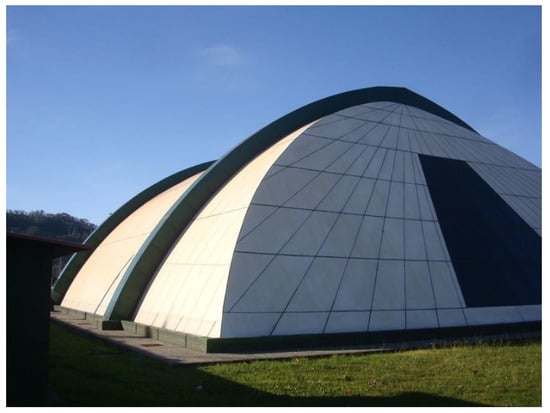
Figure 1.
Exterior of the indoor swimming pool.
The foundations were composed of insulated reinforced concrete footings. The roof structure consisted of arches and beams of glued laminated timber with a strength class of GL24h. The beams were closed with wooden sandwich panels consisting of wooden waterproof boards on the external face, an extruded polystyrene core (XPS), and spruce tongue-and-groove boards on the internal face. The structure of the semi-detached building consisted of reinforced concrete columns and slabs.
The envelope consisted of aluminum composite panels anchored to the wooden sandwich panels via aluminum omega profiles and sealed with silicone. The sloping gables featured an aluminum and glass curtain wall.
The pool was opened to the public on 20 July 2003, and in the first years of operation, the first signs of humidity appeared on the roof. Initially, the humidity was identified as condensation or a product of the building work, which led to the use of polyurethane on the inside face of the wooden sandwich panel (on the cylindrical roof) together with the installation of a false ceiling composed of removable aluminum slats on the entire roof.
In the following years, the wooden structure began to deteriorate, and in 2016, an investigation began to investigate the causes and origin of this damage. The study concluded that the structure in its deteriorated state was not safe, which led to the subsequent closure of the facility to the public. The wooden structure’s state of deterioration indicated that the structure was unrecoverable, with a recommendation to demolish it. This demolition was carried out in 2017, fourteen years after the pool’s inauguration (Figure 2).
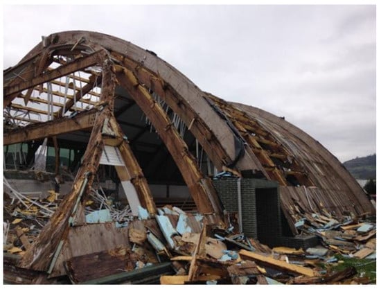
Figure 2.
Building demolition.
1.3. Pathology of a Timber Structure
Generally, damage to a timber structure is caused by design defects, construction defects, maintenance defects, or extraordinary loads (not foreseen in the design). A study of 127 timber structure failures in Sweden concluded that 53% of the damage was caused by design defects, 27% by construction defects, 11% by material defects due to lack of maintenance, 4% by extraordinary loads, and the remaining 5% by unknown causes []. Therefore, a large portion of the damage is due to errors that could be avoided by improving the management of construction processes and control in the design phase.
Collapses due to design or execution failures occur in the first few years after building a structure. For example, the collapse of the Siemens Arena structure in Ballerup, Denmark in 2003 [] occurred one year after its opening and was caused by a defect in the design of the roof truss nodes. The collapse of the Exhibition Hall in Jyväskylä, Finland, in 2003 also occurred due to a defect in the construction of the truss nodes [].
In other cases, collapse occurs due to degradation of the wood caused by humidity. In some cases, degradation is a long-term process. For example, the Bad Reichenhall Sports Hall in Germany collapsed in 2006 due to degradation of adhesives in the laminated timber under high humidity, 34 years after the structure’s inauguration []. In this case, the origin of the collapse was a defect in the roof maintenance.
Wood degradation usually occurs due to attacks by xylophagous fungi and insects. The advantage of this type of attack is that degradation is relatively slow and can be detected at an early stage with proper maintenance. Therefore, in many cases, it is possible to take measures to prevent the attack from progressing before the collapse of the structure becomes irreversible. The preservation of wood is linked to its moisture content, which is the main factor responsible for the appearance and proliferation of xylophagous fungi and insects []. Xylophagous fungi require moisture contents above 17% [], with optimal values between 25 and 55% []. On the other hand, the most common xylophagous insects with a larval cycle can attack wood with moisture contents between 10% and 60%, although their optimal value is around 30% []. Therefore, to reduce the probability of an attack, the moisture content of the wood is generally recommended to remain below 20%; this value should only be exceeded for very temporary and short-term periods. For indoor swimming pools, the management of the building requires controlling the relative humidity levels of the environment so that the moisture content of the wood does not exceed the values enabling the growth of xylophages. Structural timber placed inside an indoor swimming pool is considered class 2 because it is located under cover and not exposed to the weather but remains subjected to occasional, non-persistent wetting [].
Generally, glued-laminated timber structures offer strong seismic performance due to their low stiffness and high elastic deformation capacity. However, damage from earthquakes can be reinforced using self-tapping screws and Carbon-Fiber-Reinforced Polymer (CFRP) []. The use of both self-tapping screws and CFRP fabric reinforcements reduces the initiation and progression of cracks in the connections. In addition, this method provides greater ductility at the connections, enabling greater dissipation of seismic energy.
1.4. Damage Detection
In recent years, new techniques have been implemented for detecting damage to timber structures based on 3D point cloud [] and studying acceleration vibration signals. These data can be analyzed using methods based on neural models and Bidirectional Gated Recurrent Units in parallel [] or conditional diffusion models with data fusion [].
The use of non-destructive acoustic techniques to inspect existing timber structures has been well researched in recent years [,,,,]. However, these investigations have generally focused on sawn timber, which is the variety found in ancient buildings. More modern wood products, such as glued laminated timber (glulam) or cross-laminated timber (CLT), have not yet been studied in depth using these types of non-destructive techniques. Therefore, there are currently no analytical equations that have been sufficiently verified experimentally relating the dynamic modulus of elasticity, obtained using acoustic methods, to the strength and stiffness of these elements.
Glued laminated timber is a product that was developed at the beginning of the 20th century. There are now numerous examples of lesions and deterioration of this material that need to be studied. Against this background, some research has sought to characterize glulam pieces by means of non-destructive techniques [,,].
2. Methodology
2.1. Designation of Structural Elements
To identify structural elements (Estructuras de Madera Laminada Yofra, S.A., Cantabria, Spain), the arches are named Axx, the beams of the west sloping façade are named Bxx, and those of the east façade are named Cxx, where xx is the numbering within the type. Figure 3 shows the plan of all structural elements with their numbering categories.
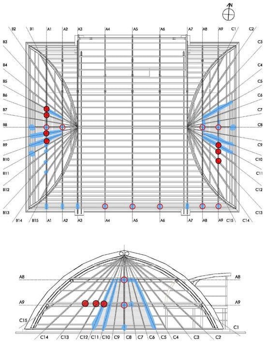
Figure 3.
Plan and section with the location of damage (blue—soft rot fungi; red—breakage of connections).
2.2. Inspection
To assess the different constructive elements of the building, a visual inspection was carried out in several parts of the pool. Lower areas of the structure were inspected by demolishing the brick coverings of the supports of the structural elements. Elevated areas of the structure were inspected using a lifting basket. The interior of the timber was inspected by drilling holes with a 10 mm diameter drill bit and extracting timber cores with a 25 mm diameter hollow drill bit. Finally, the roof was inspected. For this process, the false ceiling was dismantled, holes were opened in the wooden sandwich panel, and some panels of the exterior roof were lifted.
Measurements were taken in the environment using an Extech MO295 thermo-hygrometer (Extech Instruments, Hudson, NH, USA). Specifically, the relative humidity, dry bulb temperature, dew point, and surface temperature of the interior walls were recorded using infrared.
Measurements were also carried out on the glulam structure using the following devices:
- An Extech MO295 xylohygrometer (Extech Instruments, Hudson, NH, USA) for measuring the moisture content with needles (Figure 4);
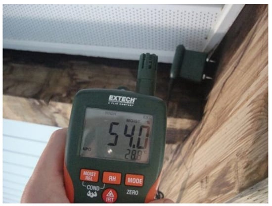 Figure 4. Measurement of wood temperature and moisture content with a needle thermohygrometer.
 - An infrared thermal camera model ‘i7′ from FLIR for recording the surface temperature;
- A PCE-VE 310 video endoscope for inspecting the condition of the wood inside;
- A portable digital microscope model ‘UM039′ from Mustech Electronics Co. for inspecting the detritus of xylophagous organisms;
- A digital caliper for measuring wood section losses.
Finally, the strength of the entire structure was checked using Cype3D 2015 matrix calculation software.
2.3. Structural Analysis
Initially, the analysis was carried out on the original structure, i.e., with the cross-sections of the arches prescribed in the project. Subsequently, a new analysis was carried out considering the residual resistant section that remained after being attacked by xylophagous fungi.
2.3.1. Software
The structure’s compliance with limit states was verified using three-dimensional structural analysis software (Cype 3D 2015). This software uses the matrix calculation method for members and nodes and represents an application of the finite element method to one-dimensional member-type elements.
2.3.2. Mechanical Loads
Loads were estimated according to the CTE DB SE-AE standard [], considering the roof’s cylindrical shape and the location (Cantabria is located at an altitude of less than 2000 m). Based on the originating causes, loads were classified into dead loads (self-weight), live loads (maintenance), environmental loads (wind and snow), and accidental loads (fire).
Dead loads were estimated based on the self-weights of the structural and roof elements, as follows:
- Density of wood: 3.80 kN/m3;
- Wood sandwich panel: 0.22 kN/m2;
- Aluminum composite panel: 0.10 kN/m2.
A maintenance live load of 0.4 kN/m2 was applied in the accessible and upper areas of the roof with slopes of less than 40°.
Dynamic effects caused by wind were not considered due to the building’s slenderness (height/width less than 6). The static wind pressure was obtained using Formula (1):
where qb represents dynamic wind pressure (Spain, 0.5 kN/m2), ce is the exposure coefficient according to the roughness of the surroundings (flat rural land without significant obstacles or trees, with a height of 12 m, 2.8), and cp is the pressure or suction wind coefficient according to the shape and orientation of the building. The values of cp were obtained from the graph in Figure 5, with a pressure wind coefficient of 0.8 in zone A and suction coefficients of −1.2 in zone B and −0.4 in zone C.
qe = qb × ce × cp,
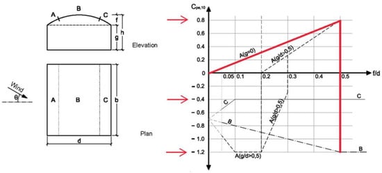
Figure 5.
Pressure or suction wind coefficients on a cylindrical roof (CTE DB SE AE) [].
A snow load of 0.3 kN/m2 was applied only to the upper part in roof areas with a slope less than 30°.
Accidental loads were accounted for by removing the sections burnt by fire during the 30 min evacuation.
Load factors to assess strength and stability followed the CTE DB SE standard [] (Table 1).

Table 1.
Load Factors.
2.3.3. Mechanical Properties of Timber
The structure was built with Glued Laminated Timber, GL24h, and its mechanical properties were obtained from the CTE DB SE-M standard [] (Table 2).
Table 2.
Mechanical properties of Glued Laminated Timber.
2.3.4. Structure Modelling
The three-hinged arches were modelled as a ten-sided polygon. The arches were hinged at the supports and the keystone. The remaining elements were simple beams or columns on two pinned supports.
According to project data, the cross-sections of all elements were constant.
A stability analysis was also applied according to the equivalent member method. The buckling lengths of the elements were defined as the lengths between bracing points.
2.3.5. Ultimate Limit States (Strength)
The Ultimate Limit State of the timber was verified by determining the ratio of stress to the ultimate limit values according to the mechanical properties of the laminated timber (GL24h), as indicated in Section 2.3.3.
The moisture content of the wood and the duration of loading were determined using the kmod coefficient defined in the CTE DB SE-M standard []. This coefficient reduces the characteristic strength of the material as a function of these two parameters. In terms of moisture content, the wood inside the heated swimming pool corresponds to Service Class 2 (wood moisture content corresponding to a temperature of 20 ± 2 °C and a relative air humidity exceeding 85% only a few weeks of the year). The dead load (self-weight) has a permanent loading duration corresponding to a kmod of 0.6. However, the live load (maintenance) and environmental load (wind and snow) have a short duration corresponding to a kmod of 0.9. Finally, the accidental load (fire) has an instantaneous duration corresponding to a kmod of 1.1.
2.3.6. Serviceability Limit States (Deformation)
The Serviceability Limit State was verified by determining the ratio of strain to the limits established in the CTE DB SE standard [], as follows:
- Deflections: Instantaneous deformations in beams, s/300 (where s is the span of the beam);
- Horizontal displacements: Total deflection, h/500 (where h is the total height of the building).
3. Results
3.1. Hygrothermal Conditions
The environmental conditions outside the pool were as follows:
- Ambient temperature: 13.2 °C;
- Relative humidity: 57%.
During the visit, the air-conditioning system was operating normally, and the ambient conditions inside the pool were as follows:
- Ambient temperature: 29.7 °C;
- Relative humidity: 62%;
- Dew point: 20.7 °C.
Under these conditions of humidity and ambient temperature, using an abacus with wood hygroscopic equilibrium curves [] provided an equilibrium moisture content of around 11% for the wood. This moisture content value indicates that the air-conditioning conditions of the pool were adequate, as the probability of the wood being attacked by a xylophagous agent was very low.
The surface temperature of the materials inside the envelope was also measured, and the following average values were obtained:
- Wood: 28.8 °C;
- False ceiling: 27 °C;
- Aluminum profiles: 27 °C.
3.2. Damage and Injuries
Structural elements made of glulam that were visible or uncovered via sampling openings were inspected. It was not possible to inspect the purlins and the upper parts of the arches and beams, which were hidden behind the polyurethane foam and the false ceiling installed in 2006.
The following damage to the glulam structure was observed (illustrated in Figure 3):
- Soft rot fungi. In the optical microscope images taken, it was possible to observe disintegration of the wood alongside a spongy residue with a fibrous appearance, typical of soft rot fungi that attack the cellulose and hemicellulose of the wood leaving remains of lignin under conditions of very high moisture content (Figure 6). This attack gives the wood a soft consistency. Black spots were also observed in the areas with rot. This damage was located in numerous elements, as follows: in the south foundation supports of all the arches where the sections lost due to rotting were 4.3 cm or smaller in size (Figure 7) (in the residual section, the depth of attack was estimated by observing the color and consistency of sawdust coming out of the drill hole, establishing a depth of 2 cm (Figure 8)); in all the foundation supports of uncovered façade pairs; in the upper faces of pairs B5, B9, B10, C5, C10, and C11; in the supports for the horizontal beams of arches A1 and A2; in toral rafter B8; in the horizontal beams of arches C5, C10, and C11; in toral rafter C8; in the supports of pairs B11, B12, B13, and B14 in the horizontal beam of arch A1; in the lower area of the sandwich panel between arches A06 and A07; and in the area behind the false ceiling between arches A08 and A09.
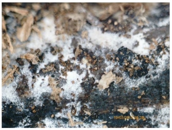 Figure 6. Microscopy of soft rot fungi.
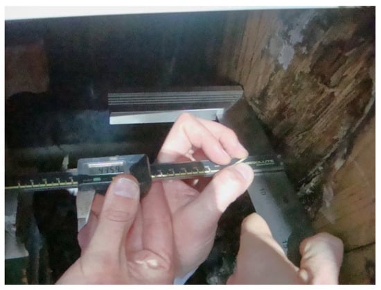 Figure 7. Measurement of sectional loss due to wood rot using a digital caliper.
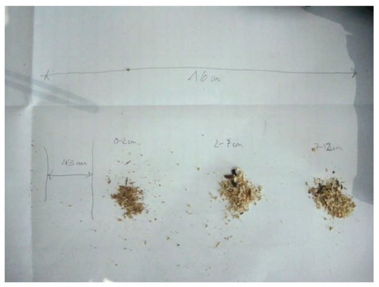 Figure 8. Sawdust extracted from a 16 cm hole drilled at the base of the arch. The depth of each extraction from the 4.3 cm sectional loss is indicated.
- Breakage of connections. The second-order elements of the structure were joined to the first-order elements via structural screws for wood (Figure 9). The screws were broken in the inclined facades—specifically at the connections of pairs B5, B6, B9, and B10 in the horizontal beam of arch A1 and at the connections of pairs C10, C11, and C12 in the horizontal beam of arch A9. It was observed that reinforcement fittings were placed in the previously broken connections of pairs B2, B3, B4, B5, and B6 on the horizontal beam of arch A1.
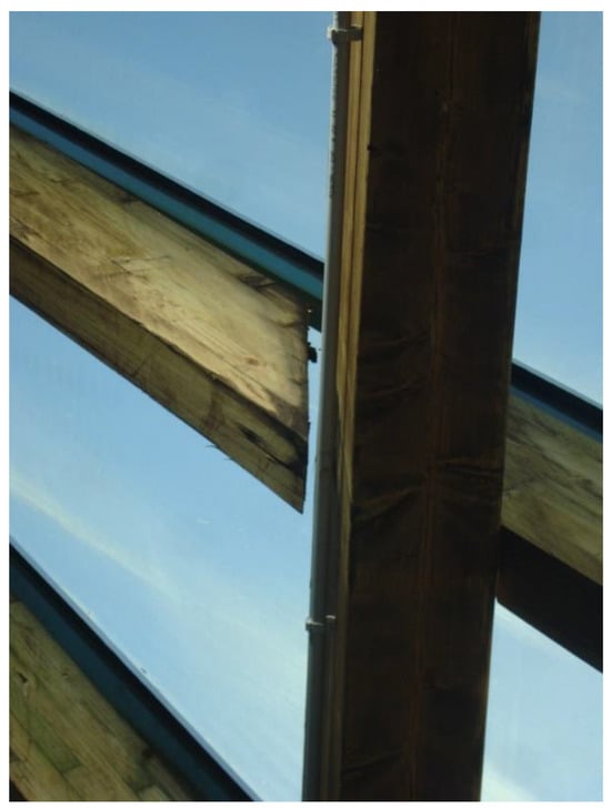 Figure 9. Breakage of fixings between the pair and beam.
- Corrosion of metal connections. Corrosion was observed in the metal elements used in the supports of the toral rafter, specifically in the connections of the horizontal beams of arches A1 and A2, in toral rafter B8, and in the connections of the horizontal beams of arches A8 and A9 in toral rafter C8 (Figure 10). Corrosion was also found in the supports of all the arches. To prevent this type of corrosion, it is recommended to employ screws and washers made from the same metal, use stainless-steel fasteners, or apply a waterproof plastic film coating such as epoxy resin [].
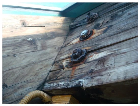 Figure 10. Corrosion of nuts, washers, and threaded rods in beam connections.
- Excessive deformations. On the day of the visit, the weather conditions were ideal, with no wind or snow, which could have led to extreme serviceability of the structure. Very high deflection was observed in the horizontal beams of the gables in arches A1 and A9. The deflection at the mid-point was 10 cm for an 11 m span element, corresponding to a span/110 deflection (Figure 11).
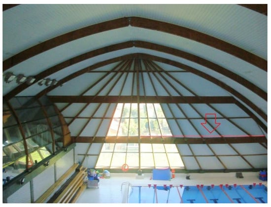 Figure 11. Deflection of a horizontal beam in the inclined façade.
3.3. Moisture Content of Timber
It was also found that the moisture content of rotten areas on the supports of arches ranged from 23.7% to 68%, with lower sections being the wettest. In the upper areas of arches featuring no rotting, the moisture content was 15%. In the remaining areas without detectable rot, the moisture content ranged from 54% to 87.6%.
There is a relationship between temperature and moisture content in hygroscopic materials such as stone, ceramics, and wood, enabling one to estimate the moisture content of wood with a thermographic camera [,] (Figure 12).
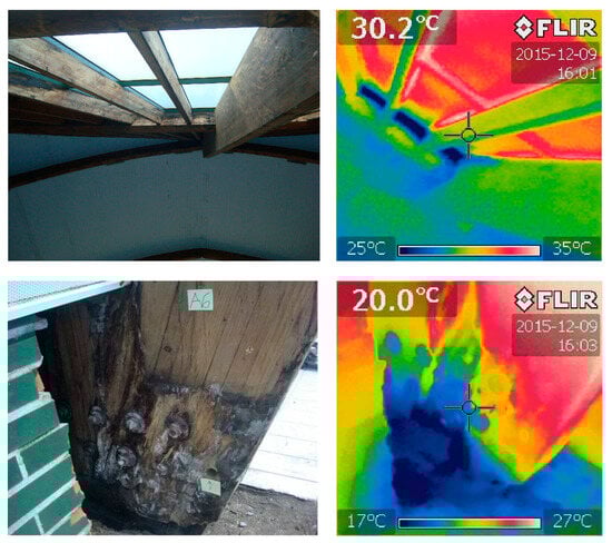
Figure 12.
Thermal camera images of the toral rafter’s foundation and A6 arch support. An RGB image is presented on the right.
3.4. Structural Assessment
The following loading assumptions were made for the structure in the original and damaged state using the current standards [,,] (Figure 13). The complete structure was entered into the structural analysis software to verify the strength, deformation, and stability of the elements considering the original undamaged structure and the damaged structure. Table 3 shows the mechanical capacity at which the arches (the main element of the structure) are working.
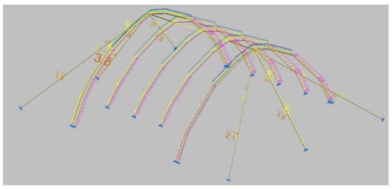
Figure 13.
Loads (yellow: permanent; magenta: longitudinal wind; orange: transversal wind; green: maintenance; blue: snow).
Table 3.
Ultimate Limit State (ULS) and Serviceability Limit State (SLS) of arches.
It can be seen that the arches were already slightly undersized in the original structure, as they were stressed to more than 100% of their mechanical capacity, both in normal and fire situations (considering 60 min of fire duration). In addition, the arch keystone drop was 157 mm, which is more than allowed by the standard, of 97 mm (arch span/300). Finally, the arches of the damaged structure still did not meet the strength requirements. Therefore, the results revealed non-compliance with current regulations, requiring more overall strength and stiffness in the structure.
3.5. Roof Construction System
The roof was constructed using aluminum composite panels with a polyethylene core. A substructure of vertically fixed extruded aluminum omega profiles was placed on top of the wooden sandwich panel board, which was then fastened with screws to the wooden board (Figure 14). The aluminum composite panels were glued to this substructure with a polyurethane adhesive.
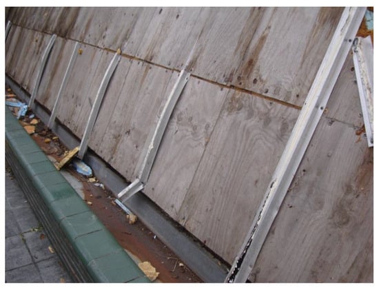
Figure 14.
Aluminum omega profiles screwed to the wooden sandwich panel. Image taken during the demolition process.
Vertical joints between panels had different omega joint profiles but with the wings facing upwards. The omega profile was filled with foamed polypropylene and sealed with silicone (Figure 15). The seals showed damage and vegetation growth.
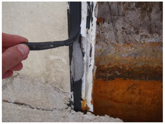
Figure 15.
Aluminum omega profiles placed in the vertical joint between the composite panels. The section is filled with a foamed polypropylene as the bottom of the joint and sealed with silicone.
4. Discussion
4.1. Damage
The wood was attacked by xylophagous rot fungi due to the presence of a high moisture content. In situ measurements showed that areas with the presence of fungi had wood moisture contents higher than 20% (much higher than the recommended limit of 17%). If the moisture content had been lower, the wood would not have been exposed to an attack.
Soft rot was generated due to the high ambient humidity, which increased the wood’s moisture content. This type of fungus develops inside the wood cell wall and mainly attacks the cellulose of the secondary wall, leaving the wood with a soft and spongy appearance, alongside a corresponding loss of strength.
In softwoods such as those in this structure, black stains may appear due to the constant cyclical changes in moisture content. Woods have free acids that are exuded during drying. Thus, when the wood is subjected to continuous wetting and drying cycles, there acid is constantly produced through a process of hydrolysis, which generates dark-colored iron compounds on the wood surface.
Corrosion of the steel connecting elements in wood is caused by high ambient humidity. The corrosion of steel requires water to act as an electrolyte, so humid environments make it possible for corrosion to occur. The corrosion process of steel is also aggravated by wood moisture content since it accelerates in acidic environments. Spruce wood has a pH of 5 [] due to the presence of free acids. Acetic acid is exuded during wood drying processes. Under normal conditions, wood is placed dry, so the acetic acid never comes in contact with steel bolts and plates. In this case, however, the wood was continuously wetted and dried. Consequently, acetic acid was continuously produced and came into contact with the steel, lowering its pH and accelerating the corrosion process. This factor explains the high degree of deterioration on the steel connecting elements of the timber structure.
Seepage occurred through the screws fixing the aluminum profiles to the wooden sandwich panel (Figure 16). The water first penetrated through the silicone seals between the aluminum composite panels and then ran along the omega profiles acting as a channel, eventually seeping to lower layers through the screws fixing the profile to the wood sandwich panel (Figure 17 and Figure 18).
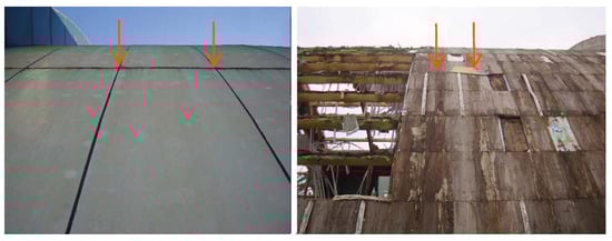
Figure 16.
Left of the image: composite roof panels before demolition. Right of the image: the wooden sandwich panel during the demolition process. Red arrows indicate areas of water seepage through the composite roof panels.
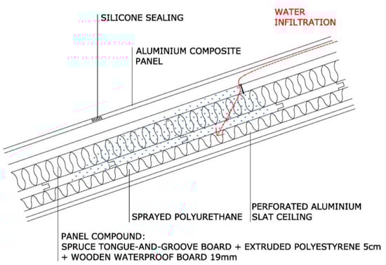
Figure 17.
Construction cross-section of the roof indicating its construction elements and water seepage points.
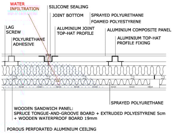
Figure 18.
Longitudinal constructive section of the roof with indications indicating its constructive elements and water seepage points.
The deterioration process of the seals was accelerated by the excessive movements to which they were subjected due to the high deformability of the structure. These movements occurred in situations of wind and rain due to excessive horizontal deformation of the structure, which was not braced on the plane of arch.
One of the most severely damaged areas was located in the timber structure under the aluminum curtain wall. The leaks in this area occurred at the junction between the aluminum composite panels and the curtain wall, as the watertightness relied on a silicone seal, without any type of waterproofing reinforcement.
4.2. Recommendations
Once the structure’s advanced state of deterioration had been analyzed, immediate closure of the facilities was recommended to avoid the risk of accidents caused by structural collapse. While the pool was closed, one of the vertical pairs on the east sloping façade became detached (the one numbered C6). It was finally concluded that the best option was to demolish the pool and rebuild it.
5. Conclusions
The case of the Corrales de Buelna swimming pool offers a good example of the need to diagnose the causes and origins of structural damage. The incorrect initial diagnosis, which attributed the signs of humidity to condensation, led to interior thermal insulation that only served to aggravate the problem by covering up the humidity and preventing it from drying through evaporation.
The cause of damage was determined from an analysis of the hygrothermal conditions of both the indoor environment of the indoor pool and the timber structure and from an inspection of the construction system used for the roof of the building.
The pool structure suffered from rotting due to humidity seeping through the roof system. Ultimately, the aluminum composite panel roofing system with a silicone-sealed joint was designed for facades, not for roofing. The joints of roofs formed using panels are waterproofed by overlapping the structural members, rather than using seals, as seals fail over time. In this case, it was found that the horizontal joints between the panels did have an overlap, which prevented water from entering through these joints. However, there was no overlap in the vertical joints. Instead, the panels were sealed with silicone, which, over time, deteriorated and opened up, allowing water to enter the interior.
To ensure the safety of the structure, intervention in multiple areas was necessary. Thus, it was necessary to increase the cross-section of all the arches and the main pairs, to restore the damaged part and to place prosthesis at the bases of the arches affected by rotting and to increase the overall bracing of the whole structure. Because the proposed solutions were too expensive, it was finally decided to demolish and rebuild the facility, as the structure was found to be unrecoverable.
Author Contributions
Conceptualization, J.R.A.-Z.; Methodology, J.P.-M.; Software, N.F.-M.; Validation, N.F.-M.; Formal analysis, L.J.S.-A.; Investigation, J.R.A.-Z.; Resources, N.F.-M.; Data curation, L.J.S.-A.; Writing—original draft, J.P.-M.; Writing—review & editing, J.R.A.-Z.; Supervision, L.J.S.-A.; Project administration, J.P.-M.; Funding acquisition, J.P.-M. All authors have read and agreed to the published version of the manuscript.
Funding
This work was partially funded by the Community of Madrid through the Project CAREEN (Desarrollo de nuevos métodos basados en inteligenCia ARtificial para la caracterización de daños en cosntruccioEs históricas a través de nubEs de puNtos 3D) with reference APOYO-JOVENES-21-RCDT1L-85- SL9E1R.
Data Availability Statement
The data presented in this study are available on request from the corresponding author. The data are not publicly available due to privacy commitments.
Conflicts of Interest
The authors declare no conflict of interest.
References
- Fruhwald, E.; Thelandersson, S.; Fulop, L.; Toratti, T. Robustness Evaluation of Failed Timber Structures; COST Office, ETH Zurich: Zurich, Switzerland, 2008. [Google Scholar]
- Munch-Andersen, J.; Dietsch, P. Robustness considerations from failures in two large-span timber roof structures. In Proceedings of the Joint Workshop of COST Actions TU0601 and E55, Ljubljana, Slovenia, 21–22 September 2009. [Google Scholar]
- Thelandersson, S. Why Do Structural Failures Occur; Lund University: Lund, Sweden, 2015; Available online: www.boverket.se (accessed on 14 November 2024).
- Austigard, M.S.; Mattsson, J. Fungal damages in Norwegian massive timber elements—A case study. Wood Mater. Sci. Eng. 2020, 15, 326–334. [Google Scholar] [CrossRef]
- Stienen, T.; Schmidt, O.; Huckfeldt, T. Wood decay by indoor basidiomycetes at different moisture and temperature. Holzforschung 2014, 68, 9–15. [Google Scholar] [CrossRef]
- Arriaga, F.; Peraza, F.; Esteban, M.; Bobadilla, I.; García, F. Intervención en Estructuras de Madera; Aitim: Madrid, Spain, 2002. [Google Scholar]
- Aira-Zunzunegui, J.R.; Sánchez-Aparicio, M.; Sánchez-Aparicio, L.J.; Pinilla-Melo, J.; García-Morales, S. Determination of Wood moisture content with terrestrial laser scanner. Constr. Build. Mater. 2022, 350, 128834. [Google Scholar] [CrossRef]
- EN 335:2013 CEN/TC 38; Durability of Wood and Wood-Based Products. European Committee for Standardization: Brussels, Belgium, 2013.
- Cao, J.; Du, J.; Fan, Q.; Yang, J.; Bao, C.; Liu, Y. Reinforcement for earthquake-damaged glued-laminated timber knee-braced frames with self-tapping screws and CFRP fabric. Eng. Struct. 2024, 306, 117787. [Google Scholar] [CrossRef]
- Sánchez-Aparicio, L.J.; del Blanco-García, F.L.; Mencías-Carrizosa, D.; Villanueva-Llauradó, P.; Aira-Zunzunegui, J.R.; Sanz-Arauz, D.; Pierdicca, R.; Pinilla-Melo, J.; Garcia-Gago, J. Detection of damage in heritage constructions based on 3D point clouds. A systematic review. J. Build. Eng. 2023, 77, 107440. [Google Scholar] [CrossRef]
- Yang, J.; Yang, F.; Zhou, Y.; Wang, D.; Li, R.; Wang, G.; Chen, W. A data-driven structural damage detection framework based on parallel convolutional neural network and bidirectional gated recurrent unit. Inf. Sci. 2021, 566, 103–117. [Google Scholar] [CrossRef]
- Shu, J.; Yu, H.; Liu, G.; Duan, Y.; Hu, H.; Zhang, H. DF-CDM: Conditional diffusion model with data fusion for structural dynamic response reconstruction. Mech. Syst. Signal Process. 2025, 222, 111783. [Google Scholar] [CrossRef]
- Llana, D.; Íñiguez-González GDíez, M.R.; Arriaga, F. Nondestructive testing used on timber in Spain: A literature review. Maderas Cienc. Tecnol. 2020, 22, 133–156. [Google Scholar] [CrossRef]
- Arriaga, F.; Osuna-Sequera, C.; Esteban, M.; Íñiguez-González, G.; Bobadilla, I. In situ assessment of the timber structure of an 18th century building in Madrid, Spain. Constr. Build. Mater. 2021, 304, 124466. [Google Scholar] [CrossRef]
- Arriaga, F.; Osuna-Sequera, C.; Bobadilla, I.; Esteban, M. Prediction of the mechanical properties of timber members in existing structures using the dynamic modulus of elasticity and visual grading parameters. Constr. Build. Mater. 2022, 322, 126512. [Google Scholar] [CrossRef]
- López, G.; Vallelado-Cordobes, P.; Gomez-Royuela, J.L.; Basterra, L.A. Diagnosis and assessment of a historic timber structure in La Casa del Corregidor, using non-destructive techniques. Case Stud. Constr. Mater. 2023, 19, e02311. [Google Scholar] [CrossRef]
- Martínez-López, R.; Izquierdo-Fuente, A.; Villacorta, V.V.; Del Val, L.; Basterra, L.A. Acoustic detection and localization system for Hylotrupes bajulus L. larvae using a MEMS microphone array. Appl. Acoust. 2023, 213, 109618. [Google Scholar] [CrossRef]
- Lombillo, I.; Sancibrián, R.; Sánchez, R.; Gómez, O.; Lozano, A. Caracterización experimental en laboratorio de estructuras de madera laminada mediante técnicas resistigráficas y ultrasónicas. In Proceedings of the Libro de Actas de Resúmenes Extendidos del III Congreso Ibero-Latinoamericano de la Madera en la Construcción (CIMAD24), Madrid, Spain, 10–14 June 2024. [Google Scholar] [CrossRef]
- Sancibrian, R.; Lombillo, I.; Sanchez, R.; Gaute-Alonso, A. Estimation of the static bending modulus of elasticity in glulam elements by ultrasound and modal-updating NDT techniques. Mechanics. Based Des. Struct. Mach. 2023, 52, 4642–4666. [Google Scholar] [CrossRef]
- Peña-Lasso, J.; Sanchez-Ruiz, R.; Gaute, A.; Lombillo, I.; Sancibrian, R.; Ramos, O.R. Vibration testing based on evolutionary optimization to identify structural failures and damage in glulam components. In Proceedings of the International Conference on Structural Dynamic EURODYN 2020, Athens, Greece, 23–26 November 2020; pp. 912–921. [Google Scholar]
- CTE-DB-AE. Acciones en la Edificación, Ministerio de Fomento, Real Decreto 314/2006. Spanish Standard. Available online: https://www.codigotecnico.org/pdf/Documentos/SE/DBSE-AE.pdf (accessed on 14 November 2024).
- CTE-DB-SE. Seguridad Estructural, Ministerio de Fomento, Real Decreto 314/2006. Spanish Standard. Available online: https://www.codigotecnico.org/pdf/Documentos/SE/DBSE.pdf (accessed on 14 November 2024).
- CTE-DB-SE-M. Madera, Ministerio de Fomento, Real Decreto 314/2006. Spanish Standard. Available online: https://www.codigotecnico.org/pdf/Documentos/SE/DBSE-M.pdf (accessed on 14 November 2024).
- Kollmann, F. Tecnología de la Madera y sus Aplicaciones; IFIE: Madrid, Spain, 1959. [Google Scholar]
- Baker, A.J. Degradation of Wood by Products of Metal Corrosion; US Department of Agriculture, Forest Service, Forest Products Laboratory: Madison, WI, USA, 1974; Volume 229.
- Edis, E.; Flores-Colen, I.; De Brito, J. Passive thermographic detection of moisture problems in façades with adhered ceramic cladding. Constr. Build. Mater. 2014, 11, 187–197. [Google Scholar] [CrossRef]
- Chulkov, A.O.; Pradere, C.; Puiggali, J.R.; Batsale, J.C.; Vavilov, V.P. Estimating the humidity of wood by terahertz infrared thermography. Russ. J. Nondestruct. Testing 2016, 52, 753–757. [Google Scholar] [CrossRef]
Disclaimer/Publisher’s Note: The statements, opinions and data contained in all publications are solely those of the individual author(s) and contributor(s) and not of MDPI and/or the editor(s). MDPI and/or the editor(s) disclaim responsibility for any injury to people or property resulting from any ideas, methods, instructions or products referred to in the content. |
© 2024 by the authors. Licensee MDPI, Basel, Switzerland. This article is an open access article distributed under the terms and conditions of the Creative Commons Attribution (CC BY) license (https://creativecommons.org/licenses/by/4.0/).