Article

Static and Dynamic Analysis of Strain Gradient Planar Trusses

by
George C. Tsiatas
1,*,
Aristotelis E. Charalampakis
2,
Antonios E. Giannakopoulos
1 and
Panos Tsopelas
1
1
School of Applied Mathematical and Physical Sciences, National Technical University of Athens, GR 15773 Athens, Greece
2
Department of Civil Engineering, University of West Attica, GR 12244 Athens, Greece
*
Author to whom correspondence should be addressed.
Buildings 2024, 14(12), 4031; https://doi.org/10.3390/buildings14124031
Submission received: 29 November 2024 / Revised: 12 December 2024 / Accepted: 14 December 2024 / Published: 18 December 2024
(This article belongs to the Section Building Structures)

Abstract

:
This paper examines the static and dynamic responses of strain gradient planar trusses. Classical elasticity (CE) theory lacks a material microstructural length parameter in its governing equations, making it insufficient to capture size-dependent effects. To address this limitation, higher-order continuum theories—such as micropolar, couple-stress, and strain gradient elasticity (SGE) theories—are essential. In this study, gradient elasticity theory is extended to describe the behavior of planar trusses by incorporating explicit internal length scales as additional material parameters. A key finding of this research is that the inclusion of the microstructural parameter results in a stiffening effect in both static and dynamic analyses.

1. Introduction

Strain gradient elasticity (SGE) theories extend traditional continuum mechanics by incorporating higher-order strain effects, providing a framework to capture size-dependent behavior in materials. Conventional theories, such as classical elasticity (CE), assume that stress at a point depends only on the strain at that point. However, SGE theories introduce additional terms involving strain gradients, accounting for microstructural characteristics that become prominent at smaller scales. This extension is particularly valuable for nano- and micro-scale materials and structures, where classical theories often fail to capture the observed increases in stiffness and strength. Recently, however, there has been a growing interest in applying SGE theories to meso- and macro-scale structures, driven by the need for refined analysis in a broader range of engineering applications.
In structural mechanics, particularly in the analysis of bars and beams, strain gradient elasticity theories play a crucial role by accurately modeling the behavior of slender structures under static and dynamic loading. Traditional beam and bar theories, such as Euler–Bernoulli and Timoshenko beam theories, often fail to capture size-dependent effects, leading to discrepancies between theoretical predictions and observed behaviors. By integrating strain gradient effects, these extended theories enable a more refined analysis of stresses and strains, especially in cases with significant gradients in deformation fields. These effects are particularly relevant in applications involving composite materials [1], pretwisted beams [2], cellular beams [3], and flexoelectric beams [4].
In the current study, we investigate the microstructural size effects on the static and dynamic response of planar trusses using the finite element method within a simple yet rigorous SGE theory. The employed framework is based on the strain gradient elasticity theory with surface energy, as developed by Vardoulakis and Sulem [5]. This theory has previously been applied analytically to examine various structural behaviors, including, among others: the static and dynamic response of elastic bars under tension [6]; bending and stability issues in elastic beams [7]; the dynamic response of elastic beams [8]; size effects in cantilever beam bending and cracked bar tension problems [9]; and bending of Timoshenko beams [10].
Finite element (FE) formulations for strain gradient elasticity are also well-documented in the literature, though most studies focus primarily on straight bars and beams. Tsamasfyros et al. [11] conducted a theoretical analysis of mixed finite element formulations for various one-dimensional strain gradient boundary value problems, including cases of axial tension and buckling of gradient elastic beams. Filopoulos et al. [12] further extended this work by studying the dynamic behavior of a strain gradient elastic bar with micro-inertia (based on Georgiadis et al. [13]) using finite element methods. Additionally, Pegios et al. [14] developed an exact finite element for the static and stability analysis of gradient elastic Bernoulli–Euler beams. Expanding on this, Pegios and Hatzigeorgiou [15] derived a dynamic stiffness matrix for a gradient elastic Bernoulli–Euler finite beam element in the frequency domain, facilitating free and forced vibration analysis. Finally, Asiminas and Koumousis [16] presented stiffness matrices for FE analysis of gradient elastic Bernoulli–Euler plane beam structures. This work, which was based on the study of Papargyri-Beskou et al. [7], employed cubic polynomial shape functions from the classical beam bending problem.
To the best of the authors’ knowledge, this study is the first to investigate the static and dynamic response of planar trusses using the simplified, engineering-oriented gradient theory presented by Vardoulakis and Sulem [5]. This SGE theory, as demonstrated by Giannakopoulos et al. [17], combines ease of implementation with improved validity, making it well-suited for practical applications. Building upon the work of Tsepoura et al. [6], we develop a two-node bar element with four degrees of freedom per node, accounting for both axial and transverse displacements and strains. To enhance accuracy and minimize approximation errors, we employ the exact solution to the homogeneous governing equation as the displacement function. Following Tsiatas [18], the resulting stiffness and consistent mass matrices are exact. The method’s numerical implementation is straightforward, and the results, both static and dynamic, show excellent agreement with those generated by commercial FE solvers. Additionally, this study examines the consistent and lumped mass matrices of the classical elasticity (CE) theory, leading to valuable insights and comparisons.

2. Axial Deformation of Gradient Prismatic Bars

Consider an initially straight gradient prismatic bar of length L with an axial constant stiffness E A , where E is the modulus of elasticity, and A is the cross-sectional area. The x -axis coincides with the centroid axis of the bar, which is deformed axially due to the action of the distributed load p x ( x ) acting in the axial direction (see Figure 1).
The equilibrium equation for the gradient elastic bar can be expressed in terms of the axial displacement u ( x ) as follows [6,8]:
u x g 2 u I V x = p x x E A ,
where g represents a material microstructural length (gradient coefficient with dimensions of length) and primes indicate differentiation with respect to x . The above equation, which is of the fourth order, reduces to the classical second-order equation when g = 0 .
Furthermore, the relevant boundary conditions for the problem, both classical and non-classical, can be specified in terms of either their essential or natural types:
u or N E A u x g 2 u x ,
u or n E A g 2 u x ,
at the bar ends, x = 0 , L , where N represents the axial force and n denotes the double axial force. It is important to note that the double axial forces n arise from the material’s microstructure and vanish when g = 0 . In this case, the boundary conditions also reduce to the classical ones.

3. Gradient Truss Element

We consider a plane gradient truss element of length L e , cross-sectional area A e , modulus of elasticity E e , and material density ρ e , whose local axis in the undeformed state coincides with the x-axis. The two ends of the element are called nodes, and any quantity (displacement, force, strain, double force) associated with them will be referred to as nodal quantity. In the deformed state, at time t , the end nodes ( 1 and 2 ) of the element are displaced occupying their new positions ( 1 and 2 ), as shown in Figure 2. The element has eight degrees of freedom, i.e., the axial displacements u 1 , u 3 , the transverse displacements u 2 , u 4 , the axial strain u 1 , u 3 , and the transverse strain u 2 ,   u 4 .
The generalized nodal forces of the gradient truss element can be established using Lagrange equations:
d d t T q ˙ i T q i + U q i = Q i ,         i = 1 , 2 , , 8
while the nodal inertial forces f I i and the nodal elastic forces f S i are given by
f I i = d d t T q ˙ i T q i ,     f S i = U q i ,     i = 1 , 2 , , 8
respectively, where U is the elastic strain energy and T is the kinetic energy.

3.1. Exact Stiffness Matrix

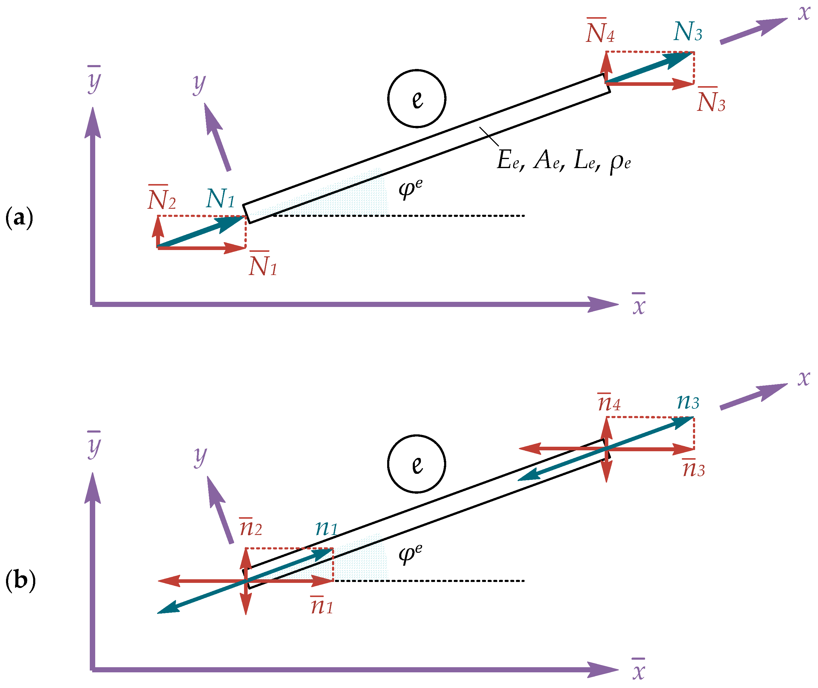
First, we will develop the local stiffness matrix for the gradient truss element. The non-zero generalized nodal forces, denoted by f S i ( i = 1 , 2 , 5 , 6 ), consist of the axial forces f S 1 N 1 and f S 5 N 3 , as well as the double axial forces f S 2 n 1 and f S 6 n 3 (see Figure 3). The corresponding non-zero generalized nodal displacements q i ( i = 1 , 2 ,5,6) include the axial displacements q 1 u 1 and q 5 u 3 , along with their axial strains q 2 u 1 , q 6 u 3 at each end node ( 1 and 2 ) of the truss element, as shown in Figure 2.
To evaluate the truss element stiffness matrix, we derive the exact shape functions, obtained from the solution to the homogeneous Equation (1) [6]:
u x , t = c 1 e x / g + c 2 e x / g + c 3 x + c 4 ,
where c i ( i = 1 , 2 , 3 , 4 ) are integration constants. The space derivatives of the displacement field u x are readily obtained:
u x , t = c 1 g e x / g c 2 g e x / g + c 3 , u x , t = c 1 g 2 e x / g + c 2 g 2 e x / g , u x , t = c 1 g 3 e x / g c 2 g 3 e x / g ,                               u I V x , t = c 1 g 4 e x / g + c 2 g 4 e x / g ,
For the two-node gradient truss element, the displacement field u x , t and v x , t can be expressed as
u x , t = u 1 t ψ 1 x + u 1 t ψ 2 x + u 3 t ψ 5 x + u 3 t ψ 6 x ,
v x , t = u 2 t ψ 1 x + u 2 t ψ 2 x + u 4 t ψ 5 x + u 4 t ψ 6 x ,
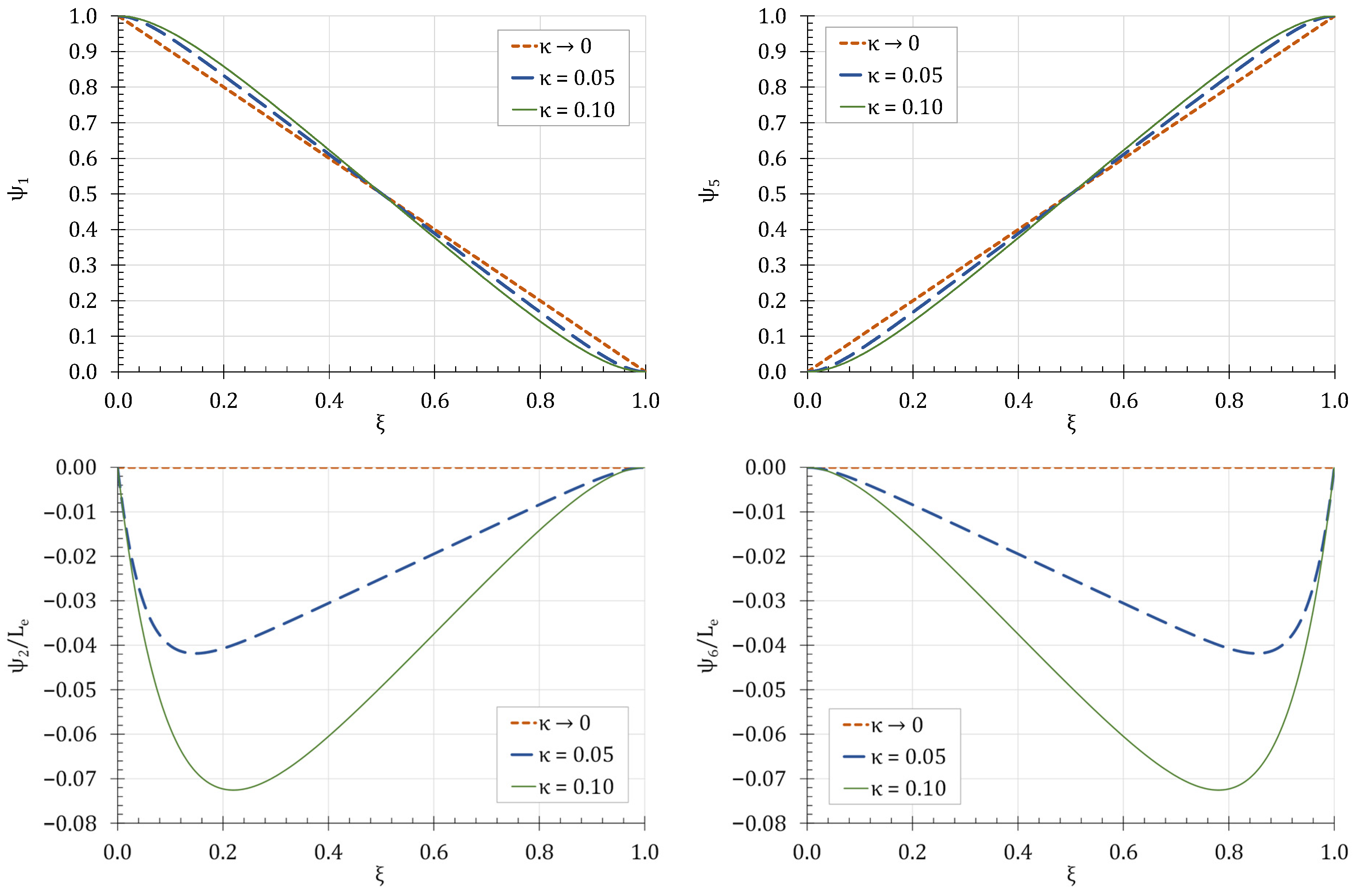
and solving for the unknown constants by satisfying the appropriate boundary conditions we arrive at the following shape functions, using the non-dimensional quantities ξ = x / L e , κ = g / L e :
ψ 1 ξ , κ = e ξ κ e 1 ξ κ κ e 1 κ κ + ξ 1 + κ ξ + 1 e 1 κ 1 2 κ + 1 + 2 κ ψ 2 ξ , κ = 2 L e κ e 1 κ ξ 1 cosh 1 κ + cosh ξ 1 κ ξ + κ sinh 1 κ + sinh ξ 1 κ sinh ξ κ 1 + 2 κ 4 κ e 1 κ + e 2 κ   2 κ 1 ψ 5 ξ , κ = 1 e 1 κ + e 1 ξ κ e ξ κ κ + ξ + e 1 κ ξ 1 + e 1 κ 1 2 κ + 2 κ ψ 6 ξ , κ = 2 L e κ e 1 κ 1 + ξ cosh 1 κ ξ cosh ξ κ κ sinh 1 κ + sinh ξ 1 κ sinh ξ κ 1 + 2 κ 4 κ e 1 κ + e 2 κ   2 κ 1
which satisfy the governing differential equation in an exact way. Figure 4 shows the graphical representation of the shape functions.
Furthermore, the elastic strain energy of the truss element can be expressed as [6]
U = 1 2 0 L e E e A e u x 2 + g 2 u x 2 d x ,
which, after the substitution of Equation (8), is written as
U u 1 , u 1 , u 3 , u 3 = 1 2 0 L e E e A e u 1 ψ 1 x + u 1 ψ 2 x + u 3 ψ 5 x + u 3 ψ 6 x 2 + g 2 u 1 ψ 1 x + u 1 ψ 2 x + u 3 ψ 5 x + u 3 ψ 6 x 2 d x .
Differentiating the elastic strain energy with respect to the generalized nodal displacements q i ( i = 1 , 2 , 3 , 4 ), we derive the generalized nodal elastic forces f S i ( i = 1 , 2 , 5 , 6 ) as
f S i = U q i ,         i = 1 , 2 , 5 , 6 ,
which, with the aid of Equation (12), take the following forms:
f S 1 N 1 = U q 1 = k 11 u 1 + k 12 u 1 + k 15 u 3 + k 16 u 3 , f S 2 n 1 = U q 2 = k 21 u 1 + k 22 u 1 + k 25 u 3 + k 26 u 3 , f S 5 N 3 = U q 5 = k 51 u 1 + k 52 u 1 + k 55 u 3 + k 56 u 3 , f S 6 n 3 = U q 6 = k 61 u 1 + k 62 u 1 + k 65 u 3 + k 66 u 3 ,
where
k i j = 0 L e E e A e ψ i x ψ j x + g 2 ψ i x ψ j x d x ,         i , j = 1 , 2 , 5 , 6 .
In this respect, the exact stiffness matrix of the gradient truss element in local coordinates is given by
k e P T = E e A e 1 L e 2 L e κ tanh 1 2 κ s y m κ coth 1 2 κ 2 κ L e κ csch 1 2 κ 2 κ sinh 1 κ cosh 1 κ 4 κ 2 coth 1 2 κ 0 0 0 0 0 0 0 1 , 1 2 , 1 0 0 [ 1 , 1 ] 2 , 1 L e κ csch 1 2 κ 2 1 κ sinh 1 κ 4 κ 2 coth 1 2 κ 0 0 2 , 1 [ 2 , 2 ] 0 0 0 0 0 0 0 0 0 0 0 0 0 0 0

3.2. Exact Consistent Mass Matrix

In this work, and without restricting the generality, the kinetic energy of the elastic prismatic bar depicted in Figure 1 is defined based on classical elasticity (CE) theory [6,8]. However, to account for gradient effects, an additional characteristic length associated with the continuum microstructure can also be incorporated [12,13].
Thus, the kinetic energy of the truss element can be expressed as
T = 1 2 0 L e ρ e A e u ˙ ( x , t ) 2 + v ˙ ( x , t ) 2 d x ,
which, after the substitution of u ( x , t ) and v ( x , t ) from Equations (8) and (9), results in
T u ˙ 1 , u ˙ 1 , . . , u ˙ 4 = 1 2 0 L e ρ e A e u ˙ 1 ψ 1 x + u ˙ 1 ψ 2 x + u ˙ 3 ψ 5 x + u ˙ 3 ψ 6 x 2                                                                                           + u ˙ 2 ψ 1 x + u ˙ 2 ψ 2 x + u ˙ 4 ψ 5 x + u ˙ 4 ψ 6 x 2 d x .
The inertia forces can be deduced from Equation (5) for i = 1 , 2 , , 8
f I 1 = d d t T q ˙ 1 T q 1 = m 11 u ¨ 1 + m 12 u ¨ 1 + m 15 u ¨ 3 + m 16 u ¨ 3 ,
f I 2 = d d t T q ˙ 2 T q 2 = m 21 u ¨ 1 + m 22 u ¨ 1 + m 25 u ¨ 3 + m 26 u ¨ 3 ,
f I 5 = d d t T q ˙ 5 T q 5 = m 51 u ¨ 1 + m 52 u ¨ 1 + m 55 u ¨ 3 + m 56 u ¨ 3 ,
f I 6 = d d t T q ˙ 6 T q 6 = m 61 u ¨ 1 + m 62 u ¨ 1 + m 65 u ¨ 3 + m 66 u ¨ 3 ,
f I 3 = d d t T q ˙ 3 T q 3 = m 11 u ¨ 2 + m 12 u ¨ 2 + m 15 u ¨ 4 + m 16 u ¨ 4 ,
f I 4 = d d t T q ˙ 4 T q 4 = m 21 u ¨ 2 + m 22 u ¨ 2 + m 25 u ¨ 4 + m 26 u ¨ 4 ,
f I 7 = d d t T q ˙ 7 T q 7 = m 51 u ¨ 2 + m 52 u ¨ 2 + m 55 u ¨ 4 + m 56 u ¨ 4 ,
f I 8 = d d t T q ˙ 8 T q 8 = m 61 u ¨ 2 + m 62 u ¨ 2 + m 65 u ¨ 4 + m 66 u ¨ 4 ,
where
m i j = ρ e A e 0 L e ψ i x ψ j x d x ,         i , j = 1 , 2 , 5 , 6 .
In this respect, the exact consistent mass matrix of the gradient truss element in local coordinates is written as
m e P T = m 11 s y m m 21 m 22 0 0 m 11 0 0 m 21 m 22 m 51 m 52 0 0 m 55 m 61 m 62 0 0 m 65 m 66 0 0 m 51 m 52 0 0 m 55 0 0 m 61 m 62 0 0 m 65 m 66 ,
where
m 11 = ρ e A e L e 6 1 12 κ 2 + 1 3 κ 2 c o s h 1 κ + 3 κ 5 κ 2 1 s i n h 1 κ c o s h 1 2 κ 2 κ   s i n h 1 2 κ 2
m 21 = ρ e A e L e 2 κ c o t h 1 2 κ 8 + 84 κ 2 + 6   c s c h 1 2 κ 2 6 κ 8 + 9   c s c h 1 2 κ 2 24 c o t h 1 2 κ 2 κ 2
m 51 = ρ e A e L e e 1 κ 1 + 12 κ 2 + 1 + 18 κ 2 c o s h 1 κ 6 κ + 5 κ 3 s i n h 1 κ 3 1 + e 1 κ 1 2 κ + 2 κ 2
m 61 = ρ e A e L e 2 κ S 1 + S 2 6 e 1 κ 1 2 κ e 1 κ 1 e 1 κ 2 κ 2 S 1 = 15 e 1 κ κ 2 + 15 e 2 κ κ 2 1 5 e 1 κ 5 e 2 κ 6 κ 15 κ 2 24 κ 3 S 2 = 72 e 1 κ κ 3 72 e 2 κ κ 3 + e 3 κ 24 κ 3 15 κ 2 + 6 κ 1
m 22 = ρ e A e L e 3 e 2 κ κ 2 S 3 + S 4 3 e 1 κ 1 2 1 + e 1 κ 1 2 κ + 2 κ 2 S 3 = 12 + 4 36 κ 2 c o s h 1 κ + 2 + 36 κ 2 c o s h 2 κ S 4 = 6 κ 4 6 κ 2 + 5 + 6 κ 2 c o s h 1 κ s i n h 1 κ
m 52 = ρ e A e L e 2 e 3 2 κ κ S 5 + S 6 3 e 1 κ 1 1 + e 1 κ 1 2 κ + 2 κ 2 S 5 = 5 15 κ 2 c o s h 1 2 κ + 1 + 15 κ 2 c o s h 3 2 κ S 6 = 6 κ 1 8 κ 2 + 2 + 8 κ 2 c o s h 1 κ s i n h 1 2 κ  
m 62 = ρ e A e L e 3 e 2 κ κ 2 S 7 + S 8 3 e 1 κ 1 2 1 + e 1 κ 1 2 κ + 2 κ 2 S 7 = 3 + 72 κ 2 2 7 + 30 κ 2 c o s h 1 κ 1 + 12 κ 2 c o s h 2 κ S 8 = 6 κ 7 6 κ 2 + 2 + 6 κ 2 c o s h 1 κ s i n h 1 κ
m 55 = ρ e A e L e 1 12 κ 2 + 1 3 κ 2 c o s h 1 κ + 3 κ 1 + 5 κ 2 s i n h 1 κ 6 c o s h 1 2 κ 2 κ   s i n h 1 2 κ 2
m 65 = ρ e A e L e 2 e 3 2 κ κ S 9 + S 10 3 e 1 κ 1 1 + e 1 κ 1 2 κ + 2 κ 2 S 9 = 21 κ 2 4 c o s h 1 2 κ 2 + 21 κ 2 c o s h 3 2 κ S 10 = 6 κ 3 s i n h 1 2 κ + 2 s i n h 3 2 κ
m 66 = ρ e A e L e 3 e 2 κ κ 2 S 11 + S 12 3 e 1 κ 1 2 1 + e 1 κ 1 2 κ + 2 κ 2 S 11 = 12 + 4 36 κ 2 c o s h 1 κ + 2 + 36 κ 2 c o s h 2 κ S 12 = 6 κ 4 6 κ 2 + 5 + 6 κ 2 c o s h 1 κ s i n h 1 κ

3.3. Consistent and Lumped Mass Matrices of the Classical Elasticity Theory

To investigate the influence of the material microstructural length parameter g on the mass matrix, both the consistent and lumped mass matrices of the CE theory are employed for the dynamic analysis.
The consistent mass matrix in CE theory is expressed as
m e C E , c o n = ρ e A e L e 6 2 0 0 0 1 0 0 0 0 0 0 0 0 0 0 0 0 0 2 0 0 0 1 0 0 0 0 0 0 0 0 0 1 0 0 0 2 0 0 0 0 0 0 0 0 0 0 0 0 0 1 0 0 0 2 0 0 0 0 0 0 0 0 0 ,
while the corresponding lumped mass matrix simplifies to
m e C E , l u m = ρ e A e L e 2 1 0 0 0 0 0 0 0 0 0 0 0 0 0 0 0 0 0 1 0 0 0 0 0 0 0 0 0 0 0 0 0 0 0 0 0 1 0 0 0 0 0 0 0 0 0 0 0 0 0 0 0 0 0 1 0 0 0 0 0 0 0 0 0 .

3.4. Transformation Matrix

To incorporate the orientation of each element, a transformation matrix is employed. The direction cosines, cos φ e and sin φ e , facilitate the conversion of local generalized nodal forces, f S e , into the global coordinate system, f ¯ S e , as
N 1 n 1 N 2 n 2 N 3 n 3 N 4 n 4 = cos φ e 0 sin φ e 0 0 0 0 0 0 cos φ e 0 sin φ e 0 0 0 0 sin φ e 0 cos φ e 0 0 0 0 0 0 sin φ e 0 cos φ e 0 0 0 0 0 0 0 0 cos φ e 0 sin φ e 0 0 0 0 0 0 cos φ e 0 sin φ e 0 0 0 0 sin φ e 0 cos φ e 0 0 0 0 0 0 sin φ e 0 cos φ e N ¯ 1 n ¯ 1 N ¯ 2 n ¯ 2 N ¯ 3 n ¯ 3 N ¯ 4 n ¯ 4 ,
or
f S e = R e P T f ¯ S e ,
where
R e P T = cos φ e 0 sin φ e 0 0 0 0 0 0 cos φ e 0 sin φ e 0 0 0 0 sin φ e 0 cos φ e 0 0 0 0 0 0 sin φ e 0 cos φ e 0 0 0 0 0 0 0 0 cos φ e 0 sin φ e 0 0 0 0 0 0 cos φ e 0 sin φ e 0 0 0 0 sin φ e 0 cos φ e 0 0 0 0 0 0 sin φ e 0 cos φ e ,
is the transformation matrix of the gradient truss element.

4. Numerical Examples

Based on the numerical procedure outlined in the previous section, a MATHEMATICA™ code was developed to obtain numerical results that demonstrate the proposed method’s applicability, effectiveness, and accuracy.

4.1. Axially Loaded Bar

The first example considers a gradient bar with a length L = 5   m and a circular cross-section of diameter D = 10   mm . The bar is supported at node 1 by a pin and at node 2 by a roller, with an axial force N L = P = 100   kN applied (see Figure 5). The remaining boundary conditions are defined as u 0 = u 0 = n L = 0 , while the material properties are specified as follows: E = 210   GPa , ρ = 7850   kg / m . A static analysis is first conducted to determine the displacement u ( L ) and strain u ( L ) at node 2 using one and four gradient truss elements. The results, shown in Table 1 for different values of the microstructural length g , indicate that a single element is sufficient to accurately capture the static response of the gradient bar using the proposed SGE theory. For comparison, the displacement u ( L ) from the CE theory, obtained with a FE formulation using one element and linear interpolation, also compares well with the SGE theory results for g = 0.001   m . Additionally, as the material’s length g increases, the displacement u ( L ) decreases, indicating a stiffening effect in the bar that leads to a 9.98% reduction, relative to the CE solution, when g = 0.5   m . This stiffening behavior also applies to the strain u L , although to a lesser extent.
The dynamic response of the same gradient bar was then investigated, and the first four natural frequencies, ω n ( rad / s ) , for g = 0.2   m are presented in Table 2. Frequency convergence occurs rapidly as the number of elements N increases; notably, the first two frequencies yield accurate results with just five elements, while convergence for all four frequencies is achieved with ten elements.
To examine the influence of the material’s microstructural length g on the bar’s natural frequencies the first four natural frequencies, ω n ( rad / s ) , are depicted in Table 3 for various values of g , using 10 elements. As g increases, the stiffening behavior becomes more pronounced, resulting in an increase in ω n . This stiffening effect intensifies at higher frequencies.
Furthermore, to examine the influence of the material microstructural length g on the mass matrix, both the consistent and lumped mass matrices of the CE theory are utilized for g = 0.001   m . For this very small value of g , the convergence rate decreases, requiring more elements to accurately capture the dynamic response. Table 4 shows the first four natural frequencies, ω n ( rad / s ) , derived from these analyses using 15 elements, along with results from an FE formulation with lumped mass matrix employing 4 and 12 elements. The consistent matrices based on both the SGE and CE theories yield very similar results, a trend that is also observed when comparing the CE lumped mass matrix to the results from the FE formulation.

4.2. Statically Determinate Gradient Truss

In this example, we analyze a planar gradient truss (see Figure 6). Each truss member has a circular cross-section with a diameter of D = 20   mm and material properties of E = 210   GPa , ρ = 7850   kg / m . The truss is supported by pins at nodes 1 and 3 , where all geometric boundary conditions are zero, while nodes 2 and 4 have all their degrees of freedom (DoF) unrestrained and free to move. To begin with, we perform a static analysis with P = 100   kN , and the resulting displacements and strains at various DoF are summarized in Table 5 for different values of the microstructural length g . For comparison, the displacements derived from CE theory, obtained with a FE formulation, also show excellent agreement with the SGE theory results for g = 0.001   m . Overall, as g increases, displacements decrease, reflecting the truss’s stiffening behavior. Specifically, u ¯ 5 exhibits a reduction of 9.52% relative to the CE solution, when g = 0.5   m , while the corresponding reductions in u ¯ 7 and u ¯ 12 are of 15.90% and 15.51%, respectively. However, this stiffening effect has a negligible influence on strains, as seen in u ¯ 6 and u ¯ 16 .
The dynamic response of the gradient truss was then analyzed, and the first four natural frequencies, ω n   ( r a d / s ) , for various values of g are presented in Table 6. As g increases, ω n generally rises; however, this effect is less pronounced at lower frequencies. For example, when g = 0.5   m , ω 1 and ω 2 show an approximate 5% increase relative to the CE solution. In contrast, ω 3 increases by 12.2%, while ω 4 displays only a negligible change.
To further assess the impact of the material microstructural length g on the mass matrix, both consistent and lumped mass matrices based on the CE theory were utilized. Table 7 and Table 8 present the first four natural frequencies, ω n , obtained from these analyses for g = 0.001   m and g = 0.5   m , respectively, along with results from an FE formulation. The results indicate that g has a minimal effect on the mass matrix. The consistent matrices derived from both the SGE and CE theories yield closely related results, a trend also observed when comparing the CE lumped mass matrix with the FE formulation results (see Table 7). However, consistent mass matrices consistently produce higher frequencies than lumped mass matrices (see Table 8).

5. Conclusions

This paper investigates the static and dynamic responses of bars and planar trusses using a simplified, engineering-oriented strain gradient theory. To achieve this, a two-node bar element with four degrees of freedom per node—capturing axial and transverse displacements as well as strains—was developed. The displacement function was derived using the exact solution to the homogeneous governing equation. The main conclusions are summarized as follows:
  • The static analysis of the bar indicates that a single element is sufficient to accurately capture the response of the gradient bar using the proposed SGE theory. Furthermore, as the material’s characteristic length g increases, the displacement u decreases, reflecting a stiffening effect. This behavior also applies to the strain u , although to a lesser extent.
  • Dynamic analysis reveals that g significantly influences the bar’s natural frequencies ω n . Specifically, as g increases, the stiffening effect becomes more pronounced, resulting in higher values of ω n . This effect intensifies at higher frequencies.
  • For the frame, both static and dynamic analyses confirm the same stiffening effect. However, its influence on strains remains negligible.
  • The results from the dynamic analysis of the frame indicate that g has a minimal effect on the mass matrix. The consistent mass matrices derived from both the SGE and CE theories yield closely related results. A similar trend is observed when comparing the CE lumped mass matrix with the FE formulation. Notably, consistent mass matrices consistently produce higher frequencies than lumped mass matrices.

Author Contributions

Conceptualization, G.C.T. and A.E.G.; methodology, G.C.T. and A.E.G.; software, G.C.T. and A.E.C.; validation, A.E.C. and P.T.; writing—original draft preparation, G.C.T.; writing—review and editing, A.E.G., A.E.C. and P.T. All authors have read and agreed to the published version of the manuscript.

Funding

This research received no external funding.

Data Availability Statement

All data used to support the findings of this study are available from the corresponding author upon request.

Conflicts of Interest

The authors declare no conflicts of interest.

References

  1. Ben-Amoz, M. A Dynamic Theory for Composite Materials. Z. Angew. Math. Phys. ZAMP 1976, 27, 83–99. [Google Scholar] [CrossRef]
  2. Kordolemis, A.; Aravas, N.; Giannakopoulos, A.E. Pretwisted Beams in Axial Tension and Torsion: Analogy with Dipolar Gradient Elasticity and Applications to Textile Materials. J. Eng. Mech. 2015, 141, 04015036. [Google Scholar] [CrossRef]
  3. Lakes, R. Materials with Structural Hierarchy. Nature 1993, 361, 511–515. [Google Scholar] [CrossRef]
  4. Giannakopoulos, A.E.; Knisovitis, C.; Zisis, T.; Tsiatas, G.C. Fiber Pull-out in a Flexoelectric Material. Mater. Today Proc. 2023, 93, 646–657. [Google Scholar] [CrossRef]
  5. Sulem, J.; Vardoulakis, I.G. Bifurcation Analysis in Geomechanics. In Bifurcation Analysis in Geomechanics; CRC Press: Boca Raton, FL, USA, 1995. [Google Scholar] [CrossRef]
  6. Tsepoura, K.G.; Papargyri-Beskou, S.; Polyzos, D.; Beskos, D.E. Static and Dynamic Analysis of a Gradient-Elastic Bar in Tension. Arch. Appl. Mech. 2002, 72, 483–497. [Google Scholar] [CrossRef]
  7. Papargyri-Beskou, S.; Tsepoura, K.G.; Polyzos, D.; Beskos, D.E. Bending and Stability Analysis of Gradient Elastic Beams. Int. J. Solids Struct. 2003, 40, 385–400. [Google Scholar] [CrossRef]
  8. Papargyri-Beskou, S.; Polyzos, D.; Beskos, D.E. Dynamic Analysis of Gradient Elastic Flexural Beams. Struct. Eng. Mech. 2003, 15, 705–716. [Google Scholar] [CrossRef]
  9. Giannakopoulos, A.E.; Stamoulis, K. Structural Analysis of Gradient Elastic Components. Int. J. Solids Struct. 2007, 44, 3440–3451. [Google Scholar] [CrossRef]
  10. Triantafyllou, A.; Giannakopoulos, A.E. Structural Analysis Using a Dipolar Elastic Timoshenko Beam. Eur. J. Mech.-A/Solids 2013, 39, 218–228. [Google Scholar] [CrossRef]
  11. Tsamasphyros, G.I.; Markolefas, S.; Tsouvalas, D.A. Convergence and Performance of the H- and p-Extensions with Mixed Finite Element C0-Continuity Formulations, for Tension and Buckling of a Gradient Elastic Beam. Int. J. Solids Struct. 2007, 44, 5056–5074. [Google Scholar] [CrossRef]
  12. Filopoulos, S.P.; Papathanasiou, T.K.; Markolefas, S.I.; Tsamasphyros, G.J. Dynamic Finite Element Analysis of a Gradient Elastic Bar with Micro-Inertia. Comput. Mech. 2010, 45, 311–319. [Google Scholar] [CrossRef]
  13. Georgiadis, H.G.; Vardoulakis, I.; Velgaki, E.G. Dispersive Rayleigh-Wave Propagation in Microstructured Solids Characterized by Dipolar Gradient Elasticity. J. Elast. 2004, 74, 17–45. [Google Scholar] [CrossRef]
  14. Pegios, I.P.; Papargyri-Beskou, S.; Beskos, D.E. Finite Element Static and Stability Analysis of Gradient Elastic Beam Structures. Acta Mech. 2015, 226, 745–768. [Google Scholar] [CrossRef]
  15. Pegios, I.P.; Hatzigeorgiou, G.D. Finite Element Free and Forced Vibration Analysis of Gradient Elastic Beam Structures. Acta Mech. 2018, 229, 4817–4830. [Google Scholar] [CrossRef]
  16. Asiminas, E.L.; Koumousis, V.K. A Beam Finite Element Based on Gradient Elasticity. In Proceedings of the 10th HSTAM International Congress on Mechanics, Chania, Greece, 25–27 May 2013; Beskos, D.E., Stavroulakis, G.E., Eds.; Technical University of Crete Press: Chania, Greece, 2013; p. 123. [Google Scholar]
  17. Giannakopoulos, A.E.; Amanatidou, E.; Aravas, N. A Reciprocity Theorem in Linear Gradient Elasticity and the Corresponding Saint-Venant Principle. Int. J. Solids Struct. 2006, 43, 3875–3894. [Google Scholar] [CrossRef]
  18. Tsiatas, G.C. A New Efficient Method to Evaluate Exact Stiffness and Mass Matrices of Non-Uniform Beams Resting on an Elastic Foundation. Arch. Appl. Mech. 2014, 84, 615–623. [Google Scholar] [CrossRef]
Figure 1. Geometry and loading of a straight prismatic bar.
Buildings 14 04031 g001
Figure 2. Degrees of freedom of a plane gradient truss element.
Buildings 14 04031 g002
Figure 3. Generalized nodal forces of a gradient truss element: (a) Axial forces and (b) double axial forces.
Buildings 14 04031 g003
Figure 4. Shape functions of the gradient truss element ( ξ = x / L e , κ = g / L e ).
Buildings 14 04031 g004
Figure 5. Geometry and loading of the gradient bar of Example 4.1.
Buildings 14 04031 g005
Figure 6. Geometry and loading of the gradient truss of Example 4.2.
Buildings 14 04031 g006
Table 1. Displacement u ( L ) (m) and strain u ( L ) (rad) at node 2 of the gradient bar of Example 4.1.
g   ( m ) u L
SGE-N = 1
u L
SGE-N = 4
u L
FEM-N = 1
u ( L )
SGE-N = 1
u ( L )
SGE-N = 4
0.0010.03030920.03030920.0303150.006063050.00606305
0.10.02970890.0297089-0.006063050.00606305
0.20.02910260.0291026-0.006063050.00606305
0.30.02849630.0284963-0.006063040.00606304
0.40.02789000.0278900-0.006063000.00606300
0.50.02728370.0272837-0.006062490.00606249
Table 2. First four natural frequencies ω n ( rad / s ) of the gradient bar of Example 4.1 for g = 0.2   m .
nSGE-N = 1SGE-N = 3SGE-N = 5SGE-N = 7SGE-N = 10SGE-N = 15
11835.461705.151697.661696.301695.841695.70
241,472.25408.715214.885177.505164.705160.91
3-9588.469097.558922.848860.538841.76
4-20,018.513,546.213,103.412,922.012,865.6
Table 3. First four natural frequencies ω n ( rad / s ) of the gradient bar of Example 4.1 ( N = 10 ) for various values of the microstructural length g   ( m ) .
ng = 0.1g = 0.2g = 0.3g = 0.4g = 0.5
11659.311695.841735.341777.431821.74
25008.125164.705364.325594.305845.76
38447.838860.539444.8910,142.010,921.5
412,039.912,922.014,220.915,780.617,529.6
Table 4. First four natural frequencies ω n ( rad / s ) of the gradient bar of Example 4.1 for g = 0.001   m ( N = 15 ).
nth Mode SGE-N = 15CE-N = 15
Consistent
CE-N = 15
Lumped
FEM-N = 4
Lumped
FEM-N = 12
Lumped
11625.951625.971624.491614.571623.83
24895.384896.044855.944597.914843.71
38217.568220.648034.986881.257980.71
411,628.1011,636.511,127.28116.9910,981.16
Table 5. Displacements (m) and strains (rad) at various DoF of the gradient truss of Example 4.2 for various values of the microstructural length g   ( m ) .
FEMg = 0.001g = 0.1g = 0.2g = 0.3g = 0.4g = 0.5
u ¯ 5 −0.006821−0.006820−0.006703−0.006585−0.006466−0.006348−0.006228
u ¯ 6 -−0.003365−0.003365−0.003365−0.003365−0.003363−0.003356
u ¯ 7 −0.028799−0.028792−0.028010−0.027220−0.026430−0.025640−0.024848
u ¯ 15 −0.034863−0.034853−0.033927−0.032992−0.032057−0.031121−0.030182
u ¯ 16 −0.001516−0.001516−0.001516−0.001516−0.001516−0.001515
Table 6. First four natural frequencies ω n ( rad / s ) of the gradient truss of Example 4.2 for various values of the microstructural length g   ( m ) .
nth Mode g = 0.001g = 0.1g = 0.2g = 0.3g = 0.4g = 0.5
1577.911582.026587.14593.192600.124607.883
21582.531592.441606.131623.961646.311673.55
32084.532109.472149.252202.062226.002338.66
42518.522512.242514.812524.152538.252555.29
Table 7. First four natural frequencies ω n ( rad / s ) of the gradient truss of Example 4.2 for g = 0.001   m .
nth
Mode
SGE
Consistent
CE
Consistent
CE
Lumped
FEM
Lumped
1577.911577.952518.707518.669
21582.531582.801347.671347.44
32084.532084.731596.441596.27
42518.522518.711821.861821.93
Table 8. First four natural frequencies ω n ( rad / s ) of the gradient truss of Example 4.2 for g = 0.5   m .
nth
Mode
SGE
Consistent
CE
Consistent
CE
Lumped
1607.883620.854557.089
21673.551789.231536.44
32338.662301.061748.52
42555.292548.691842.55
Disclaimer/Publisher’s Note: The statements, opinions and data contained in all publications are solely those of the individual author(s) and contributor(s) and not of MDPI and/or the editor(s). MDPI and/or the editor(s) disclaim responsibility for any injury to people or property resulting from any ideas, methods, instructions or products referred to in the content.