
Cyclic Loading Test Conducted on the Bottom Joints of a Hybrid Precast Utility Tunnel Composed of Double-Skin Sidewalls and a Precast Bottom Slab

Abstract
:1. Introduction
- (a)
- Hybrid precast utility tunnels possess excellent structural integrity and waterproofing performance, making them convenient for construction with relatively low technical requirements. This tunnel is a type of prefabricated concrete utility tunnel suitable for large-scale promotion.
- (b)
- Currently, the primary method of connecting the components of hybrid precast utility tunnels is through casting concrete in the core areas, which presents challenges in terms of on-site construction convenience.
- (c)
- The existing codes still fail to account for the seismic design provisions of hybrid precast UTs.
2. Experimental Section
2.1. Specimen
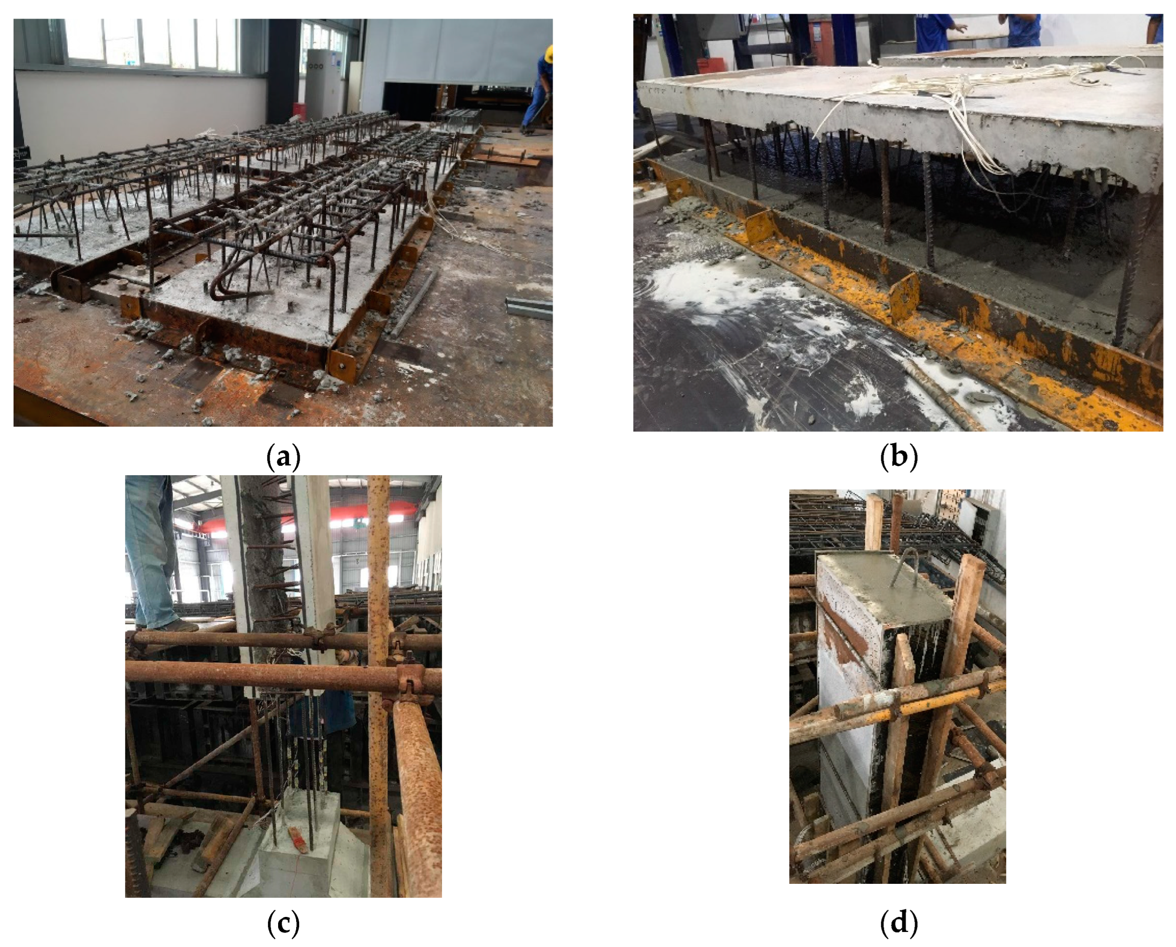
2.2. Construction Method
- (a)
- Bind the reinforcing bar cage of the double-skin sidewalls, insert the reinforcing bar into the mold, pour the outside slab of the sidewall, and reduce the concrete in the overlapping area of the additional reinforcing bar from 80 mm to 60 mm. Reserve space for the additional reinforcing bar, and then send it to the curing kiln for curing, as shown in Figure 3a.
- (b)
- When the strength of the concrete reaches the hoisting requirements, turn over the composite sidewalls and pour the inside slab of the sidewall, as shown in Figure 3b.
- (c)
- Hoist the composite sidewall, insert the additional reinforcement bars reserved for the CIP bottom slab into the cavity of the double-skin sidewall, and ensure that the inserted reinforcement adheres closely to the inner surface of the precast sidewall to limit the height of the section. When assembling, pay attention to leveling using a spirit level to ensure that the upper sidewall and the lower CIP bottom slab are aligned, as shown in Figure 3c.
- (d)
- After positioning, assembling, and fixing the composite sidewall and the CIP bottom slab, support the side formwork of the composite sidewall, use concrete to pour the middle mixed layer of the sidewall, and use vibrating rods for vibration and compaction, as shown in Figure 3d.
2.3. Material Properties
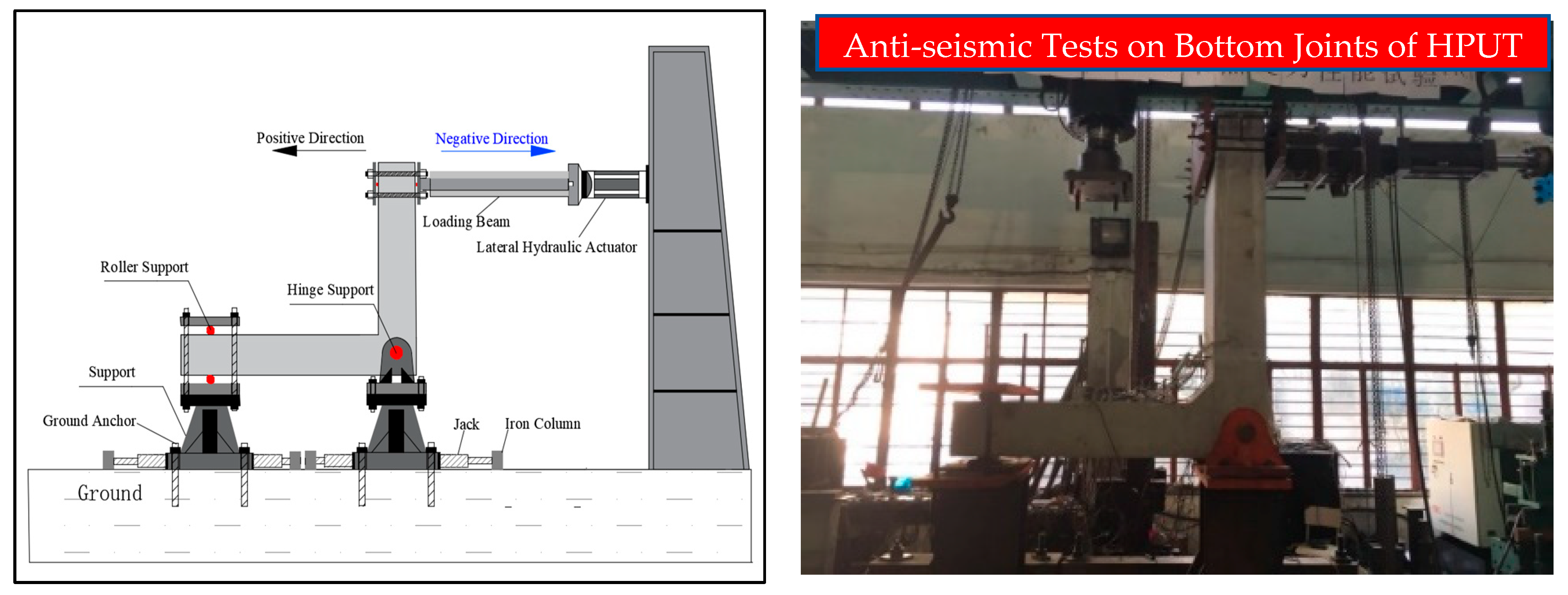
2.4. Test Setup
2.5. Instrumentation
3. Result Analysis and Comparison
3.1. Overall Response and Failure Pattern
- (1)
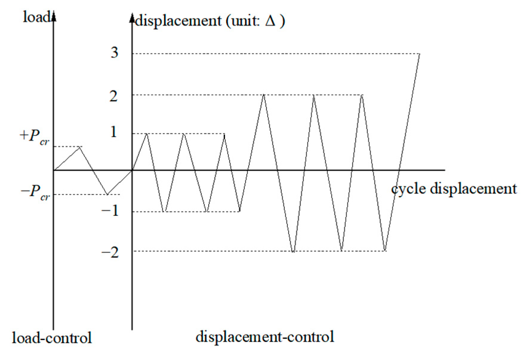
- Cracking stage. When the load reached the peak load of 0.37~0.57 times, the specimens cracked. The cracking loads of the PUT and RUT specimens without haunches were 30 kN and 25 kN, respectively, and the cracks were located on the lower surface of the sidewall joint and the junction between the lower end of the sidewall and the bottom slab, respectively. The cracking loads of the PUT-H and RUT-H specimens with haunches were 15 kN and 40 kN, respectively, and the cracks were located on the sidewall joint’s lower surface and the sidewall’s tip haunch, respectively. All the initial cracks were flexural cracks.
- (2)
- Yield stage. When the load reached 0.80~0.87 times the peak load, the steel bar began to yield gradually. The precast specimens PUT and PUT-H began to yield to tension (the steel bar strain was about 2350 με), and the CIP specimens RUT and RUT-H were at the lower end of the sidewall near the tip of the haunch and the sidewall, respectively. The vertical steel bar at the junction of the lower end and the bottom slab began to yield to tension (the steel bar strain was about 2300 με). With the increase in the load, the cracks of the PUT specimen were mainly concentrated in the joint sizing layer and the junction of the lower end of the sidewall and the bottom slab, all of which constituted horizontal bending cracks, and vertical bending cracks appeared at the junction of the bottom slab and the sidewall. The cracks of the RUT specimen were mainly distributed at the junction of the lower end of the sidewall and the bottom slab and gradually developed from the bottom to the top, and only a few vertical bending cracks appeared at the junction of the bottom slab and the sidewall. The cracks of PUT-H were mainly concentrated in the grouting layer of the joint, and only a few cracks appeared in other parts of the lower end of the sidewall, while no cracks were found in the bottom slab. The cracks of the RUT-H specimen were mainly distributed in the sidewall near the haunch variable cross-section area and gradually developed from the bottom to the top, and no cracks were found in the bottom slab.
- (3)
- Peak stage. Regarding the haunch-free specimens, PUT reached peak loads of 146.50 kN and 60.89 kN at forward and reverse displacement angles of 2.91% and 2.00%, while RUT reached peak loads of 148.35 kN and 60.89 kN at forward and reverse displacement angles of 3.52% and 1.99%. Regarding the specimens with haunches, PUT-H reached peak loads of 146.50 kN and 97.67 kN at forward and reverse displacement angles of 3.52% and 2.92%; RUT-H reached peak loads of 174.84 kN at forward and reverse displacement angles of 2.94% and 2.99%, and 90.11 kN was also reached. At this stage, the cracks in the specimen are basically uniform, and the horizontal bending cracks on both sides of the sidewall are symmetrically distributed; additionally, the cracks gradually widen and extend, and the concrete protective layer on both sides of the sidewall begins to be crushed and spalled. There were no obvious cracks between the outer blade of the sidewalls of the two precast specimens and the post-cast composite layer, indicating that the new and old concretes of the double-sided superimposed sidewalls of the precast specimens had good bonding performance.
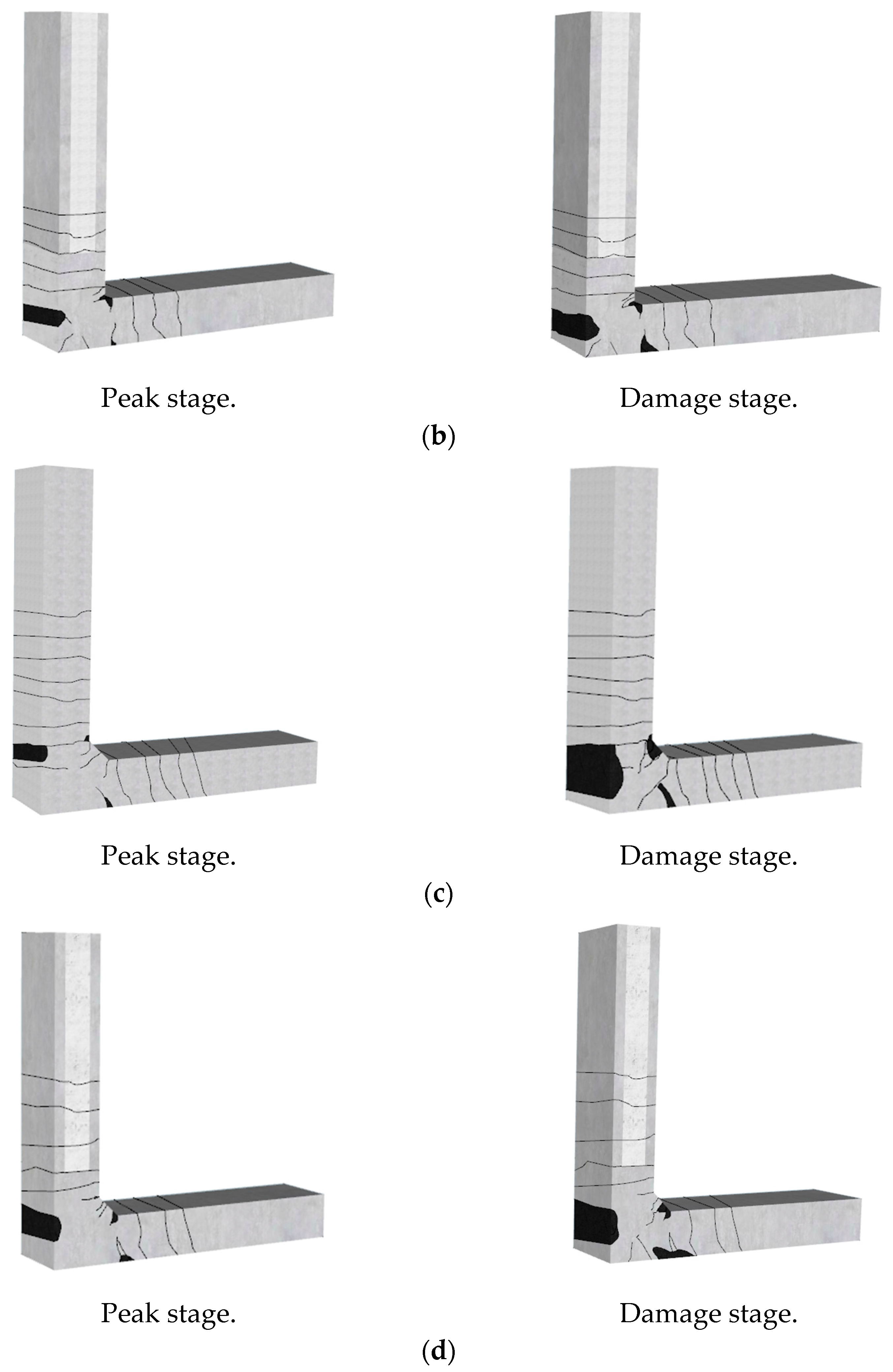
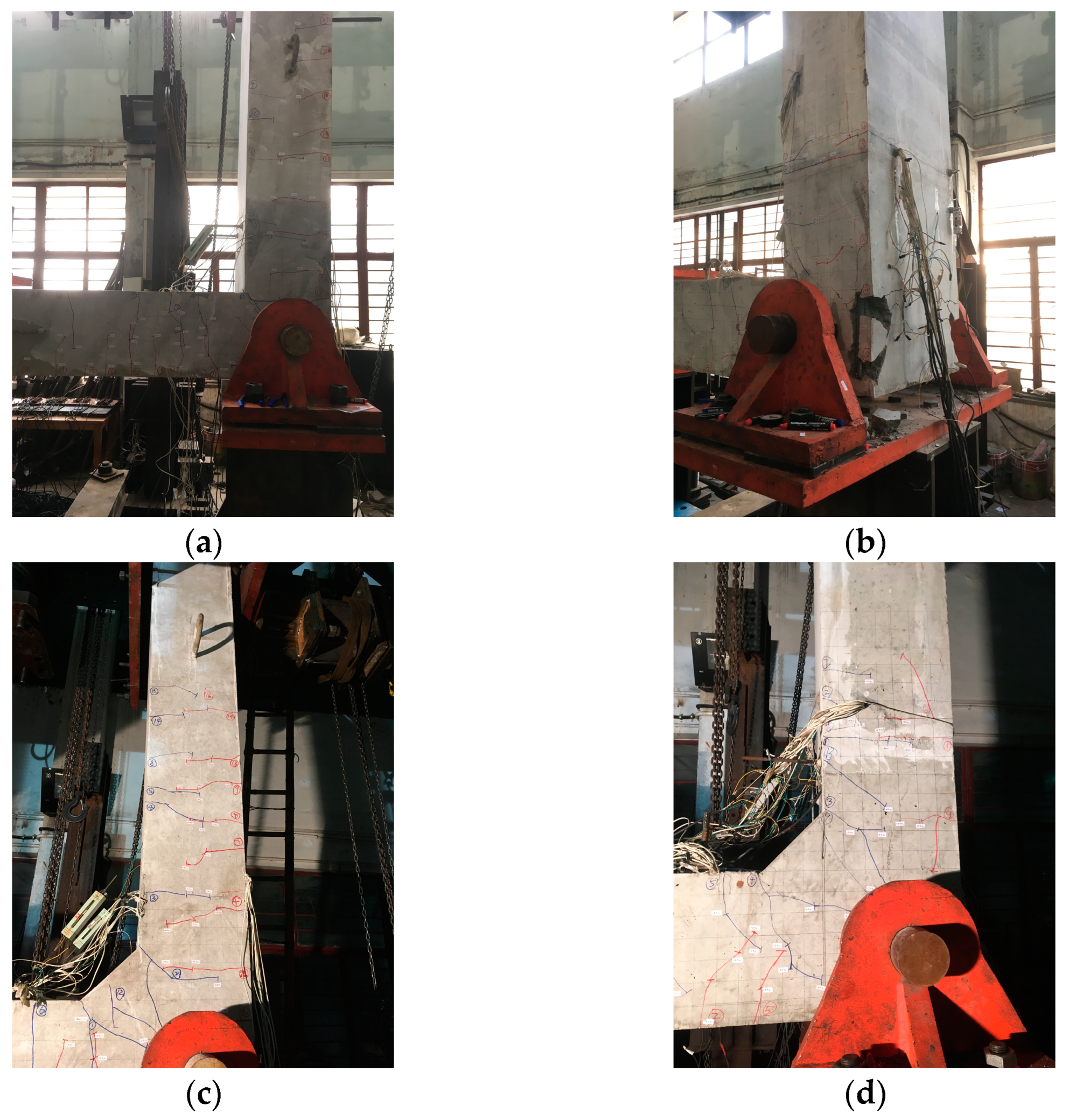
- (4)
- Damage stage. After reaching the peak load, the specimen entered the failure stage. As shown in Figure 6, the final failure modes of the four specimens are all flexural failures. The failure positions of PUT and RUT were located at the end of the bottom slab, and the failure positions of PUT-H and RUT-H were located at the tip of the haunch at the end of the bottom slab. The type of flexion was exposed or compression flexion that bulged outward, and part of the longitudinal reinforcement was pulled off. Among the types of damage observed, the damage on the outer side of the lower end of the sidewall of RUT-H is also obvious. No obvious cracks were seen in the joint core area of all the specimens during the loading period, and the specimens remained intact until failure, meeting the design requirements of strong joints and weak members.
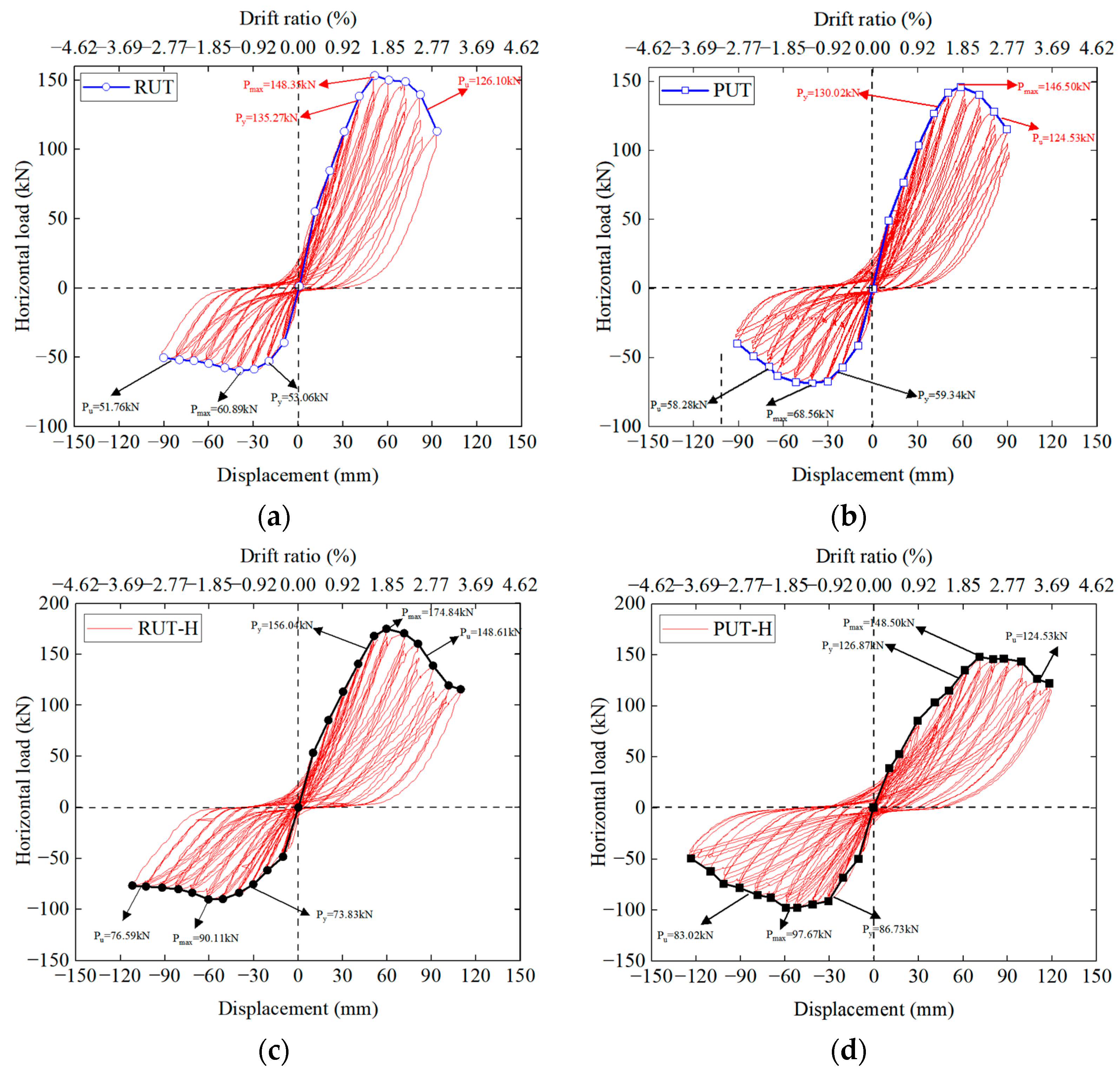
3.2. Hysteresis Response
- (1)
- Before the specimens crack, the horizontal load and displacement are approximately linear, and their structures are basically in the elastic stage, and their residual deformation and damage are slight. With the increase in displacement, the structures undergo plastic deformation, residual deformation increases gradually, and the enclosing area of the hysteresis curve also increases. In the later loading stage, the hysteresis curve appears to reflect a pinch effect due to the steel bar’s yielding and the concrete’s spalling.
- (2)
- At the same level of displacement, the load peak value of the first cycle is often higher than the latter two times, mainly due to the structure’s damage accumulation and strength degradation. After the horizontal load reaches the peak value, the bearing capacity of the specimen decreases slowly with increasing horizontal displacement, showing good ductility.
- (3)
- The shapes and number of hysteresis loops of the CIP specimen and the precast specimen are similar, indicating that the energy dissipation performance and deformation capacity of the HPUT are similar to those of the comparative specimen. Throughout the loading process, the hysteresis loop shape transitioned gradually from a plum shape to an inverse S shape, and the energy dissipation capacity gradually decreased. This was mainly due to a large amount of spalling of the outer concrete and slippage between the outer longitudinal reinforcement and the concrete at the corner of the joint in the later loading stage.
- (4)
- Comparing the specimens with and without haunches, the shapes of the hysteresis loops are similar. The area enclosed by the hysteresis loop for the specimen with the haunch is more significant than that for the specimen without the haunch, and the energy dissipation performance is relatively good. The confinement of the concrete in the haunches reduced the damage to the sidewalls and slabs.
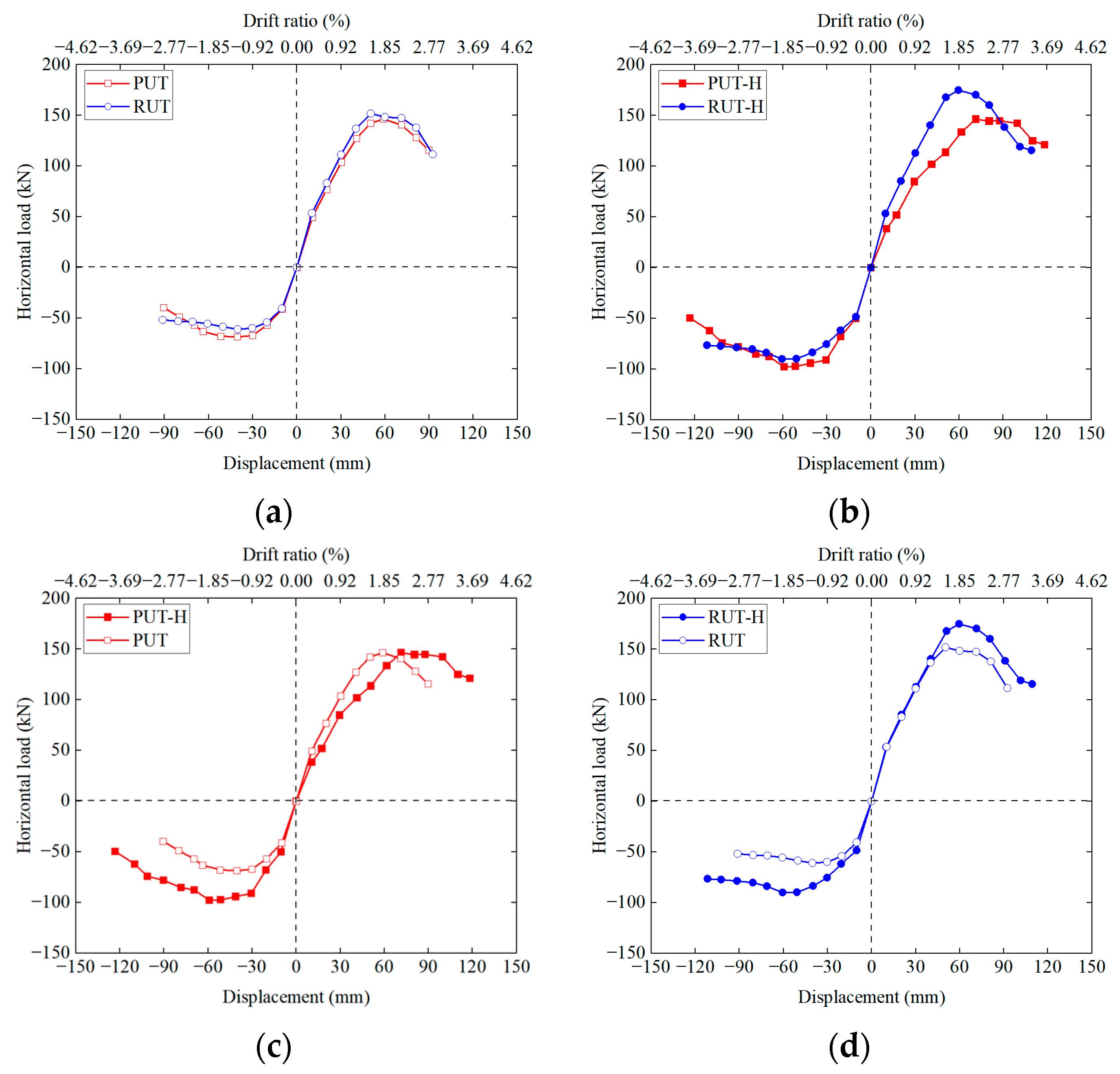
3.3. Response Envelopes
- (1)
- The skeleton curves of the four specimens have four characteristic points: cracking, yielding, reaching the peak value, and failure. The stress process of the structure can be divided into four stages: before cracking, when the load and displacement exhibit linear relationships; after cracking to before yielding, when the stiffness of the specimen decreases rapidly; after yielding to before reaching the peak point, when the skeleton curve becomes gentle; and after reaching the peak point, when the tangential stiffness of the specimen is negative, and its bearing capacity decreases slowly, showing good ductility.
- (2)
- The positive bearing capacity of each specimen was more significant than that in the negative direction. This can be attributed to the additional reinforcement installed at the corner on the positive side of the specimens, enhancing the positive load-bearing capacity of the joint. The positive bearing capacity of PUT is 1.35% lower than that of RUT, and the negative bearing capacity is 11.2% higher than that of PUT. The average bearing capacity of the PUT specimen is 2.7% higher than that of RUT. The positive bearing capacity of the precast specimen PUT-H is 16.2% lower than that of the CIP comparative specimen RUT-H, and the negative bearing capacity is 9.3% higher than that of the CIP comparative specimen. The average bearing capacity of the PUT-H specimen is 8.5% lower than that of RUT-H. It can be seen that the bearing capacities of the HPUT and the CIP specimen are similar.
- (3)
- The positive bearing capacity of the specimens PUT and RUT without haunches are 15.15%–1.35% lower than those with haunches (PUT-H and RUT-H). However, the negative bearing capacities of the specimens PUT and RUT without haunches are 29.80–32.4% lower than those with haunches. It can be seen that the reinforcement and concrete at the haunches have a stronger restraint effect when the exterior joints are subjected to a negative force.
- (4)
- The positive bearing capacity of the precast specimen PUT-H is 16.2% lower than that of the CIP comparative specimen. This difference may be attributed to the distinct failure sections of the precast and CIP specimens, with the CIP specimen failing at the upper part of the haunch, while the precast specimen failed at the lower part of the haunch.
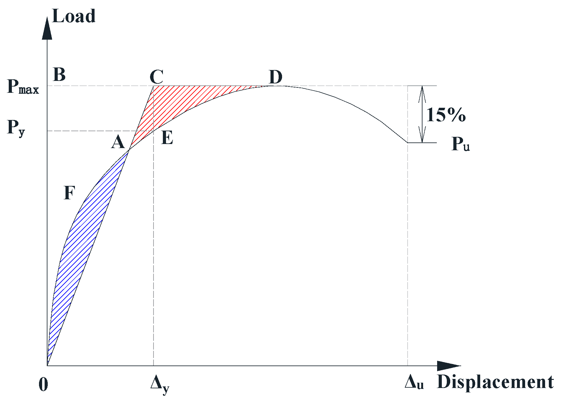
3.4. Displacement Ductility and Deformability
- (1)
- The average ductility values of RUT, PUT, RUT-H, and PUT-H are 3.36, 2.98, 2.55, and 2.46, respectively. The ductility coefficients of both precast specimens are lower than this value for the CIP structure by −11.3% and −3.53%, respectively. The main reason for this could be the overlap of reinforcement in the core area of the precast elements, which, to some extent, increases the structural reinforcement ratio, enhances structural stiffness, and, consequently, affects the ductility coefficient of the structure.
- (2)
- The ductility of the precast specimen without a haunch is 11.3% lower than that of the CIP control specimen, while the ductility of the precast specimens with a haunch is 3.53% lower than that of the CIP comparative specimens. The main reason for this is that the haunch increases structural stiffness, thereby reducing the impact of the overlap zone reinforcement ratio of the precast element on the stiffness.
- (3)
- The impact of the haunch on the ductility coefficient is quite evident, causing a reduction of 17.40% in the ductility of the precast specimen and a reduction of 24.10% in the ductility of the CIP specimen.
- (4)
- The negative ductility of all the specimens is more pronounced than the positive ductility. This can be attributed to the significant peeling of material on the outer concrete at the corners of the joints during the later loading stages, resulting in bond slip between the external longitudinal reinforcement and the concrete, leading to a rapid decrease in bearing capacity.
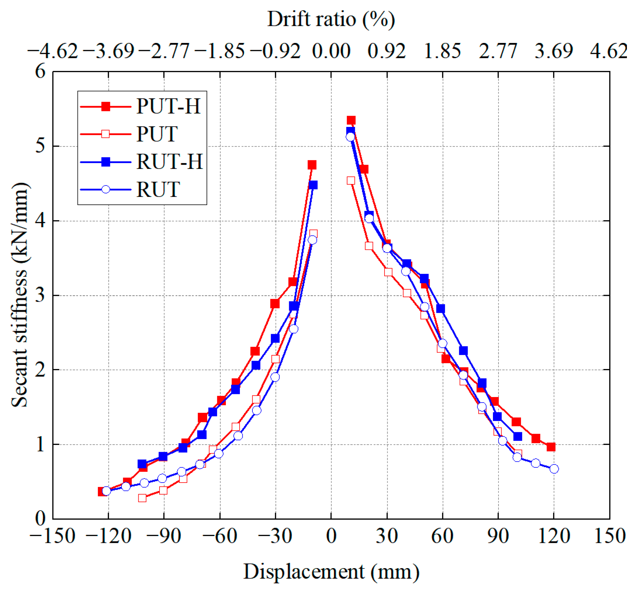
3.5. Deformability Stiffness Degradation
- (1)
- The stiffness degradation laws of the four specimens are consistent, and the stiffness decreases rapidly in the early loading stage; with the increase in lateral movement, the decreasing stiffness trend slows. This indicates that the specimens’ stiffness degradation is mainly concentrated in the early loading stage.
- (2)
- At all levels of displacement, the stiffnesses of the precast joint and the CIP comparison specimen are the same, indicating that the precast joint and the CIP comparison specimen show similar stiffness degradation characteristics.
- (3)
- In the early loading stage, the stiffness of the specimens with and without a haunch is basically the same; in the later loading stage, the specimen without a haunch degrades faster.
3.6. Energy Dissipation Capacity
- (1)
- When the load is small, the specimen is in the elastic stage and consumes less energy. With the increase in loading, the specimen enters the elastic-plastic stage, the steel bar gradually yields, concrete damage accumulates, and the energy dissipation capacity of each specimen increases continuously.
- (2)
- Compared with the CIP specimens, the energy dissipation capacities of PUT and RUT are comparable. The energy dissipation performance of PUT-H is higher than that of RUT-H. This indicates that the HPUT has an optimized local variable cross-section with an L-shaped reinforced connection, giving full play to its energy dissipation effect.
- (3)
- Regarding both the precast and CIP specimens, the energy dissipation capacity of the specimens with a haunch is higher than that of the corresponding specimen without a haunch. This shows that the haunch significantly influenced the energy consumption of the specimens. The main reason for this is that the load of the specimen with a haunch is higher than that of the specimen without a haunch under the same level of lateral movement. At the same time, the steel bars at the haunches yield, which contributes significantly to the energy consumption of the specimen.
4. Seismic Performance Evaluation
5. Conclusions
- (1)
- All the specimens suffered bending failure. The failure mode was as follows: the vertical steel bar at the lower end of the sidewall yielded to tension. The specific failure phenomenon was that the concrete on the outside of the wall or bottom slab spalled a lot, and the concrete on the inside was slightly crushed. The failure position of the four specimens was concentrated at the end of the sidewall or bottom slab.
- (2)
- The optimized reinforced connection with local variable cross-section can effectively transmit the steel stress. The difference between the load-bearing capacities of the precast specimen and the CIP comparison specimen was within 8.5%. The hysteresis curve shape, ductility, and stiffness degradation laws of the precast specimen are all close to those of the corresponding CIP specimens. In terms of energy consumption, the precast specimens had higher values than the CIP comparison specimens, and the specimens with haunches had significantly higher values than the corresponding specimens without haunches.
- (3)
- Haunches had obvious effects on bearing capacity, ductility, stiffness, and energy dissipation. They also had a significant impact on the bearing capacity and displacement ductility of the specimens, increasing the bearing capacity by 20% and decreasing the ductility by 21%.
- (4)
- A seismic performance evaluation was carried out according to ACI 374.1-05, and the precast specimens’ bearing capacity, stiffness degradation, and energy dissipation indexes met the requirements, indicating that an HPUT composed of double-skin sidewalls and a precast bottom slab with reserved rebars exhibits excellent seismic performance.
Author Contributions
Funding
Data Availability Statement
Conflicts of Interest
References
- Luo, Y.; Alaghbandrad, A.; Genger, T.K.; Hammond, A. History and recent development of multi-purpose utility tunnels. Tunn. Undergr. Space Technol. 2020, 103, 103511. [Google Scholar] [CrossRef]
- Gagnon, M.; Gaudreault, V.; Overton, D. Age of Public Infrastructure: A Provincial Perspective; Statistics Canada: Ottawa, ON, Canada, 2008; pp. 10–27. [Google Scholar]
- Ministry of Housing and Urban-Rural Development of the People’s Republic of China, 2022. 2021 Statistical Yearbook of Urban and Rural Development. Available online: https://www.mohurd.gov.cn/gongkai/fdzdgknr/sjfb/tjxx/jstjnj/index.html (accessed on 1 September 2022).
- Heilongjiang Daily, 2017. Construction of the Second Phase of the Underground Multiutility Tunnel Starts in Harbin City. People’s Daily Online. Available online: http://hlj.people.com.cn/n2/2017/0503/c220027-30124403.html (accessed on 1 September 2022).
- Yue, F.; Liu, B.; Zhu, B. Shaking table investigations on seismic performance of prefabricated corrugated steel utility tunnels. Tunn. Undergr. Space Technol. 2020, 105, 103579. [Google Scholar] [CrossRef]
- De Sol, C. Guide Pratique des Galeries Multiréseaux. Techni. Cités. 2005. Available online: https://www.academia.edu/36800248/Guide_pratique_des_galeries_multir%C3%A9seaux_par_le_groupe_de_recherche_Cl%C3%A9_de_Sol (accessed on 1 April 2005).
- Watanabe, E. Safety of bridges and breakwaters estimated through general principles for limit state design by Japan Society of Civil Engineers. J. Theor. Appl. Mech. 2012, 50, 871–883. [Google Scholar]
- Liu, H.; Xu, C.; Du, X. Seismic response analysis of assembled monolithic subway station in the transverse direction. Eng. Struct. 2020, 219, 110970. [Google Scholar] [CrossRef]
- Chen, J.; Xu, C.; El Naggar, H.M.; Du, X. Seismic response analysis of rectangular prefabricated subway station structure. Tunn. Undergr. Space Technol. 2023, 131, 104795. [Google Scholar] [CrossRef]
- Xue, W.; Chen, S.; Song, Z. Pseudo-static tests on full-scale hybrid precast utility tunnel composed of double-skin sidewalls and cast-in-place bottom slab. Structures 2023, 58, 105573. [Google Scholar] [CrossRef]
- Xue, W.; Chen, S.; Bai, H. Pseudo-Static Tests on Top Joints of Hybrid Precast Utility Tunnel. Buildings 2023, 13, 2567. [Google Scholar] [CrossRef]
- Iwatate, T.; Kobayashi, Y.; Kusu, H.; Rin, K. Investigation and shaking table tests of subway structures of the Hyogoken-Nanbu earthquake. In Proceedings of the 12th World Conference on Earthquake Engineering, Auckland, New Zealand, 30 January–4 February 2000; New Zealand Society for Earthquake Engineering: Auckland, New Zealand; pp. 1043–1051. [Google Scholar]
- Yang, Y.; Tian, X.; Liu, Q.; Zhi, J.; Wang, B. Anti-seismic behavior of composite precast utility tunnels based on pseudo-static tests. Earthq. Struct. 2019, 17, 233–244. [Google Scholar]
- ACI. 318-19, 2019; Building Code Requirements for Structural Concrete and Commentary. American Concrete Institute: Farmington Hills, MI, USA, 2019.
- PCI Design Handbook. Precast and Prestressed Concrete, 8th ed.; Precast/Prestressed Concrete Institute: Chicago, IL, USA, 2017.
- EN-1992-1-1; Eurocode 2, Design of Concrete Structures—Part 1-1: General Rules and Rules for Buildings. CEN European Committee for Standardization: Brussels, Belgium, 2004.
- NZS3101; The Design of Concrete Structures. Standards Association of New Zealand: Wellington, New Zealand, 2006; p. 2006.
- Japan Road Association. Design Guidelines of Common Tunnel; Tokyo Press, Japan: Tokyo, Japan, 1991. [Google Scholar]
- Chen, G.; Chen, S.; Du, X.; Lu, D.; Qi, C. Review of seismic damage, model test, available design and analysis methods of urban underground structures: Retrospect and prospect. J. Disaster Prev. Mitig. Eng. 2016, 36, 1–23. (In Chinese) [Google Scholar]
- GB/T 228-2010; Metallic Materials-Tensile Testing Part 1: Method of Test at Room Temperature. China Standards Press: Beijing, China, 2010.
- Hu, X.; Xue, W.; Lv, Y. Seismic behavior of a new type of precast concrete shear wall using UHPC connections at boundary elements. Eng. Struct. 2024, 302, 117468. [Google Scholar] [CrossRef]
- Park, R. Evaluation of ductility of structures and structural assemblages from laboratory testing. Bull. N. Z. Soc. Earthq. Eng. 1989, 22, 155–166. [Google Scholar] [CrossRef]
- Hashash, Y.M.; Hook, J.J.; Schmidt, B.; John, I.; Yao, C. Seismic design and analysis of underground structures. Tunn. Undergr. Space Technol. 2001, 16, 247–293. [Google Scholar] [CrossRef]
- Chen, J.; Jiang, L.; Li, J.; Shi, X. Numerical simulation of shaking table test on utility tunnel under non-uniform earthquake excitation. Tunn. Undergr. Space Technol. 2012, 30, 205–216. [Google Scholar] [CrossRef]
- ACI 374.1-05; Acceptance Criteria for Moment Frames Based on Structural Testing. American Concrete Institute: Farmington Hills, MI, USA, 2005.
- GB 50838-2015; Technical Code for Urban Utility Tunnel Engineering. China Planning Press: Beijing, China, 2015.


| Specimen | Cube Strength fcu (MPa) | Prism Strength fc (MPa) | Elastic Modulus E (GPa) | Split Strength ft (MPa) | |
|---|---|---|---|---|---|
| RUT and RUT-H | 48.43 | 31.81 | 2.59 | 3.35 | |
| PUT and PUT-H | Precast part | 49.30 | 32.47 | 2.61 | 3.41 |
| Post-cast part | 53.29 | 35.50 | 2.72 | 3.47 | |
| Type | Diameter (mm) | Yield Strength fy (MPa) | Ultimate Strength fu (MPa) | Elastic Modulus E (GPa) | Elongation at Fracture (%) |
|---|---|---|---|---|---|
| HRB400 | 20 | 450.4 | 617.6 | 2.11 | 18.8 |
| 18 | 423.5 | 556.7 | 2.01 | 18.5 | |
| 16 | 421.6 | 565.4 | 2.05 | 17.8 | |
| 14 | 437.1 | 580.7 | 2.13 | 17.0 | |
| 10 | 462.3 | 605.2 | 2.07 | 17.5 | |
| 8 | 487.2 | 610.7 | 2.06 | 17.8 | |
| 6 | 394.5 | 487.4 | 2.05 | 12.1 |
| Specimen | Crack Stage | Yield Stage | Peak Stage | Ultimate Stage | Δu/Δy | Ave | |||||
|---|---|---|---|---|---|---|---|---|---|---|---|
| Pcr/kN | Δcr/mm | Py/kN | Δy/mm | Pmax/kN | Δmax/mm | Pu/kN | Δu/mm | ||||
| RUT | P | 25.00 | 3.02 | 135.27 | 40.06 | 148.35 | 71.26 | 126.10 | 86.05 | 2.15 | 3.36 |
| N | 15.00 | 1.80 | 53.06 | 19.53 | 60.89 | 40.26 | 51.76 | 84.36 | 4.31 | ||
| PUT | P | 30.00 | 4.83 | 130.02 | 42.44 | 146.50 | 58.84 | 124.53 | 83.56 | 1.97 | 2.98 |
| N | 25.00 | 3.25 | 59.34 | 19.65 | 68.56 | 40.50 | 58.28 | 76.08 | 3.87 | ||
| RUT-H | P | 40.00 | 6.97 | 156.04 | 46.46 | 174.84 | 59.54 | 148.61 | 86.18 | 1.85 | 2.55 |
| N | 40.00 | 5.90 | 73.83 | 32.72 | 90.11 | 60.46 | 76.59 | 106.51 | 3.26 | ||
| PUT-H | P | 15.00 | 4.13 | 126.87 | 57.94 | 148.50 | 71.37 | 124.53 | 113.56 | 1.96 | 2.46 |
| N | 30.00 | 4.22 | 86.73 | 28.64 | 97.67 | 59.18 | 83.02 | 84.65 | 2.96 | ||
| Indicator | RUT | PUT | RUT-H | PUT-H | Acceptance Criteria | |
|---|---|---|---|---|---|---|
| P1im/Pmax | Positive | 0.85 | 0.85 | 0.88 | 0.92 | ≥0.75 |
| Negative | 0.84 | 0.75 | 0.89 | 0.89 | ||
| K/Kini | Positive | 0.21 | 0.12 | 0.18 | 0.29 | ≥0.05 |
| Negative | 0.05 | 0.08 | 0.07 | 0.17 | ||
| Relative energy dissipation ratio β | 0.21 | 0.14 | 0.14 | 0.23 | ≥0.125 | |
Disclaimer/Publisher’s Note: The statements, opinions and data contained in all publications are solely those of the individual author(s) and contributor(s) and not of MDPI and/or the editor(s). MDPI and/or the editor(s) disclaim responsibility for any injury to people or property resulting from any ideas, methods, instructions or products referred to in the content. |
© 2024 by the authors. Licensee MDPI, Basel, Switzerland. This article is an open access article distributed under the terms and conditions of the Creative Commons Attribution (CC BY) license (https://creativecommons.org/licenses/by/4.0/).
Share and Cite
Xue, W.; Chen, S.; Wang, Q. Cyclic Loading Test Conducted on the Bottom Joints of a Hybrid Precast Utility Tunnel Composed of Double-Skin Sidewalls and a Precast Bottom Slab. Buildings 2024, 14, 341. https://doi.org/10.3390/buildings14020341
Xue W, Chen S, Wang Q. Cyclic Loading Test Conducted on the Bottom Joints of a Hybrid Precast Utility Tunnel Composed of Double-Skin Sidewalls and a Precast Bottom Slab. Buildings. 2024; 14(2):341. https://doi.org/10.3390/buildings14020341
Chicago/Turabian StyleXue, Weichen, Shengyang Chen, and Qinghua Wang. 2024. "Cyclic Loading Test Conducted on the Bottom Joints of a Hybrid Precast Utility Tunnel Composed of Double-Skin Sidewalls and a Precast Bottom Slab" Buildings 14, no. 2: 341. https://doi.org/10.3390/buildings14020341