
Field Test and Numerical Study of Three Types of Frame Beams Subjected to a 600 kN Anchoring Force


Abstract
1. Introduction
2. Field Test
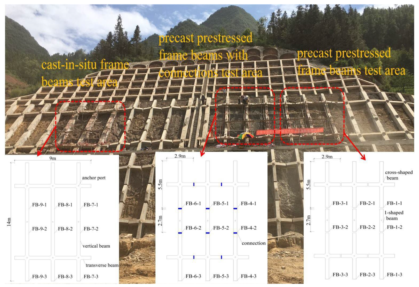
2.1. Project View
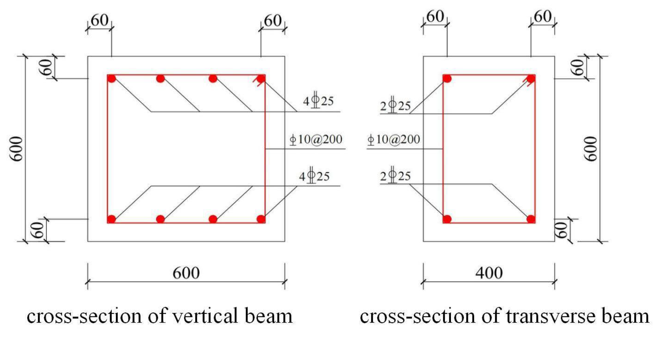
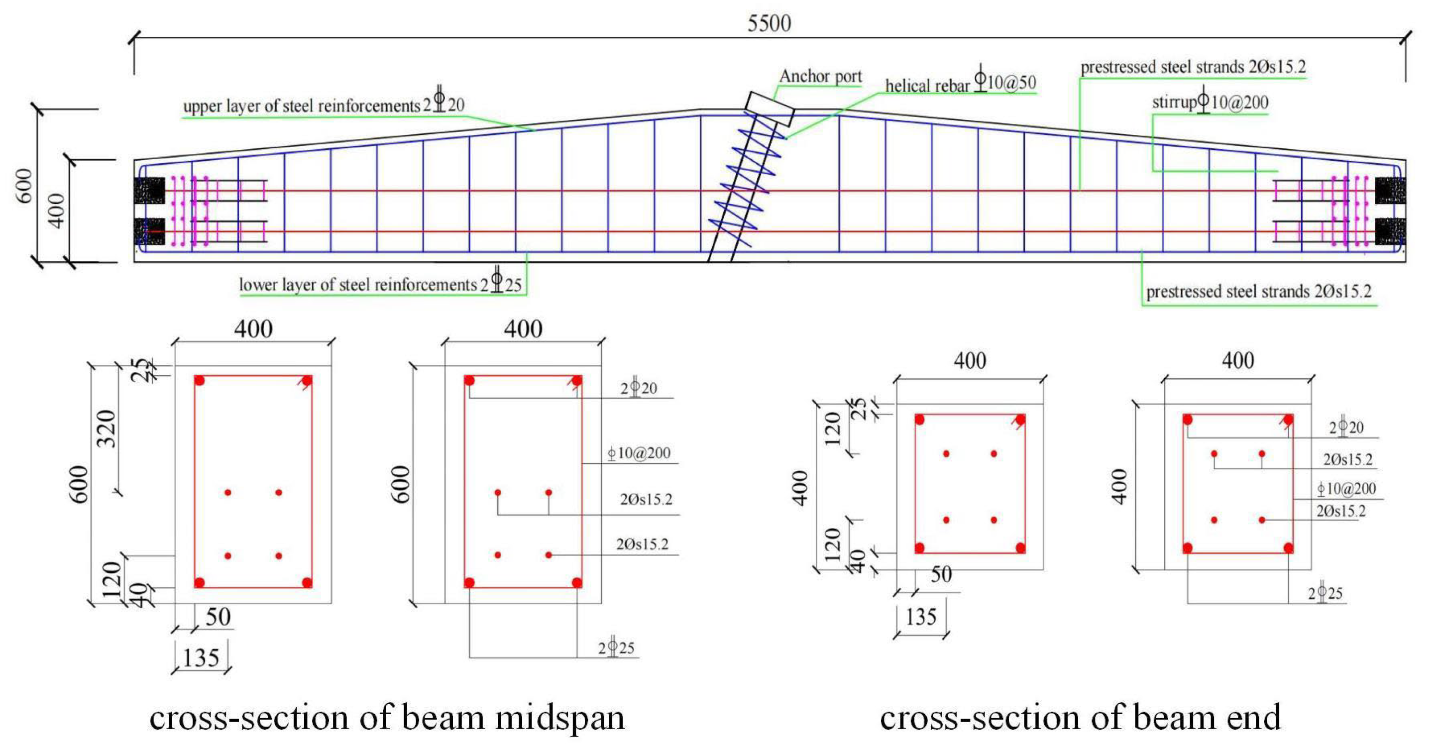
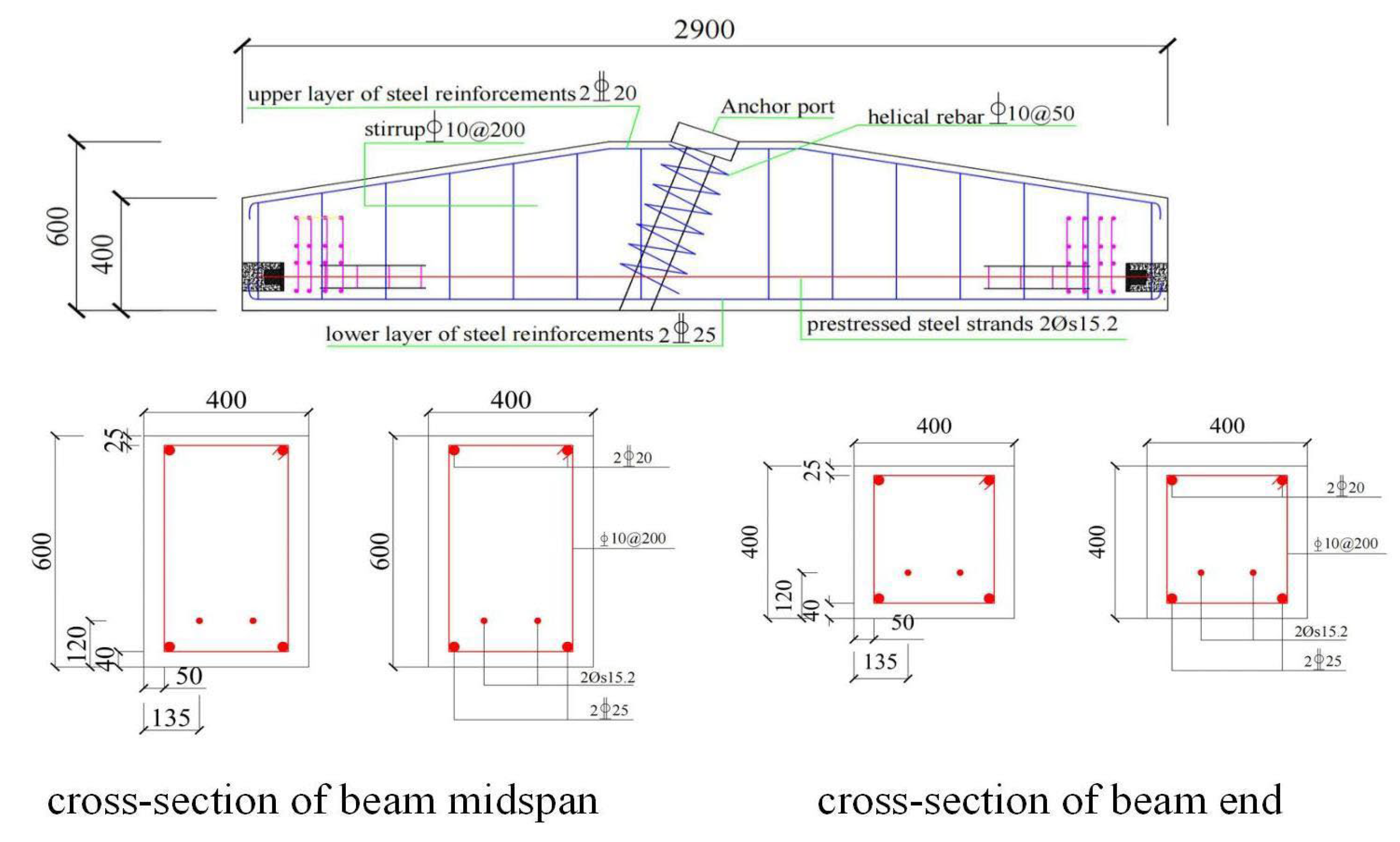
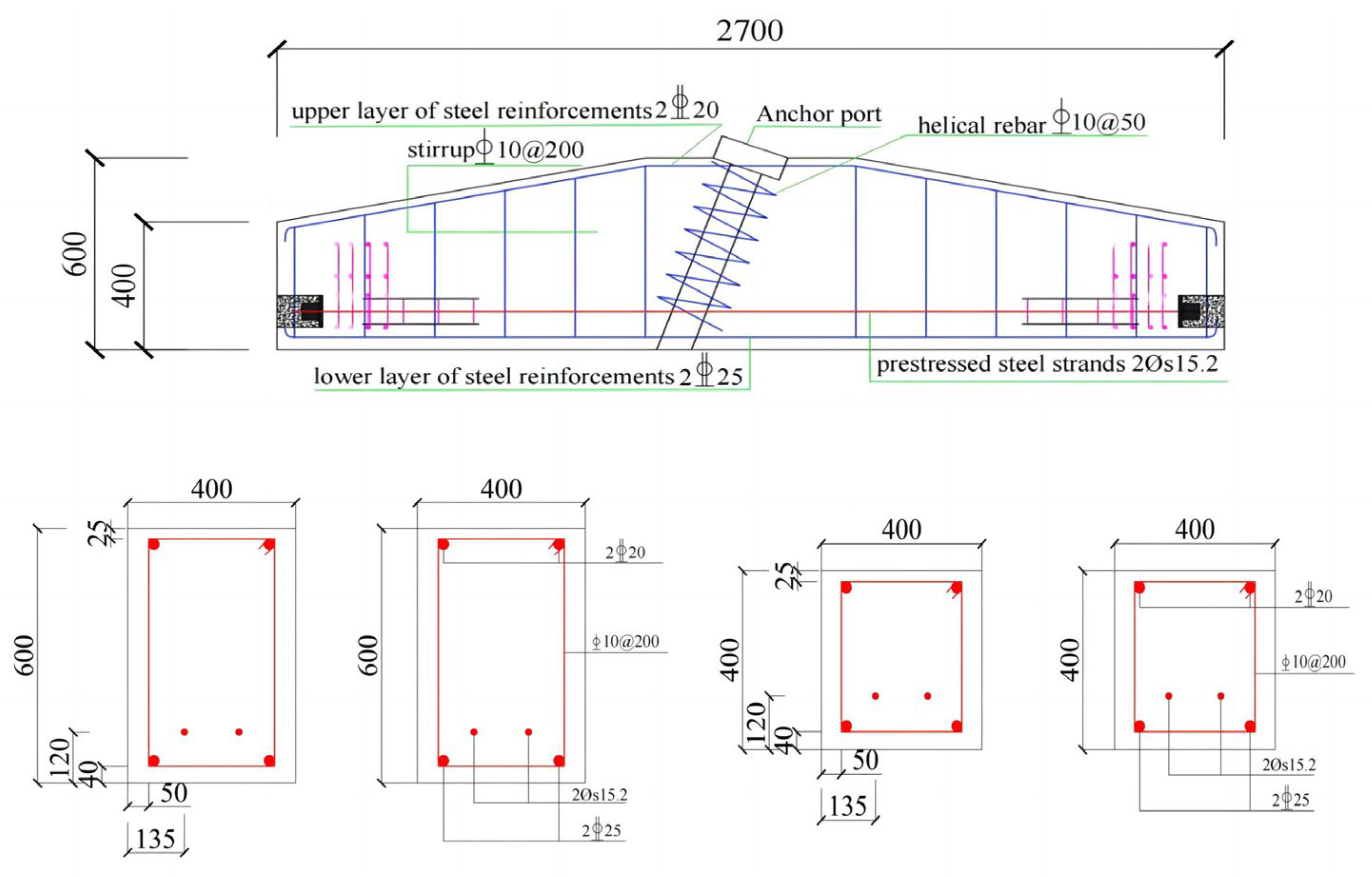
2.2. Preparation and Assembly of the Frame Beams
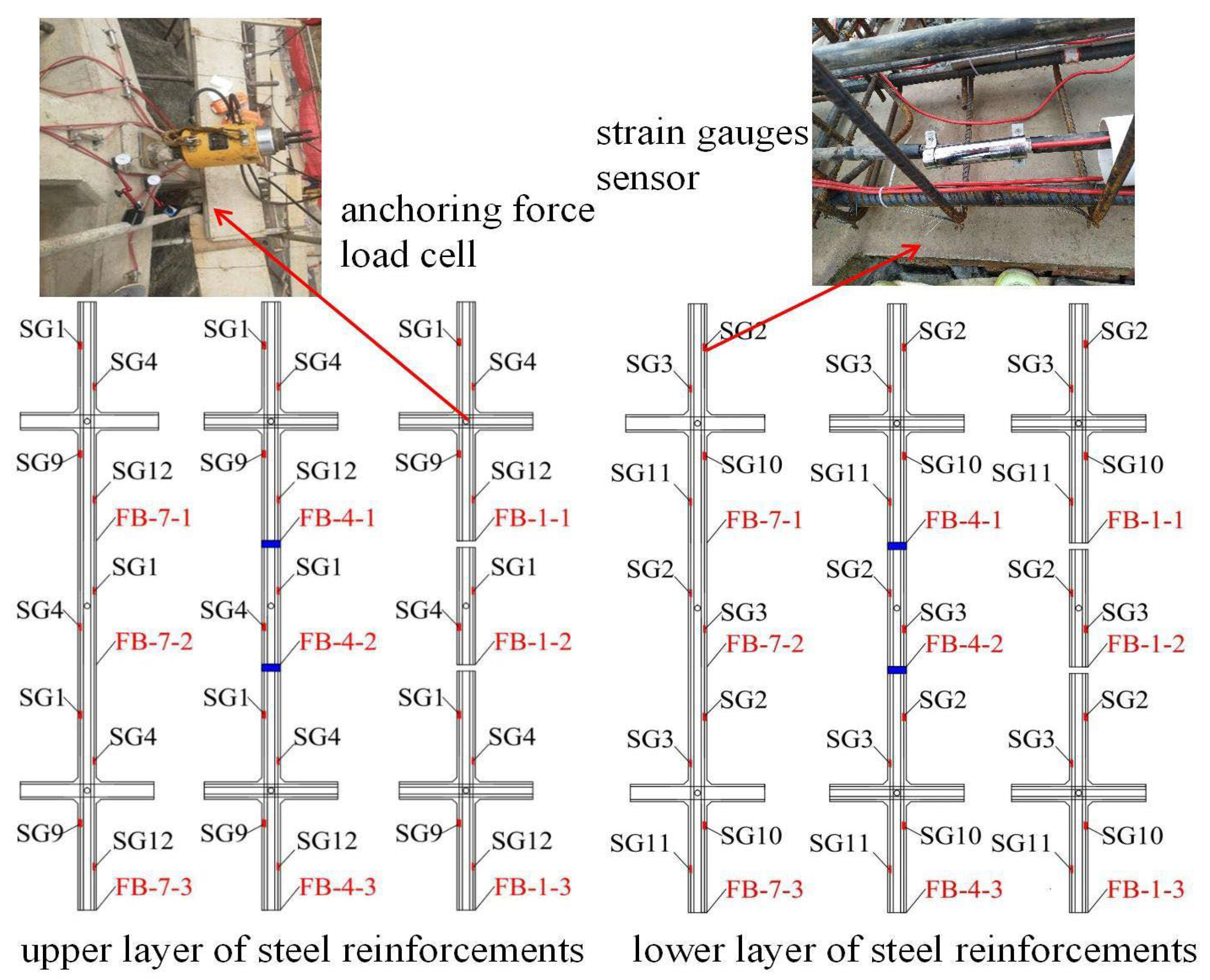
2.3. Experiment Design
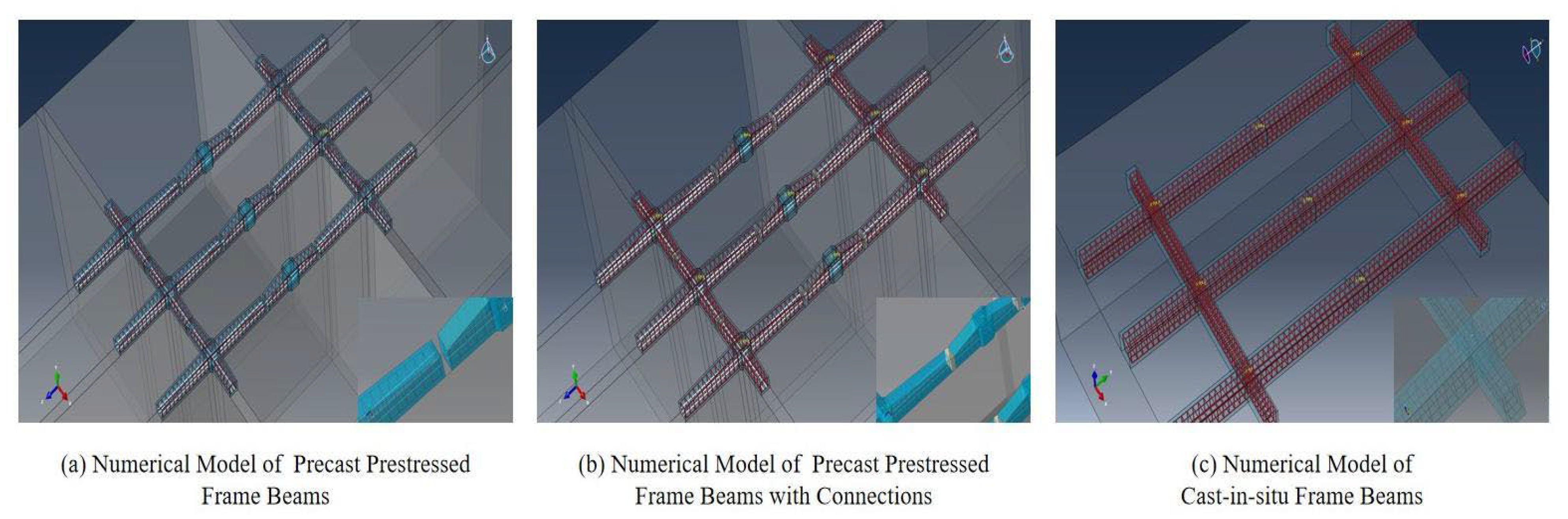
3. Numerical Study
4. Results and Discussions
4.1. The Analysis of Steel Reinforcement Forces
- (1)
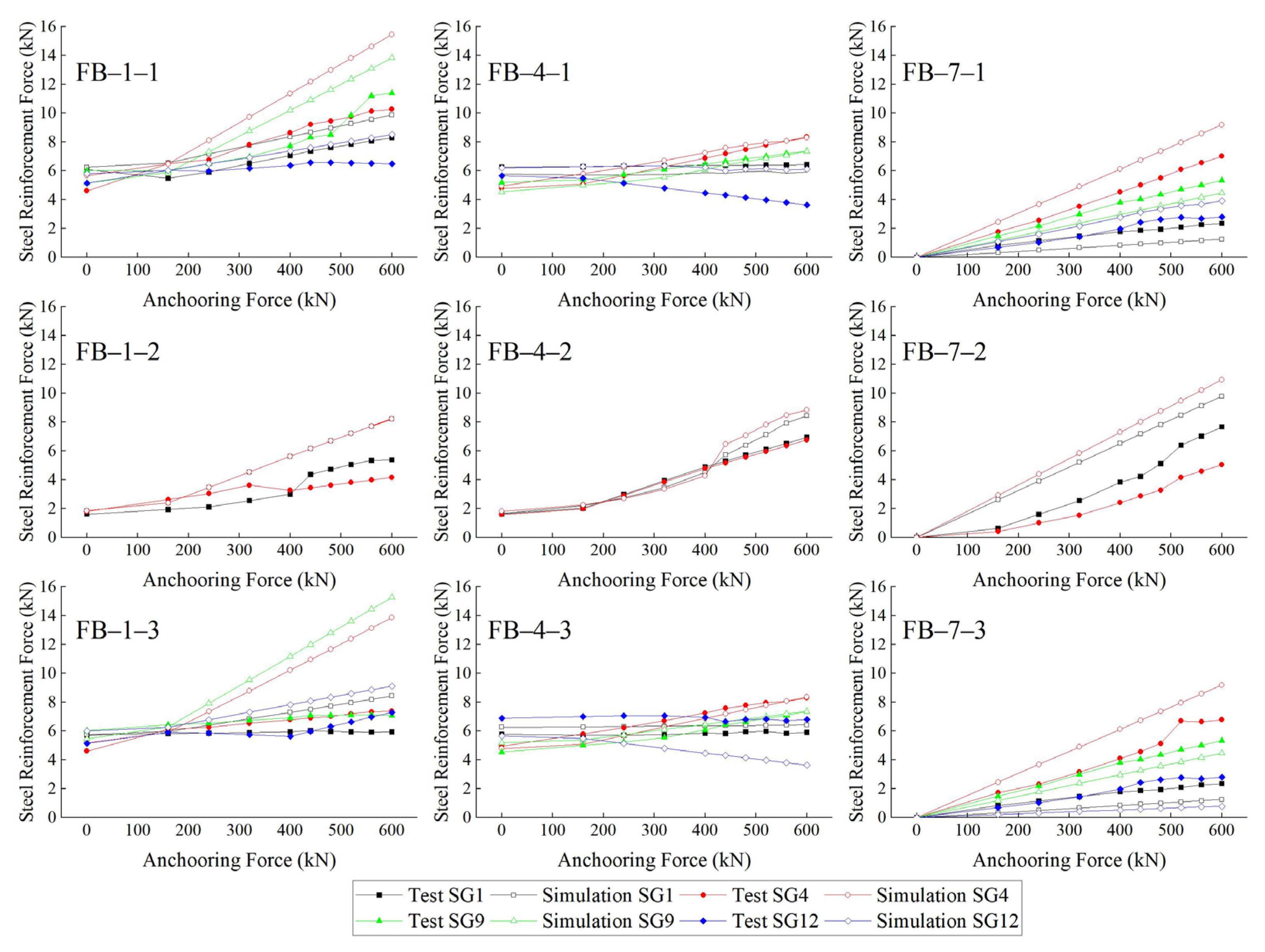
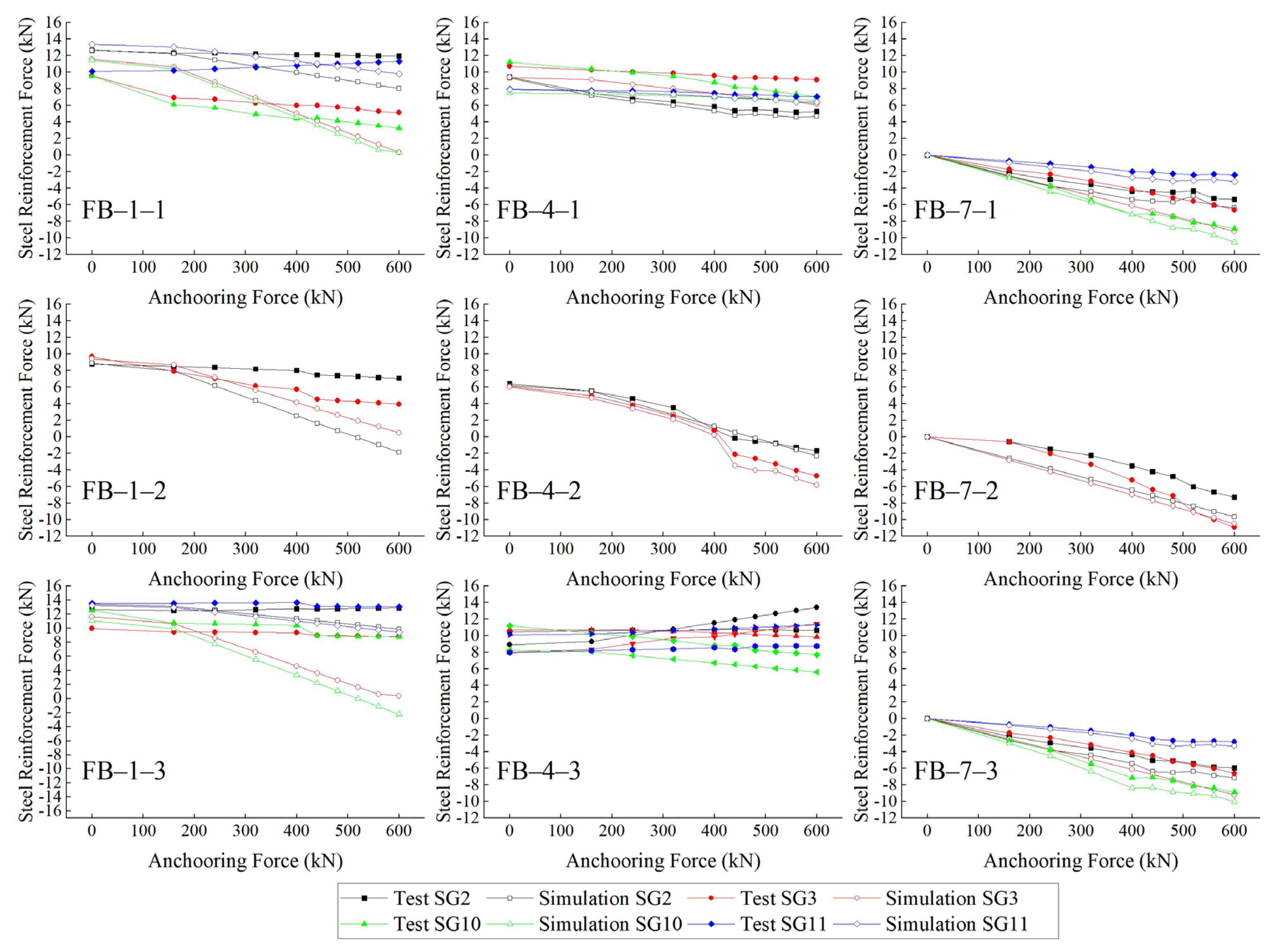
- As the anchoring force increased, the forces in the upper layer of the longitudinal steel reinforcements in all three types of frame beams increased linearly. Additionally, the forces in the lower layer of the longitudinal steel reinforcements decreased linearly. This observation implies that the three types of frame beams remained within the elastic deformation range under a 600 kN anchoring force, meeting the design load capacity requirements. It is worth noting that the volume of precast prestressed frame beams was only 57% of that of the cast-in-situ frame beams. Under the anchoring force, the upper layer steel reinforcements experienced pressure, while the lower layer steel reinforcements underwent tension.
- (2)
- In the absence of an anchoring force, the longitudinal steel reinforcement in the precast frame beams experienced pressure due to the presence of prestresses. The forces in the longitudinal steel reinforcements for the precast prestressed frame beams with connections were slightly lower than those of the precast prestressed frame beams. This phenomenon could be attributed to the precast prestressed frame beams with connections acting as a unified whole, which facilitated pressure transmission.
- (3)
- The discrepancy between the measured steel reinforcement forces and the numerical simulation values could be attributed to the fact that the numerical simulation did not account for prestress loss in the anchor cables during the calculation. To improve the accuracy of the numerical simulation, it would be appropriate to apply a suitable reduction factor to the anchoring force when studying the steel reinforcement forces of the frame beams with an anchoring force.
- (4)
- The steel reinforcement forces obtained from the field test and numerical simulations closely matched, mutually validating the accuracy of the data.
4.2. The Analysis of Section Bending Moments
- (1)
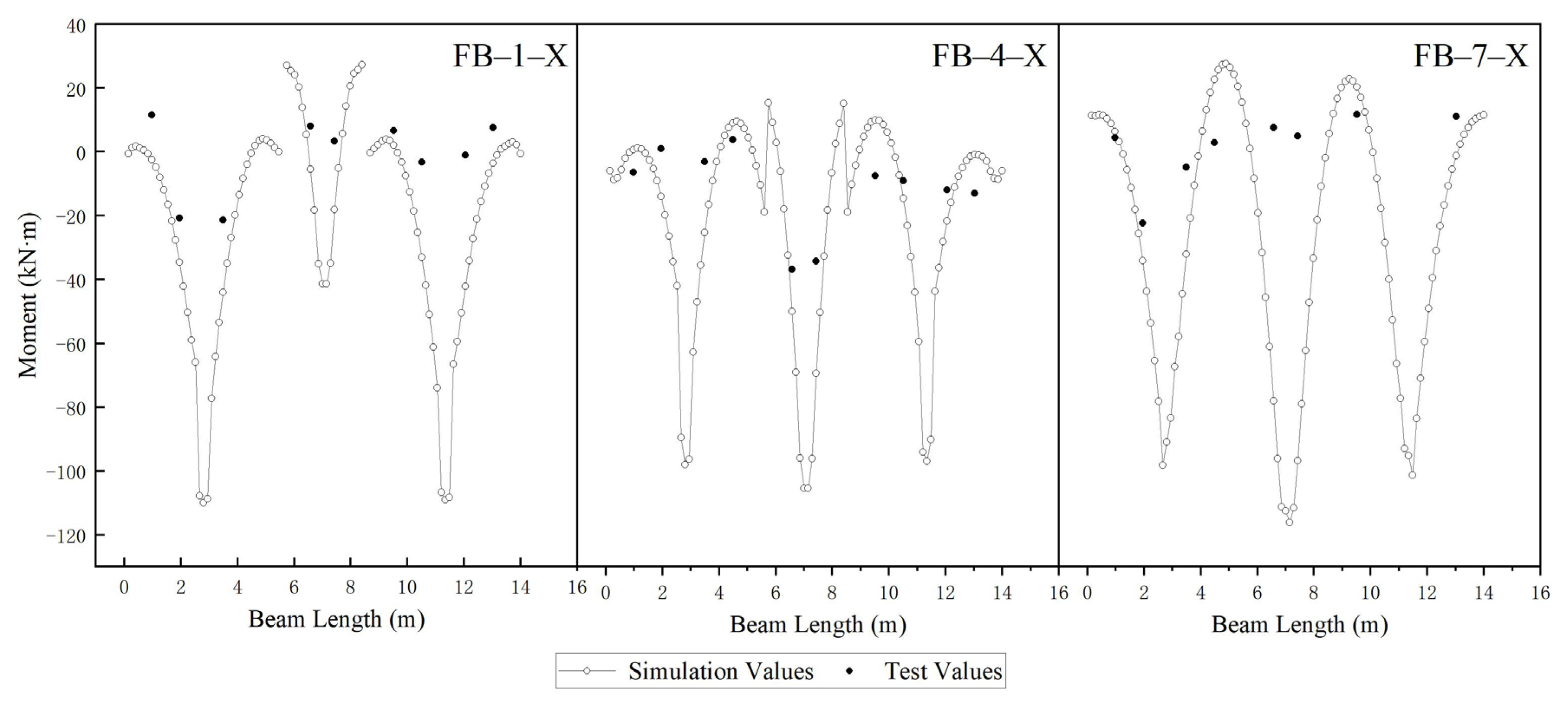
- In Figure 10, the bending moments obtained from the field test and numerical simulations were in substantial agreement, validating the accuracy of the data. Notably, most measured section bending moments were generally higher than the numerical values. This discrepancy could be attributed to the numerical simulations not accounting for the loss of prestresses in the anchor cables and other unavoidable interfering factors in the field test, such as uneven soil distribution, frame beam disturbance, temperature, etc.
- (2)
- Figure 10 indicates that the bending moment range for precast prestressed frame beams was −110 to −30 kN·m; for precast prestressed frame beams with connections, the range was from −70 to −20 kN·m; and for cast-in-situ frame beams, it fell within the range of −140 to −20 kN·m. This suggests that precast prestressed frame beams exhibited better load-bearing performance. This improvement could be attributed to the presence of prestresses in the precast frame beams, which could offset some bending moments generated by the anchoring force. Additionally, connecting all precast prestressed frames optimized their load-bearing performance.
- (3)
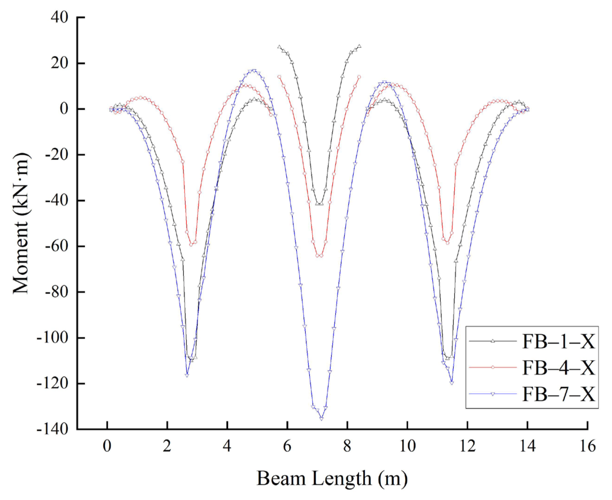
- In Figure 11, it is evident that the maximum bending moment for all three types of frame beams occurred at the anchor point. Notably, the maximum bending moment for precast prestressed frame beams with connections was 60 kN·m smaller than that for cast-in-situ frame beams. This reduction was attributed to the bending moment generated by prestresses in the precast prestressed frame beams, countering a portion of the bending moment caused by the anchoring force.
- (4)
- The maximum bending moment in the precast prestressed frame beams with connections was significantly lower than that in the precast prestressed frame beams. This phenomenon could be attributed to the precast prestressed frame beams with connections functioning as an integrated entity, facilitating the distribution and sharing of bending moments among the components. Consequently, the bending moment distribution in the precast prestressed frame beams with connections was more uniform.
5. Conclusions
- (1)
- The field test results closely aligned with the numerical values, affirming the reliability of the simulation approach employed in this study. This method can be extended to exploring diverse properties and characteristics of frame beams with anchor cables, thereby paving the way for further research in this field.
- (2)
- Throughout the anchoring force loading process, all three types of frame beams remained within the elastic range; it was shown that three types of frame beams met the design requirements. However, it is crucial to emphasize that the volume of the precast frame beams was merely 57% of that of the cast-in-situ frame beams. Furthermore, the precast prestressed frame beams exhibited superior load-bearing performance. This improvement was primarily attributed to prestresses in the precast prestressed frame beams.
- (3)
- When the anchoring force reached 600 kN, the maximum bending moment in the precast prestressed frame beams with connections was 60 kN·m less than that in the cast-in-situ frame beams. The reduction could be attributed to the bending moment generated by the prestresses in the precast prestressed frame beams, which counteracted a portion of the bending moment caused by the anchoring force.
- (4)
- The precast prestressed frame beams with connections outperformed precast frame beams in terms of steel reinforcement forces and section bending moments. This improvement could be attributed to the precast prestressed frame beams with connections functioning as an integrated entity, allowing for the transfer of forces and bending moments at the connection points, resulting in a more even distribution of forces and moments.
- (5)
- The numerical results of section bending moments were generally lower than the field test values. When using numerical simulation methods to study the bending moments of anchor frame beams, applying a suitable amplification factor to the numerical values may be appropriate.
Author Contributions
Funding
Data Availability Statement
Conflicts of Interest
References
- Choi, K.Y.; Cheung, R.W.M. Landslide disaster prevention and mitigation through works in Hong Kong. J. Rock Mech. Geotech. Eng. 2013, 5, 354–365. [Google Scholar] [CrossRef]
- Yang, G.; Zhong, Z.; Zhang, Y.; Fu, X. Optimal design of anchor cables for slope reinforcement based on stress and displacement fields. J. Rock Mech. Geotech. Eng. 2015, 7, 411–420. [Google Scholar] [CrossRef]
- Lin, Y.Y.; Li, Y.; Guolin, Y.; Li, Y. Experimental and numerical study on the seismic behavior of anchoring frame beam supporting soil slope on rock mass. Soil Dyn. Earthq. Eng. 2017, 98, 12–23. [Google Scholar] [CrossRef]
- Ge, Y.; Tang, H.; Ez Eldin, M.A.M.; Chen, H.; Zhong, P.; Zhang, L.; Fang, K. Deposit characteristics of the Jiweishan rapid long-runout landslide based on field investigation and numerical modeling. Bull. Eng. Geol. Environ. 2018, 78, 4383–4396. [Google Scholar] [CrossRef]
- Deng, D.; Zhao, L.; Li, L. Limit-Equilibrium Analysis on Stability of a Reinforced Slope with a Grid Beam Anchored by Cables. Int. J. Geomech. 2017, 17, 06017013. [Google Scholar] [CrossRef]
- Yan, M.; Xia, Y.; Liu, T.; Bowa, V.M. Limit analysis under seismic conditions of a slope reinforced with prestressed anchor cables. Comput. Geotech. 2019, 108, 226–233. [Google Scholar] [CrossRef]
- Zhou, C.; Hu, Y.; Xiao, T.; Ou, Q.; Wang, L. Analytical model for reinforcement effect and load transfer of pre-stressed anchor cable with bore deviation. Constr. Build. Mater. 2023, 379, 131219. [Google Scholar] [CrossRef]
- Ye, S.; Fang, G.; Ma, X. Reliability Analysis of Grillage Flexible Slope Supporting Structure with Anchors Considering Fuzzy Transitional Interval and Fuzzy Randomness of Soil Parameters. Arab. J. Sci. Eng. 2019, 44, 8849–8857. [Google Scholar] [CrossRef]
- Li, C.; Wu, J.; Wang, J.; Li, X. Layout and length optimization of anchor cables for reinforcing rock wedges. Bull. Eng. Geol. Environ. 2015, 75, 1399–1412. [Google Scholar] [CrossRef]
- Zhang, T.; Zheng, H.; Sun, C. Global method for stability analysis of anchored slopes. Int. J. Numer. Anal. Methods Geomech. 2018, 43, 124–137. [Google Scholar] [CrossRef]
- Shi, K.; Wu, X.; Liu, Z.; Dai, S. Coupled calculation model for anchoring force loss in a slope reinforced by a frame beam and anchor cables. Eng. Geol. 2019, 260, 105245. [Google Scholar] [CrossRef]
- Wu, L.; Huang, R. Numerical simulation and optimum design of anchor frame beam strengthening expansive soil roadcut slope. Rock Soil Mech. 2006, 27, 605–614. [Google Scholar] [CrossRef]
- Lin, Y.; Cheng, X.; Yang, G.; Li, Y. Seismic response of a sheet-pile wall with anchoring frame beam by numerical simulation and shaking table test. Soil Dyn. Earthq. Eng. 2018, 115, 352–364. [Google Scholar] [CrossRef]
- Ye, W.; Zhou, Y.; Ye, S. Analysis of Deformation and Stress Characteristics of Anchored-Frame Structures for Slope Stabilization. Adv. Civ. Eng. 2020, 2020, e8870802. [Google Scholar] [CrossRef]
- Li, J.; Zhu, Y.; Ye, S.; Ma, X. Internal Force Analysis and Field Test of Lattice Beam Based on Winkler Theory for Elastic Foundation Beam. Math. Probl. Eng. 2019, 2019, 5130654. [Google Scholar] [CrossRef]
- Yuan, P.; Liu, Y. Analysis on Slope Frame Ground Beam under Dynamic Action. IERI Procedia 2012, 1, 94–100. [Google Scholar] [CrossRef]
- Fan, J.; Shi-jiao, Y.; Deng, B.; Sun, B.; Liu, T. A Comparison of Load Distribution Methods at the Node and Internal Force Analysis of the Lattice Beam Based on the Winkler Foundation Model. Buildings 2023, 13, 1731. [Google Scholar] [CrossRef]
- Lian, J.; Wu, J.; Luo, Q. Theoretical analysis and optimization of frame protection to control shallow slope stability and soil erosion. Transp. Geotech. 2022, 33, 100724. [Google Scholar] [CrossRef]
- Cai, F.; Ugai, K. Reinforcing mechanism of anchors in slopes: A numerical comparison of results of LEM and FEM. Int. J. Numer. Anal. Methods Geomech. 2003, 27, 549–564. [Google Scholar] [CrossRef]
- Zheng, H.; Liu, D.F.; Li, C.G. Slope stability analysis based on elasto-plastic finite element method. Int. J. Numer. Methods Eng. 2005, 64, 1871–1888. [Google Scholar] [CrossRef]
- Zhu, C.; He, M.; Karakus, M.; Zhang, X.; Tao, Z. Numerical simulations of the failure process of anaclinal slope physical model and control mechanism of negative Poisson’s ratio cable. Bull. Eng. Geol. Environ. 2021, 80, 3365–3380. [Google Scholar] [CrossRef]
- Zhu, H.; Xiang, Q.; Luo, B.; Du, Y.; Li, M. Evaluation of failure risk for prestressed anchor cables based on the AHP-ideal point method: An engineering application. Eng. Fail. Anal. 2022, 138, 106293. [Google Scholar] [CrossRef]
- Steinle, A.; Bachmann, H.; Tillmann, M. Precast Concrete Structures; Wiley: Hoboken, NJ, USA, 2019. [Google Scholar]
- Japan Precast Concrete Frame Association. PC Frame Construction Design and Construction Guide; PC Frame Association: Tokyo, Japan, 2012. (In Japanese) [Google Scholar]
- Japan Precast Concrete Frame Association. PC Frame Construction Standard Calculation Data; PC Frame Association: Tokyo, Japan, 2012. (In Japanese) [Google Scholar]
- Čajka, R.; Navrátil, J. Numerical Solution of Prestressed Foundation—Subsoil Interaction Using FEM. Key Eng. Mater 2020, 832, 81–88. [Google Scholar] [CrossRef]
- Ye, Y.; Wei, S.; Cai, D.; Yang, J.; Wei, P.; Yue, C.; Wu, S. Calculation method for internal force and deformation of the prestressed I-beam on the elastic foundation. Front. Earth Sci. 2023, 10, 996876. [Google Scholar] [CrossRef]

| Parameter | Type | Strength (MPa) | Density (kg/m3) | Young’s Modulus (Pa) | Poisson’s Ratio | Dilatation Coefficient (1/°C) |
|---|---|---|---|---|---|---|
| Steel reinforcement |  | 400 | 7800 | 2 × 10¹¹ | 0.25 | — |
| Prestressed steel strand | φ15.24 | 1860 | 7800 | 2 × 10¹¹ | 0.25 | 1.2×10⁻⁵ |
| Concrete | C40 | 40 | 2643 | 3 × 10¹⁰ | 0.2 | — |
| Soil | — | — | 2000 | 3 × 10⁷ | 0.3 | — |
Disclaimer/Publisher’s Note: The statements, opinions and data contained in all publications are solely those of the individual author(s) and contributor(s) and not of MDPI and/or the editor(s). MDPI and/or the editor(s) disclaim responsibility for any injury to people or property resulting from any ideas, methods, instructions or products referred to in the content. |
© 2024 by the authors. Licensee MDPI, Basel, Switzerland. This article is an open access article distributed under the terms and conditions of the Creative Commons Attribution (CC BY) license (https://creativecommons.org/licenses/by/4.0/).
Share and Cite
Qin, M.; Dou, G.; Yang, J.; Wei, S. Field Test and Numerical Study of Three Types of Frame Beams Subjected to a 600 kN Anchoring Force. Buildings 2024, 14, 401. https://doi.org/10.3390/buildings14020401
Qin M, Dou G, Yang J, Wei S. Field Test and Numerical Study of Three Types of Frame Beams Subjected to a 600 kN Anchoring Force. Buildings. 2024; 14(2):401. https://doi.org/10.3390/buildings14020401
Chicago/Turabian StyleQin, Mengchun, Guosong Dou, Jianmin Yang, and Shaowei Wei. 2024. "Field Test and Numerical Study of Three Types of Frame Beams Subjected to a 600 kN Anchoring Force" Buildings 14, no. 2: 401. https://doi.org/10.3390/buildings14020401
APA StyleQin, M., Dou, G., Yang, J., & Wei, S. (2024). Field Test and Numerical Study of Three Types of Frame Beams Subjected to a 600 kN Anchoring Force. Buildings, 14(2), 401. https://doi.org/10.3390/buildings14020401