Article

Experimental Study on the Effects of Straight and Ring-Type Steel Fibres on the Bond Behaviour of Steel Bars in Rubber-Recycled Aggregate Concrete

1
School of Civil and Transportation Engineering, Guangdong University of Technology, Guangzhou 510006, China
2
China Railway 17th Bureau Group Co., Ltd., Taiyuan 030006, China
3
Guangdong Construction Polytechnic, Guangzhou 510440, China
4
China Railway 17th Bureau Group (Guangzhou) Construction Co., Ltd., Guangzhou 510700, China
*
Author to whom correspondence should be addressed.
Buildings 2024, 14(2), 504; https://doi.org/10.3390/buildings14020504
Submission received: 7 January 2024 / Revised: 24 January 2024 / Accepted: 7 February 2024 / Published: 12 February 2024
(This article belongs to the Special Issue New Concrete Materials: Performance Analysis and Research)

Abstract

:
The application range of rubber-recycled aggregate concrete (RRAC), a new type of green building material, is currently limited due to performance defects, including low hardness, high water absorption, and poor adhesion. To expand its application in reinforced concrete structures, it is crucial to enhance the bonding performance between RRAC and steel bars. In this study, the effects of adding straight steel fibres (SSFs) and ring-type steel fibres (RSFs) to RRAC were investigated, in order to enhance the bonding performance. To investigate the impact of steel fibres (SFs) on the bonding properties of RRAC and steel bars, a total of 51 specimens were subjected to pull-out tests to systematically examine the impact of SSF and RSF dosages on the bonding performance. The results demonstrated that incorporating the optimal amount of SSFs and RSFs can significantly improve the bond strength and bond stiffness. Moreover, the combined use of SSFs and RSFs yielded even better enhancement effects. The RRAC exhibited remarkable performance, when the total content of SFs was 1.2% and the proportion of RSFs 75%. In this case, the bond strength and bond stiffness were enhanced by 3.7% and 53.88%, respectively. Finally, a bond–slip constitutive model for RRAC and steel bar was established. The combined use of SSFs and RSFs minimizes the limitations of poor mechanical properties in traditional RRAC and holds significant value for the widespread adoption and application of RRAC.

1. Introduction

Improper management of waste rubber tires and construction waste globally has led to escalating environmental problems [1,2,3,4,5,6]. The construction industry is currently experiencing a shortage of natural resources, which highlights the importance of recycling waste materials for the sustainable development of the industry [7,8,9,10,11]. A potential remedy involves utilizing this waste through the substitution of rubber powders (RPs) for fine aggregate and recycled coarse aggregate (RCA) for coarse aggregate in concrete. This innovative approach results in the production of rubber-recycled aggregate concrete (RRAC). Numerous studies have been conducted on the performance and application of RRAC by researchers. The addition of suitable quantities of RPs and RCA to ordinary concrete can enhance its durability, impact resistance, and noise reduction capabilities to a certain extent [12,13,14,15]. However, excessive amounts of RPs and RCA may lead to significant strength decrease in concrete [16,17]. Gholampout et al. [18] conducted an experiment where they added varying amounts of RPs to concrete. Their findings revealed that as the content of RPs increased, the compressive strength of the concrete decreased. Chen et al. [19] discovered that when RCA was used exclusively, the mechanical strength of recycled aggregate concrete (RAC) was only 77% of that of natural aggregate concrete. Furthermore, Zrar et al. [20] demonstrated that both the compressive strength and tensile strength of concrete decreased significantly with an increase in the substitution rate of RPs and RCA. The mechanical properties of RRAC are flawed, and with the growing use of waste materials in the construction industry, it is becoming challenging to promote and apply RRAC if its overall performance cannot be enhanced. This limitation restricts its potential applications. Currently, RRAC is mainly used for non-load-bearing components that have low mechanical strength requirements, such as roads and airport runways [21,22]. To broaden the application range of RRAC and increase the utilization of waste rubber tires and construction waste, it is crucial to find methods to enhance its mechanical properties.
The incorporation of SFs in concrete has proven to be an effective method for enhancing its mechanical properties. SFs act as a bridge within the concrete structure, effectively preventing the formation of micro-cracks and reducing the occurrence of macro-cracks. This results in a significant improvement in the concrete’s splitting tensile strength, shear strength, and bending resistance [23,24,25]. Moreover, when adding a certain amount of SFs to concrete, the compressive failure mode shifted from brittleness to ductility, and its compressive performance was also improved [26]. Consequently, scholars have conducted extensive research on the use of SFs to enhance the properties of RRAC. Shahjalal et al. [17] demonstrated that the incorporation of SFs enhances the compressive strength, tensile strength, and ductility of RRAC. In a separate study, Xie et al. [27] investigated the impact of SFs on the fracture properties of RRAC. The findings indicate that the inclusion of SFs enhances the resistance to fracture toughness instability in RRAC. Although SFs have been proved to enhance the mechanical properties of RRAC, there are several shortcomings in the current research in this field. These can be summarized as outlined below. (1) The number of closed regions and the area of the ring formed by SFs in concrete have a notable impact on the mechanical properties of concrete [28]. However, the existing research has primarily focused on SF-enhanced RRAC with single closed regions, and there is a dearth of studies on the formation of SFs with multiple closed regions and larger ring areas. (2) The post-peak performance of straight steel fibre reinforced concrete (SSFRC) is determined by the ultimate tensile strength of SSFs passing through the failure surface [29]. However, the anchoring performance of SSFs and concrete is insufficient, resulting in SSFs being pulled out without yielding when the SSFRC is destroyed. As a result, the performance of SSFs has not been fully utilized. (3) SSFs only have an inhibitory effect on the cracks they pass through and have little impact on the cracks in their vicinity. Therefore, the enhancement effect of SSFs on concrete is limited. When subjected to external loads, ensuring the restraint effect on the concrete matrix solely through the use of SSFs can be challenging. This is particularly true for concrete with relatively weak mechanical properties, like RRAC.
In order to address these issues, this study proposes the use of RSFs to enhance RRAC. RSFs offer several advantages over SSFs as follow. (1) RSFs form a circular occlusal surface in concrete, which significantly improves the anchoring effect of RSFs and concrete. The mechanism of RSF reinforced concrete is similar to that inducing RSFs to break after yielding, allowing RSFs to fully demonstrate their performance [30]. (2) RSF provides a wider protection range compared to SSFs. When RSFs are incorporated into concrete, a closed system is formed. This closed system helps restrain and protect the concrete matrix when it is damaged by external forces, inhibiting the development of concrete cracks within the closed system. Choi et al. [30] demonstrated that the flexural toughness of ring-type steel fibre reinforced concrete (RSFRC) was significantly improved compared to traditional SSFRC, thus confirming the potential of RSFs in enhancing concrete performance. He et al. [31] found that incorporating an appropriate proportion of SSFs mixed with RSFs can greatly enhance the compressive performance of RRAC. This finding suggests that the combination of SSFs and RSFs could be a reliable approach to promoting RRAC.
At present, reinforced concrete structure remains the most commonly employed structural form in building structures [32,33,34,35]. The fundamental mechanical properties of concrete and the bonding properties between the steel bars and concrete are crucial factors that determine the suitability of concrete material for widespread use in reinforced concrete structures [36]. However, current research only focuses on the impact of SSFs and RSFs on the fundamental mechanical properties of RRAC. To further enhance the applicability of RRAC, it is crucial to investigate and understand the effects of SSFs and RSFs on the bonding properties between RRAC and steel bars. In this study, RRAC was used as a matrix to investigate the impact of SSFs and RSFs dosages on the bonding performance of RRAC and steel bars; the optimal content of SSFs and RSFs were also determined. Additionally, a bond–slip constitutive model for RRAC and steel bars was developed. The findings of this study are highly significant as they contribute to the promotion of RRAC, which has the potential to address environmental pollution caused by waste rubber tires and construction waste. Furthermore, it can facilitate the green transformation of the construction industry.

2. Experimental Programme

2.1. Materials Properties

The raw materials used in this study include cement, water, river sand, RCA, RPs, SSFs, and RSFs. Ordinary Portland cement (P.O 42.5) was used with an apparent density of 3112 kg/m3. The test water used in this experiment was ordinary tap water with a density of 995 kg/m3. For the fine aggregate of concrete, river sand with a maximum particle size of 5 mm was utilized. The density, fineness modulus, water content, and water absorption of this sand were 2642 kg/m3, 2.17, 0.12%, and 0.18%, respectively. Additionally, the particle size of RCA ranged from 5 mm to 25 mm, and its apparent density, water absorption, and moisture content were 2536.9 kg/m3, 2.45%, 2.10%, respectively. To prevent impurities on the surface of the aggregate from affecting the bonding performance of the interface, the aggregate was subjected to screening, cleaning, and drying after which it was ready for use. The gradation of the aggregate after mechanical screening can be seen in Figure 1. RPs, which are made from waste rubber tires, undergo a process of washing, drying, and mechanical crushing. The RPs have a particle size of 0.85 mm and an apparent density of 988 kg/m3. The SSFs and RSFs used in this study are illustrated in Figure 2. The ends of the SSFs were processed into end hooks to improve the anchoring effect between the SSFs and concrete. The material properties of the SSFs and RSFs are presented in Table 1. The pull-out specimens were constructed using HRB400 hot-rolled ribbed bars, which had a length of 420 mm and a diameter of 10 mm. The steel bar had a yield strength of 440 MPa, a tensile strength of 550 MPa, and an elastic modulus of 200 GPa.

2.2. Mix Proportions

A total of 17 groups of mix proportions and their compressive strength were designed for this study, as presented in Table 2 (more relative parameters of mechanical properties can be found in our previous research [31]). Three specimens were created for each group, resulting in a total of 51 pull-out specimens. The main parameters focused on the overall amount of SFs and the ratio of RSFs in relation to the total amount of SFs. The total amount of SFs refers to the percentage of SF volume in the volume of concrete. Excessive use of steel fibres can result in fibre agglomeration and a decrease in the workability and mechanical properties of concrete. To address these problems, four different levels of SF content were selected: 0%, 0.4%, 0.8%, and 1.2%. The ratio of RSFs to the total volume of SFs is calculated by dividing the volume of RSFs by the total volume of SFs, and it is also expressed as a percentage. Five different ratios were set: 0%, 25%, 50%, 75%, and 100%. Based on our pre-experiment and taking into account the environmental advantages of utilizing waste rubber [31], we incorporated RPs by substituting a portion of the fine aggregate with an equal volume, while the incorporation ratio was consistently set at 20%. Additionally, the water–cement ratio was fixed at 0.38 (as the aggregate was dried after drying, the moisture content of the aggregate was not taken into consideration). Moreover, the objective of this study was to investigate the effect of SSFs and RSFs on the bonding properties of RRAC and steel bars. Therefore, only the reference specimen “R0S0RS0” was designed, and ordinary concrete was not considered.

2.3. Design and Preparation of Pull-Out Specimens

All the specimens for the pull-out test in this study were made of concrete cubes with a length of 150 mm and steel bars with a length of 420 mm. The steel mould and the process for making pull-out specimens are shown in Figure 3. The steel mould consists of an upper steel mould and a lower steel mould connected by bolts. The upper steel mould is made up of two L-shaped steel mould plates connected by bolts. The lower steel mould is a steel plate with a middle opening and a steel casing with a diameter of 20 mm and a length of 50 mm. To prevent stress state difference between the end of the concrete and the steel bar during the loading process, an unbonded area with a length of 50 mm was set at the bottom of the concrete, specifically at the top area of the steel casing. This was achieved by embedding a plastic pipe cap at both the upper and lower parts of the steel casing. A hole was then opened in the middle of the plastic pipe cap, allowing the steel bar to pass through. To prevent the cement slurry from seeping during pouring, the gap between the plastic pipe cap and the steel casing was sealed with lime mud. The steel bar was then inserted into the bottom of the steel mould through the lower plastic pipe cap, the steel sleeve, and finally the upper plastic pipe cap. The exposed part of the upper plastic pipe cap serves as the bonding area for the steel bar. The length of this bonding area was set to 5-times the diameter of the steel bar (5d0) to maximize the bonding performance between the steel bar and concrete [37]. After the steel bar passes through, the three bolts at the lower part of the steel sleeve should be tightened to secure the steel bar in the centre of the steel sleeve. Following that, the upper and lower steel moulds were assembled and placed on the platform with the opening of the steel mould facing upwards. The RRAC was then poured into the steel mould through the upper opening, and the concrete surface was vibrated using a plug-in vibrator to remove any large bubbles. After pouring for 24 h, the mould was demoulded and cured for 28 days at a temperature of 20 ± 3 °C and a relative humidity of >95%. Finally, a pull-out test was conducted.

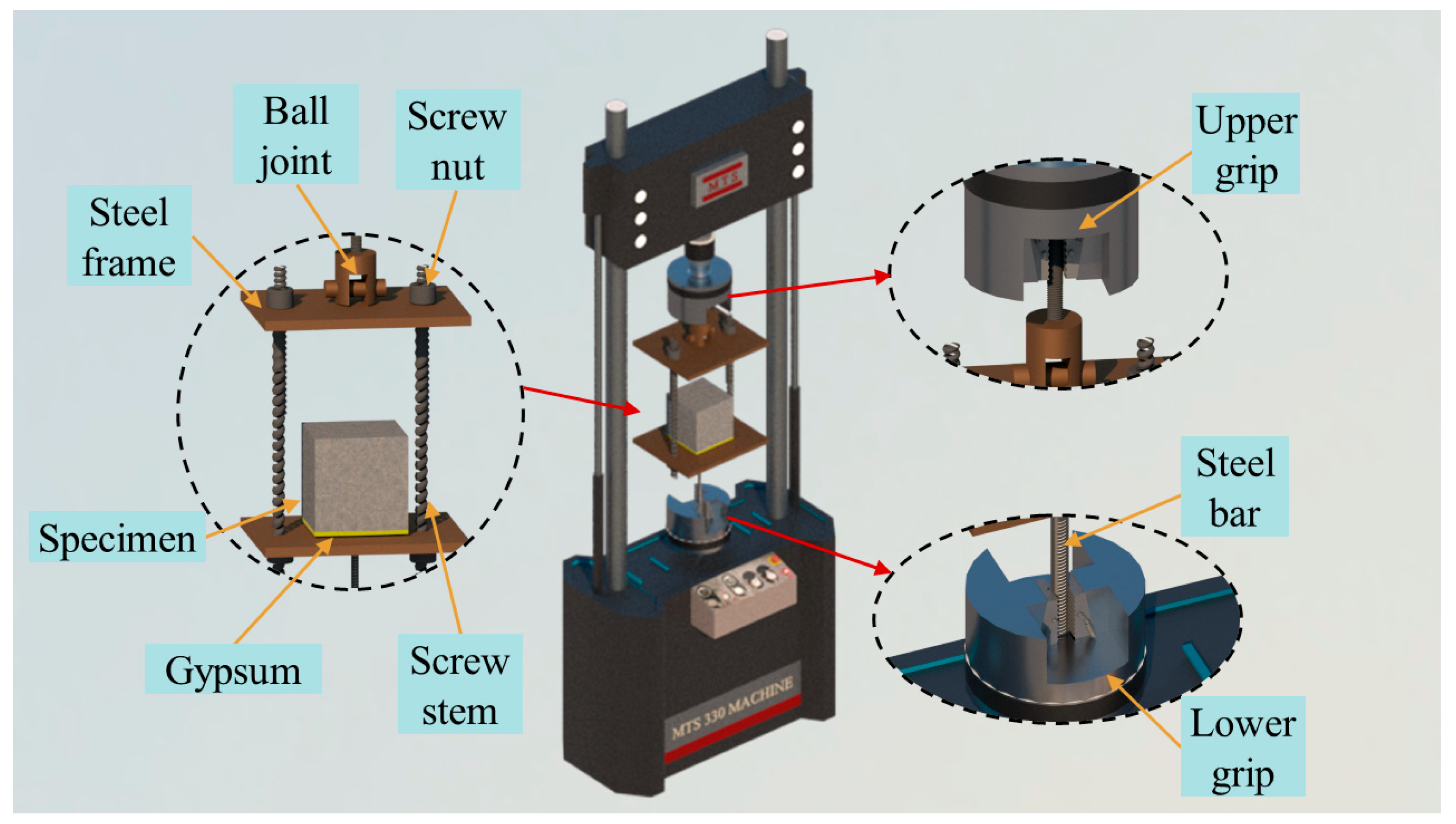
2.4. Test Setup and Machine

The tensile testing machine (MTS-370, USA) was utilized to conduct the pull-out test in this study, and the test device and machine are shown in Figure 4. The test device is connected using two steel frames and two screws in the centre. The lower clamp of the test machine clamps the steel bar of the pull-out specimen after it passes through the hole in the middle of the lower steel frame. To ensure that the test results were not affected by the uneven contact surface between the concrete and the steel plate, the bottom surface of the pull-out specimen was coated with gypsum and then placed on the steel frame. The upper steel frame has a ball hinge in the middle, and the upper pull rod of the ball hinge is clamped by the upper chuck of the testing machine. The purpose of the ball hinge is to maintain a vertical alignment between the upper and lower steel frames, preventing any eccentric tension on the steel bar. The displacement loading process was conducted at a rate of 1.2 mm/min, with the loading end positioned at the lower chuck. The tensile testing machine and the dynamic and static data acquisition instrument (JMTS-3841, China) were used to collect the pull-out force and displacement of the loading end simultaneously, at a sampling frequency of 2 Hz. The loading was halted either when the specimen was damaged or when the displacement of the loading end exceeded 25 mm (This threshold value is 2-times the rib spacing of the steel bars). It is to be noted that the slippage between the steel bar and concrete was calculated by subtracting the elongation of the steel bar from the displacement of the loading end of the steel bar. The displacement of the loading end was directly measured using a testing machine. The elongation of the steel bar was calculated based on Hooke’s law and then derived, as shown in Formula (1):
ε = Δ L L = σ E f = F A f E f
where the ε represents the strain of the steel bar, L denotes the length from the loading end of the steel bar to the midpoint of the bonding area, σ represents the stress of the steel bar, F represents the drawing force of the steel bar at the loading end, and Af represents the cross-sectional area of the steel bar.

3. Results and Discussion

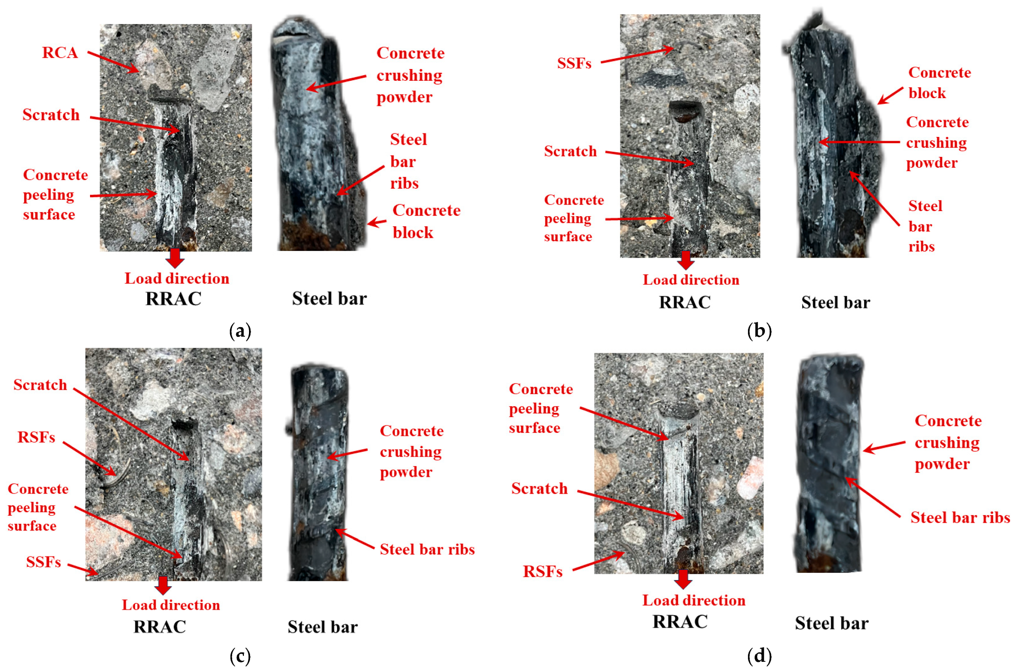
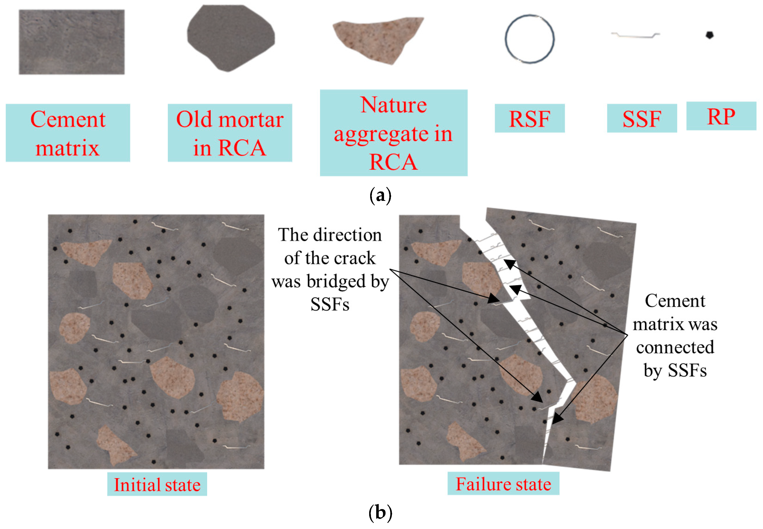
3.1. Bond Interface Damage and Bond Mechanism

The failure mode observed in all specimens was steel bar pull-out failure. As the load increased, the slip of the steel bar gradually increased, eventually leading to the test being stopped due to excessive slip causing the pull-off of the steel bar. Throughout the entire test process, there was no occurrence of concrete splitting or steel bar breaking, and the surface integrity of the specimen remained intact. The only damage observed was at the bonding interface between the steel bar and concrete. This failure mode can be attributed to the larger thickness of the concrete protective layer on the pull-out specimen, which enhances the resistance to the splitting of the surrounding concrete.
Following the completion of the pull-out test, the concrete cubes of all specimens were divided into two pieces along the longitudinal plane of the central axis of the steel bar. This allowed for observation of the bonding damage at the interface between the steel bar and the concrete. Figure 5 illustrates the damage of the bonding interface between RRAC and the steel bars with various types of SFs. Notably, the damage to the bonding interface is consistent among all specimens. The surface of the concrete bonding interface appears rough, with noticeable peeling and scratched areas, as well as residual concrete powder. In the steel bar bonding area, the ribs of the steel bar remain intact, without any instances of rib breakage. The steel ribs are filled with concrete fragments, and some concrete fragments are adhered to the steel bars. Combined with the failure mode and the damage of the bonding interface, the bonding failure of the specimen is primarily attributed to the shear failure of the concrete in the bonding area caused by the extrusion between the steel ribs. Initially, the stress triggers the activation of the bonding mechanism between the steel bar and the concrete. During this stage, the primary bonding force at the bonding interface is the chemical bonding force generated by the cement gel on the surface of the steel bar within the concrete. As the steel bars deform and start to slip, the chemical bonding force is rapidly lost. At this stage, the bonding force is sustained by the friction between the steel bar and the concrete, as well as the mechanical bite force. As the load continues to increase, the concrete in front of the steel rib is crushed due to local extrusion. This results in the radial component of the extrusion force from the steel rib on the surrounding concrete, which generates circumferential tensile stress in the concrete. When the annular tensile stress exceeds the ultimate tensile strength of concrete, it results in the formation of radial–longitudinal cracks in the concrete. However, due to the presence of a thick protective layer of concrete and the crack resistance provided by SFs, these cracks only occur in a limited area around the bonding region and do not propagate rapidly to the surface of the concrete, thereby preventing concrete splitting. As the slip of the steel bar continues to increase, the pressure on the concrete between the ribs also increases, eventually leading to the cutting off of the concrete between the ribs. The surface of the steel bar still contains partially cut concrete blocks and concrete debris, which are visibly peeled and scratched at the interface with the concrete. As a result, the mechanical bond between the steel bar and the concrete is lost, but friction between them remains, leading to a residual pull-out force in the specimen. During this process, some concrete fragments may experience radial–longitudinal cracks due to compression, which could explain the difficulty in observing such cracks with the naked eye at the concrete interface. In the whole process of bond failure, the concrete between the ribs is compressed and severed, which is the critical factor leading to bond failure. Hence, it can be inferred that the strength of RRAC plays a significant role in the bonding performance between RRAC and steel bars. This finding aligns with previous research conclusions on the factors influencing the bond strength of concrete and steel bars [38,39]. The combined use of SSFs and RSFs has been found to have a synergistic effect in effectively controlling internal cracking of concrete. Previous studies that only used one type of SFs were limited in their ability to prevent concrete cracking [40,41].

3.2. Effects of SSFs and RSFs on Bond Mechanism

In the previous section, it was mentioned that during the pull-out test of RRAC and steel bars, the concrete around the bonding interface experienced compression and developed radial–longitudinal cracks. Both SSFs and RSFs enhance the bonding effect by restricting the propagation of radial–longitudinal cracks. However, the mechanism through which SSFs and RSFs limit the development of these fractures differs and will be elaborated upon in this section.
The mechanism of SSFs and RSFs in concrete is illustrated in Figure 6. In Figure 6a, the meaning of each legend is presented. Figure 6b demonstrates that SSFs function similarly to transverse reinforcements in RRAC, enhancing the shear strength of the concrete. Furthermore, after RRAC is subjected to loads, SSFs play a bridging role between cracks. They not only alter the development path of cracks but also connect the cement matrix through which cracks pass. This increases the energy required for crack propagation, thereby delaying the progression of cracks. The presence of SSFs enhances the crack resistance and shear resistance of RRAC, improves its toughness, enhances the concrete’s ability to protect steel bars embedded in the RRAC block, and enhances the bonding effect between RRAC and the steel bars. On the other hand, RSFs in concrete can be likened to sleeves. As shown in Figure 6c,d, RSFs are overlapped and embedded within the concrete, creating numerous enclosed structures of varying sizes. These RSFs serve to effectively confine the concrete within the enclosed structures, thereby reducing the rate of deformation and delaying the formation of cracks. Notably, although the concrete within the closed structure is adequately protected, the interface between the RSFs and the concrete has emerged as a vulnerable layer that influences crack propagation. Figure 6e illustrates that when SSFs and RSFs are combined with RRAC, SSFs effectively delay crack formation in the weak layer surrounding RSFs, while RSFs safeguard the concrete area that remains unaffected by SSFs. The collaborative impact of these two components proves more effective in inhibiting the development of concrete cracks.

3.3. Bond Stress–Slip Curves
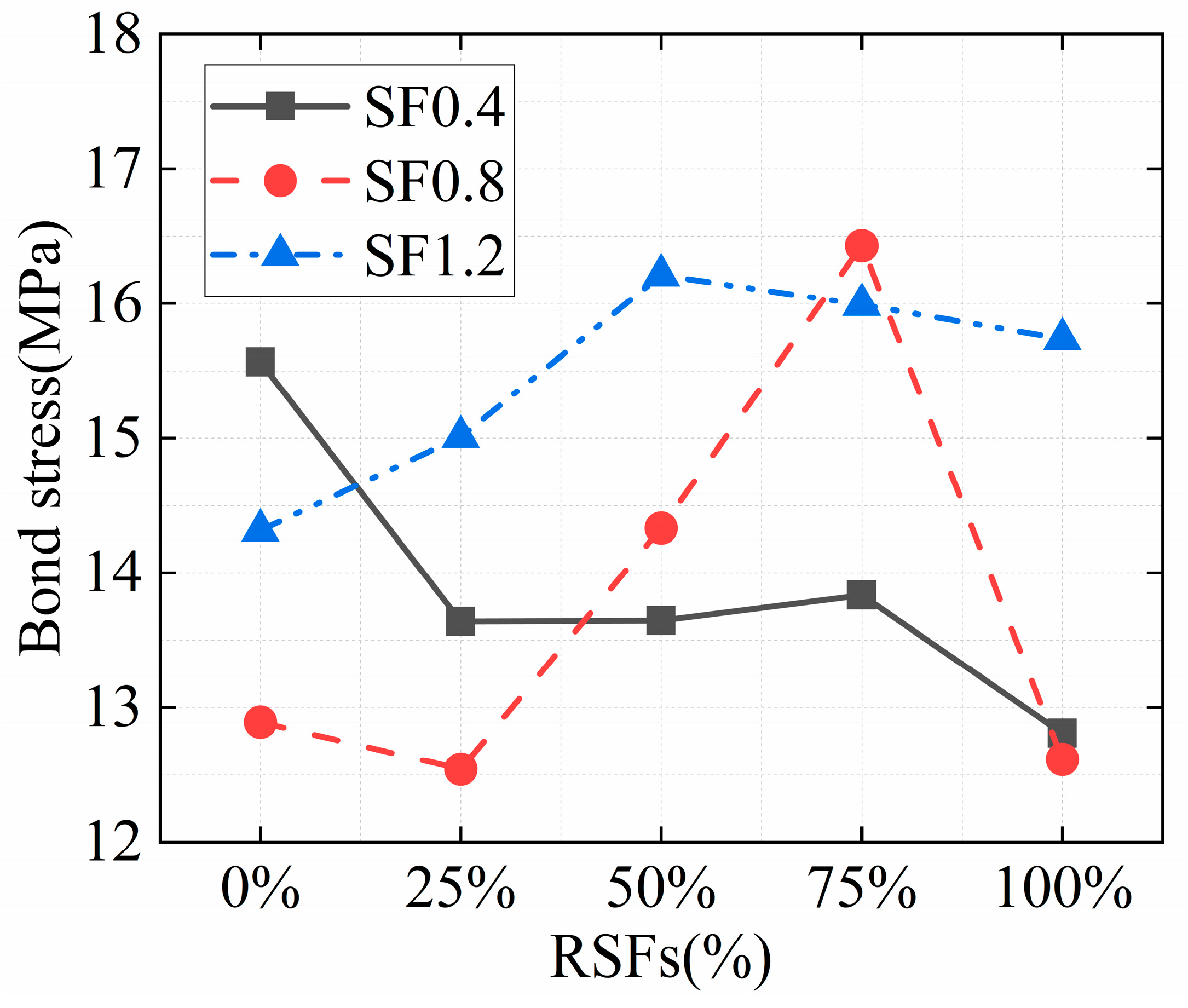
This study assumes that the bond stress in the bond zone is uniformly distributed along the length direction. The pull-out force (F) and the displacement (s′) of the loading end during the test were directly measured by the testing machine. The bond stress (τ) and slip (s) were then obtained by converting Formulas (2) and (3), respectively. Notably, the calculation of s takes into account the deformation of the steel bar:
τ = F π d o l a
s = s L F E f A f
where the d0, la, Ef, and Af are the diameter, bond length, elastic modulus, and cross-sectional area of the steel bar, respectively; L is the length from the loading end of the steel bar to the midpoint of the bond area.
The bond stress–slip curves of the three specimens for each mix ratio are similar. Therefore, only the average bond stress–slip curves of the three specimens for each mix ratio are presented in Figure 7. All specimens obtained a complete bond stress–slip curve, which includes linear ascending segment, nonlinear ascending segment, descending segment, and residual segment. This indicates that the bond between steel and concrete in this study is fully utilized. From the initial slip between steel and concrete until about 70% of the peak bond stress, this stage represents the linear ascending segment of the curve. During this stage, there is a linear positive correlation between the bond stress and slip, and small radial-transverse cracks start to appear at the concrete bond interface. Then, the curve enters the nonlinear ascending segment until the bond stress reaches its peak. During this stage, cracks gradually develop in the concrete and the friction coefficient between the steel bar and the concrete reduces due to the presence of broken concrete powder in the bonding interface. As a result, the slope of the curve continuously decreases until it reaches zero. Subsequently, there is a significant increase in the slip of the steel bar and more severe concrete damage between the ribs, leading to a continuous decline in bond stress. This forms a descending segment of the curve. Eventually, the inter-ribbed concrete is completely cut off and the broken concrete powder forms a new interface at the bonding interface. At this point, there is still some friction on the interface, which tends to stabilize. Therefore, the curve in this stage becomes gentler, representing the residual segment of the curve.
In addition, the effects of RPs, SSFs, and RSFs on the bond–slip curves are shown in Figure 7. Specifically, Figure 7a demonstrates the impact of adding 20% RPs to the bond–slip curve. It can be observed that the inclusion of 20% RPs leads to a significant decrease in the peak value of the bond stress on the curve, as well as a reduction in the slope of the rising section. This phenomenon can be attributed to the fact that the incorporation of RPs results in a decrease in the strength of concrete. RPs are hydrophobic-based materials, while concrete is hydrophilic-based. This difference in properties leads to poor bonding performance between RPs and concrete, resulting in a weak bonding interface. Additionally, RPs and concrete have different hardness and elastic modulus. Under load, stress concentration tends to occur around RPs, leading to a decrease in concrete strength. Figure 7b,c demonstrates the impact of different SF content on the bond stress–slip curve when SSFs and RSFs are added individually. When the SSF content is 0.4% and the RSF content is 1.2%, the peak value of the curve is comparable to that of the reference group (R20S0RS0). However, for other dosages, the curve tends to flatten and the peak value decreases to varying extents. This indicates that the distribution of SFs in concrete plays a crucial role in maintaining the uniformity and compactness of the internal interface of RRAC. Figure 7d,f illustrates the impact of the RSF dosage on the bond stress–slip curve at different SF content. At an SF content of 0.4%, the peak value of the curve decreases to varying degrees after the addition of RSFs, and the wrapping area of the curve is smaller compared to R20S0.4RS0. When the SF content is 0.8%, the peak value of the curve initially decreases, then increases, and finally decreases again with the increase in the proportion of RSFs. For the proportion of RSFs of 50% and 75%, the peak value of the curve is higher than that of specimen R20S0.8RS0. When the content of SF is 1.2%, the peak value and wrapping area of the curve are always greater than that of R20S1.2RS0, regardless of the proportion of RSFs. Moreover, as the proportion of RSFs increases, the overall curve initially rises and then falls. This indicates that the proportion of RSFs has a significant impact on the bonding effect between RRAC and steel bars, depending on the change in SF content. There exists an optimal SF content and RSF ratio, which provides the best enhancement effect on the bonding effect between RRAC and steel bars.

3.4. Bond Strength

The bond strength of the specimen is determined by the peak value of the bond stress–slip curve in this study. The bond strength is calculated by taking the average value of the three specimens in each mix proportions, and the bond strength and their average values are presented in Table 3. The bond strength of specimen R20S0RS0 decreased by 32.87% when compared to ordinary RAC without RPs. This decrease can be attributed to the introduction of defects in the concrete by RPs, which in turn reduces the compressive strength of the concrete [38]. Consequently, the bond strength between the concrete and the steel bars is also reduced. Figure 8 shows the impact of the SF and RSF dosages on bond strength. When solely SSFs were utilized with a 0.4% content, there was a slight enhancement in bond strength in comparison to specimen R20S0RS0. However, as the SSF content increased to 0.8% and 1.2%, the bond strength decreased by 16.41% and 7.13%, respectively, when compared to specimen R20S0RS0. The results demonstrate that the addition of an optimal amount of SSFs enhances the bond strength between RRAC and steel bars. However, excessive incorporation of SSFs can lead to varying degrees of negative effects on the bond strength. This phenomenon can be attributed to the bridging effect of SSFs in the concrete, which restricts the formation of internal cracks. Consequently, SSFs contribute to crack resistance and shear resistance, ultimately improving the bond strength. However, when the content of SSFs is too large, the distribution of SSFs in concrete is not uniform, which results in a decrease in the density of the concrete and the formation of a weak layer. As a result, the negative effect of SSFs outweighs the positive effect, leading to varying degrees of decrease in bond strength of the specimens. When RSFs are solely used at a content of 0.4% and 0.8%, the bond strength is reduced by 16.93% and 18.22% respectively, compared to specimen R20S0RS0. However, when the RSF content is increased to 1.2%, the bond strength is increased by 2.07%. This contrasting result of the sole use of SSFs suggests that the mechanisms of RSFs and SSFs differ, thus supporting the analysis presented in Section 3.2. Notably, the positive impact of RSFs on bond strength is only observed when a sufficient amount of RSFs is present to create numerous closed bodies within the concrete. Otherwise, the negative effect caused by the introduction of significant defects by RSFs continues to prevail.
When the SF content is 0.4%, the bond strength decreases as the RSF ratio increases. However, when the SF content is 0.8% and 1.2%, the bond strength initially increases and then decreases with the increase in the ratio of RSFs. These findings suggest that when the amount of SFs is sufficient, the combined use of SSFs and RSFs is more effective than when using them individually to enhance the bond strength of the concrete. Additionally, incorporating too many RSFs may reduce the density of the concrete and decrease the bond strength due to uneven distribution. This suggests that there is an optimal ratio of SFs to RSFs. The maximum bond strength is achieved when the SF content is 0.8% and 1.2%, with RSF ratios of 75% and 50%, respectively. These ratios result in a bond strength that is 6.55% and 5.12% higher than that of specimen R20S0RS0. Therefore, this study concludes that the optimal content of SSFs and RSFs to enhance bond strength synergistically is 0.8% of the total SF content, with RSFs accounting for 75%.

3.5. Bond Stiffness

The bond stiffness is a measure of the ability to resist the initial relative slip between the concrete and the steel bars. In this study, the secant stiffness at 50% peak bond stress is defined as the bond stiffness, which is the ratio of bond stress to slip at 50% peak bond stress. Table 4 shows the bond stiffness of all the specimens, with the bond stiffness of each mix proportions being the average of the bond stiffness of the three specimens in the group, placed in the last column of the table. Comparing the bonding stiffness of specimens R0S0RS0 and R20S0RS0, it is evident that the bonding stiffness decreased by 37.26% after adding 20% RPs to RAC. This decrease can be attributed to the increased likelihood of cracks forming along the interface between RPs and concrete, which accelerates the rate of concrete deformation. On the other hand, as SFs are incorporated, regardless of the SF to RSF ratio, the bond stiffness is greater than that of specimen R20S0RS0. Furthermore, the bond stiffness increases with higher SF content. This demonstrates that the inclusion of SFs can significantly enhance the bond stiffness between RRAC and steel bars. This improvement is due to the ability of SFs to resist crack development and delay the speed of concrete crushing in the concrete.
Figure 9 illustrates the impact of the SF content and RSF ratio on bond stiffness. When comparing the three curves of SF content at 0.4%, 0.8%, and 1.2%, it can be observed that as the RSF ratio increases from 0% to 100%, the bonding stiffness slightly decreases when the SF content is 0.4%. Throughout this process, the bonding stiffness decreases by 5.47%. On the other hand, when the content of SFs is 0.8%, the bonding stiffness remains relatively unchanged as the proportion of RSFs increases. However, when the SF content is 1.2%, the bonding stiffness noticeably increases with the increase of RSF ratio. This is consistent with the impact of RSFs on the bond strength (mentioned in Section 3.4). It emphasizes that for RSFs to effectively improve bond stiffness, there needs to be a sufficient number of RSFs present. It is important to note that when the SF content is 1.2%, the RSF ratio increases from 75% to 100%, resulting in a 13.88% decrease in bonding stiffness. This indicates that an excessive amount of RSFs has a negative impact on bond stiffness. The reason for this is that the defects introduced by RSFs alone, as well as their excessive use, are too large. This leads to an increase in the number of cracks in the weak layer of the interface between RSFs and concrete, accelerating their development. In addition to that, when the SF content is 1.2%, the bonding stiffness of SSFs and RSFs is considerably enhanced in comparison to that of SSFs or RSFs individually. This finding suggests the presence of a synergistic effect between SSFs and RSFs, with the combined effect of SSFs and RSFs on improving bond stiffness surpassing that of SSFs and RSFs individually. The synergistic effect of SSFs and RSFs can be attributed to the bridging effect of SSFs, which effectively delays the development of concrete cracks around RSFs. Additionally, the concrete area not crossed by SSFs is well protected due to the hooping effect of RSFs. In this study, it was found that when the SF content is 1.2% and the RSF ratio is 75%, the bond stiffness of the specimen is the highest, exhibiting a 53.88% increase compared to specimen R20S0RS0.
The experimental results mentioned above provide evidence of a positive synergistic effect between SSFs and RSFs, which helps in restraining the cracking of RRAC. However, it is important to note that the RSFs used in this study had a smooth surface, and it is uncertain whether this limiting effect will continue to increase with higher substitution ratios of RSFs. To address this concern, introducing textures to the surface of RSFs or exploring the use of ring fibres made from alternative materials could potentially alleviate this issue. In addition, the use of RPs in RRAC results in a weak interfacial transition zone. However, the performance of RRAC can be enhanced by the bridge effect of SSFs. On the other hand, RSFs are effective in limiting the cracking of RRAC. This strengthening effect significantly improves the bonding between RRAC and steel bars.

4. Bond–Slip Constitutive Model

As stated in Section 3.3, the bond stress–slip curves of RRAC and steel bars in this study consist of four sections (i.e., linear ascending segment, nonlinear ascending segment, descending segment, and residual segment). After comparing the bond–slip constitutive models proposed by various researchers, the bond–slip constitutive model of this study was developed based on Xiong [42], Mo [43], and Guo [44]. The curve of the bond–slip constitutive model is illustrated in Figure 10. This curve is divided into three sections: the linear ascending segment from (0, 0) to (Sr, τr), the nonlinear ascending segment from (Sr, τr) to (Su, τu), and the descending segment after (Su, τu). The calculation model is as follows:
τ = K S S S r τ u S S u α S r S S u τ u S / S u β ( S / S u 1 ) 2 + S / S u S u S
α = ln τ u ln τ r ln S u ln S r
where K is the slope of the linear ascending segment, which is defined as the secant stiffness at 50% peak bond stress (obtained from the bond stiffness values measured in Section 3.5), τu is the bond stress corresponding to the peak point of the bond stress–slip curve, Su and τu are the bond slip during the linear ascending segment, τr is the bond stress corresponding to the 70% peak bond stress of the linear ascending segment of the bond stress–slip curve, Sr and τr are the corresponding bond slip, α is the undetermined coefficient of the nonlinear ascending segment (obtained from Formula (5)), β is the undetermined coefficient of the descending segment (obtained from the software fitting).
The bond stiffness value obtained in Section 3.5 is used as K in this study. As the linear rising section and the nonlinear rising section are continuous at (Sr, τr), the value of α can be determined using Formula (5). Additionally, by fitting the data of the descending curve, the value of β can be obtained. The values of relevant parameters and undetermined coefficients are presented in Table 5. The fitting correlation coefficient R2 of β in each group was found to be greater than 0.96, and the standard error SE was less than 0.03. The undetermined coefficients and related parameters from Table 5 are incorporated into the constitutive model (4), resulting in the bond–slip constitutive model for each group. This model is then compared with the bond–slip curve obtained from the test, as shown in Figure 11. It can be observed that the model curve aligns well with the test curve, indicating the high accuracy of the bond–slip constitutive model proposed in this study. Notably, the proposed bond–slip constitutive model is specifically designed for analysing steel bar pull-out failure, it may not be suitable for cases where the failure mode involves concrete cracking or steel breaking.

5. Conclusions

In this study, a central pull-out test was conducted on 51 pull-out specimens to investigate the impact of the content of SSFs and RSFs on the bonding properties of RRAC and steel bars. The main conclusions can be drawn as follows:
(1)
The failure of reinforced inter-rib concrete after extrusion is crucial for the failure of RRAC and steel bar bonding. The combined use of SSFs and RSFs inhibits crack development of RRAC, delays damage to the inter-ribbed concrete matrix, and enhances the bonding effect between RRAC and steel bars. However, excessive SFs can reduce the compactness of concrete and create a weak layer at the interface between SFs and concrete, which negatively affects the bonding effect. In practical applications, it is recommended to limit the steel fibre content to below 1.2% and control the water–cement ratio of concrete.
(2)
After the addition of 20% RPs, the bond strength experienced a decrease of 32.87%. When only SSFs or RSFs were added, the bond strength showed improvement with the addition of 0.4% SSFs or 1.2% RSFs, while other dosages resulted in varying degrees of bond-strength decrease. There is a synergistic effect between SSFs and RSFs, and the best improvement in bond strength is achieved through their combined use. When the SF content is 0.8% and the RSF ratio is 75%, the bond strength reaches its maximum value, which is 6.55% higher than that of specimen R20S0RS0.
(3)
The bonding stiffness decreased by 37.26% after adding 20% RPs. However, the bonding stiffness improved when SFs were added, regardless of changes in content. The improvement effect becomes more apparent as the SF content increases. The bonding stiffness reaches its maximum at a 1.2% SF content and a 75% RSF ratio, which is 53.88% higher than that of the R20S0RS0 specimen. Considering both bonding strength and bonding stiffness, the optimal mix ratio to enhance the bonding effect between RRAC and steel bars is a 1.2% SF total content and a 75% RSF ratio.
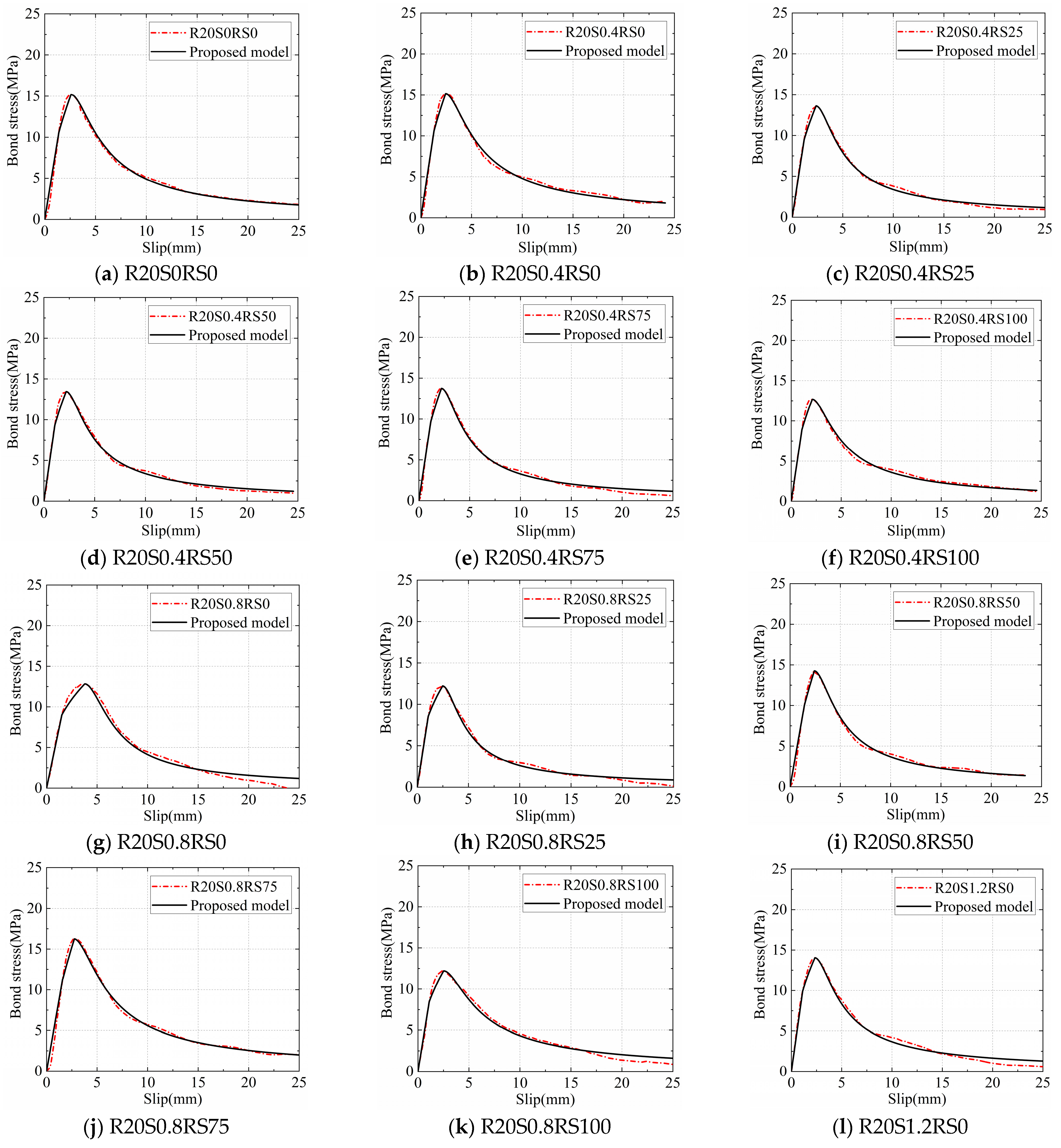
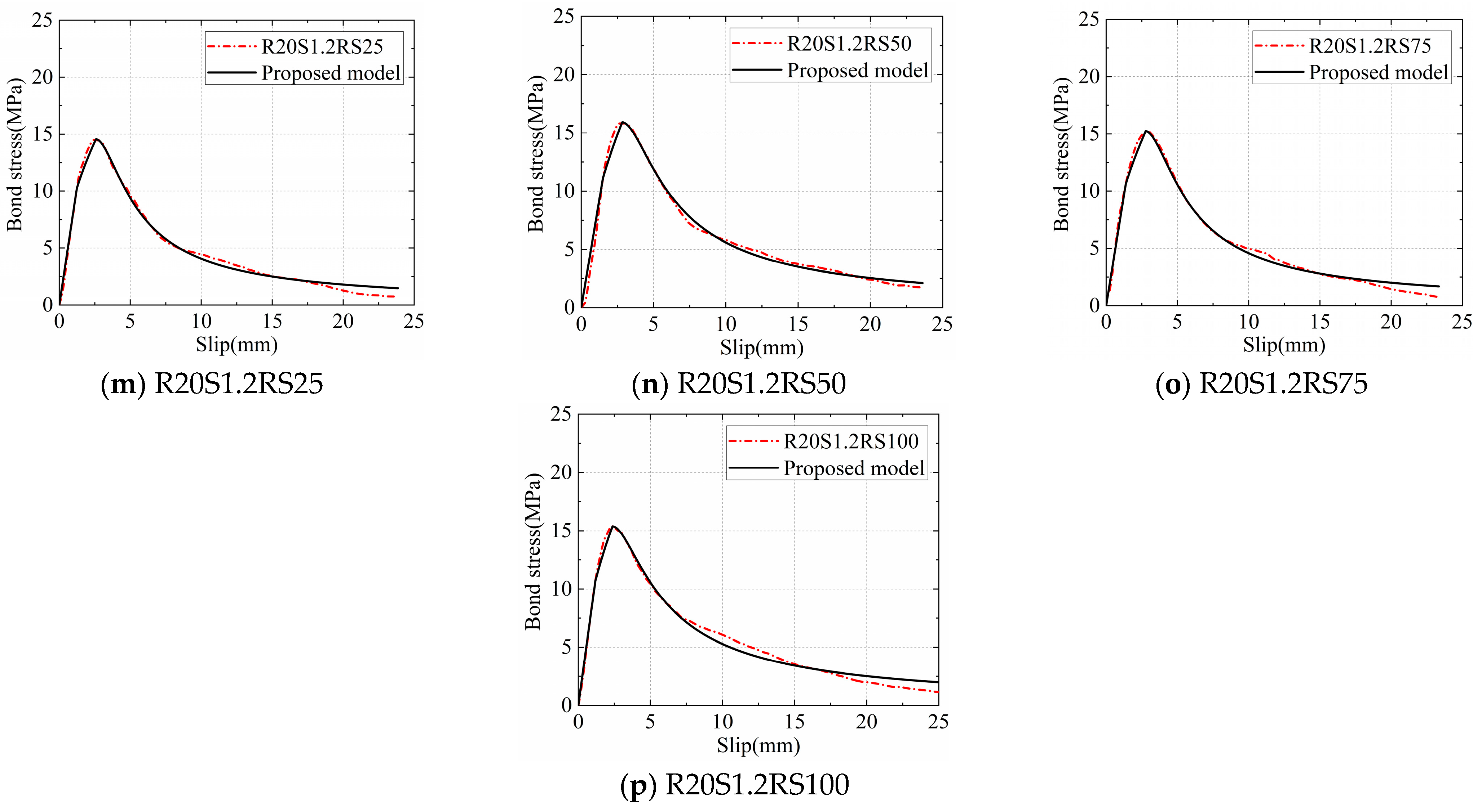
(4)
The bond–slip constitutive model of RRAC and steel bars was established based on the characteristics of the bond stress–slip curve. The model shows excellent agreement with the experimental data and can accurately predict the bond stress–slip relationship between RRAC and steel bars.

Author Contributions

Conceptualization, F.L.; methodology, S.H.; validation, J.Z.; formal analysis, H.L., W.W. and X.T.; investigation, J.Z. and X.L.; resources, F.L.; data curation, H.M.; writing—original draft preparation, H.L.; writing—review and editing, H.M.; visualization, S.H.; supervision, F.L.; project administration, W.W. All authors have read and agreed to the published version of the manuscript.

Funding

The authors gratefully acknowledge the financial support provided by the National Natural Science Foundation of China under Grant No. 12072080 and Grant No. 12032009.

Data Availability Statement

The raw data supporting the conclusions of this article will be made available by the authors on request.

Conflicts of Interest

Author Honglong Ma was employed by the company China Railway 17th Bureau Group Co., Ltd. and Xiaopeng Tian was employed by the company China Railway 17th Bureau Group (Guangzhou) Construction Co., Ltd. The remaining authors declare that the research was conducted in the absence of any commercial or financial relationships that could be construed as a potential conflict of interest.

References

  1. Mai, G.H.; Li, L.J.; Lin, J.W.; Wei, W.; He, S.H.; Zhong, R.K.; Xiong, Z. Bond durability between BFRP bars and recycled aggregate seawater sea-sand concrete in freezing-thawing environment. J. Build. Eng. 2023, 70, 106422. [Google Scholar] [CrossRef]
  2. Zhu, X.Y.; Jiang, Z.M. Reuse of waste rubber in pervious concrete: Experiment and DEM simulation. J. Build. Eng. 2023, 71, 106452. [Google Scholar] [CrossRef]
  3. Xiong, Z.; Wei, W.; Liu, F.; Cui, C.Y.; Li, L.J.; Zou, R.; Zeng, Y. Bond behaviour of recycled aggregate concrete with basalt fibre-reinforced polymer bars. Compos. Struct. 2021, 256, 113078. [Google Scholar] [CrossRef]
  4. Wang, W.D.; Lu, C.X.; Zhu, Z.M.; Zhang, Z.Y.; Liu, S.Y.; Ji, Y.C.; Xing, Z.Q. Mechanical performance of recycled aggregate concrete in green civil engineering: Review. Case Stud. Constr. Mat. 2023, 19, e02384. [Google Scholar] [CrossRef]
  5. Formela, K. Waste tire rubber-based materials: Processing, performance properties and development strategies. Adv. Ind. Eng. Polym. Res. 2022, 5, 234–247. [Google Scholar] [CrossRef]
  6. Tang, Y.C.; Feng, W.H.; Feng, W.X.; Chen, J.M.; Bao, D.J.; Li, L.J. Compressive properties of rubber-modified recycled aggregate concrete subjected to elevated temperatures. Constr. Build. Mater. 2021, 268, 121181. [Google Scholar] [CrossRef]
  7. Zhu, H.Y.; Xiong, Z.; Song, Y.Y.; Zhou, K.T.; Su, Y. Effect of expansion agent and glass fiber on the dynamicsplitting tensile properties of seawater–sea-sand concrete. Buildings 2024, 14, 217. [Google Scholar] [CrossRef]
  8. Pan, Z.Z.; Liu, F.; Li, H.W.; Li, X.H.; Wang, D.C.; Ling, Z.; Zhu, H.Y.; Zhu, Y.H. Performance evaluation of thermal insulation rubberized mortar modified by fly ash and glass fiber. Buildings 2024, 14, 221. [Google Scholar] [CrossRef]
  9. Zhen, H.; Xiong, Z.; Song, Y.Y.; Li, L.J.; Qiu, Y.; Zou, X.Z.; Chen, B.; Chen, D.G.; Liu, F.; Ji, Y.D. Early mechanical performance of glass fibre-reinforced manufactured sand concrete. J. Build. Eng. 2024, 83, 108440. [Google Scholar] [CrossRef]
  10. El-Zohairy, A.; Sanchez, M.; Abediniangerabi, B.; Moler, P. Performance of rubberized concrete and the effect of temperature and stainless steel fibers. Buildings 2023, 12, 280. [Google Scholar] [CrossRef]
  11. Eisa, A.S.; Elshazli, M.T.; Nawar, M.T. Experimental investigation on the effect of using crumb rubber and steel fibers on the structural behavior of reinforced concrete beams. Constr. Build. Mater. 2020, 252, 119078. [Google Scholar] [CrossRef]
  12. Guo, Y.C.; Zhanng, J.H.; Chen, G.; Chen, G.M.; Xie, Z.H. Fracture behaviors of a new steel fiber reinforced recycled aggregate concrete with crumb rubber. Constr. Build. Mater. 2014, 53, 32–39. [Google Scholar] [CrossRef]
  13. Chen, A.J.; Han, X.Y.; Chen, M.; Wang, X.Y.; Wang, Z.H.; Guo, T.T. Mechanical and stress-strain behavior of basalt fiber reinforced rubberized recycled coarse aggregate concrete. Constr. Build. Mater. 2020, 260, 119888. [Google Scholar] [CrossRef]
  14. Mohseni, E.; Koushkbaghi, M. Recycling of landfill waste tyre in construction materials: Durability of concrete made with chipped rubber. Constr. Build. Mater. 2023, 409, 134114. [Google Scholar] [CrossRef]
  15. Xiong, Z.; Fang, Z.; Feng, W.H.; Liu, F.; Yang, F.; Li, L.J. Review of dynamic behaviour of rubberised concrete at material and member levels. J. Build. Eng. 2021, 38, 102237. [Google Scholar] [CrossRef]
  16. Guo, Y.C.; Zhang, J.H.; Chen, G.M.; Xie, Z.H. Compressive behaviour of concrete structures incorporating recycled concrete aggregates, rubber crumb and reinforced with steel fibre, subjected to elevated temperatures. J. Clean. Prod. 2014, 72, 193–203. [Google Scholar] [CrossRef]
  17. Shahjalal, M.; Islam, K.; Batool, F.; Tiznobaik, M.; Hossain, Z.F.M.; Ahmed, K.S.; Alam, S.M.; Ahsan, R. Fiber-reinforced recycled aggregate concrete with crumb rubber: A state-of-the-art review. Constr. Build. Mater. 2023, 404, 133233. [Google Scholar] [CrossRef]
  18. Gholampour, A.; Ozbakkaloglu, T.; Hassanli, R. Behavior of rubberized concrete under active confinement. Constr. Build. Mater. 2017, 138, 372–382. [Google Scholar] [CrossRef]
  19. Chen, F.; Wu, K.; Ren, L.J.; Xu, J.N.; Zheng, H.M. Internal curing effect and compressive strength calculation of recycled clay brick aggregate concrete. Materials 2019, 12, 1815. [Google Scholar] [CrossRef]
  20. Zrar, Y.J.; Younis, K.H.; Sherwani, A.F.H. Properties of sustainable self-compacted concrete with recycled concrete and waste tire crumb rubber aggregates. Constr. Build. Mater. 2023, 407, 133524. [Google Scholar] [CrossRef]
  21. Liu, F.; Meng, L.Y.; Ning, G.F.; Li, L.J. Fatigue performance of rubber-modified recycled aggregate concrete (RRAC) for pavement. Constr. Build. Mater. 2015, 95, 207–217. [Google Scholar] [CrossRef]
  22. Saberian, M.; Tajaddini, A.; Li, J.; Zhang, G.M.; Wang, L.; Sun, D.A.; Maqsood, T.; Roychand, R. Mechanical properties of polypropylene fibre reinforced recycled concrete aggregate for sustainable road base and subbase applications. Constr. Build. Mater. 2023, 405, 133352. [Google Scholar] [CrossRef]
  23. Peng, S.; Wu, B.; Du, X.Q.; Zhao, Y.F.; Yu, Z.P. Study on dynamic splitting tensile mechanical properties and microscopic mechanism analysis of steel fiber reinforced concrete. Structures 2023, 58, 105502. [Google Scholar] [CrossRef]
  24. Han, J.H.; Zhao, M.M.; Chen, J.Y.; Lan, X.F. Effects of steel fiber length and coarse aggregate maximum size on mechanical properties of steel fiber reinforced concrete. Constr. Build. Mater. 2019, 209, 577–591. [Google Scholar] [CrossRef]
  25. Li, Q.Y.; Shi, Z.M.; Zhao, F.; Yu, S.B.; Xie, K.L. Mechanical performance evaluation of steel fiber-reinforced concrete (FRC) based on multi-mechanical indicators from split hopkinson pressure bar (SHPB) test. J. Build. Eng. 2023, 79, 107898. [Google Scholar] [CrossRef]
  26. Olivito, R.S.; Zuccarello, F.A. An experimental study on the tensile strength of steel fiber reinforced concrete. Compos. Part B-Eng. 2010, 41, 246–255. [Google Scholar] [CrossRef]
  27. Xie, J.H.; Li, J.L.; Lu, Z.Y.; Li, Z.J.; Fang, C.; Huang, L.; Li, L.J. Combination effects of rubber and silica fume on the fracture behaviour of steel-fibre recycled aggregate concrete. Constr. Build. Mater. 2019, 203, 164–173. [Google Scholar] [CrossRef]
  28. Xue, G.J.; Wang, C.L.; Zhang, J.M.; Liu, Z.P.; Zhang, T.T.; Zhang, Y.X. Influence of steel fiber shape on the performance of high-performance concrete. Acta Mater. Compos. Sin. 2021, 38, 43413–44324. [Google Scholar]
  29. Lee, C.; Kim, H. Orientation factor and number of fibers at failure plane in ring-type steel fiber reinforced concrete. Cement Concrete Res. 2010, 40, 810–819. [Google Scholar] [CrossRef]
  30. Choia, O.C.; Lee, C. Flexural performance of ring-type steel fiber-reinforced concrete. Cem. Concr. Res. 2003, 33, 841–849. [Google Scholar] [CrossRef]
  31. He, S.H.; Li, L.J.; Xiong, Z.; Zhang, H.Q.; Zheng, J.H.; Su, Y.; Huang, J.; Liu, F. Effects of ring-type and straight steel fibres on the compressive performance of rubber-recycled aggregate concrete. J. Build. Eng. 2023, 76, 107148. [Google Scholar] [CrossRef]
  32. Zheng, Y.X.; Fang, C.C.; Ma, J.J.; Wang, S.Q. Review of research on Bond-Slip of reinforced concrete structures. Constr. Build. Mater. 2023, 385, 131437. [Google Scholar] [CrossRef]
  33. Li, L.G.; Chen, Z.P.; Ouyang, Y.; Zhu, J.; Chu, S.H.; Kwan, A.K.H. Synergistic effects of steel fibres and expansive agent on steel bar-concrete bond. Cem. Concr. Comp. 2019, 104, 103380. [Google Scholar] [CrossRef]
  34. Vedernikov, A.; Gemi, L.; Madenci, E.; Onuralp Özkılıç, Y.; Yazman, Ş.; Gusev, S.; Sulimov, A.; Bondareva, J.; Evlashin, S.; Konev, S.; et al. Effects of high pulling speeds on mechanical properties and morphology of pultruded GFRP composite flat laminates. Compos. Struct. 2022, 301, 116216. [Google Scholar] [CrossRef]
  35. Vedernikov, A.; Tucci, F.; Carlone, P.; Gusev, S.; Konev, S.; Firsov, D.; Akhatov, I.; Safonov, A. Effects of pulling speed on structural performance of L-shaped pultruded profiles. Compos. Struct. 2021, 255, 112967. [Google Scholar] [CrossRef]
  36. Huang, Y.; Yu, Z.F. Experimental study of the bonding behavior between coarse aggregate ultra-high performance concrete and steel rebar. Eng. Struct. 2023, 288, 116253. [Google Scholar] [CrossRef]
  37. Gao, K.; Li, H.; Liu, G.G.; Huang, Z.Y.; Wu, G.B. Bonding properties between steel-basalt hybrid fibers reinforced cementitious composites and existing concrete at high temperatures. J. Build. Eng. 2023, 70, 106371. [Google Scholar]
  38. Garcia-Taengua, E.; Martí-Vargas, J.R.; Serna, P. Bond of reinforcing bars to steel fiber reinforced concrete. Constr. Build. Mater. 2016, 105, 275–284. [Google Scholar] [CrossRef]
  39. Dancygier, A.N.; Katz, A.; Wexler, U. Bond between deformed reinforcement and normal and high-strength concrete with and without fibers. Mater. Struct. 2010, 43, 839–856. [Google Scholar] [CrossRef]
  40. Bao, S.H.; Zhang, Y.F.; Li, C.B.; Zhang, W.J.; Zeng, K. Interfacial bonding behavior of steel fibers when using fine glass powder as partial substitution of silica fume/cement. Constr. Build. Mater. 2024, 411, 134516. [Google Scholar] [CrossRef]
  41. Majain, N.; Rahman, A.B.A.; Adnan, A.; Mohamed, R.N. Bond behaviour of deformed steel bars in steel fibre high-strength self-compacting concrete. Constr. Build. Mater. 2022, 318, 125906. [Google Scholar] [CrossRef]
  42. Xiong, Z.; Zeng, Y.; Li, L.G.; Kwan, A.K.H.; He, S.H. Experimental study on the effects of glass fibres and expansive agent on the bond behaviour of glass/basalt FRP bars in seawater sea-sand concrete. Constr. Build. Mater. 2021, 274, 122100. [Google Scholar] [CrossRef]
  43. Mo, K.H.; Visintin, P.; Alengaram, U.J.; Jumaat, M.Z. Bond stress-slip relationship of oil palm shell lightweight concrete. Eng. Struct. 2016, 127, 319–330. [Google Scholar] [CrossRef]
  44. Guo, Z.H. The Strength and Deformation Test Basis and Constitutive Relationship of Concrete; Tsinghua University Press: Beijing, China, 1997. [Google Scholar]
Figure 1. Particle size distribution of aggregates. (a) Sand, (b) RCA.
Buildings 14 00504 g001
Figure 2. Geometry size of SSFs and RSFs. (a) SSFs, (b) RSFs.
Buildings 14 00504 g002
Figure 3. The steel mould and process for making pull-out specimens.
Buildings 14 00504 g003
Figure 4. Test setup and machine.
Buildings 14 00504 g004
Figure 5. Bond interface damage. (a) 0% SFs, (b) 100% SSFs, (c) SSFs + RSFs (with any replacement ratio), (d)100% RSFs.
Buildings 14 00504 g005
Figure 6. Effects of SSFs and RSFs on bond mechanism. (a) Legend, (b) RRAC reinforced with SSFs, (c) enclosure inside RSFs, (d) RRAC reinforced with RSFs, (e) RRAC reinforced with RSFs and SSFs.
Buildings 14 00504 g006aBuildings 14 00504 g006b
Figure 7. Bond stress–slip curves. (a) Effects of 20% of RPs, (b) effects of SSFs with different contents, (c) effects of RSFs with different contents, (d) effects of 0.4% SFs with different RSF proportions, (e) effects of 0.8% SFs with different RSF proportions, (f) effects of 1.2% SFs with different RSF proportions.
Buildings 14 00504 g007
Figure 8. Bond strength results.
Buildings 14 00504 g008
Figure 9. Bond stiffness results.
Buildings 14 00504 g009
Figure 10. Bond–slip constitutive relationship model.
Buildings 14 00504 g010
Figure 11. Comparations between the experimental curve and proposed model (the relative parameters are mentioned in Table 5).
Buildings 14 00504 g011aBuildings 14 00504 g011b
Table 1. Properties of steel fibres applied in this study.
Fibre TypeRaw MaterialShape FeatureTensile Strength fst (MPa)Apparent Density ρ (kg/m3)Elastic Modulus Es (GPa)
SSFsCarbon steelHooked-end
steel fibre
10007436200
RSFsStainless steelRing-shape
steel fibre
9607600193
Table 2. Mix proportions.
Mix NumberCement
(kg/m3)
Water
(kg/m3)
Sand
(kg/m3)
RCA
(kg/m3)
RPs
(kg/m3)
RSFs
(kg/m3)
SSFs
(kg/m3)
Compressive Strength (MPa)
R0S0RS0596.20228.30791.33742.870.000.000.0045.73
R20S0RS0596.20228.01633.06742.8759.280.000.0037.07
R20S0.4RS0596.20227.88628.84737.9258.880.0029.7435.89
R20S0.4RS25596.20227.88628.84737.9258.887.6022.3136.86
R20S0.4RS50596.20227.88628.84737.9258.8815.2014.8740.08
R20S0.4RS75596.20227.88628.84737.9258.8822.807.4432.44
R20S0.4RS100596.20227.88628.84737.9258.8830.400.0038.30
R20S0.8RS0596.20227.75624.62732.9658.490.0059.4940.26
R20S0.8RS25596.20227.75624.62732.9658.4915.2044.6243.17
R20S0.8RS50596.20227.75624.62732.9658.4930.4029.7439.83
R20S0.8RS75596.20227.75624.62732.9658.4945.6014.8736.18
R20S0.8RS100596.20227.75624.62732.9658.4960.800.0033.03
R20S1.2RS0596.20227.62620.40728.0158.090.0089.2341.25
R20S1.2RS25596.20227.62620.40728.0158.0922.8066.9238.76
R20S1.2RS50596.20227.62620.40728.0158.0945.6044.6238.67
R20S1.2RS75596.20227.62620.40728.0158.0968.4022.3137.42
R20S1.2RS100596.20227.62620.40728.0158.0991.200.00
Note: in specimen “R20S0.4RS25”, “R20” refers to the replacement of fine aggregate by 20% RPs, “S0.4” refers to the total content of SFs being 0.4%, “RS25” refers to the RSFs ratio accounting for 25% of the total content of SFs.
Table 3. Bond strength results.
Concrete Mix No.Bond Strength (MPa)
Specimen 1Specimen 2Specimen 3Mean
R0S0RS022.1524.6722.1022.97
R20S0RS013.8517.3115.1015.42
R20S0.4RS015.5715.7615.3615.56
R20S0.4RS2513.5913.3613.9713.64
R20S0.4RS5012.8313.3214.6813.64
R20S0.4RS7515.2813.7512.4713.83
R20S0.4RS10013.2412.4612.7312.81
R20S0.8RS013.0213.9811.6812.89
R20S0.8RS2513.0611.8612.7112.54
R20S0.8RS5013.5314.5714.9014.33
R20S0.8RS7516.5118.3814.4116.43
R20S0.8RS10012.1213.1712.5512.61
R20S1.2RS012.5014.9315.5114.32
R20S1.2RS2513.7015.1116.2115.01
R20S1.2RS5015.7916.6516.1916.21
R20S1.2RS7515.4216.8115.7515.99
R20S1.2RS10016.1716.8814.1615.74
Table 4. Bond stiffness results.
Concrete Mix No.Bond Stiffness (MPa/mm)
Specimen 1Specimen 2Specimen 3Mean
R0S0RS010.8110.728.029.85
R20S0RS05.056.646.856.18
R20S0.4RS07.637.697.137.49
R20S0.4RS257.606.507.997.36
R20S0.4RS507.276.847.807.30
R20S0.4RS757.347.036.677.01
R20S0.4RS1006.867.327.057.08
R20S0.8RS08.127.727.617.82
R20S0.8RS256.689.487.697.95
R20S0.8RS508.448.107.437.99
R20S0.8RS757.887.898.187.98
R20S0.8RS1007.397.189.007.85
R20S1.2RS07.908.588.058.18
R20S1.2RS257.908.758.448.36
R20S1.2RS508.529.308.558.79
R20S1.2RS759.779.189.579.51
R20S1.2RS1007.458.688.448.19
Table 5. The values of relevant parameters and undetermined coefficients.
Concrete Mix No.KαβR2SE
R20S0RS06.180.57980.99200.99720.0024
R20S0.4RS07.490.56500.92310.99350.0033
R20S0.4RS257.360.52181.21940.99350.0051
R20S0.4RS507.300.51661.06990.99470.0043
R20S0.4RS757.010.55061.17530.99110.0058
R20S0.4RS1007.080.52430.85470.99160.0034
R20S0.8RS07.820.38582.05870.96330.0235
R20S0.8RS257.950.42591.61870.98330.0116
R20S0.8RS507.990.67011.20440.99430.0042
R20S0.8RS757.980.67720.98010.99710.0025
R20S0.8RS1007.850.44560.82290.98120.0053
R20S1.2RS08.180.47201.12650.97960.0086
R20S1.2RS258.360.47691.21010.98850.0064
R20S1.2RS508.790.56641.01610.99480.0033
R20S1.2RS759.510.51521.23320.99000.0061
R20S1.2RS1008.190.52460.78040.97820.0054
R2: coefficient of fitness; SE: standard error.
Disclaimer/Publisher’s Note: The statements, opinions and data contained in all publications are solely those of the individual author(s) and contributor(s) and not of MDPI and/or the editor(s). MDPI and/or the editor(s) disclaim responsibility for any injury to people or property resulting from any ideas, methods, instructions or products referred to in the content.

