Article

Construction Simulation and Monitoring of the Jacking Steel Truss and Main Column of a Super High-Rise Building

1
School of Civil & Architecture Engineering, Xi’an Technological University, Xi’an 710021, China
2
SCEGC No.1 Construction Engineering Group Company Ltd., Xi’an 710068, China
*
Author to whom correspondence should be addressed.
Buildings 2024, 14(3), 617; https://doi.org/10.3390/buildings14030617
Submission received: 5 January 2024 / Revised: 6 February 2024 / Accepted: 9 February 2024 / Published: 26 February 2024
(This article belongs to the Section Building Structures)

Abstract

:
To ensure that the steel truss used in a super high-rise building in Xi’an remains in a safe and reliable state during the construction and jacking process, the jacking steel truss and the main column are studied. A finite element model of the steel truss and the main column is established by using finite element software. The stress values of the steel truss and the main column under various working conditions are simulated, and the stress and perpendicularity of the key points of the structure are monitored via the stress monitoring system under different working conditions. Through the monitoring system, the data on the operation of the steel truss are collected, and the monitoring data are compared with the finite element simulation data to ensure the safe operation of the steel truss. The results indicate that the inclination angle of the main column is easily disturbed by the external environment. The main column is inclined in two directions, but it does not exceed 0.3°, indicating good verticality. The stress monitoring values are generally close to the simulated values. The peak values of the stress at the measuring points during the construction stage are the same as the results obtained from the field test, and the error between the measured maximum stress value and the simulated value is controlled within 10%. In general, the simulated values are in good agreement with the measured values.

1. Introduction

The development of an overall jacking construction platform system and the application of a complete set of comprehensive construction technologies have solved the problems of using complex measures to deal with frequent structural changes, extensive modification, dangerous operation, and a prolonged construction period for the concrete structures of super high-rise buildings. At the same time, they also provide a way to deal with construction problems, such as the high-altitude combination of a scaffold system and formwork, high-altitude conversion, and the inward movement of wall formwork shrinkage, while creating a safe construction environment and working platform for simple core construction. Therefore, the jacking steel truss of a super high-rise building represents the development direction of construction engineering and has guiding significance for similar projects.
Compared with other construction equipment, the jacking steel truss has great advantages in integrity, safety, and the construction period and has become the mainstream method of constructing the core tube structures of super high-rise buildings. Compared with the traditional sliding mode, flipping mode, and climbing mode, the hydraulic jacking formwork has the following advantages:
(1)
Under normal circumstances, the core tube building with a height of more than 350 m is suitable for the overall jacking formwork structure for construction operations. The integral lifting formwork structure is a relatively safe and closed operation system. Its formwork system, hanging system, and steel platform system can be jacked up synchronously. It has many advantages, such as rapid operation, high mechanization, good safety, and low manual consumption.
(2)
There is no need for large-scale assembly or welding at the construction site. This is because the thickness change of the external wall of the building structure is fully considered when formulating the preparation plan of the formwork. When the wall produces a variable cross-section, only part of the formwork can be removed, which greatly improves the reuse rate of the formwork.
(3)
Because of the precise computer control system and hydraulic jacking control device, the formwork structure of the integral lifting steel platform provides strong security for multiple cylinder-lifting operations at the same time.
(4)
The highly mechanized and standardized formwork system reduces the jacking operation of the whole platform structure to only 2 to 3 h and enables 2 to 3 days of construction progress per floor.
(5)
Due to the strong bearing capacity of the integral jacking formwork structure, large distributors and large-tonnage materials can be placed directly on the platform, which can reduce the number of tower cranes and improve construction efficiency.
Reference [1] developed a set of key technologies for steel structure platform systems with multi-functional integration and safety protection and applied them in a project in Shenzhen to improve construction efficiency and high-altitude safety. Reference [2] designed an intelligent jacking steel platform system by taking the T2 tower project of the Dongguan International Trade Center as an example. Through practical application, the system can meet construction requirements. By optimizing this construction technology, the construction progress is significantly improved. In the construction of the jack-up platform, Reference [3] adopted several technical measures to reduce the difficulty in the suspension of the formwork suspension system. By suspending the formwork on the steel beam using high-strength bolts and formwork to fill the adjustment plate, the change in the structural layer height and the wall thickness was effectively dealt with, thus improving the construction adaptability. Reference [4] used ABAQUS software to carry out static analysis on the jack-up steel platform, obtained the stress distribution of the jack-up steel platform under different construction conditions, determined the most unfavorable load position, and optimized the design of the steel platform according to the analysis results. In Reference [5], an intelligent construction machine integrating the attached support and assembled truss was designed. The simulation of the key system of the intelligent construction machine based on the “life and death element method” and the numerical analysis based on the calculated length coefficient method were carried out by finite element software. On this basis, a mathematical optimization model was established to improve the design of steel trusses. Reference [6] introduced the direct analysis method in the Steel Structure Design Standard (GB50017-2017) into the design of a steel frame structure, which has significance for the design of the steel truss construction platform system of an intelligent building machine. Against the background of the China Resources Building, Reference [7] applied BIM technology to the innovative application of the deepening design and construction simulation of a micro-convex fulcrum jacking steel platform to achieve cost savings. Reference [8] simulated the stress and deformation under different working conditions by using finite element software and compared them with the data obtained from field monitoring. It was concluded that the monitoring value was consistent with the simulation value of the finite element software, which provides reliable information for the safe construction of formwork. Through finite element simulation, three-dimensional models under different working conditions were established, the stress analysis of the structure was carried out, and the steel truss was monitored on site to observe the stress of the structure in real time, so as to ensure its safe operation [9,10,11,12]. Based on the Fuzhou Yuyang Central Jinzuo Project, Zhou modeled and numerically analyzed the key systems of the jacking steel truss and carried out on-site monitoring of the steel truss to ensure safe operation during jacking and construction. According to the monitoring results, some suggestions were proposed to ensure construction safety [13]. Gao et al., monitored the deformation of a super high-rise building using vibrating wire strain gauges during the construction of 10 to 48 floors and compared the monitoring results with the numerical analysis results. It was found that the monitoring results were basically consistent with the numerical analysis trend [14].
Taking a super high-rise project in the Yanta District of Xi’an as the subject, this paper uses Midas Gen 2022 to establish a finite element model to simulate and analyze the member stress and the inclination angle of the main column of the jack-up steel platform. The field monitoring data are compared with the simulated values to obtain the degree of agreement between the two stress values, and then the safety evaluation of the project is carried out [15,16,17].

2. Project Overview

The project is located in the #9 building of the A section of a hotel in the Yanta District of Xi’an City, which is a frame-shear wall hybrid structure. The construction area 52 floors above ground is 80,725.52 m2, the construction area 4 floors below ground is 19,206.52 m2, the construction area of a single layer of core tube is 379.5 m2, the building height is 263.35 m, and the highest elevation of the building is 266 m. The standard layer height is 4.2 m. The thickness of the outer wall of the core tube shrinks with height (1100~500 mm), and the structural form of the core tube does not change. From the foundation to the 6 layers of the wall, there are 21, 32, 42, and 43 layers of steel plate walls and 22, 23, 33, 34, 44, and 45 layers of outrigger trusses.
The plane shape of the core tube of the project is rectangular, as shown in Figure 1. The core tube structure gradually shrinks with the increase in height. The single-layer area of the core tube is about 379.5 m2, and the plane size of the core tube is 28.75 m × 13.20 m. The standard layer height of the core tube is 4.2 m, the L01 layer height is 5.48 m, the L01 + layer height is 5.1 m, and the L02 layer height is 5.5 m. The non-standard layers above the L03 layer comprise 4.3 m (L10, L32, L43), 5.7 m (L11, L22, L33, L44), 5.6 m (L21), 2.15 m (L32+), 6.35 m (L47), 4.0 m (L48, L49), 3.5 m (L48+, L49+), 5.2 m (L51, L52), and 5.75 m (roof). The thickness of the outer wall of the core tube is mainly divided into sections of 1200 mm (below L01+), 1100 mm (below L12), 900 mm (below L17), 800 mm (below L23), 700 mm (below L28), 600 mm (below L34), and 500 mm (above L35). The core tube wall shrinks by 700 mm and is mainly C60 concrete pouring.

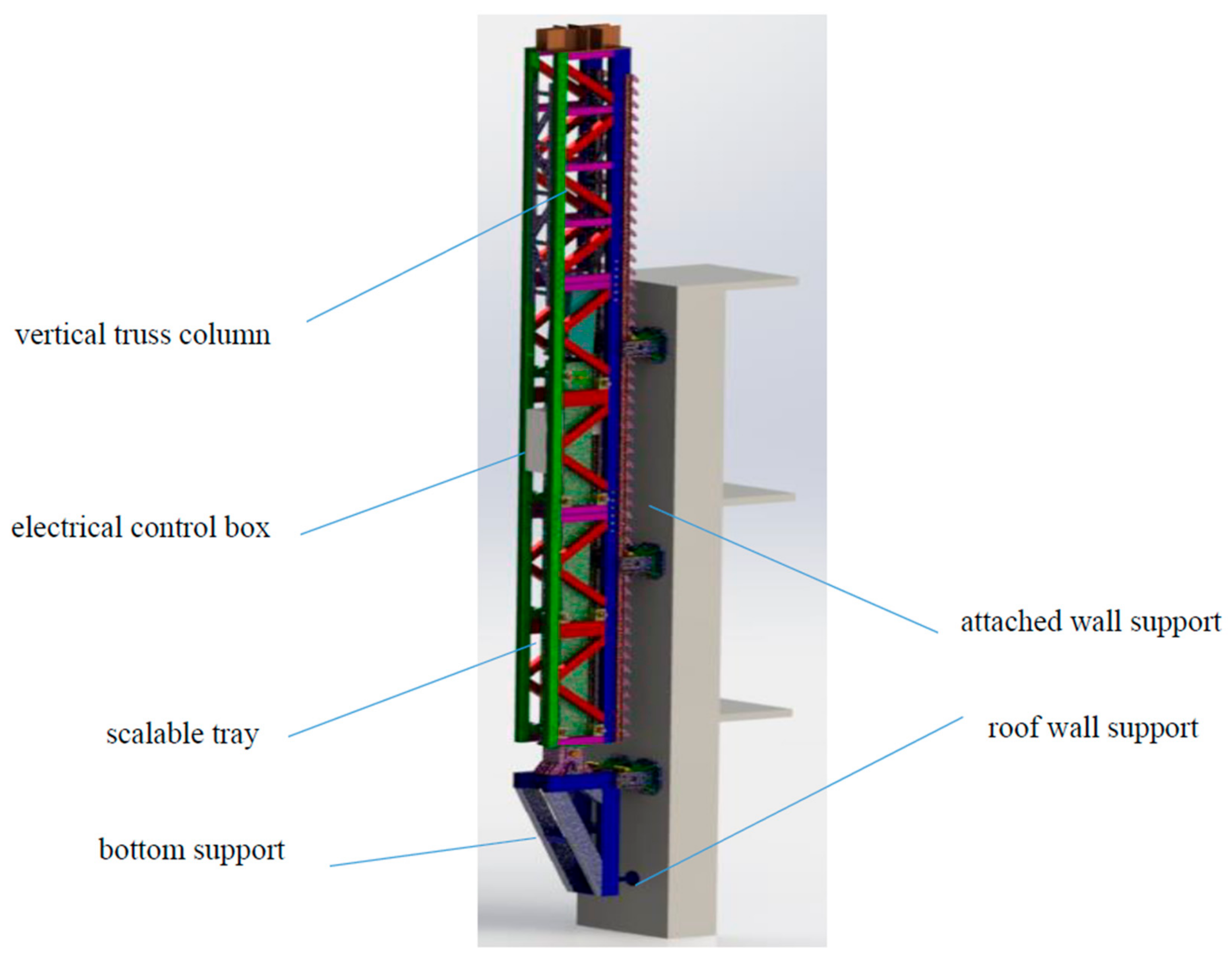
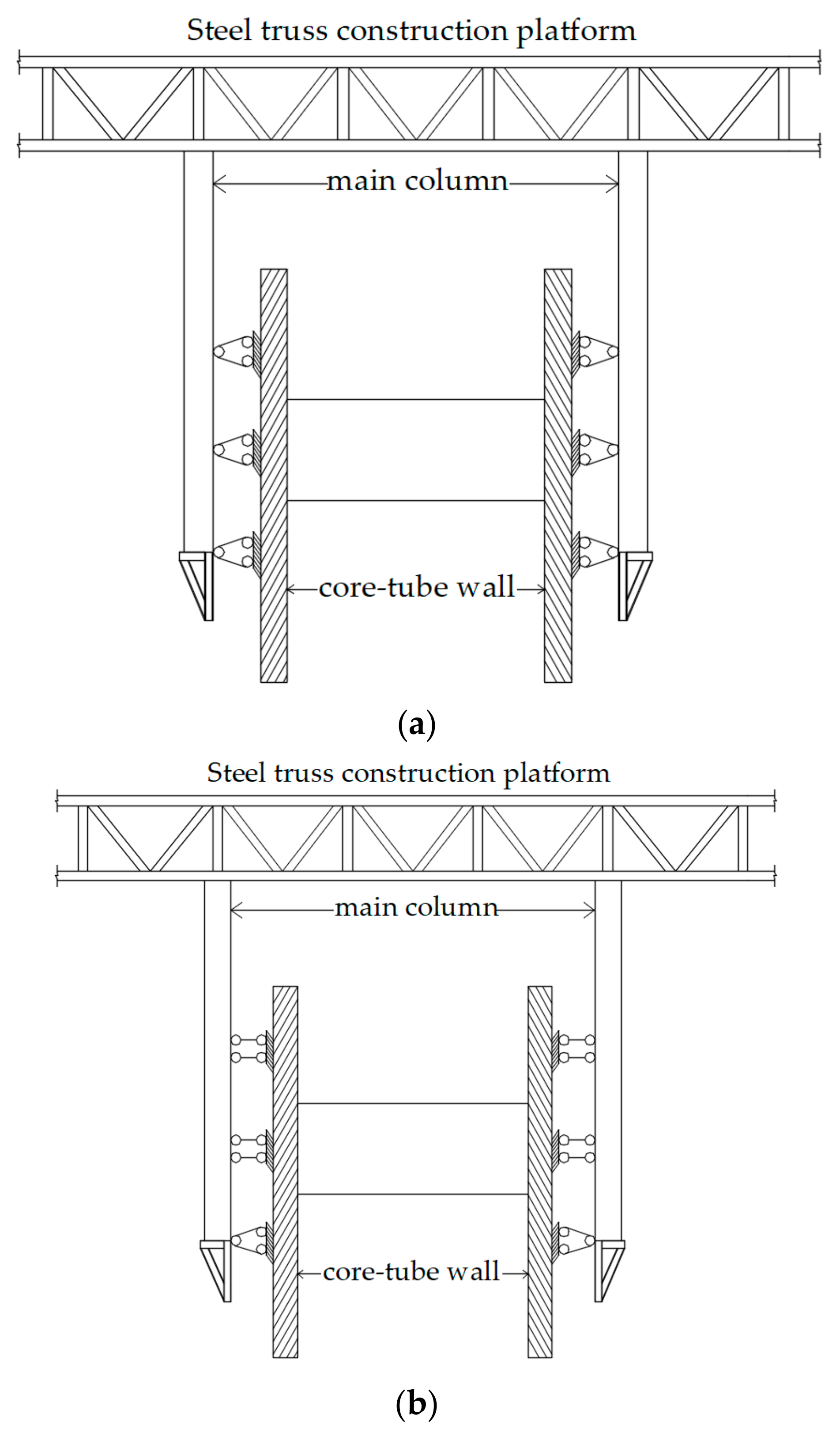
3. Jacking Steel Truss and Main Column Design

3.1. Component Selection

The specific cross-sectional dimensions of each member are shown in Table 1.

3.2. Design of Steel Truss

The core tube steel truss platform of this project is a 1.8 m high truss. In order to facilitate the hoisting construction of the components, the distribution of trusses should allow enough space between them, and 500 mm of space is also reserved for the corresponding parts of the core tube wall and the outer frame to remove and clean up the formwork. Considering the requirements of platform loading and deformation, the steel truss platform is supported on five main columns. The specific connection form of the truss is shown in Figure 2. At the same time, the steel truss is attached to the formwork, hanger, construction machinery (two cloth machines), and materials, which must have sufficient strength and stiffness.
The truss is a unit welded by structural steel and then a composite frame connected by a pin shaft and a special connector, on top of which a working platform is built. The wall column template is hung on the truss, and the hook with the roller can move in a direction perpendicular to the wall. After the concrete wall is poured and the formwork is removed, the wall bolts can be removed, the formwork is removed from the wall surface for a certain distance, and the formwork surface is cleaned. The hydraulic telescopic column lifts the overall frame to the next level. Workers can tie steel bars on the top working platform as the height increases. All the wall molds and inner and outer hangers on the truss also rise synchronously with the truss system.
The chords and webs of the primary and secondary trusses adopt the national standard for H-shaped steel (Q355B). The load of the steel platform mainly includes self-weight, constant load, and construction load. These loads are transmitted to the supporting main column through the main and secondary trusses, then transmitted to the attached wall seat by the supporting main column, and finally borne by the structural wall.

3.3. Main Column Design

The main column includes the retractable column and the outer vertical truss column. The vertical truss column is connected to the top truss platform, and the outer tube of the telescopic column is connected to the vertical truss column, as shown in Figure 3.
The telescopic column is composed of an external tube and an internal tube. It is equipped with a hydraulic cylinder, and it has a hydraulic oil source, a control valve, and an electronic control system. In the design, the hydraulic cylinder is used to top the vertical load, and the square tube is used to overcome the lateral load. The vertical truss column is hung on the wall through the guide rail wall seat. The guide rail on the vertical truss column and the guide wheel on the attached wall support form an anti-tilt device to resist lateral load and wind load.
The core tube of this project is rectangular. To improve the loading capacity and enhance the stability of the formwork, five fulcrum main columns and five main columns are used to support the truss platform. When the main column is arranged, it is necessary to ensure a safe distance between the standard section of the tower crane and the steel truss and reserve sufficient space for the swing of the tower crane. At the same time, the necessary safe distance should be reserved for the tower crane seat beam and the construction platform support beam to meet the requirements of the tower crane seat beam turnover. The position of the leg on the wall and the truss must avoid the steel column and the hidden column in the wall. When that is impossible, it is necessary to consider avoiding the steel bar on the hidden column.

4. Numerical Simulation

Midas Gen software (South Korea) was used to establish the finite element model of the jacking steel truss, analyze the stress under different working conditions, and comprehensively evaluate the safety of the steel truss to ensure the safe and smooth operation of the jacking steel truss.

4.1. Setting of Boundary Conditions

The jacking steel truss can be divided into the construction stage, jacking stage, and lifting stage. The calculation model was established according to the actual support situation, and the boundary constraints of each model are shown in Figure 4.
(1)
The construction stage
The connection between the lower chord of the main truss and the top end of the attached support column is rigid, and the ends of the upper and lower support frames are set as hinge supports that constrain the movement of XYZ in three directions. As shown in Figure 4a.
(2)
The jacking stage
When jacked up, the end of the lower support frame was set to restrict the hinge support moving in the three directions of XYZ, the wall-attached guide rail of the upper support frame was set to restrict the sliding support moving in the XY direction, and the hydraulic cylinder lifted the upper support frame to the set height, as shown in Figure 4b.
(3)
Lifting stage
When lifting, the upper support frame was the main bearing member, and its end was set as a hinge support that restricted the movement of XYZ in three directions. The hydraulic cylinder lifted the lower support frame to the reserved hole to complete the lifting operation, as shown in Figure 4c.

4.2. Load Value

The values of constant load and live load are listed in Table 2 and Table 3, respectively.

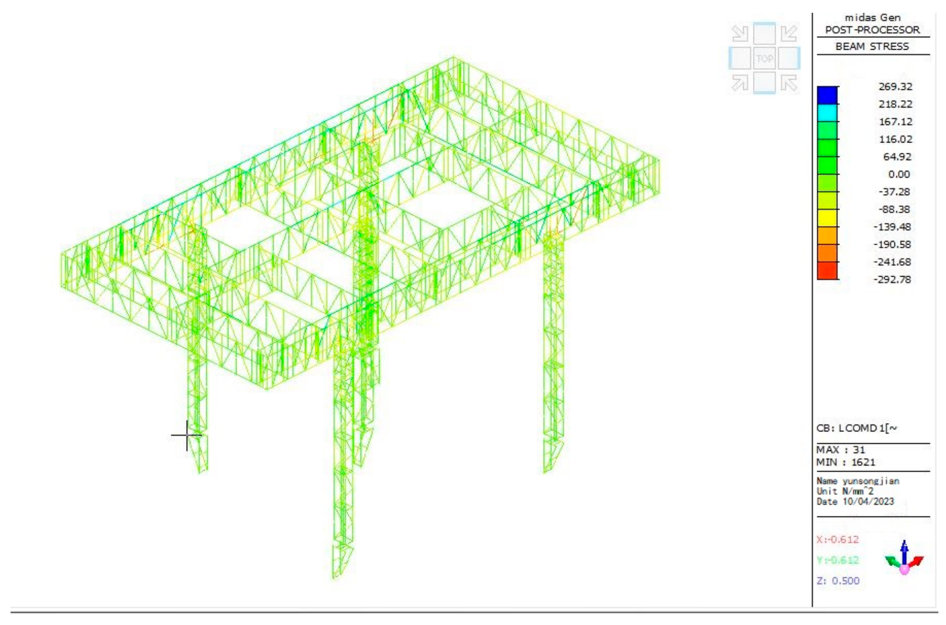
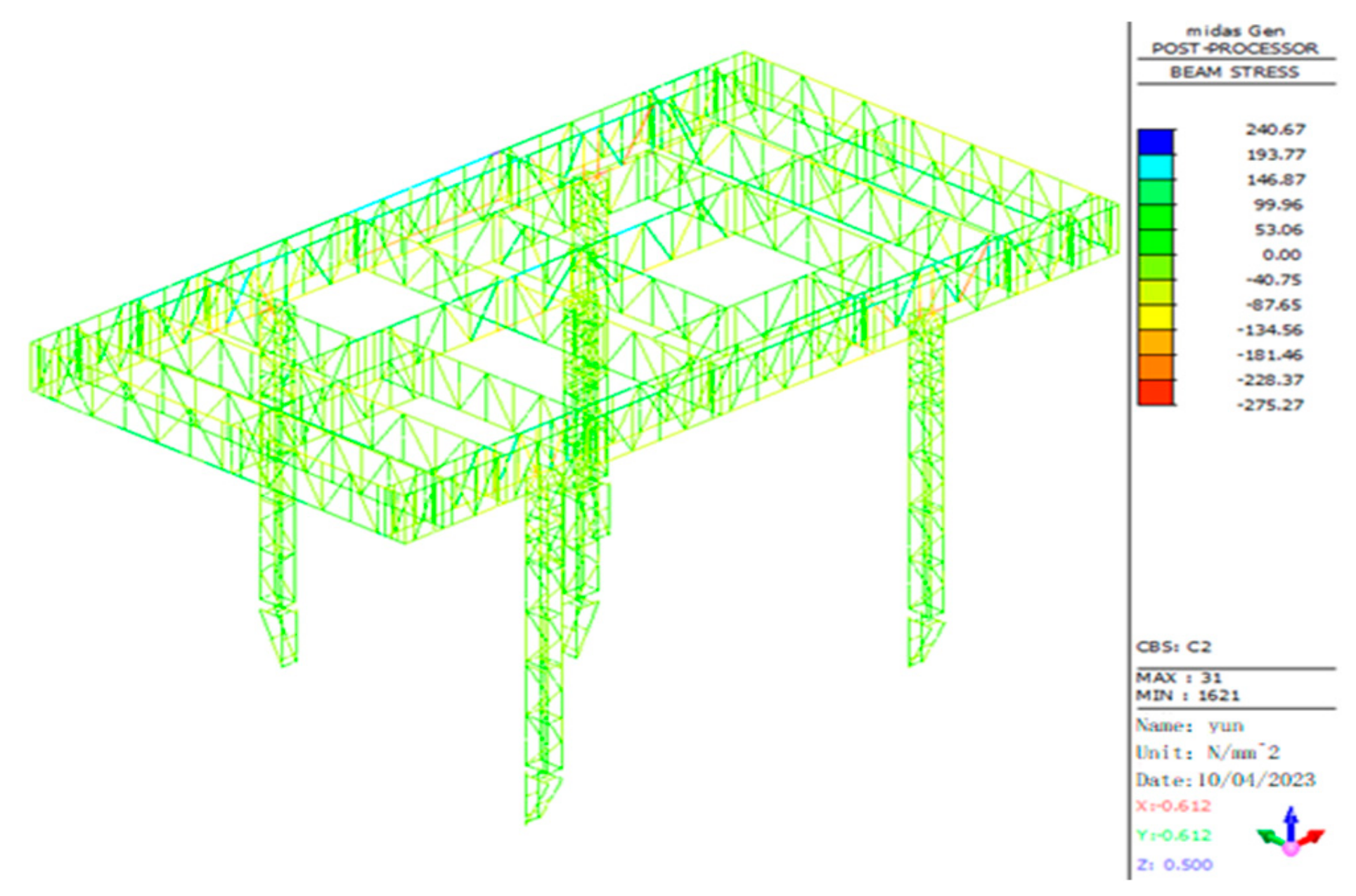
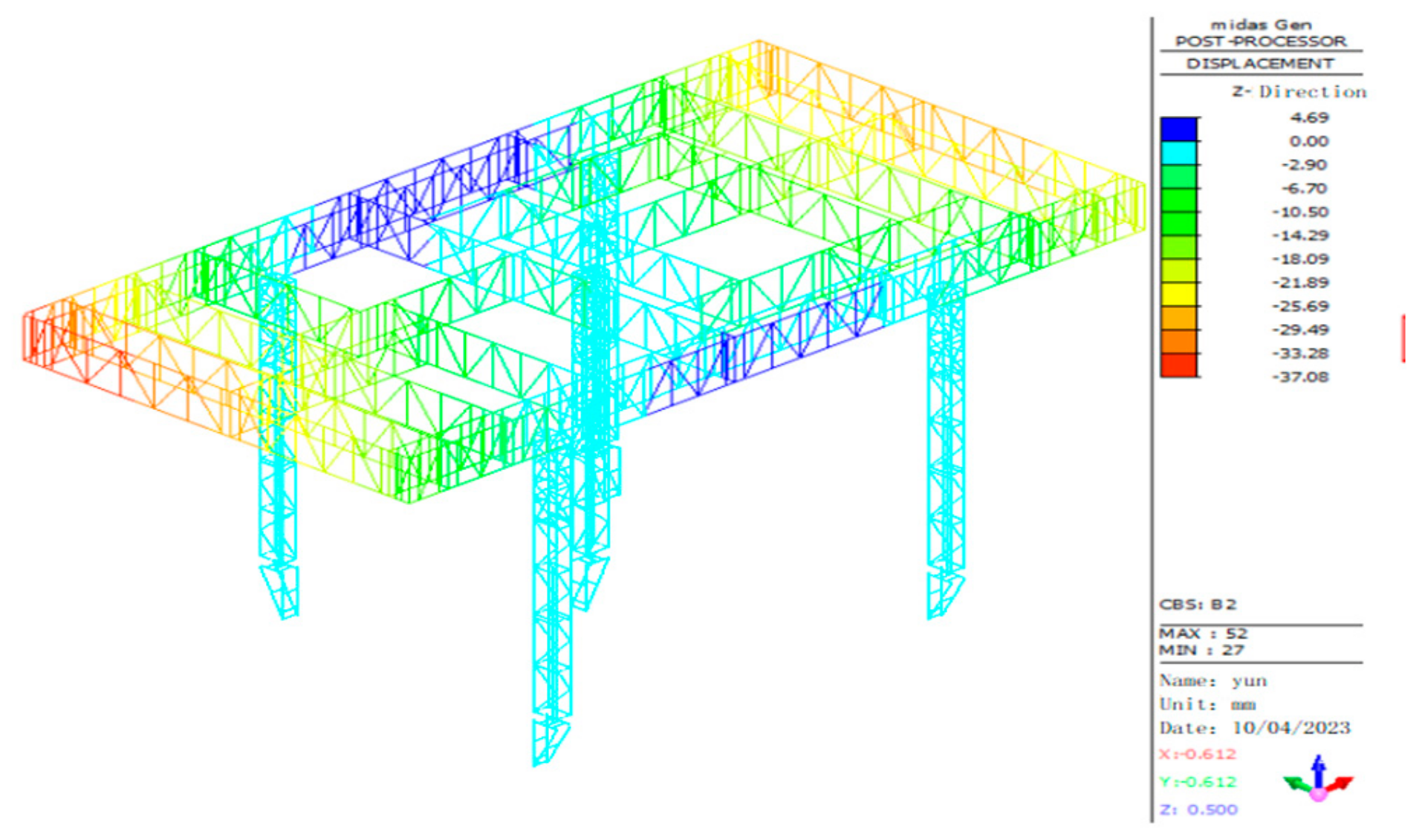
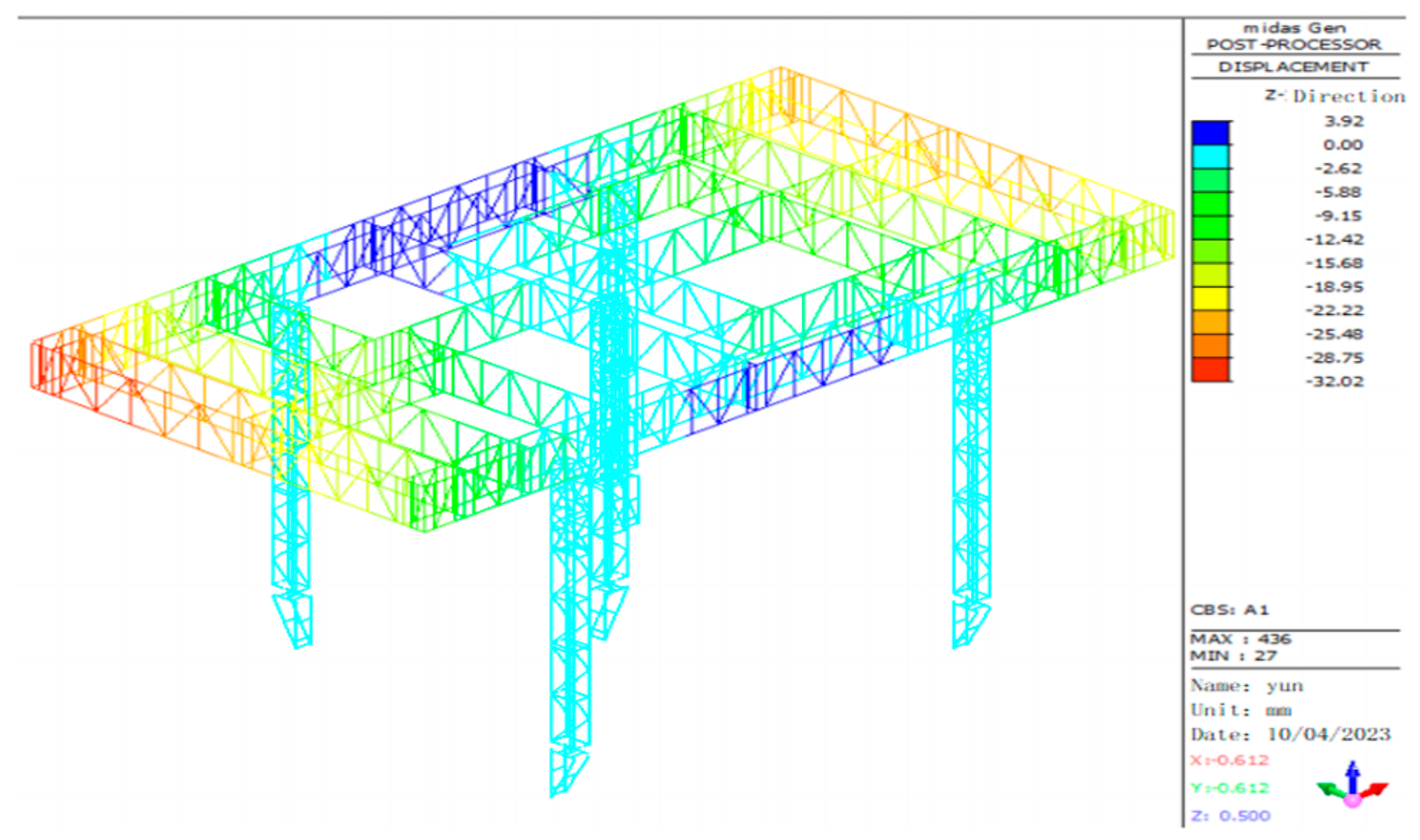
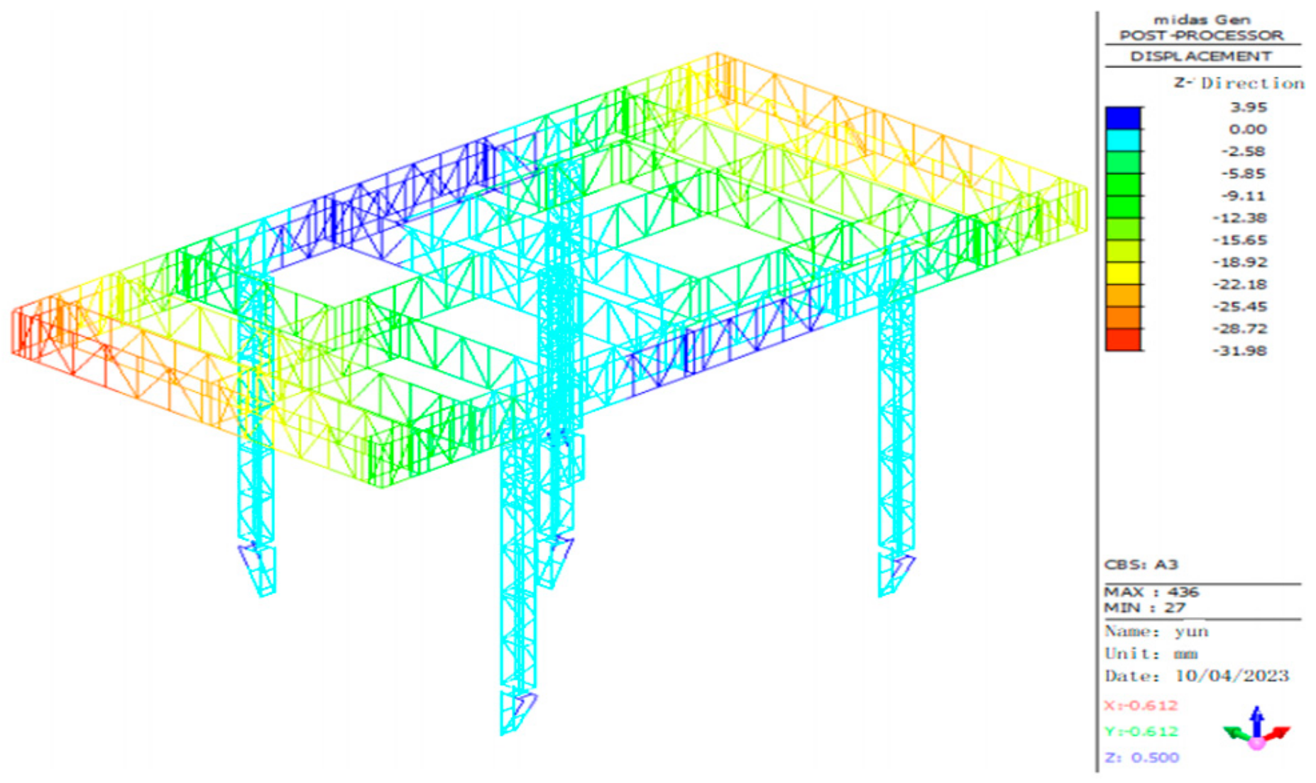
4.3. Finite Element Simulation

Midas Gen was used for the finite element modeling, and the calculation models of the construction stage, jacking stage, and lifting stage under different working conditions were established. After analysis and calculation, three stress cloud diagrams were created. A stress cloud diagram under the construction stage is shown in Figure 5, a stress cloud diagram under the jacking stage is shown in Figure 6, and a stress cloud diagram under the lifting stage is shown in Figure 7.
According to the stress cloud diagrams, in the construction stage, the stress value near the connection point between the main column and the main truss oblique web rod on the northeast side was the largest, reaching 292.78 N/mm2; in the jacking stage, the stress value near the connection point between the main column and the main truss oblique web member on the northeast side was the largest, reaching 275.27 N/mm2; in the lifting stage, the stress value near the connection point between the main column and the main truss oblique web member on the northeast side was the largest, reaching 151.90 N/mm2.
According to the stress cloud diagrams, in the construction stage, the vertical displacement of the upper chord, lower chord, and web member of the steel truss at the northwest corner of the steel truss construction platform was the largest, and the maximum vertical displacement was 37.08 mm, as shown in Figure 8. In the jacking stage, the vertical displacement of the upper chord, lower chord, and web member of the steel truss at the northwest corner of the steel truss construction platform was the largest, and the maximum vertical displacement was 32.02 mm, as shown in Figure 9. In the lifting stage, the vertical displacement of the upper chord, lower chord, and web member of the steel truss at the northwest corner of the steel truss construction platform was the largest, and the maximum vertical displacement was 31.98 mm, as shown in Figure 10.

4.4. Linear Buckling Analysis

Through linear buckling analysis, it is easy to determine the buckling coefficient and buckling mode of the structure, and the obtained modal results can provide a reference for nonlinear analysis. The ultimate bearing capacity and instability failure mode of the structure can be approximately obtained by the buckling analysis, and the equilibrium equation is shown in Formula (1).
K E + λ K G U = λ P
In the formula:
  • KE—Elastic stiffness matrix of structure;
  • KG—Geometric stiffness matrix of the structure;
  • {U}—Nodal displacement;
  • {P}—Nodal load;
  • λ—Eigenvalue.
Through the calculation and analysis of the previous section, it can be seen that the stress and displacement of the jacking steel truss were the largest in the construction stage. Therefore, the construction stage was selected for loading in this buckling analysis. The ultimate bearing capacity of the jacking steel truss was 13,820.92 kN, and its buckling eigenvalues under the first- to sixth-order buckling modes are shown in Table 4. The finite element analysis results of the lowest-order buckling mode are shown in Figure 11.
It can be seen from Figure 11 that the minimum first-order eigenvalue of the jack-up steel platform was 5.105, indicating that the critical load of the first-order instability mode reached five times that of the applied load. Therefore, the steel platform has a certain stability reserve as a whole, and the north-side truss is most likely to be unstable. When the buckling characteristic value increases, the unstable form of the structure changes from local instability to overall instability.

5. Field Monitoring

5.1. Steel Truss Monitoring Instruments and Measuring Point Arrangement

(1)
Layout of stress monitoring points
The steel truss platform was the main load-bearing skeleton in the construction process. The upper part of the platform had a heaped load and a construction load. The lower part of the platform was suspended with the formwork and hanger, and there was a construction load on the hanger at the same time. Therefore, it was important to monitor the stress and strain of the key parts of the steel truss platform structure throughout the construction period.
The stress-monitoring instrument selected to monitor the components of the key parts was the YL-VWS vibrating wire surface strain gauge. The strain gauges were mainly arranged in the upper and lower chords and oblique web members of the support beam of the main column wall-attached support. There were 14 stress and strain measuring points for all structural monitoring, as shown in Figure 12. The in the figure indicates the location of the strain gauges.
(2)
Introduction of monitoring instruments
The YL-VWS vibrating wire strain gauge is suitable for long-term burial in hydraulic structures or other concrete structures, as shown in Figure 13. It can measure the strain inside the structure and the temperature of the burial point simultaneously. Measurement range: X axis, Y axis; resolution: 0.005°; precision: 0.01°; measurement range: ±10°; operating temperature range: −20~65 °C. The field test diagram is shown in Figure 14.

5.2. Main Pillar Monitoring Instruments and Measuring Point Arrangement

(1)
Wireless inclinometer monitoring point layout
The verticality monitoring of the main support column is an important part of this project. It runs through the construction safety of the jacking formwork system structure and can be used to evaluate the overall safety of the structure. In this project, a YL-IMG (W) wireless inclinometer was used to monitor the verticality of the main column structure. The purpose of verticality monitoring is to monitor the two-way inclination of the main column during the jacking process of the formwork.
For inclination monitoring, a precision inclinometer was set at the top of the vertical support column of the jacked steel truss. Each inclinometer can monitor the bidirectional inclination angle, for a total of five inclinometers. The data can be uploaded to the online monitoring system, which integrates intelligent collection, storage, transmission, and management, all of which can be automatically collected. There were five main columns in the jacking formwork system of this project, and the inclinometer was installed at the top of each supporting column.
(2)
Introduction of monitoring instruments
This monitoring project used the Shanghai Yanlian wireless inclinometer YL-IMG (W) for verticality monitoring, as shown in Figure 15. The IMG has a biaxial inclination test function, which can monitor the instability of the jacking rod and the inclination of the support system. It is used for attitude monitoring. It also has excellent temperature stability. It can maintain high measurement accuracy in a temperature environment of −20–65 °C and is more suitable for long-term field monitoring. It can continuously operate for 144 h with a standby time of 13 days. In addition, the measurement accuracy of the system can reach 0.01°, so that the tilt and pitch angles of the sensor output relative to the horizontal plane can be measured. The field monitoring map is shown in Figure 16.

5.3. Data Monitoring and Analysis

(1)
Stress monitoring of steel truss
When the monitoring instrument was installed, the jacking steel truss and the main column were assembled and constructed for 10 floors. Thus, in the normal construction of the jacking formwork system, the stress measured by the strain gauge was not the total strain of each measuring point of the jacking formwork but the strain generated at each measuring point under several main loads, such as live load, machine material, and wind load.
During the construction of the jacking formwork, the acquisition box was kept in an energized state. Data acquisition was set to perform every hour. The data will be stored in the system for a long time, and data acquisition will be performed manually regularly. This paper displays the stress change diagram of some measuring points in Figure 17.
The monitoring data analysis used the data collected in the 2023/8/30–2023/9/30 stage. ZHJ-1 represents the lower flange of the upper chord (ZHJ-1-1), the upper flange of the lower chord (ZHJ-1-3), and the lower flange of the oblique web member (ZHJ-1-2) of the supporting beam of the No. 1 main column wall-attached support. ZHJ-2 represents the lower flange of the upper chord (ZHJ-2-1), the upper flange of the lower chord (ZHJ-2-3), and the lower flange of the oblique web member (ZHJ-2-2) of the supporting beam of the No. 2 main column wall-attached support. ZHJ-4 represents the lower flange of the upper chord (ZHJ-4-1), the upper flange of the lower chord (ZHJ-4-3), and the lower flange of the diagonal web member (ZHJ-4-2) of the support beam of the wall-attached support of the No. 4 main column. ZHJ-5 represents the lower flange of the upper chord (ZHJ-5-1), the upper flange of the lower chord (ZHJ-5-3), and the lower flange of the diagonal web member (ZHJ-5-2) of the support beam of the wall-attached support of the No. 5 main column. CHJ-1 represents the upper flange of the lower chord of the northwest corner of the cantilever section of the steel truss; CHJ-2 represents the upper flange of the lower chord of the southeast corner of the steel truss cantilever section.
It can be seen from Figure 17a that the tension was the largest during the construction stage, and the maximum compressive stress value was 123.06 N/mm2. In the initial stage of jacking, the compressive stress value reached 49.82 N/mm2; the stress change trend of the measuring point ZHJ-1-2 under the three operation stages is shown in Figure 17b. The peak value of the compressive stress appeared in the construction stage, and the maximum compressive stress value was 117.41 N/mm2. The stress change trend of ZHJ-1-3 in the three operation stages is shown in Figure 17c. The peak value of compressive stress appeared in the construction stage, and the maximum compressive stress value was 164.25 N/mm2. The stress gradually decreased in the lifting stage, and the minimum compressive stress value was 29.72 N/mm2. The stress variation trend of the measuring point CHJ-1 under the three operating stages is shown in Figure 17d. The peak value of the compressive stress appeared in the construction stage, and the maximum compressive stress value was 139.66 N/mm2.
According to the analysis of the monitoring results, it was concluded that in the jacking stage, when the cylinder jacks up the support column, the instantaneous impact force was generated on the structure. Therefore, the component was located at the position where the support column was connected with the truss, so it produced stress changes during the jacking period. In the construction stage, the construction live load was large, the vibration was generated when pouring concrete, and the damper could be considered in the later stage. In the lifting stage, the stress changes were more frequent and accompanied by sudden changes. This is due to the need to continuously adjust the attached wall support to install it during the lifting. Due to the high sensitivity of the strain gauge, the stress change curve experienced a sudden change.
(2)
Main pillar verticality monitoring
To reduce the impact on the jacking, the wireless two-axis inclinometer was installed on the truss below the jacking cylinder of the five main pillars. The X direction was the long-side direction of the steel truss. Figure 18 and Figure 19 show the changes in the inclination angles of the five main columns in the X direction and Y direction during the construction stage.
During the monitoring period, the maximum inclination angle of the main column was 0.15°, which was the X direction of the No. 2 column. The main reason is that a distributing machine was arranged near the No. 2 column. The distributing machine was installed above the steel truss, and the vibration was generated when pouring concrete, which disturbed the main column.
According to the change curve of each main column, it can be seen that under different working conditions, the inclination of the main column changed irregularly, and the cumulative change angle was small, indicating that the project would not have a significant impact on the main column in the jacking and lifting stages. The main reason for the sudden change in the inclination angle was that the inclinometer was hit or the load above the steel truss experienced a sudden change. This indicates that more attention should be paid to the load distribution in the construction stage to improve the safety and stability of the climbing formwork structure.

5.4. Comparative Analysis of Monitoring Value and Simulation Value

The measured field values were compared with the finite element simulation values, and the specific results are shown in Table 5.
The simulated values of the measuring points in the three operation stages of jacking, construction, and lifting were always near the range of the measured values, and the change trend was also consistent with the simulated values. The peak value of stress at the measuring point during the construction stage was the same as that obtained from the field test, and the error between the measured maximum stress value and the simulated value was controlled within 10%. In general, the measured value was in good agreement with the simulated value.

6. Conclusions

Through the numerical simulation and monitoring of the stress of the jacking steel truss and the verticality of the main column of a super high-rise building in Xi’an, the following three conclusions are drawn:
(1)
The stress monitoring results of the jacking steel truss were compared with the simulated values. The monitoring results were consistent with the simulated values, and the error was kept within 10%. The reasons for the error analysis are that, when using the finite element software to model, the influence conditions are generally idealized, the on-site environment is complex and changeable, and the interference of construction and personnel cannot be ruled out. The vibrating wire strain gauge and the biaxial inclinometer have high sensitivity and are susceptible to the interference of the external environment. Therefore, the simulation process cannot completely track the mechanical properties of the actual structure.
(2)
The inclination angle of the No. 2 main column in the X direction was the largest, reaching 0.15°, which did not exceed the standard limit. In the later construction, it was necessary to strictly limit the loading at the cantilever end. During the jacking and lifting, the construction of the outer hanger should be stopped.
(3)
According to the monitoring results, the stress of the steel truss and the verticality of the main column were within the specified limits, and the jacking formwork system was stable, safe, and reliable.

Author Contributions

Conceptualization, H.G.; methodology, L.C. and H.G.; software, L.C.; validation, Z.Z.; resources, F.Z. and Z.Z.; writing—original draft preparation, L.C.; writing—review and editing, F.Z.; visualization, T.G.; project administration, F.Z and T.G. All authors have read and agreed to the published version of the manuscript.

Funding

This research received no external funding.

Data Availability Statement

The raw data supporting the conclusions of this article will be made available by the authors on request.

Conflicts of Interest

Authors Haiying Guo, Zhenyu Zhang and Teng Gao were employed by the company SCEGC No.1 Construction Engineering Group Company Ltd. The remaining authors declare that the research was conducted in the absence of any commercial or financial relationships that could be construed as a potential conflict of interest.

References

  1. Chen, W.; Wang, D.; Zhong, J.; Ding, N.; Liu, X.; Luo, J.; Wu, X.; Dai, D. Research and development of steel structure platform system of ground type air building machine. Build. Sci. 2022, 38, 174–179. [Google Scholar]
  2. Han, Y.; Shan, H.; Li, D.; Hu, Y.; Ao, X.; Liu, H.; Ren, Y.; Kong, S. Construction technology of intelligent jacking-up steel platform of dongguan world trade center T2 tower. Constr. Technol. 2019, 48, 71–75. [Google Scholar]
  3. Ke, Z.; Zhou, H.; Gao, B.; Xu, M.; Wen, P. Design and application of hanging steel formwork under integral lifting platform. Constr. Technol. 2017, 46, 38–42. [Google Scholar]
  4. Xin, W. Analysis of the Mechanical Characteristics and Optimal Design of a Jacking Steel Platform for a Super High-Rise Building. Master’s Thesis, Xi’an University of Architecture and Technology, Xi’an, China, 2022. [Google Scholar]
  5. Liu, X. Analysis and Construction Technology Research of Key Systems of Intelligent Construction Machine for Super High-Rise Buildings. Master’s Thesis, Xi’an Technological University, Xi’an, China, 2023. [Google Scholar]
  6. Ma, F. Study on Direct Analysis Method and Its Application Based on Second-Order Notional Load Method. Master’s Thesis, Lanzhou University, Lanzhou, China, 2022. [Google Scholar]
  7. Cao, C.; Yan, D.; Zhong, J.; Yang, K. Based on BIM technology of micro convex pivot jack-up construction formwork design intelligent control application integration innovation. Constr. Technol. 2016, 45, 772–775. [Google Scholar]
  8. Ceng, F.; Liu, X.; Pan, Z.; Xing, G.; Zhang, J.; Lu, X. Construction simulation and monitoring of a formwork for super high-rise building. Ind. Constr. 2021, 51, 127–131, 136. [Google Scholar]
  9. Yu, H. Comparative Analysis of Field Monitoring and Numerical Simulation for Jacking Formwork Steel Platform of Super High-Rise. Master’s Thesis, Xi’an Technological University, Xi’an, China, 2021. [Google Scholar]
  10. Zhang, Y.; Zhao, W.; Su, G.; Guo, Q.; Huang, S. Monitoring Technology for the Whole Construction Process of Integrated Tower Crane Top Formwork System in Hefei Hengda Center. Constr. Technol. 2019, 48, 135–138. [Google Scholar]
  11. Zhao, S. Design and Research of a Ground-Based Hydraulic Jacking Formwork System. Master’s Thesis, Xi’an University of Architecture and Technology, Xi’an, China, 2022. [Google Scholar]
  12. Chen, Z.; Zheng, H.; Li, F.; Meng, F.; Wang, Y.; Li, W.; Sai, H.; Qiu, F. Monitoring and analysis of the hydraulic self-climbing mold stability of super high-rise buildings. Constr. Technol. 2020, 49, 121–124, 128. [Google Scholar]
  13. Zhou, J.Z.; Liao, M.P.; Zhuang, J.P.; Lin, Q.; Cai, X.F. Site Measurement of Modularized Low-Position Hydraulic Jacking Formwork System. Appl. Mech. Mater. 2013, 405, 3108–3112. [Google Scholar] [CrossRef]
  14. Gao, F.; Zhou, H.; Liang, H.; Weng, S.; Zhu, H. Structural deformation monitoring and numerical simulation of a supertall building during construction stage. Eng. Struct. 2020, 209, 110033. [Google Scholar] [CrossRef]
  15. Zhong, X. Modular Design and Application of Jacking Formwork in Super High-Rise Core Tube. Master’s Thesis, Jiangsu University, Suzhou, China, 2016. [Google Scholar]
  16. Bai, X.; Ma, H.; Yao, C.; Bai, R. Design and modal analysis of jacking formwork system for super high-rise building. Ind. Constr. 2013, 43, 14–17, 51. [Google Scholar]
  17. Huang, T. Design and application of integral hydraulic climbing steel platform to high-rise building construction. Build. Constr. 2016, 38, 1254–1256, 1268. [Google Scholar]
Figure 1. Diagram of the core tube standard layer plane form.
Buildings 14 00617 g001
Figure 2. Schematic diagram of the steel truss.
Buildings 14 00617 g002
Figure 3. Diagram of the main column.
Buildings 14 00617 g003
Figure 4. Constraint diagram of each construction stage. (a) Construction stage; (b) jacking stage; (c) lifting stage.
Buildings 14 00617 g004aBuildings 14 00617 g004b
Figure 5. Stress cloud diagram of the construction stage.
Buildings 14 00617 g005
Figure 6. Stress cloud diagram of the jacking stage.
Buildings 14 00617 g006
Figure 7. Stress cloud diagram of the lifting stage.
Buildings 14 00617 g007
Figure 8. Displacement cloud diagram of the construction stage.
Buildings 14 00617 g008
Figure 9. Displacement cloud diagram of the jacking stage.
Buildings 14 00617 g009
Figure 10. Displacement cloud diagram of the lifting stage.
Buildings 14 00617 g010
Figure 11. The first-order buckling mode of the structure.
Buildings 14 00617 g011
Figure 12. Plane diagram of strain gauge measuring point.
Buildings 14 00617 g012
Figure 13. YL-VWS model vibrating wire strain gauge.
Buildings 14 00617 g013
Figure 14. Strain gauge field installation diagram.
Buildings 14 00617 g014
Figure 15. YL-IMG (W) wireless inclinometer.
Buildings 14 00617 g015
Figure 16. Field instrument layout.
Buildings 14 00617 g016
Figure 17. Stress variation diagram of the measuring points. (a) ZHJ-1-1 measuring point; (b) ZHJ-1-2 measuring point; (c) ZHJ-1-3 measuring point; (d) CHJ-1 measuring point.
Buildings 14 00617 g017aBuildings 14 00617 g017b
Figure 18. X-biased angle change figure.
Buildings 14 00617 g018
Figure 19. Y-biased angle change figure.
Buildings 14 00617 g019
Table 1. Jacking steel truss member section sizes.
MemberNameSectional Dimension
TrussUpper and lower chordHW300 mm × 300 mm × 10 mm × 15 mm
Oblique ventral rodHW150 mm × 150 mm × 7 mm × 10 mm
Vertical web memberHW300 mm × 150 mm × 6.5 mm × 9 mm
Connecting piece☐150 mm × 150 mm × 16 mm
Steel columnInner tube☐400 mm × 400 mm × 20 mm
Outer tube☐470 mm × 470 mm × 16 mm
Outrigger trussChord member☐300 mm × 150 mm × 15 mm
Web member☐150 mm × 150 mm × 15 mm
Table 2. Constant load.
Load NameLoad Values
Construction platformConstruction platform plate0.33 kN/m2
Internal protective fence0.12 kN/m2
External protective fence0.18 kN/m2
Fabric machine10 t
Construction platform support keelH-shaped steel0.28 kN/m
Channel steel0.15 kN/m
GallowsHanging beam0.28 kN/m
Outboard suspension4.6 kN/m
Inside hanger3.0 kN/m
Aluminum alloy formwork 1.2 kN/m
Table 3. Live load.
Table 3. Live load.
Load NameLoad Values
Walkway of crane beam1.55 kN/m2
Steel truss construction platform0.5 kN/m2
Loading of steel bar6.0 kN/m2
Table 4. Eigenvalues corresponding to first- to sixth-order buckling modes.
ModalityEigenvalue
15.105
28.099
310.151
410.456
511.096
611.819
Table 5. Summary of simulated and measured values.
Rod PartsRising StageConstruction StageLifting Cord Stage
Measured RangeValue of SimulationMeasured RangeValue of SimulationMeasured RangeValue of Simulation
ZHJ-1-10.55~65.8359.6277.81~123.06118.670.18~48.2850.61
ZHJ-1-2−45.05~−24.33−43.11−116.02~−96.32−114.9−44.50~−1.29−42.65
ZHJ-1-3−70.31~−59.11−69.17−165.04~−108.12−155.89−59.66~−30.97−56.82
CHJ-186.48~88.7492.56137.06~139.66145.26102.79~107.48102.84
Disclaimer/Publisher’s Note: The statements, opinions and data contained in all publications are solely those of the individual author(s) and contributor(s) and not of MDPI and/or the editor(s). MDPI and/or the editor(s) disclaim responsibility for any injury to people or property resulting from any ideas, methods, instructions or products referred to in the content.

