Article

Mechanical Properties and Loading Simulation of Unidirectional Laminated Slabs Made from Recycled Concrete with Manufactured Sand

1
School of Civil and Architectural Engineering, Changzhou Institute of Technology, Changzhou 213032, China
2
School of Urban Construction, Changzhou University, Changzhou 213164, China
*
Author to whom correspondence should be addressed.
Buildings 2024, 14(3), 674; https://doi.org/10.3390/buildings14030674
Submission received: 10 February 2024 / Revised: 27 February 2024 / Accepted: 29 February 2024 / Published: 3 March 2024
(This article belongs to the Section Building Materials, and Repair & Renovation)

Abstract

:
To align with the trend of the development of prefabricated buildings, this study aimed to produce unidirectional laminated slabs by using recycled concrete with manufactured sand (RCM). Additionally, performance evaluation and loading simulation analyses were conducted on these unidirectional laminated slabs. The experimental results indicate that the mechanical characteristics of RCM closely approximate those of recycled aggregate concrete (RAC), and they are all higher than the design value. Under ultimate loading conditions, the mid-span deflection of laminated slabs fabricated with RCM surpasses its RAC counterpart by 5.9%, indicating a pronounced proximity in flexural performance between RCM and RAC laminated slabs. Concurrently, ABAQUS finite element software was used to compare and simulate the performance of the unidirectional laminated slabs. The difference between the deflection generated by the actual applied ultimate load and the deflection generated by the simulated ultimate load is about 7.1%, and the simulation results are very close to the experimental results. Based on the experimental results, the practical application of RCM unidirectional laminated slabs has high value in the field of construction engineering.

1. Introduction

Prefabricated buildings have become a significant construction method in the contemporary construction industry due to their significant contributions to energy efficiency and emission reduction, continuously developing technology, and higher building standards [1,2,3,4]. The core of prefabricated building lies in the assembly of prefabricated components using mechanical equipment, which offers high production efficiency and environmental friendliness [5]. The construction industry is currently facing a very severe issue, namely, the excessive exploitation of natural resources, leading to price increases for various construction raw materials, and a decreasing annual usage of some materials. In this context, the utilization of green and sustainable raw materials in the construction industry becomes particularly important [6]. Common green building materials nowadays include recycled aggregate concrete (RAC), manufactured sand (MS), and similar components [7,8]. The continuous promotion and utilization of these raw materials offer new possibilities for sustainable development in the construction industry.
Nowadays, combining green and environmentally friendly materials such as RAC with prefabricated buildings has become a research hotspot, and many researchers have already undertaken related work. Lu et al. [9] investigated the flexural performance of composite panels by combining RAC with normal weight concrete and steel plates, achieving good synergy despite the significant sliding of the panels. In another study, Tian et al. [10] conducted vertical static loading tests on continuous-span concrete composite panels, utilizing beam and slab connections joined by screw bolts and perforated folded plates. Their research results indicate that the bending performance of these panels is least sensitive to concrete strength and shear bond thickness. Fayed et al. [11] tested solid/hollow aluminum tube (AT) columns filled with sea sand recycled aggregate concrete (SRAC) until compression. The study was conducted on circular and square specimens. The results showed that the recycled concrete aggregate content slightly affected the mechanical properties of SRAC and had illegible influence on the behavior of SRAC-filled ATs. Moreover, Zhang et al. [12] observed that the interfacial bonding characteristics of steel-RAC composite panels depend on the height of the steel bridge deck ribs. Although RAC has some applications in the field of prefabricated buildings, the research on the applications of RCM is still relatively limited.
Finite element software can be used to establish basic models of various concrete structures or composite structures. By inputting the basic properties of materials, cross-sectional characteristics, interactions, and constraints between various components, combination conditions of structures and loads and boundary conditions of model assemblies, the established model can be analyzed and calculated. Finally, by analyzing the stress situation and results, as well as the failure scenarios of various components under varying loads, we can realistically simulate the engineering application status of these structural components. This enables us to verify the feasibility of large-scale engineering projects. This is similar to the work of many researchers [13,14,15].
RAC is a new type of building material that conforms to the principles of sustainability, characterized by the widespread use of recycled aggregates in the production process [16,17]. These aggregates come from discarded concrete and other construction waste, to some extent replacing the natural aggregates used in traditional concrete products [18]. The promotion and application of RAC not only change the source of construction raw materials but also address issues such as material shortages and the accumulation and disposal of construction waste, significantly reducing the environmental burden of the construction industry [19,20]. Although RAC may exhibit some differences in performance attributes, such as strength and durability, when compared to traditional concrete, a lot of research and innovative methods have generated numerous ways to enhance the overall performance of RAC [21,22,23], such as the physical and chemical methods of modified aggregates, the addition of various pozzolan materials, biological methods, the addition of steel fibers, other types of fibers, and other methods [24,25,26,27]. These methods provide important theoretical support for practical engineering applications for RAC.
In the current context, China is gradually prohibiting the extraction of river sand in certain river sections as part of its efforts to establish a new national development model and implement a sustainable development strategy [28,29]. The extraction of river sand is a significant issue, not only in the realm of construction raw materials but also in the political, economic, and environmental domains [30]. MS is an engineered aggregate that undergoes fine processing using specialized grinding equipment and can be custom-produced to meet specific requirements. MS typically exhibits a rough surface texture characterized by numerous angular edges [31,32]. The existing research primarily suggests that MS’s irregular shape, its serrated surface, and angular geometry contribute to enhancing the bond between cementitious materials and aggregates, thereby improving the fundamental properties of concrete [33,34,35]. The relationship between compressive strength and the addition of MS and RAC is non-linear [36,37]. Although MS has some performance deficiencies compared to river sand, it still complies with the Chinese standards GB/T 14684-2022 [38].
This study aims to combine MS with recycled concrete and apply it to prefabricated components. By comparing RCM with RAC, this experiment assesses the fundamental performance of both concretes. The deflection changes and crack propagation forms in unidirectional laminated slabs under loads were studied, and the characteristic loads during the construction and use stages of unidirectional laminated slabs were determined and compared with other similar studies [39,40,41,42]. Additionally, load–deflection curves are established and compared with similar experiments [43,44,45]. Furthermore, ABAQUS finite element software is employed to simulate and analyze the load tests of these slabs, yielding conclusions consistent with the experimental results. Through software simulation, the actual load conditions of unidirectional laminated slabs were effectively replicated, and the correlation between the real operational state of these slabs and the simulated load scenarios were established. The combination of experimental and simulation results provides theoretical support for the application of RCM in prefabricated buildings.

2. Materials and Methods
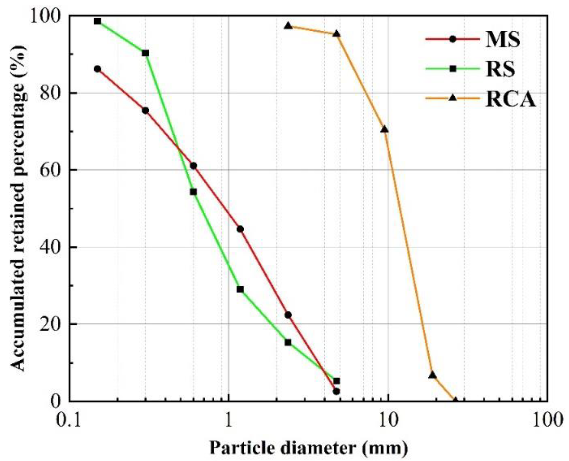
2.1. Materials

The primary cementitious materials employed in this study were ordinary Portland cement (P·O 42.5) sourced from Jiangsu Jinfeng Cement Group and fly ash from Changzhou Hutang Thermal Power Plant (Changzhou, China); the chemical composition of the two is shown in Table 1. The fly ash exhibited an apparent density of 2550 kg/m3 and a specific surface area of 470 m2/kg, characteristics conducive to the desired improvements in concrete properties. The recycled coarse aggregate used in the experiment was produced by Jiangsu Lvhe Environmental Technology Co., Ltd. (Changzhou, China), while natural sand and machine-made sand were produced by Changzhou China Railway Urban Construction Component Co., Ltd. (Changzhou, China). The water reducer used in this experiment was a high-performance polycarboxylate water reducer specially designed for manufactured sand provided by Jiangsu Nigao Technology Co., Ltd. (Changzhou, China), with a water reduction efficiency of about 30%. In this study, recycled coarse aggregates (RCAs) characterized by a particle size ranging from 5 to 20 mm were employed, and the detailed parameters of coarse and fine aggregates are shown in Table 2. The grading curves of various aggregates are shown in Figure 1 (all parameters were obtained according to the calculation method provided by the Chinese standard GB/T 14684-2022 [38] and GB/T 25177-2010 [46]).

2.2. The Mix Proportion of Recycled Concrete

The water-cementitious ratio (W/C) for the concrete mixture is set to 0.48 and 0.42, with a slump parameter of 150 mm ± 30 mm being employed. Mix proportion design is based on the method provided by Chen et al. [47]. In the process of producing the concrete mixture, due to the elevated water absorption attributes of the manufactured sand and recycled coarse aggregate, it is necessary to supplement water during the concrete preparation stage. The specific details pertaining to the composition ratios are presented in Table 3.

2.3. Design of Samples and Laminated Slabs

The concrete mixing process employed the secondary blending technique [48], the details of which are given in Figure 2. After vibration, the prepared concrete samples were added into the respective molds, with dimensions predetermined for both samples and layered panels. Upon demolding, each specimen underwent curing in accordance with established standard protocols. The stipulated standard curing regimen involved temperature maintenance at 20 ± 5 °C, with humidity levels mandated to remain above 95%.

2.3.1. Size of Sample Molds

The dimensions of the samples were 100 mm × 100 mm × 100 mm for the compressive strength and splitting tensile strength, while the axial compressive strength test samples had dimensions of 300 mm × 150 mm × 150 mm.

2.3.2. Materials and Dimensions of Laminated Slabs

The specific parameters of the four laminated slabs, fabricated from RAC and RCM, are presented in Table 4. The table delineates the composition and dimensional configurations of the laminated slabs.

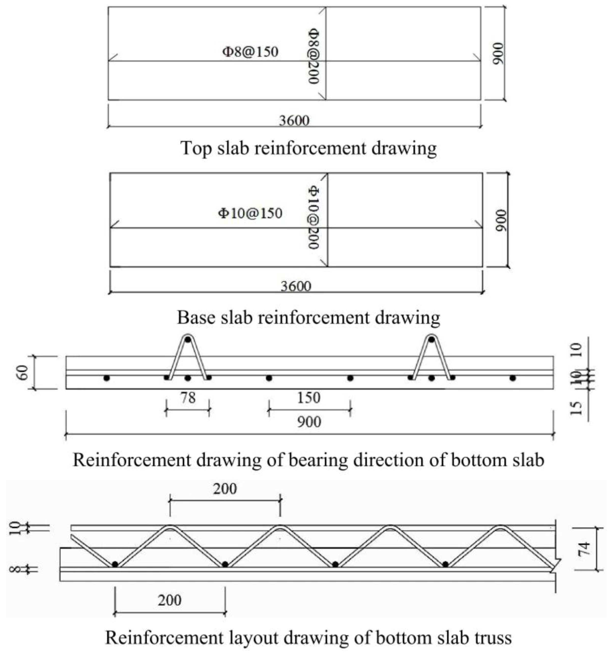
2.3.3. Arrangement of Reinforcement

The laminated base slab featured a reinforcement diameter of Φ10 HRB400, while the post-cast segment incorporated Φ8 HRB400 reinforcement. The truss reinforcement, positioned at a distance of 225 mm from the side, consisted of D74 reinforcement, with the precise arrangement of reinforcements depicted in Figure 3.

2.4. Test Methods for Recycled Concrete

2.4.1. Mechanical Property Test

The compressive strength, splitting tensile strength, and axial compressive strength of the recycled concrete were assessed in accordance with the guidelines outlined in the Chinese Standard GB/T 50081-2019 [49].

2.4.2. SEM Test

The microscopic morphology of the recycled concrete was examined through the utilization of scanning electron microscopy (SEM). The test pieces comprised the section without any treatment. Before the test, the sample was sprayed with gold to improve the conductivity of the concrete sample.

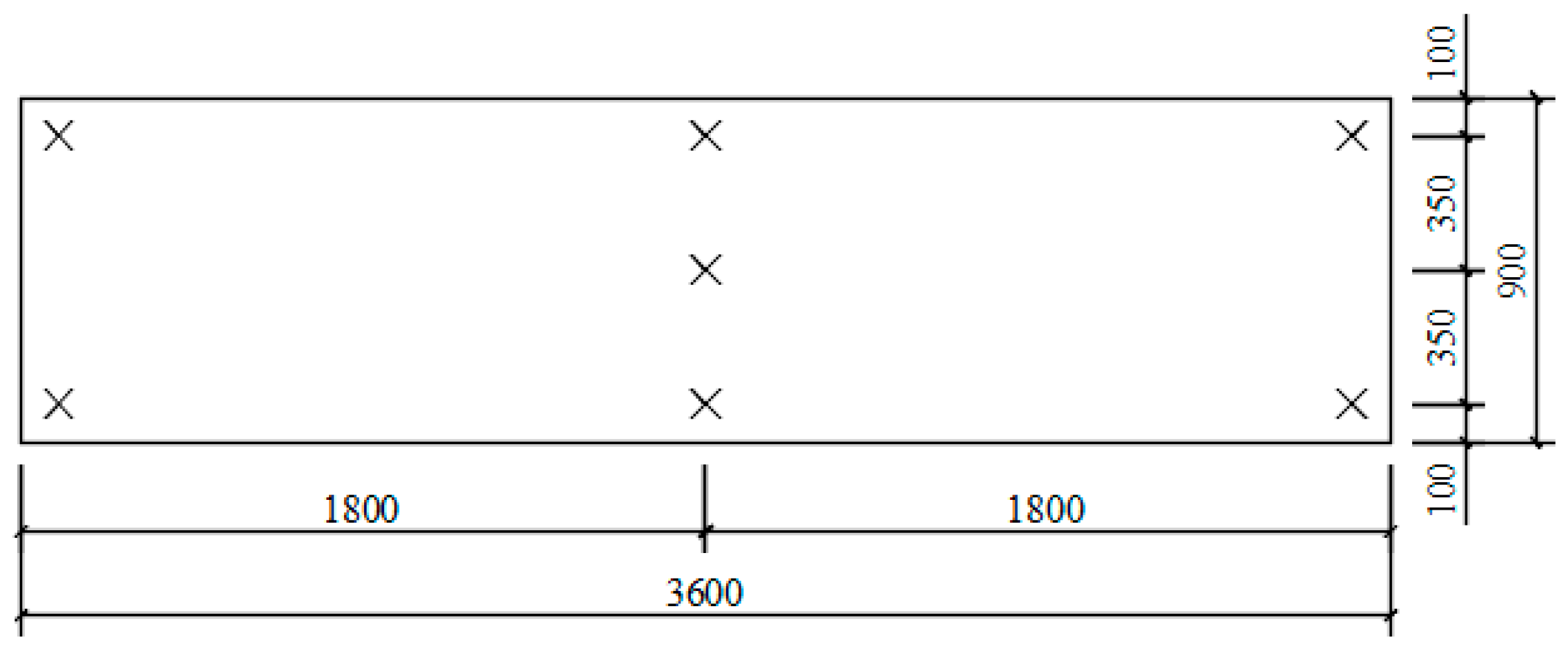
2.5. Arrangement of Measuring Points

2.5.1. Measuring Point of Reinforcement Strain Gauge

The placement of reinforcement strain gauges is warranted at locations prone to crack initiation. Given the elevated stress concentrations at the mid-span of the laminated slabs, the emergence of cracks is commonly observed in this region. As a result, three strain gauges should be affixed equidistantly along the central axis of the trio of load-bearing reinforcements positioned at the underside of the mid-span slab. The precise locations for the attachment of the reinforcement strain gauges are illustrated in Figure 4. Subsequent data collection for the reinforcement strain was performed, employing the static strain testing apparatus available within the laboratory setting.

2.5.2. Measuring Point of the Displacement Meter

A total of seven measuring points were strategically positioned for each slab to facilitate comprehensive measurements. Among these, three displacement meter measuring points were allocated along the mid-span of the lower surface of the experimental laminated slabs, specifically, at both lateral extremities and at the mid-point of the mid-span slab. Additionally, two displacement meter measuring points were situated at the supports to effectively regulate the mid-span deflection. The spatial distribution of the displacement meter measuring points across the laminated slab can be observed in Figure 5.

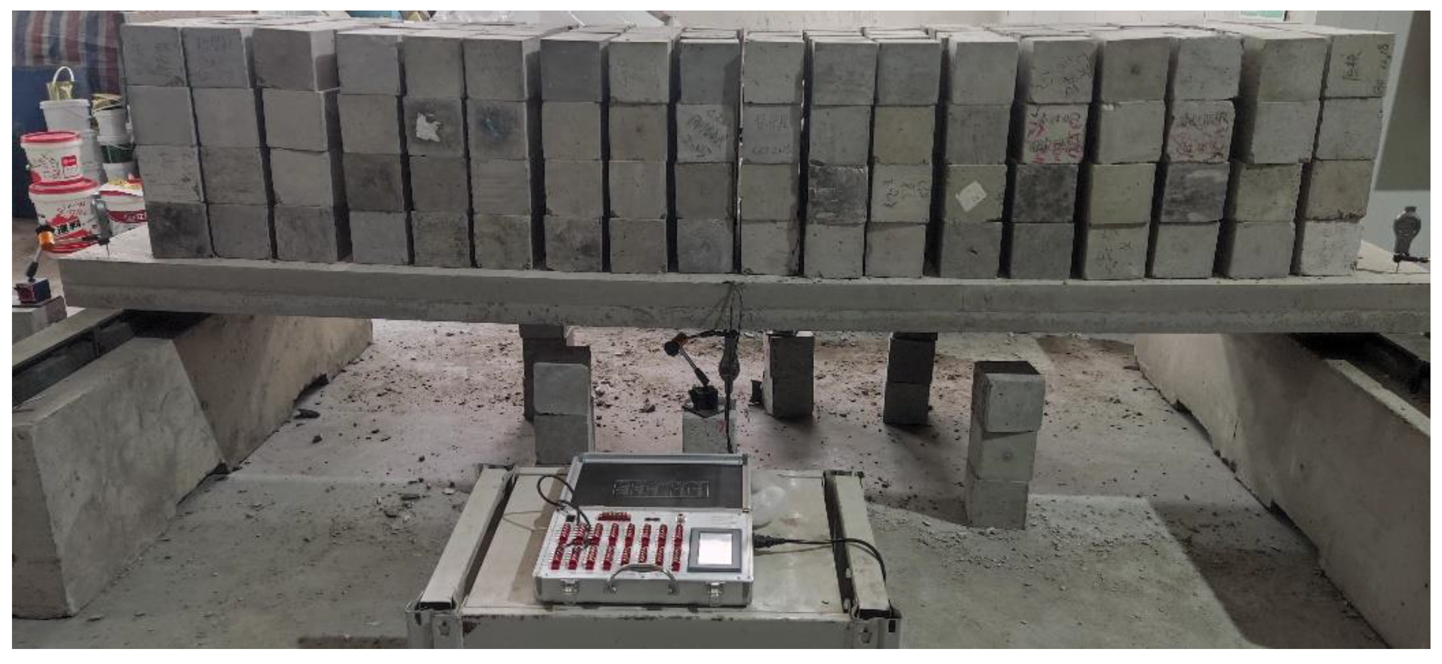
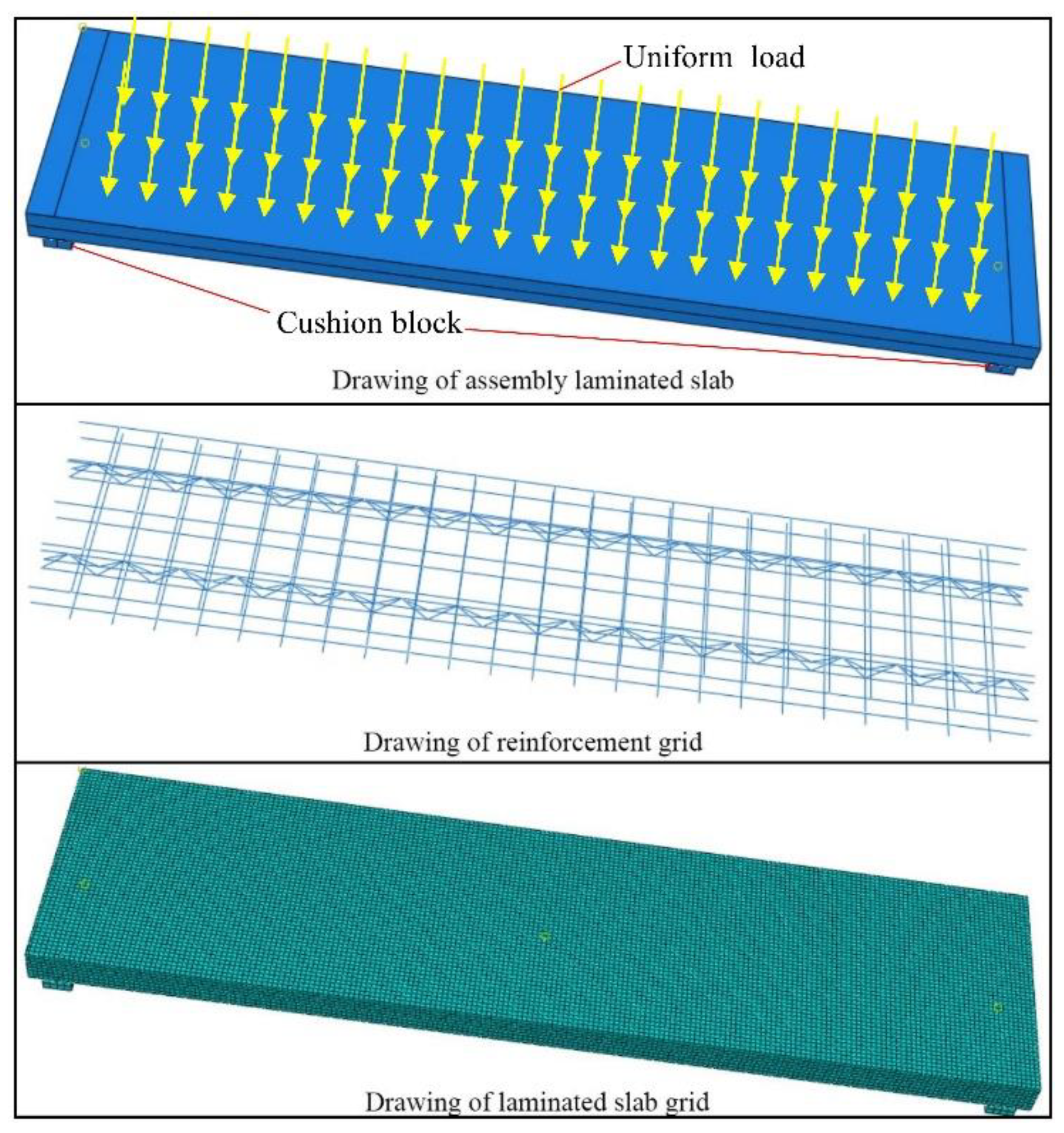
2.6. Loading Scheme of Laminated Slabs

In adherence to the Chinese standards GB 50204-2015 and GB 50010-2010 [50,51], the deflection threshold for the bending slab is stipulated as 1/200 of the span length, serving as the basis for computing the slab’s span within the context of serviceability limit states. The present experiment intends to consider the loading process of laminated base slabs as the post-construction operational state; the process of loading laminated slabs is regarded as the normal usage state of prefabricated buildings. The determination of the cracking load and ultimate load of the slab is predicated upon the following conditions.
Laminated slab loading is achieved through the utilization of uniformly distributed surface loads, employing a progressive loading methodology.
Loading scheme for two individual single slabs: in the first stage, an incremental load of 0.47 kN/m2 is applied and sustained for 10 min, reaching an aggregate load of 2.35 kN/m2. Subsequently, the second stage involves the application of a stepwise load of 0.235 kN/m2, maintained for 10 min, culminating in a cumulative load of 3.76 kN/m2.
Loading scheme for two laminated slabs: in the first stage, an incremental load of 0.94 kN/m2 is applied and sustained for 10 min, reaching an aggregate load of 8.46 kN/m2. Subsequently, the second stage involves the application of a stepwise load of 0.47 kN/m2, maintained for 10 min, culminating in a cumulative load of 15.51 kN/m2. The actual loading test is shown in Figure 6.
Cracking load: when, under a certain level of load, cracks appear at the bottom of the slab, the cracking load is the previous one. If cracks appear at the bottom of the plate during the load stability period, then the cracking load is half of the sum of the previous value and this value.
The cracking load in this article refers to the load level at which cracks first appear at the bottom of the slab. If cracks emerge during the load stability period, the cracking load is calculated as half of the sum of the previous load value and the current load value.
Ultimate load: (1) large deformation (deflection reaches 1/50 of the calculated span); (2) the crack width reaches 1.5 mm, or the reinforcement strain reaches 0.01; (3) the tensile main reinforcement suddenly breaks; (4) the concrete in the pressure area is crushed under pressure.
In order to ensure the safety of the testing process, it is mandated that the testing procedure be promptly ceased, and the applied load be removed when the mid-span deflection of the laminated base slab nears a threshold equivalent to 1/50 of the calculated span of the slab during the loading assessment. The state of the crack at the bottom of the slab is photographed at the same time. Within the ambit of laminated slab testing, the evaluative parameter for ascertaining the loading limit state of the laminated slab is predicated upon the selection of the maximal crack aperture, measured at 1.5 mm. Concurrently, a meticulous observation is conducted to discern the potential presence of lateral cracks manifesting on the surface of the laminated slab, as well as to detect any instances of slip along its laminated interface.

2.7. ABAQUS Modeling of Laminated Slabs

2.7.1. Property of Concrete and Reinforcement in ABAQUS

The experimental investigation entailed the utilization of ABAQUS software (The software version is ABAQUS/CAE 2021) to conduct a comprehensive simulation and analysis of the RCM laminated slab. A pivotal parameter under scrutiny was the elastic modulus of RCM1 and RAC1. This parameter is calculated using the formula introduced by Xiao [52], as shown below:
E c r = 5.5 × 10 3 × f c r × ρ r 2400 × 1 r 2.2876 × r + 0.1288 , R = 0.99
where Ecr (Gpa) is the elastic modulus of recycled concrete, fcr (Mpa) is the prism compressive strength of recycled concrete, ρr (kg/m3) is the apparent density of recycled concrete, and r (%) is the replacement rate of recycled coarse aggregate.
In modeling, the bottom bearing was set as a rigid cushion block (without deformation under load) and connected to the concrete laminated slab. ‘Tie’ connection was adopted, which means that the cushion block was bound to the laminated slab, and then the boundary condition was set as a hinge at the bottom of the cushion block. The concrete adopted the continuous solid element C3D8R, which can accurately simulate the characteristics of small pieces of material. The reinforcement used space truss element T3D2, which did not consider the bond slip between the reinforcement and the concrete. The reinforcement skeleton was embedded into the concrete using the ‘Embedded region’ function. The cohesive force friction mixed model was selected in the finite element analysis, and the interaction properties of the two slabs were defined by corresponding parameters. The specific size data of each component were consistent with the actual experiment. The assembly laminated slab is shown in Figure 7.

2.7.2. Analysis Step Setting and Grid Generation

The laminated slab, reinforcement, and cushion block shall have meshed. The size of the concrete grid was about 18 mm, the reinforcement grid was about 10 mm, and the cushion block grid was about 15 mm. The division grid is shown in Figure 8.

2.7.3. Submit Analysis Job and Post Processing

After the ABAQUS software completes the part creation, material and section definition, assembly definition, analysis step setting, load and boundary condition definition, and grid generation, the pre-processing work is completed. The finite element analysis and calculation of the model are carried out using the ‘Job’ module in the software.
After the model analysis is completed, the ‘Visualization’ module can be used for post processing. It can draw X-Y curves, display cloud diagrams, display deformation diagrams, and analyze the results more intuitively.

3. Test Results

3.1. Physical Properties of Test Samples

3.1.1. Strength of Samples

The outcomes of strength tests are graphically depicted in Figure 8. At the 28 d, both RAC and RCM achieved compressive strengths approximately ranging from 100% to 120% of the stipulated design strength. Comparing the splitting tensile strength and axial compressive strength of RCM1 and RCM2 samples with those of the corresponding RAC samples, it is observed that the former exhibited marginally lower values. Based on some existing studies [16,17,18], this may be attributed to the fact that the particle size distribution of the MS used in this experiment differs from that of natural sand, resulting in a slight disadvantage in terms of strength. This disparity can be considered within the margin of error, reflecting that the performance of RCM is nearly indistinguishable from that of RAC.

3.1.2. SEM Analysis

As depicted in Figure 9, the microstructural examination reveals significant insights into the curing progression. Following a 3 d curing period, both RCM and RAC display analogous microstructural features. These encompass an augmented presence of unreacted cementitious particles, an increased incidence of reticular ettringite (Calcium sulphoaluminate hydrate, aFt), and a heightened prevalence of voids within the mortar matrix. However, the samples subjected to a 7 d curing regimen are marked by the emergence of numerous small crystalline clusters composed of calcium silicate hydrate (C-S-H). Concurrently, traces of calcium hydroxide (CH) are also discernible in the 7 d samples, indicating the continuation of the ongoing hydration reactions. Concurrently, it is evident that the interfacial transition zone (ITZ) in the samples of RAC exhibits a more uniform pattern, accompanied by a denser structure of hydration products. Upon reaching the 28 d curing regimen, a more pronounced change is the substantial observation of abundant C-S-H gel within the mortar. This contrasts with the 7 d samples, wherein the C-S-H gel appears as discrete particles, whereas at 28 days, it assumes a more cohesive and interconnected morphology. In RCM samples, the irregular distribution of hydration products remains evident, and there are some unreacted fly ash particles present. This could be a contributing factor to the slightly diminished performance of RCM. However, on the whole, the microscopic morphologies of both materials bear a close resemblance.

3.2. Loading Results and Analysis of Laminated Slabs

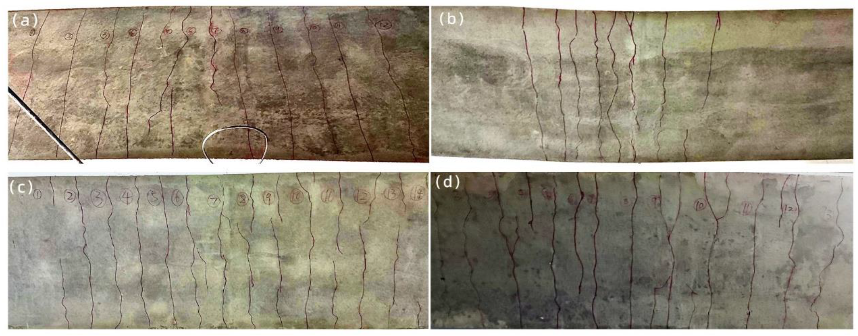
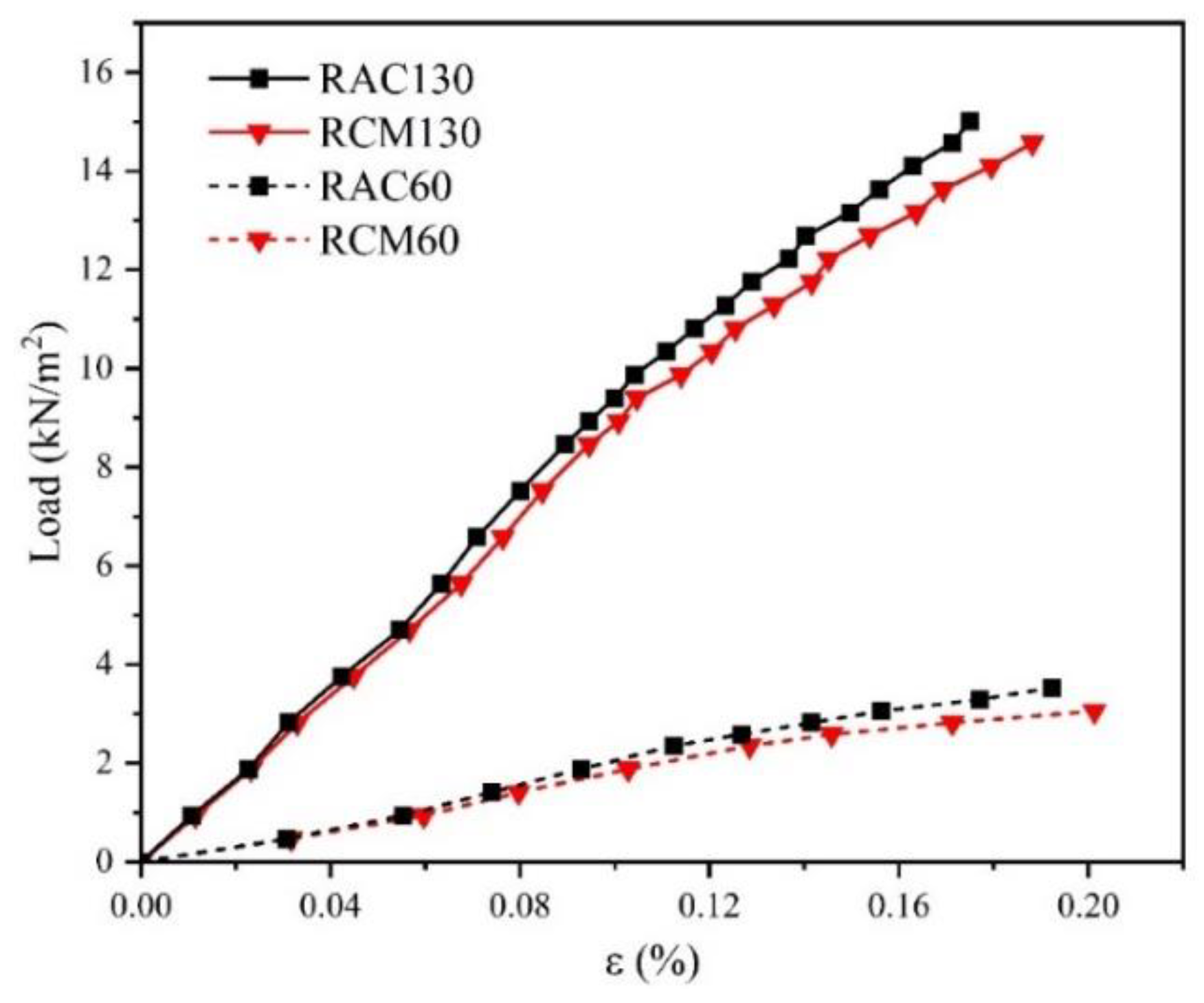
3.2.1. Loading Results for Laminated Slabs

The loading progression of the concrete laminated slab can be delineated into three distinct phases: the elastic phase, the elastic–plastic phase, and the damage phase. During the loading process of the laminated slabs, no slip was found at the laminated surface throughout the entire process, so this article does not consider the issue of bond slip between the laminated slabs The various data during the loading process of the laminated board are shown in Table 5.
Figure 10 illustrates the post-loading crack patterns exhibited by each slab. During the initial phase of the actual loading process, the laminated slab exhibited a discernible deflection, albeit devoid of visible cracks. This phase corresponded to the elastic stage. As loading progressed, the undersurface of the slabs gradually developed cracks, signifying the transition to the elastic–plastic stage. During this juncture, the cracking load of the RCM60 laminated base slab was approximately 20.1% lower than that of RAC60, while RCM130 exhibited a reduction of about 6.1% compared to RAC130; some phenomena in the experiment were similar to those in the existing research [39,40,41,42]. The incorporation of manufactured sand admixture accelerated the initiation of cracking, as indicated by this divergence. As demonstrated in the preceding discussion, there was no significant disparity in fundamental performance between RCM and RAC. This outcome can be attributed to the relatively weaker bond between RCM and steel reinforcement, an aspect that will be examined in the forthcoming chapters. Concurrently, as the crack width and quantity evolved, the deflection of the laminated slab steadily increased, yet structural damage remained incipient. Subsequently, upon the attainment of the ultimate load for the concrete slab, a point was reached where either the deflection or crack width exceeded the designated serviceability limit state. This marked the advent of the damage stage. This is similar to the three stages of concrete slab loading found in the experiments by Mostakhdemin Hosseini et al. [43]: the service stage, yield stage, and maximum load. At this juncture, the ultimate load of the RCM60 laminated base slab demonstrated a diminution of 18.6% compared to RAC60, whereas the RAC130 laminated slab exhibited a reduction of approximately 5.9% in comparison to its RAC130 counterpart. Evidently, the addition of manufactured sand has accelerated the damage inside the laminated slab to a certain extent. Nonetheless, this influence has a limited impact on the ultimate damage observed in the 130 mm laminated slab configuration.

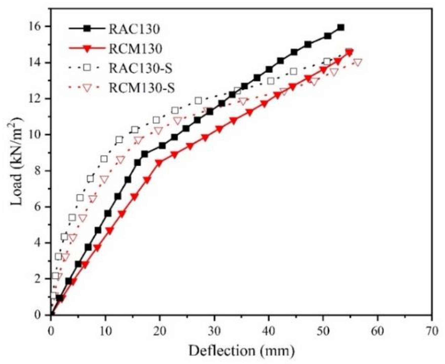
3.2.2. Relationship between Mid-Span Load and Deflection

In Figure 11, the load–deflection curves for RCM60 and RAC60 exhibit an inflection point at the onset of cracking load, with the profiles in the pre- and post-inflection stages displaying near-linear characteristics. The rate of deflection increase at the mid-span of RCM60 is greater than that for RAC60. The mid-span deflection of RCM60 reaches 1/200 of the calculated span (17 mm) at a load of 1.41 kN/m2. Upon surpassing a deflection of 60 mm, the load for RCM exceeds 2.82 kN/m2, whereas for RAC60, it reaches 3.53 kN/m2. Evidently, the performance of RCM laminated base slabs is inferior to that of RAC. Similarly, within the same graph, it can be observed that the load–deflection curves for the RCM130 and RAC130 laminated slabs exhibit a distinct inflection point. Before this inflection point, the increase in load is accompanied by a relatively modest rise in deflection. However, beyond this point, deflection rapidly escalates with increasing load, yet as the ultimate load capacity is approached, the load for RAC130 exceeds 15.95 kN/m2, whereas for RCM130, it is reduced by approximately 5.9%, reaching 15.01 kN/m2. The ultimate measurements reveal that the deflection of the RCM laminated slab is not significantly greater than that of the RAC laminated slab, and the associated results are in compliance with regulatory standards.

3.2.3. Stress–Strain Relationship of Reinforcement

The stress–strain correlation pertaining to reinforcement is depicted in Figure 12. A discernible observation entails the gradual augmentation in reinforcement strain congruent with escalating load increments. Preceding the initiation of concrete fissuring, both the laminated base slabs and laminated slabs exhibit an essentially linear relationship between load and strain. When the laminated slabs and laminated base slabs reach the deteriorative phase, it becomes clear that the reinforcement has not yet reached its yield point. This shows that the structural failure of the slab dose not depend on the performance of the steel reinforcement.

3.3. Simulation Results and Post-Processing

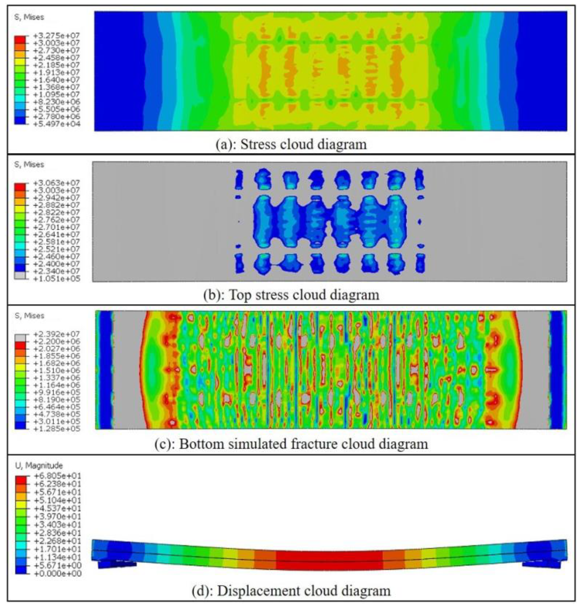
3.3.1. Loading Simulation Results for Laminated Slabs

The formulated model was subjected to computational analysis employing the Job module, which resulted in the successful convergence of the analytical model. The stress distribution contour map and displacement distribution contour map of the RCM130 laminated slab were derived, as illustrated in Figure 13.
In the elastic stage, the simulated deflection is slightly smaller than the test value, the bearing capacity is basically consistent, and the obtained load mid-span deflection curve is basically linear; this is consistent with the RCM laminated slabs. When the laminated slab enters the elastic–plastic stage, the simulated value for load mid-span deflection rises rapidly, and the simulated deflection value after a specific value is greater than the test value. In the damage stage, the increase rate of deflection becomes larger, and failure occurs when the deflection reaches 68 mm. Finally, it is determined that the simulation value of the ultimate load of the RCM laminated slab is 14.05 kN/m2 (the test value is 15.01 kN/m2). This is extremely close to the actual loading experimental values.
At the final damage stage, it can be seen from the top stress cloud Figure 13b (The blue–green area represents stress greater than 23.4 MPa) that the stress in some areas of the concrete has reached the compressive strength, so the top concrete has produced partial compressive damage, while the internal reinforcement is far from reaching the compressive strength or tensile strength, so the yielding of the reinforcement is not considered. At the mid span of the bottom slab, the stress in some areas has exceeded 2.2 MPa, resulting in tensile damage to the concrete. This can be observed in Figure 13c, where the gray area indicates a stress level higher than 2.2 MPa.

3.3.2. Post Processing of Laminated Slabs

Figure 14 shows the simulated load–deflection curves of the laminated slabs (RAC130-S and RCM130-S), with an average correlation coefficient (R2) exceeding 0.88 compared to the experimental results. From the comparison between the simulation and the actual tests, it can be seen that the deflection growth in the early stage is slow compared with the actual loading, and the loading curve has a similar shape and shows an approximately linear relationship. After the deflection reaches 1/200 of the calculated span (17 mm), the deflection increases steeply and rapidly, similar to the actual loading curve, and the simulated deflection increases more rapidly and soon exceeds the actual loading. The simulated deflection value of RCM130 is 7.1% higher than that of RAC130 under the ultimate load condition, which is similar to the actual loading condition. This is similar to the conclusion drawn by Hossain et al. [44] that finite element software can effectively simulate the structural performance of various types of laminated plates, and can predict parameters such as the load deflection response, ultimate/peak load, peak displacement, etc., in practical design applications. It can be observed that the differences in the inherent properties of RAC and RCM concrete have a similar impact on both practical experiments and simulations. While the use of MS leads to a decrease in performance, it does not significantly influence the overall load-carrying trend of the laminated slabs. Moreover, its effects remain limited, resulting in laminated slabs that meet regulatory requirements and can be employed in practical construction applications.

4. Conclusions

This study encompassed a comprehensive investigation of RCM, with a focus on examining a series of properties of RCM unidirectional laminated slabs. Furthermore, a comparative assessment between RCM and RAC laminated slabs was carried out to identify performance differences, and the performance of the RCM laminated slab was thoroughly analyzed using ABAQUS software. The main conclusions are summarized below.
  • In accordance with the findings of the conducted tests, both RAC and RCM achieved compressive strengths approximately ranging from 100% to 120% of the stipulated design strength. The performance of RCM test samples, produced through the substitution of natural sand with manufactured sand, demonstrates full compliance with the prescribed criteria. Therefore, RCM can completely replace RAC.
  • The SEM analysis results indicate that, at different curing stages, the hydration level of RAC samples is slightly higher than that of RCM samples. Moreover, the arrangement of the C-S-H gel formed during hydration is more uniform in RAC samples. However, there are no significant differences observed in the microscopic structure between RAC and RCM samples.
  • The results derived from the load testing of structural components reveal that the laminated slab comprised of RAC exhibits a good performance under typical operational conditions. Both the laminated base slabs and the laminated slabs exhibit similar actual loading progression; the cracking load of the RCM130 laminated slab is only 5.9% lower than that of RAC130, showing a very similar performance.
  • The simulation results indicate that RAC unidirectional laminated slabs and RCM unidirectional laminated slabs exhibit similar behavior under actual load conditions. The difference between the deflection generated by the actual applied ultimate load and the deflection generated by the simulated ultimate load is about 7.1%, indicating that the simulation can reflect the actual loading situation very well.

5. Future Work

Considering safety concerns, in this experiment, the recycled concrete unidirectional laminated slabs were only loaded until their ultimate deflection. In the future, further research will be conducted on various situations of unidirectional laminates loaded to fracture, such as maximum deflection, ultimate load, and sliding on the surface of the laminates.

Author Contributions

Conceptualization, X.W.; Methodology, K.H.; Formal analysis, F.W.; Investigation, T.Z.; Writing—original draft, F.W.; Project administration, X.W.; Funding acquisition, F.W. All authors have read and agreed to the published version of the manuscript.

Funding

This research was funded by the Postgraduate Research and Practice Innovation Program of Jiangsu Province (KYCX23_3096).

Data Availability Statement

The data presented in this study are available on request from the corresponding author. The data are not publicly available due to [privacy issues].

Conflicts of Interest

The authors declare that they have no known competing financial interests or personal relationships that could have appeared to influence the work reported in this paper.

References

  1. Liu, S.; Li, Z.; Teng, Y.; Dai, L. A dynamic simulation study on the sustainability of prefabricated buildings. Sustain. Cities Soc. 2022, 77, 103551. [Google Scholar] [CrossRef]
  2. Li, X.; Xie, W.; Yang, T.; Lin, C.; Jim, C. Carbon emission evaluation of prefabricated concrete composite plates during the building materialization stage. Build. Environ. 2023, 232, 110045. [Google Scholar] [CrossRef]
  3. Ferdous, W.; Bai, Y.; Ngo, T.D.; Manalo, A.; Mendis, P. New advancements, challenges and opportunities of multi-storey modular buildings—A state-of-the-art review. Eng. Struct. 2019, 183, 883–893. [Google Scholar] [CrossRef]
  4. Zhou, J.Y.; Li, Y.H.; Ren, D.D. Quantitative study on external benefits of prefabricated buildings: From perspectives of economy, environment, and society. Sustain. Cities Soc. 2022, 86, 104132. [Google Scholar] [CrossRef]
  5. Song, Y.; Wang, J.; Lu, J.; Si, X. Research on collaborative scheduling of multiple projects of prefabricated building based on the niche genetic-raccoon family optimization algorithm. Alex. Eng. J. 2023, 64, 1015–1033. [Google Scholar] [CrossRef]
  6. Zaragoza-Benzal, A.; Ferrández, D.; Atanes-Sánchez, E.; Morón, C. New lightened plaster material with dissolved recycled expanded polystyrene and end-of-life tyres fibres for building prefabricated industry. Case Stud. Constr. Mater. 2023, 18, e02178. [Google Scholar] [CrossRef]
  7. Ma, X.C.; Luo, W.J.; Yin, J. Review and feasibility analysis of prefabricated recycled concrete structure. IOP Conf. Ser. Earth Environ. Sci. 2020, 531, 012052. [Google Scholar] [CrossRef]
  8. Jian, S.M.; Wu, B.; Hu, N. Environmental impacts of three waste concrete recycling strategies for prefabricated components through comparative life cycle assessment. J. Clean. Prod. 2021, 328, 129463. [Google Scholar] [CrossRef]
  9. Lu, L.; Gao, M.; Guo, Y.; Wang, W.; Yan, H.; Jiang, T. Experiments on flexural behavior of the prefabricated RAC and NWC composite slab. Ain Shams Eng. J. 2022, 13, 101789. [Google Scholar] [CrossRef]
  10. Tian, J.; Wang, M.; Liu, J.; Guo, H.; Wang, Z.; Zhang, J. Experimental and numerical study of continuous span concrete composite slabs. Structures 2021, 34, 827–839. [Google Scholar] [CrossRef]
  11. Fayed, S.; Mansour, W. Structural performance of seasand recycled aggregate concrete filled Solid/ Hollow aluminum tubular Columns: An experimental work. Structures 2023, 47, 1323–1340. [Google Scholar] [CrossRef]
  12. Zhang, H.; Geng, Y.; Wang, Y.-Y.; Li, X.-Z. Experimental study and prediction model for bond behaviour of steel-recycled aggregate concrete composite slabs. J. Build. Eng. 2022, 53, 104585. [Google Scholar] [CrossRef]
  13. Wu, T.; Wang, G.; Wang, J.; Wang, Y.; Xu, R. Variational principles of laminated plates considering interlayer slip. Compos. Struct. 2022, 281, 114937. [Google Scholar] [CrossRef]
  14. Chen, S.; Shi, X. Shear bond mechanism of composite slabs—A universal FE approach. J. Constr. Steel Res. 2011, 67, 1475–1484. [Google Scholar] [CrossRef]
  15. Li, D.H.; Zhu, Z.J. Three-dimensional decoupled modeling on curing simulation of composite laminated plates with damage. Mater. Today Commun. 2022, 33, 104255. [Google Scholar] [CrossRef]
  16. Kim, J. Influence of quality of recycled aggregates on the mechanical properties of recycled aggregate concretes: An overview. Constr. Build. Mater. 2022, 328, 127071. [Google Scholar] [CrossRef]
  17. Hwang, B.G.; Zong, B.Y. Perception on benefits of construction waste management in the Singapore construction industry. Eng. Constr. Archit. Manag. 2011, 18, 394–406. [Google Scholar] [CrossRef]
  18. Rezaei, F.; Memarzadeh, A.; Davoodi, M.-R.; Dashab, M.-A.; Nematzadeh, M. Mechanical features and durability of concrete incorporating recycled coarse aggregate and nano-silica: Experimental study, prediction, and optimization. J. Build. Eng. 2023, 73, 106715. [Google Scholar] [CrossRef]
  19. Ding, Z.K.; Wang, X.R.; Zou, P.X.W. Barriers and countermeasures of construction and demolition waste recycling enterprises under circular economy. J. Clean. Prod. 2023, 420, 138235. [Google Scholar] [CrossRef]
  20. Bao, Z.K. Developing circularity of construction waste for a sustainable built environment in emerging economies: New insights from China. Dev. Built Environ. 2023, 13, 100107. [Google Scholar] [CrossRef]
  21. Upshaw, M.; Cai, C.S. Critical Review of Recycled Aggregate Concrete Properties, Improvements, and Numerical Models. J. Mater. Civ. Eng. 2020, 32, 03120005. [Google Scholar] [CrossRef]
  22. Shi, C.; Li, Y.; Zhang, J.; Li, W.; Chong, L.; Xie, Z. Performance enhancement of recycled concrete aggregate—A review. J. Clean. Prod. 2016, 112, 466–472. [Google Scholar] [CrossRef]
  23. Luo, S.; Lin, Q.; Lin, T.; Wang, D.; Wang, S. Effects of pressurized carbonation with presoaking in calcium hydroxide solution on the fracture behaviours of recycled coarse aggregate concrete. Constr. Build. Mater. 2023, 397, 132386. [Google Scholar] [CrossRef]
  24. Vieira, G.L.; Schiavon, J.Z.; Borges, P.M.; da Silva, S.R.; Andrade, J.J.d.O. influence of recycled aggregate replacement and fly ash content in performance of pervious concrete mixtures. J. Clean. Prod. 2020, 271, 122665. [Google Scholar] [CrossRef]
  25. Feng, Z.; Zhao, Y.; Zeng, W.; Lu, Z.; Shah, S.P. Using microbial carbonate precipitation to improve the properties of recycled fine aggregate and mortar. Constr. Build. Mater. 2020, 230, 116949. [Google Scholar] [CrossRef]
  26. Afroughsabet, V.; Biolzi, L.; Ozbakkaloglu, T. Influence of double hooked-end steel fibers and slag on mechanical and durability properties of high performance recycled aggregate concrete. Compos. Struct. 2017, 181, 273–284. [Google Scholar] [CrossRef]
  27. Wang, Y.; Hughes, P.; Niu, H.; Fan, Y. A new method to improve the properties of recycled aggregate concrete: Composite addition of basalt fiber and nano-silica. J. Clean. Prod. 2019, 236, 117602. [Google Scholar] [CrossRef]
  28. Santhosh, K.G.; Subhani, S.M.; Bahurudeen, A. Cleaner production of concrete by using industrial by-products as fine aggregate: A sustainable solution to excessive river sand mining. J. Build. Eng. 2021, 42, 102415. [Google Scholar] [CrossRef]
  29. Xiao, J.; Qiang, C.; Nanni, A.; Zhang, K. Use of sea-sand and seawater in concrete construction: Current status and future opportunities. Constr. Build. Mater. 2017, 155, 1101–1111. [Google Scholar] [CrossRef]
  30. Torres, A.; Brandt, J.; Lear, K.; Liu, J. A looming tragedy of the sand commons. Science 2017, 357, 970–971. [Google Scholar] [CrossRef] [PubMed]
  31. Shen, W.; Yang, Z.; Cao, L.; Cao, L.; Liu, Y.; Yang, H.; Lu, Z.; Bai, J. Characterization of manufactured sand: Particle shape, surface texture and behavior in concrete. Constr. Build. Mater. 2016, 114, 595–601. [Google Scholar] [CrossRef]
  32. Yang, R.; Yu, R.; Shui, Z.; Guo, C.; Wu, S.; Gao, X.; Peng, S. The physical and chemical impact of manufactured sand as a partial replacement material in Ultra-High Performance Concrete (UHPC). Cem. Concr. Compos. 2019, 99, 203–213. [Google Scholar] [CrossRef]
  33. Feng, J.; Dong, C.; Chen, C.; Wang, X.; Qian, Z. Effect of Manufactured Sand with Different Quality on Chloride Penetration Resistance of High-Strength Recycled Concrete. Materials 2021, 14, 7101. [Google Scholar] [CrossRef]
  34. Arulmoly, B.; Konthesingha, C.; Nanayakkara, A. Effects of blending manufactured sand and offshore sand on rheological, mechanical and durability characterization of lime-cement masonry mortar. Eur. J. Environ. Civ. Eng. 2022, 26, 7400–7426. [Google Scholar] [CrossRef]
  35. Xie, K.-Z.; Bai, M.-Y.; Qing, Z.-G.; Li, J.; Ge, B.-Z. Study on Durability of Manufactured Sand Based on Stone Powder Content. Sci. Adv. Mater. 2018, 10, 1608–1614. [Google Scholar] [CrossRef]
  36. Ji, T.; Chen, C.-Y.; Zhuang, Y.-Z.; Chen, J.-F. A mix proportion design method of manufactured sand concrete based on minimum paste theory. Constr. Build. Mater. 2013, 44, 422–426. [Google Scholar] [CrossRef]
  37. Nanthagopalan, P.; Santhanam, M. Fresh and hardened properties of self-compacting concrete produced with manufactured sand. Cem. Concr. Compos. 2011, 33, 353–358. [Google Scholar] [CrossRef]
  38. GB/T 14684-2022; Sand for Construction. Standards Press of China: Beijing, China, 2022. (In Chinese)
  39. Fayed, S.; Madenci, E.; Bahrami, A.; Özkiliç, Y.O.; Mansour, W. Experimental study on using recycled polyethylene terephthalate and steel fibers for improving behavior of RC columns. Case Stud. Constr. Mater. 2023, 19, e02344. [Google Scholar] [CrossRef]
  40. Özkılıç, Y.O.; Başaran, B.; Aksoylu, C.; Karalar, M.; Martins, C.H. Mechanical behavior in terms of shear and bending performance of reinforced concrete beam using waste fire clay as replacement of aggregate. Case Stud. Constr. Mater. 2023, 18, e02104. [Google Scholar] [CrossRef]
  41. Özkılıç, Y.O.; Karalar, M.; Aksoylu, C.; Beskopylny, A.N.; Stel’Makh, S.A.; Shcherban, E.M.; Qaidi, S.; Pereira, I.d.S.; Monteiro, S.N.; Azevedo, A.R. Shear performance of reinforced expansive concrete beams utilizing aluminium waste. J. Mater. Res. Technol. 2023, 24, 5433–5448. [Google Scholar] [CrossRef]
  42. Basha, A.; Fayed, S.; Mansour, W. Flexural strengthening of RC one way solid slab with Strain Hardening Cementitious Composites (SHCC). Adv. Concr. Constr. 2020, 9, 511–527. [Google Scholar]
  43. Mostakhdemin Hosseini, M.R.; Dias SJ, E.; Barros JA, O. Effectiveness of prestressed NSM CFRP laminates for the flexural strengthening of RC slabs. Compos. Struct. 2014, 111, 249–258. [Google Scholar] [CrossRef]
  44. Hossain KM, A.; Attarde, S.; Anwar, M.S. Finite element modelling of profiled steel deck composite slab system with engineered cementitious composite under monotonic loading. Eng. Struct. 2019, 186, 13–25. [Google Scholar] [CrossRef]
  45. Xiao, J.Z.; Gao, G.; Xu, Y.L.; Pham, T.L. Test on bending performance of recycled concrete composite beams. Struct. Eng. 2012, 28, 122–126. (In Chinese) [Google Scholar]
  46. GB/T 25177-2010; Recycled Coarse Aggregate for Concrete. Standards Press of China: Beijing, China, 2010. (In Chinese)
  47. Chen, J.K.; Wang, D.M. New mix design method for HPC—Overall calculation method. J. Chin. Ceram. Soc. 2000, 28, 194–198. (In Chinese) [Google Scholar]
  48. Wang, W.Z.; Feng, Z.X.; Zhang, X.B. Mechanism study of concrete secondary mixing. J. Chang. Univ. (Nat. Sci. Ed.) 2008, 28, 103–106. (In Chinese) [Google Scholar]
  49. GB/T 50081-2019; Standard for Test Methods of Concrete Physical and Mechanical Properties. China Building Industry Press: Beijing, China, 2019. (In Chinese)
  50. GB 50204-2015; Code for Quality Acceptance of Concrete Structure Construction. China Building Industry Press: Beijing, China, 2015. (In Chinese)
  51. GB 50010-2010; Code for Design of Concrete Structures (Version 2015). China Building Industry Press: Beijing, China, 2010. (In Chinese)
  52. Xiao, J.Z. Experimental investigation on complete stress-strain curve of recycled concrete Under uniaxial loading. J. Tongji Univ. (Nat. Sci.) 2007, 35, 1445–1449. (In Chinese) [Google Scholar]
Figure 1. Aggregate grading curve.
Buildings 14 00674 g001
Figure 2. Sample production process.
Buildings 14 00674 g002
Figure 3. Schematic diagram of the reinforcement of laminated slabs (mm).
Buildings 14 00674 g003
Figure 4. Measuring points of the reinforcement strain gauge (mm).
Buildings 14 00674 g004
Figure 5. Measuring points of the displacement meter (mm).
Buildings 14 00674 g005
Figure 6. Loading test.
Buildings 14 00674 g006
Figure 7. Drawing of unidirectional laminated slab simulation.
Buildings 14 00674 g007
Figure 8. Strength of recycled concrete: (a) compressive strength; (b) splitting tensile strength and axial compressive strength.
Buildings 14 00674 g008
Figure 9. SEM of RAC and RCM at different ages.
Buildings 14 00674 g009
Figure 10. Cracks at the bottom of laminated slabs: (a) RAC60; (b) RCM60; (c) RAC130; (d) RCM130.
Buildings 14 00674 g010
Figure 11. Load–deflection curve for the mid-span.
Buildings 14 00674 g011
Figure 12. Load–strain relationship for reinforcement.
Buildings 14 00674 g012
Figure 13. Cloud diagram showing the RCM130 laminated slab results.
Buildings 14 00674 g013
Figure 14. The simulated and experimental load–deflection curves for laminated slabs.
Buildings 14 00674 g014
Table 1. Chemical composition of cementitious materials.
MaterialMass Fraction/%
SiO2Al2O3Fe2O3TiO2CaOMgOOther
Cement12.544.413.410.5972.970.215.87
Fly ash45.1024.7611.911.974.521.0310.71
Table 2. Properties of aggregates.
AggregateApparent Density (kg/m3)Fineness ModulusCrushing Value
(%)
Fine Content
(%)
MB ValueWater Absorption
(%)
RCA2520/16.2//2.6
RS25892.417.4///
MS26692.724.510.01.45.4
Table 3. Mix proportion of recycled concrete(kg/m3).
ConcreteW/CRCAFine AggregateCementFAAdditional WaterSP
RSMS
RCM10.42926.050754.04303.07101.0232.72.02
RAC10.42926.05733.990303.07101.0216.32.02
RCM20.48907.960773.21287.2895.7632.11.92
RAC20.48907.96752.640287.2895.7616.11.92
RCA represents recycled concrete aggregate, FA represents fly ash, and SP represents superplasticizer.
Table 4. Dimensions and parameters of laminated slabs.
TypeStructural CompositionSize (mm)Concrete Cover (mm)Superimposed Surface Treatment
RCM60RCM13600 × 900 × 6015/
RAC60RAC13600 × 900 × 6015/
RCM130RCM1 precast base slab + RCM2 cast-in situ slab3600 × 900 × 13015Roughening after initial setting
RAC130RAC1 precast base slab + RAC2 cast-in situ slab3600 × 900 × 13015Roughening after initial setting
Table 5. Values of parameters during the loading of laminated slabs.
TypeLoad in Elastic Stage (kN/m2)Load in Elastic–Plastic Stage (kN/m2)Failure Load (kN/m2)Maximum Deflection (mm)Maximum Crack Width (mm)
RAC600–2.352.35–3.53>3.7660.360.45
RCM600–1.881.88–2.82>3.0661.250.51
RAC1300–8.468.46–15.01>15.9553.261.19
RCM1300–7.527.52–14.10>15.0154.841.25
Disclaimer/Publisher’s Note: The statements, opinions and data contained in all publications are solely those of the individual author(s) and contributor(s) and not of MDPI and/or the editor(s). MDPI and/or the editor(s) disclaim responsibility for any injury to people or property resulting from any ideas, methods, instructions or products referred to in the content.

