
Compressive Behaviors of High-Strength Geopolymeric Concretes: The Role of Recycled Fine Aggregate

 , , and
Abstract
:1. Introduction
2. Materials and Methods
2.1. Raw Materials
2.1.1. Precursors
2.1.2. Alkaline Activators
2.1.3. Aggregates
2.1.4. Admixture
2.2. Experimental Design
2.2.1. Mixture Design
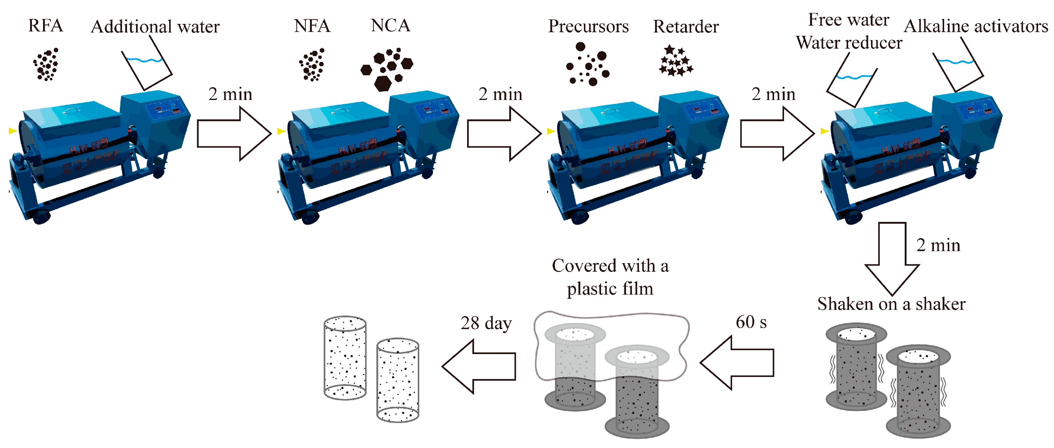
2.2.2. Preparation Methods
2.3. Test Methods
2.3.1. Slump
2.3.2. Setting Time
2.3.3. Axial Compression Test
2.3.4. SEM
3. Results and Discussion
3.1. Fresh Properties
3.2. Compressive Strength
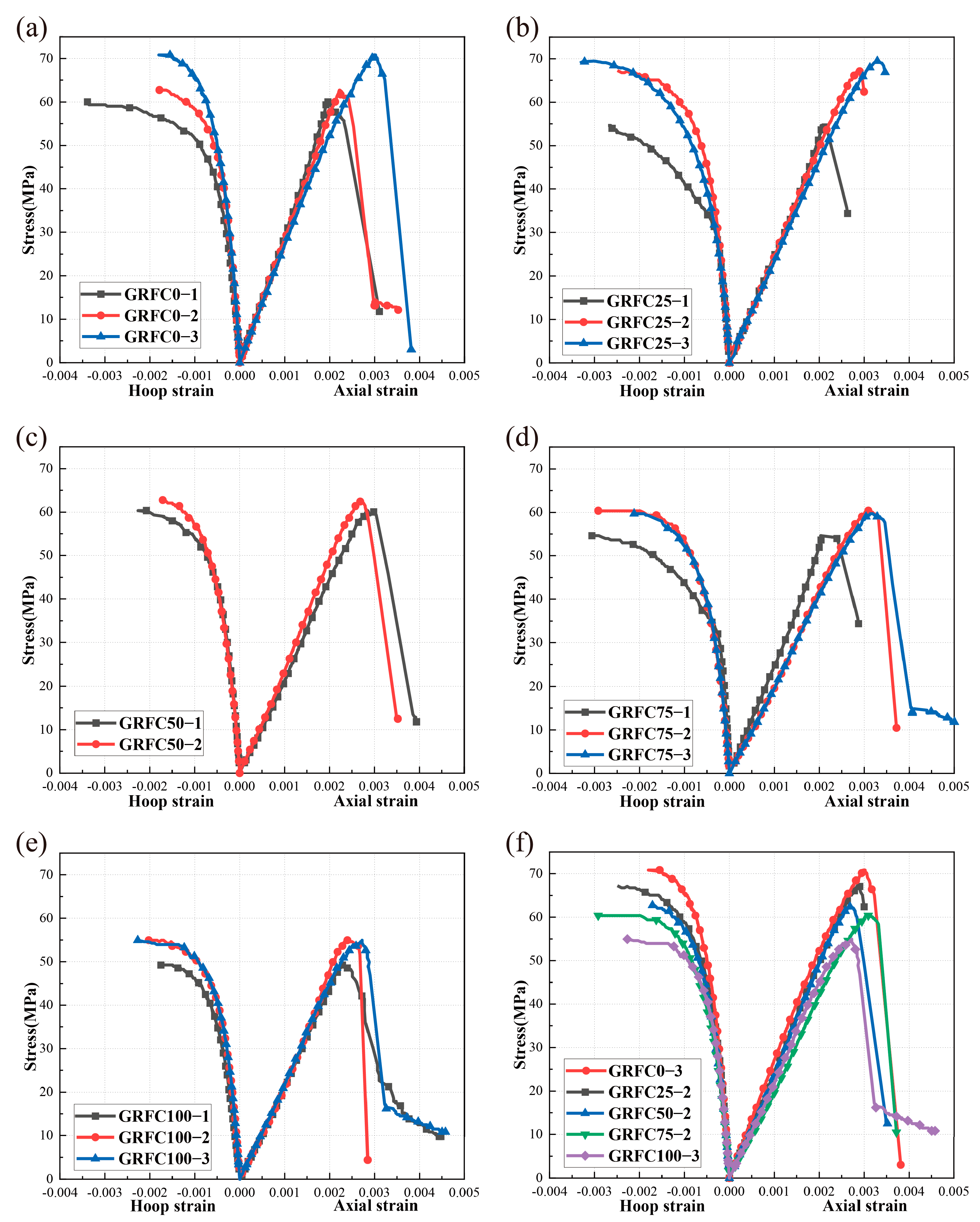
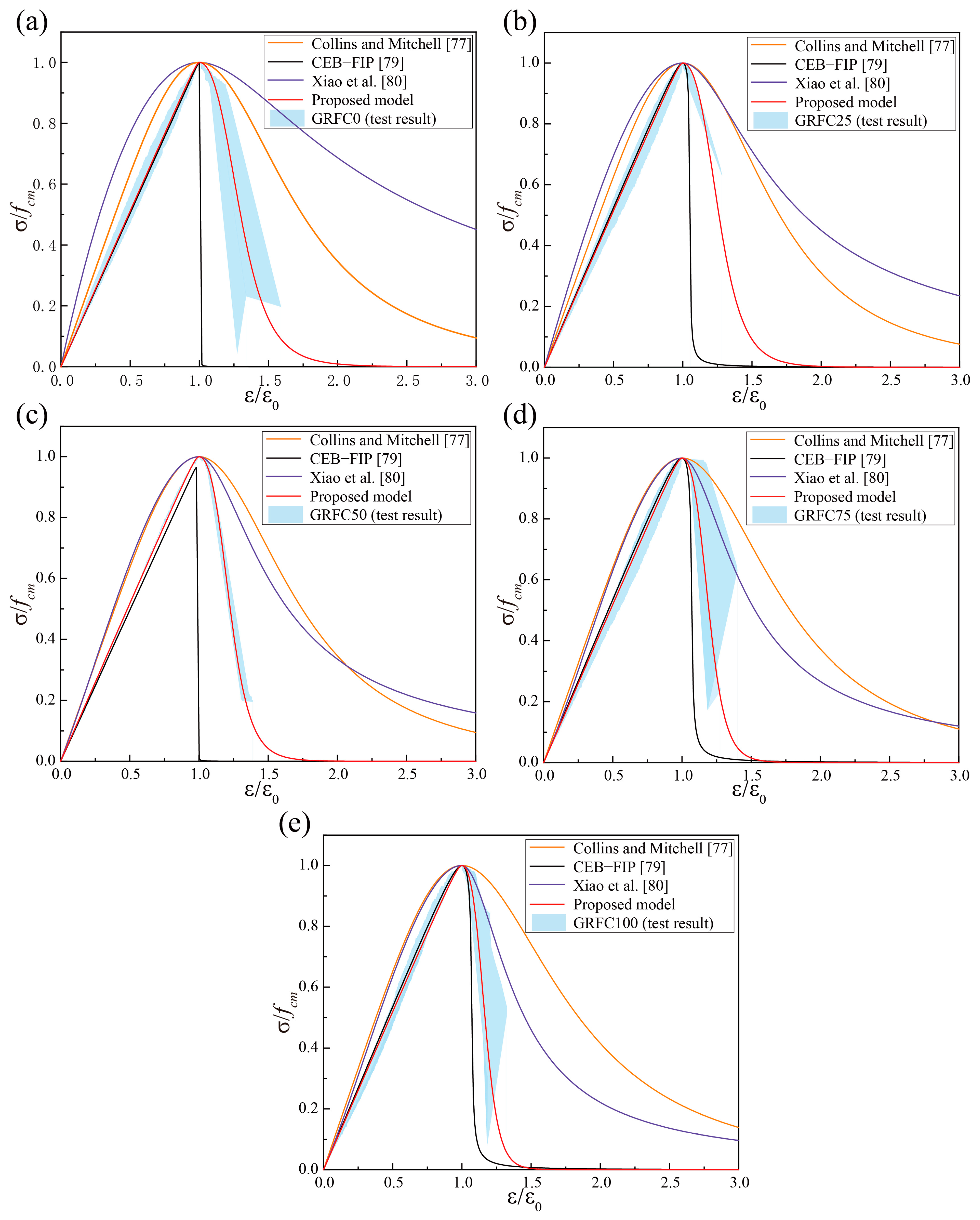
3.3. Stress–Strain Relationship
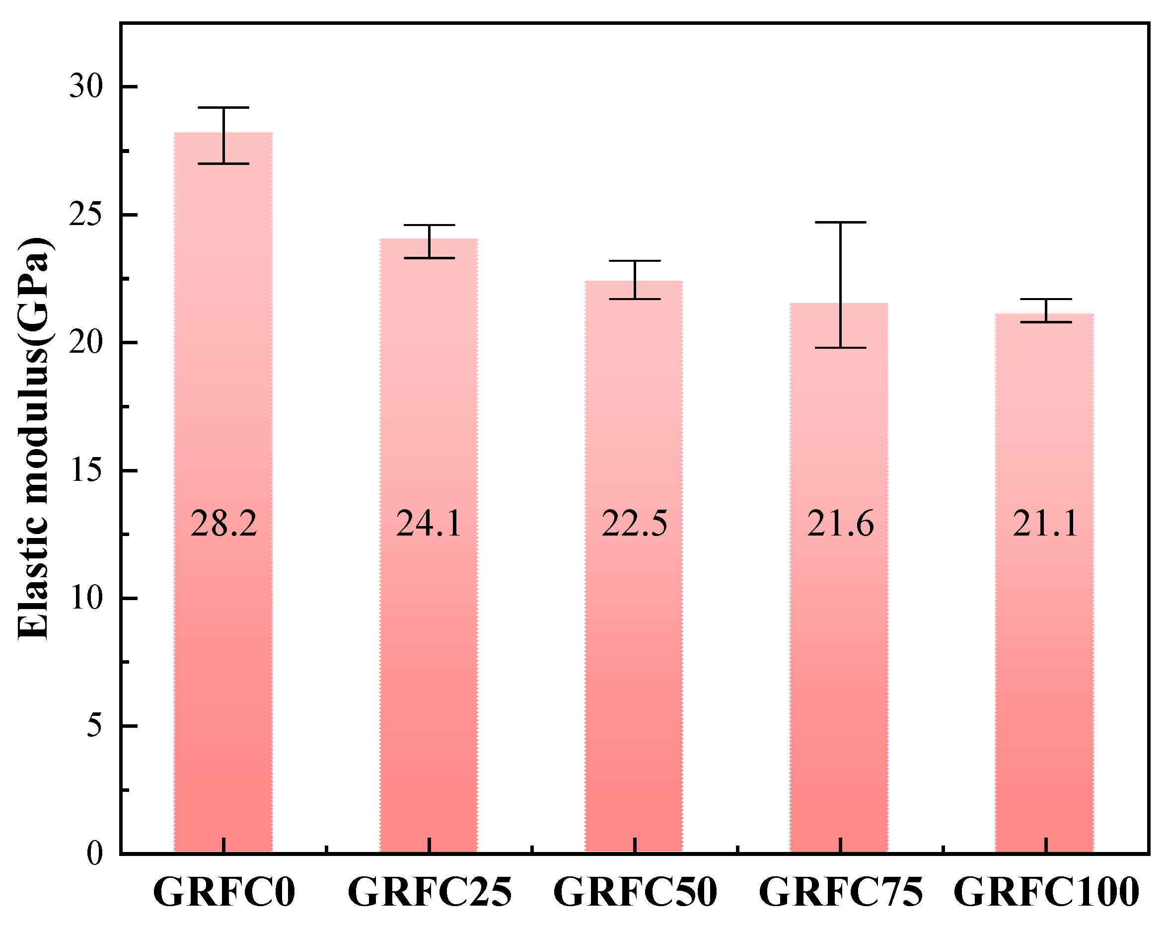
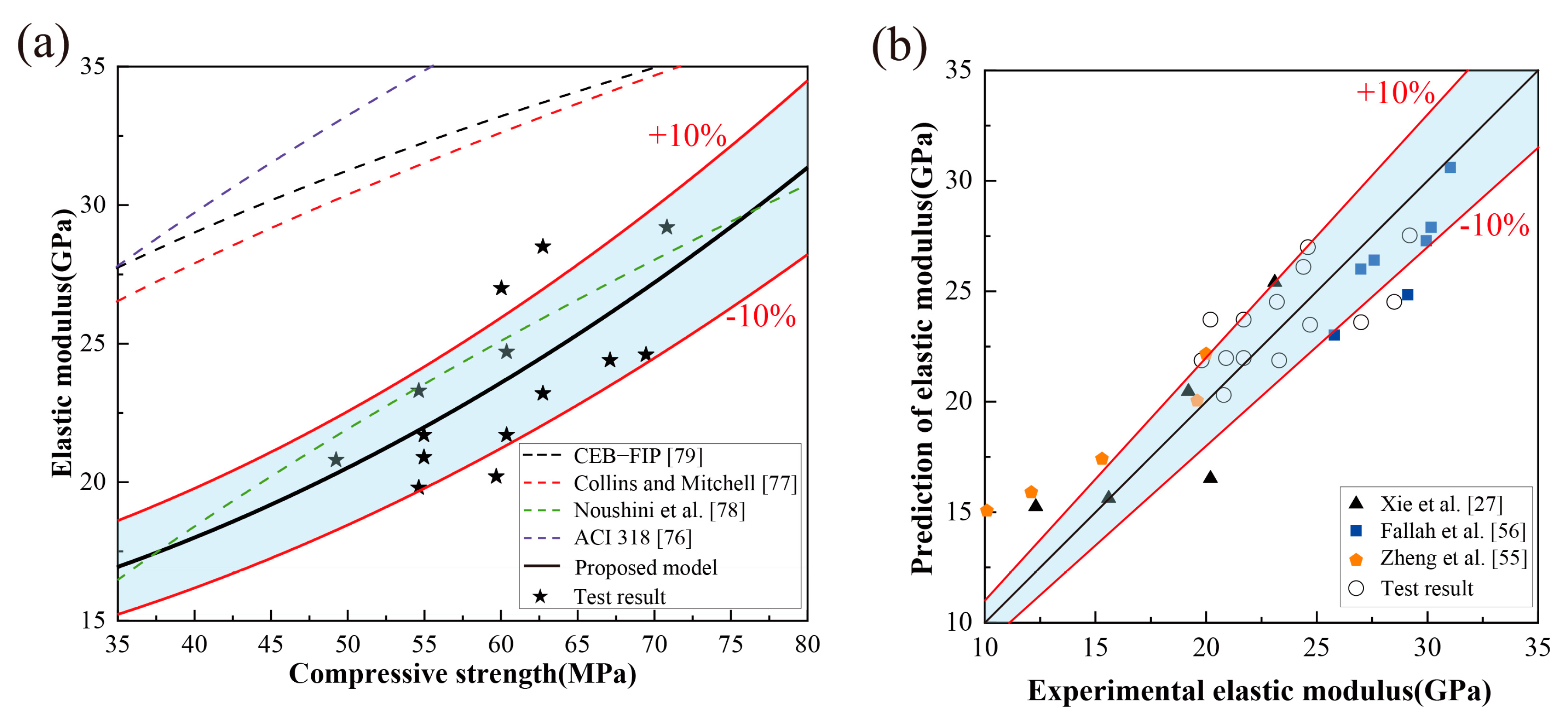
3.4. Elastic Modulus
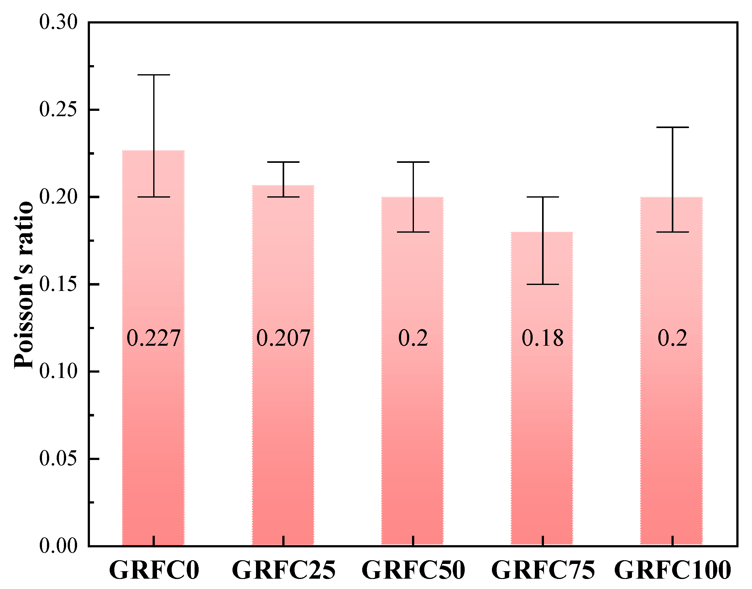
3.5. Poisson’s Ratio

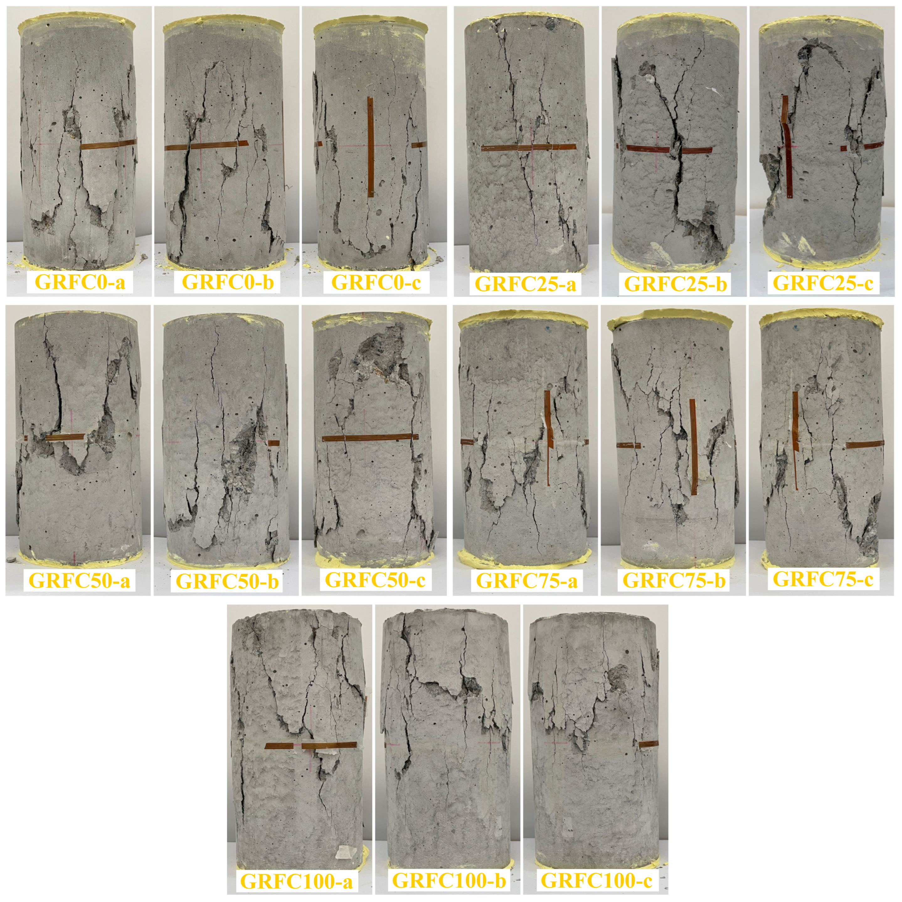
3.6. Failure Mode
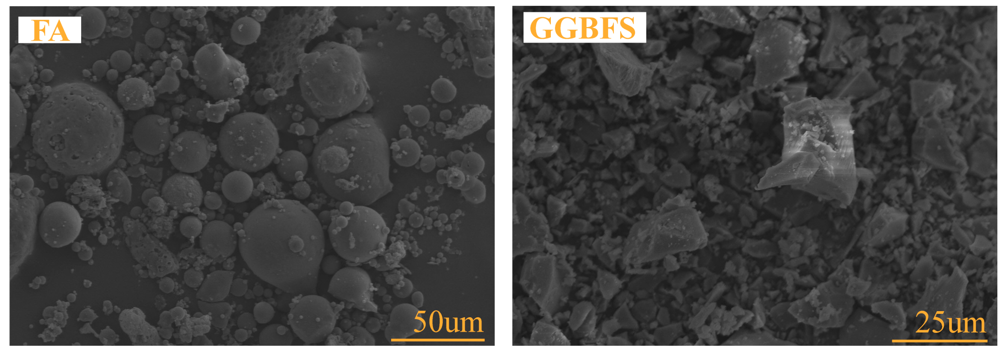
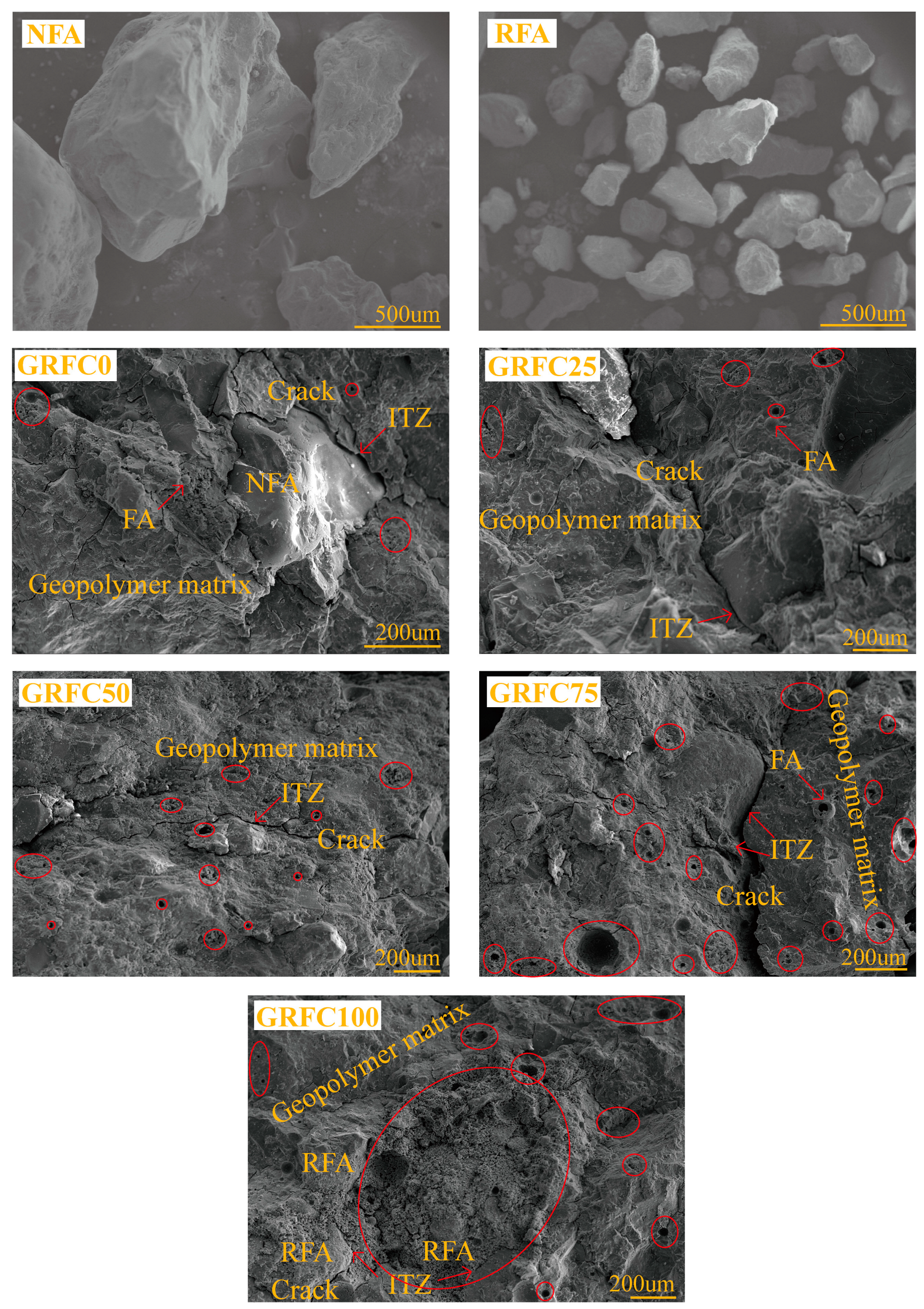
3.7. SEM Images
4. Empirical Model
4.1. Elastic Modulus Model
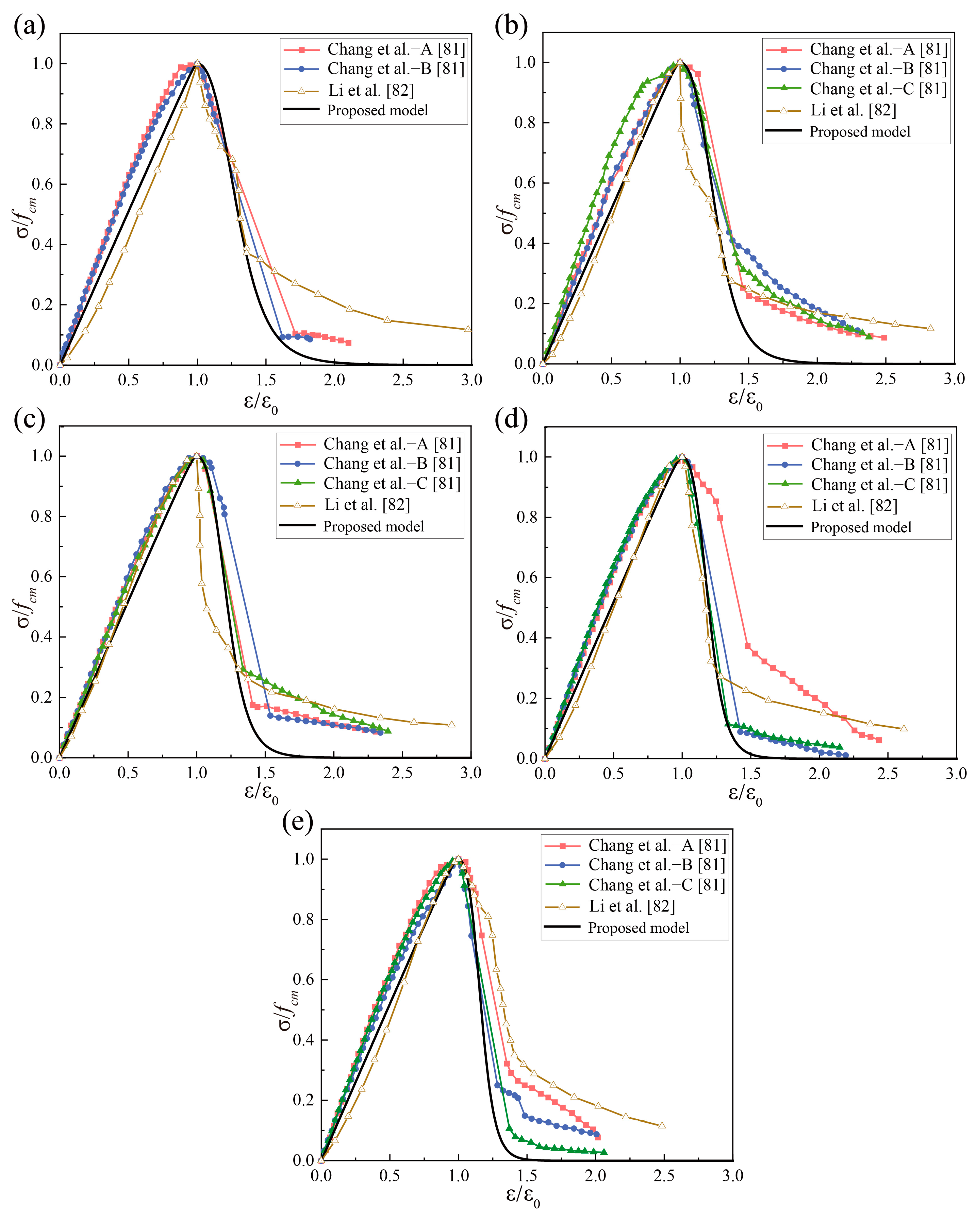
4.2. Stress–Strain Model
5. Conclusions
- (1)
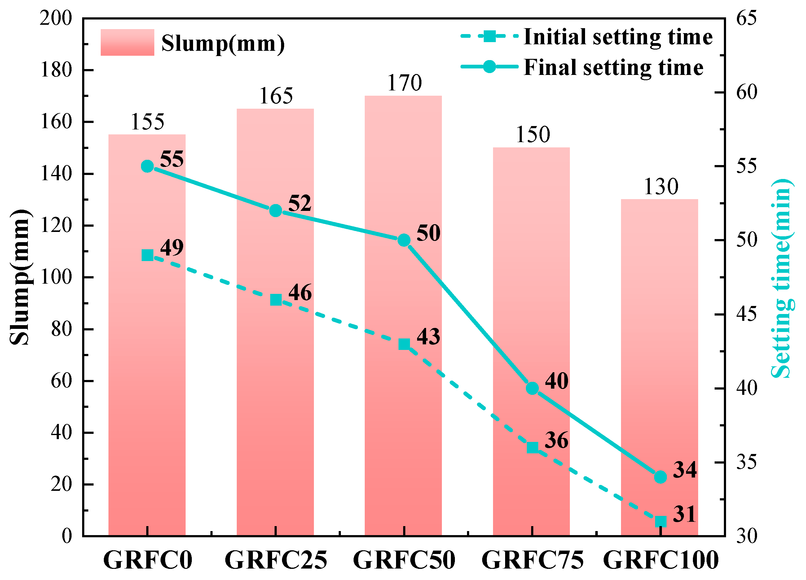
- The incorporation of RFA has a significant impact on the fresh properties of the GRFC. The higher the quantity of added RFA is, the shorter the setting time of the GRFC. In addition, a moderate amount of RFA (≤50%) can increase the fluidity of concrete. However, when the amount of RFA is more than 50%, the fluidity of concrete can become poor.
- (2)
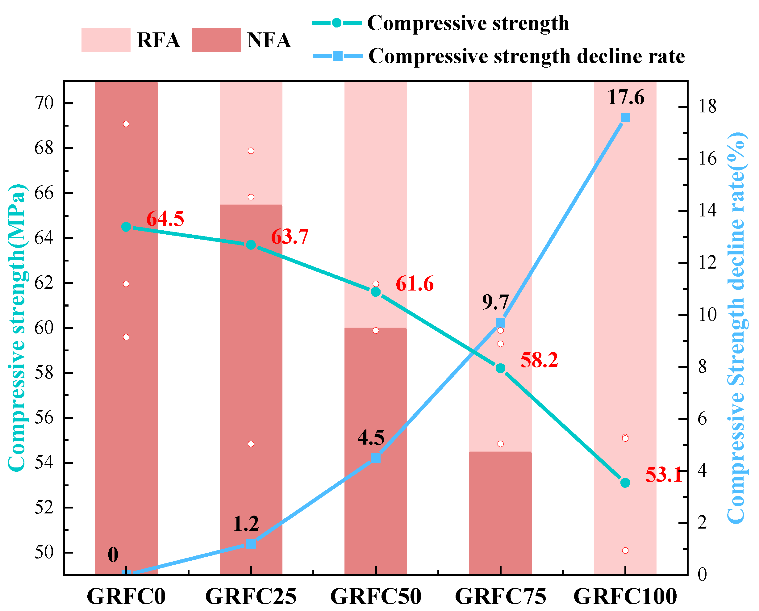
- RFAs have good adhesion to the geopolymer matrix. When the RFA content is less than 75%, the internal structure of the concrete remains dense. The strength loss is within 9.7% at a substitution ratio of 75% of the RFA.
- (3)
- The high porosity and low strength of RFA reduce the compressive strength and elastic modulus of concrete and increase the brittleness of the concrete. Partial failure occurs when the GRFC is 100% of the RFA.
- (4)
- Damage to the concrete matrix is caused mainly by the ITZs between the aggregates and the matrix. With increasing RFA, the damage is mainly concentrated at the interface associated with the attached cement.
- (5)
- The proposed prediction model performs well in predicting the stress–strain response and ultimate point of high-strength (≥50 MPa) geopolymer concrete with recycled aggregate. However, there is bias in the prediction of the 30% residual stress after the peak. A more suitable functional formula can be used to describe the stress–strain relationship in future research on recycled aggregate concrete models.
- (1)
- The RFA content in the main structural parts can be adjusted between 50% and 75% based on specific requirements, resulting in enhanced operational performance while maintaining a strength reduction within 10%.
- (2)
- The RFA can be effectively utilized in non-structural components, exhibiting a strength of 53.1 MPa.
Author Contributions
Funding
Data Availability Statement
Conflicts of Interest
References
- Schellnhuber, H.-J. Why the right climate target was agreed in Paris. Nat. Clim. Chang. 2016, 6, 649–653. [Google Scholar] [CrossRef]
- Liu, S.-W.; Tian, X.; Cai, W.-J.; Chen, W.-Q.; Wang, Y.-F. How the transitions in iron and steel and construction material industries impact China’s CO2 emissions: Comprehensive analysis from an inter sector linked perspective. Appl. Energy 2018, 211, 64–75. [Google Scholar] [CrossRef]
- Ali, M.-B.; Saidur, R.; Hossain, M.-S. A review on emission analysis in cement industries. Renew. Sustain. Energy Rev. 2011, 15, 2252–2261. [Google Scholar] [CrossRef]
- Deja, J.; Uliasz-Bochenczyk, A.; Mokrzycki, E. CO2 emissions from Polish cement industry. Int. J. Greenh. Gas Control. 2010, 4, 583–588. [Google Scholar] [CrossRef]
- Duxson, P.; Fernández-Jiménez, A.; Provis, J.-L.; Lukey, G.-C.; Palomo, A.; van Deventer, J.-S.J. Geopolymer technology: The current state of the art. J. Mater. Sci. 2007, 42, 2917–2933. [Google Scholar] [CrossRef]
- Singh, B.; Ishwarya, G.; Gupta, M.; Bhattacharyya, S.-K. Geopolymer concrete: A review of some recent developments. Constr. Build. Mater. 2015, 85, 78–90. [Google Scholar] [CrossRef]
- Chen, F.-M.; Zhao, J.-X.; Zhong, H.-C.; Feng, Y.; Chen, C.-G.; Xie, J.-H. An investigation of the durability of ultra-lightweight high-strength geopolymeric composites. J. Build. Eng. 2023, 80, 107990. [Google Scholar] [CrossRef]
- Mehta, A.; Siddique, R. An overview of geopolymers derived from industrial by-products. Constr. Build. Mater. 2016, 127, 183–198. [Google Scholar] [CrossRef]
- Li, Z.-M.; Delsaute, B.; Lu, T.-S.; Kostiuchenko, A.; Staquet, S.; Ye, G. A comparative study on the mechanical properties, autogenous shrinkage and cracking proneness of alkali-activated concrete and ordinary Portland cement concrete. Constr. Build. Mater. 2021, 292, 123418. [Google Scholar] [CrossRef]
- Zhang, Z.-H.; Yao, X.; Zhu, H.-J. Potential application of geopolymers as protection coatings for marine concrete II. Microstructure and anticorrosion mechanism. Appl. Clay Sci. 2010, 49, 7–12. [Google Scholar] [CrossRef]
- Luo, Z.-Y.; Li, W.-G.; Wang, K.-J.; Castel, A.; Shah, S.-P. Comparison on the properties of ITZs in fly ash-based geopolymer and Portland cement concretes with equivalent flowability. Cem. Concr. Res. 2021, 143, 106392. [Google Scholar] [CrossRef]
- Peng, Y.-Q.; Zheng, D.-P.; Pan, H.-S.; Yang, J.-L.; Lin, J.-H.; Lai, H.-M.; Wu, P.-Z.; Zhu, H.-Y. Strain hardening geopolymer composites with hybrid POM and UHMWPE fibers: Analysis of static mechanical properties, economic benefits, and environmental impact. J. Build. Eng. 2023, 76, 107315. [Google Scholar] [CrossRef]
- Chen, G.; Zheng, D.-P.; Chen, Y.-W.; Lin, J.-X.; Lao, W.-J.; Guo, Y.-C.; Chen, Z.-B.; Lan, X.-W. Development of high performance geopolymer concrete with waste rubber and recycle steel fiber: A study on compressive behavior, carbon emissions and economical performance. Constr. Build. Mater. 2023, 393, 131988. [Google Scholar] [CrossRef]
- Li, L.-M.; Xie, J.-H.; Zhang, B.-F.; Feng, Y.; Yang, J. A state-of-the-art review on the setting behaviours of ground granulated blast furnace slag- and metakaolin-based alkali-activated materials. Constr. Build. Mater. 2023, 368, 130389. [Google Scholar] [CrossRef]
- Behera, M.; Bhattacharyya, S.-K.; Minocha, A.-K.; Deoliya, R.; Maiti, S. Recycled aggregate from C&D waste & its use in concrete—A breakthrough towards sustainability in construction sector: A review. Constr. Build. Mater. 2014, 68, 501–516. [Google Scholar]
- Yu, A.-T.W.; Poon, C.-S.; Wong, A.; Yip, R.; Jaillon, L. Impact of Construction Waste Disposal Charging Scheme on work practices at construction sites in Hong Kong. Waste Manag. 2013, 33, 138–146. [Google Scholar] [CrossRef]
- Markssuel, M.; Paulode, M.; Erich, R.; Sergio, N.-M.; Afonso, R.-G. Recycled Aggregate: A Viable Solution for Sustainable Concrete Production. Materials 2022, 15, 5276. [Google Scholar] [CrossRef] [PubMed]
- Li, J.-L.; Feng, Y.; Zhong, H.-C.; Zhang, B.-F.; Wang, J.-J.; Zhang, B.; Xie, J.-H. Effect of the Pretreatment on the Properties of Cement-Based Recycled Powder. Coatings 2024, 14, 107. [Google Scholar] [CrossRef]
- Silva, R.-V.; de Brito, J.; Dhir, R.-K. Establishing a relationship between modulus of elasticity and compressive strength of recycled aggregate concrete. J. Clean. Prod. 2016, 112, 2171–2186. [Google Scholar] [CrossRef]
- Guo, H.; Shi, C.-J.; Guan, X.-M.; Zhu, J.-P.; Ding, Y.-H.; Ling, T.-C.; Zhang, H.-B.; Wang, Y.-L. Durability of recycled aggregate concrete—A review. Cem. Concr. Compos. 2018, 89, 251–259. [Google Scholar] [CrossRef]
- Etxeberria, M.; Vázquez, E.; Marí, A.; Barra, M. Influence of amount of recycled coarse aggregates and production process on properties of recycled aggregate concrete. Cem. Concr. Res. 2007, 37, 735–742. [Google Scholar] [CrossRef]
- Xie, J.-H.; Li, J.-L.; Zhang, B.-F.; Chen, W.; Zhong, H.-C.; Yang, J.; Yu, T.; Feng, Y. Effects of pretreated recycled fine aggregates on the mechanical properties and microstructure of alkali-activated mortar. Case Stud. Constr. Mater. 2024, 20, e02819. [Google Scholar] [CrossRef]
- Zhang, H.-R.; Ji, T.; Zeng, X.P.; Yang, Z.-X.; Lin, X.-J.; Liang, Y.-N. Mechanical behavior of ultra-high performance concrete (UHPC) using recycled fine aggregate cured under different conditions and the mechanism based on integrated microstructural parameters. Constr. Build. Mater. 2018, 192, 489–507. [Google Scholar] [CrossRef]
- Xiao, J.-Z.; Li, W.-G.; Sun, Z.-H.; Lange, D.-A.; Shah, S.-P. Properties of interfacial transition zones in recycled aggregate concrete tested by nanoindentation. Cem. Concr. Compos. 2013, 37, 276–292. [Google Scholar] [CrossRef]
- Feng, Y.; Zhang, B.-F.; Xie, J.-H.; Xue, Z.-X.; Huang, K.-H.; Tan, j.-k. Effects of recycled sand and nanomaterials on ultra-high performance concrete: Workability, compressive strength and microstructure. Constr. Build. Mater. 2023, 378, 131180. [Google Scholar] [CrossRef]
- Shi, X.-S.; Wang, Q.-Y.; Zhao, X.-L.; Frank, C. Discussion on Properties and Microstructure of Geopolymer Concrete Containing Fly Ash and Recycled Aggregate. Adv. Mater. Res. 2012, 450–451, 1577–1583. [Google Scholar] [CrossRef]
- Xie, J.-H.; Wang, J.-J.; Rao, R.; Wang, C.-H.; Fang, C. Effects of combined usage of GGBS and fly ash on workability and mechanical properties of alkali activated geopolymer concrete with recycled aggregate. Compos. Part B 2019, 164, 179–190. [Google Scholar] [CrossRef]
- Adessina, A.; Ben Fraj, A.; Barthélémy, J.-F.; Chateau, C.; Garnier, D. Experimental and micromechanical investigation on the mechanical and durability properties of recycled aggregates concrete. Cem. Concr. Res. 2019, 126, 105900. [Google Scholar] [CrossRef]
- Al-Kheetan, M.-J.; Jweihan, Y.-S.; Rabi, M.; Ghaffar, S.-H. Durability Enhancement of Concrete with Recycled Concrete Aggregate: The Role of Nano-ZnO. Buildings 2024, 14, 353. [Google Scholar] [CrossRef]
- Padmini, A.-K.; Ramamurthy, K.; Mathews, M.-S. Influence of parent concrete on the properties of recycled aggregate concrete. Constr. Build. Mater. 2009, 23, 829–836. [Google Scholar] [CrossRef]
- Katz, A. Properties of concrete made with recycled aggregate from partially hydrated old concrete. Cem. Concr. Res. 2003, 33, 703–711. [Google Scholar] [CrossRef]
- De Juan, M.-S.; Gutiérrez, P.-A. Study on the influence of attached mortar content on the properties of recycled concrete aggregate. Constr. Build. Mater. 2009, 23, 872–877. [Google Scholar] [CrossRef]
- Nuaklong, P.; Sata, V.; Chindaprasirt, P. Influence of recycled aggregate on fly ash geopolymer concrete properties. J. Clean. Prod. 2016, 112, 2300–2307. [Google Scholar] [CrossRef]
- Xie, J.-H.; Zhao, J.-B.; Wang, J.-J.; Fang, C.; Yuan, B.; Wu, Y.-H. Impact behaviour of fly ash and slag-based geopolymeric concrete: The effects of recycled aggregate content, water-binder ratio and curing age. Constr. Build. Mater. 2022, 331, 127359. [Google Scholar] [CrossRef]
- Zhu, P.-H.; Hua, M.-Q.; Liu, H.; Wang, X.-J.; Chen, C.-H. Interfacial evaluation of geopolymer mortar prepared with recycled geopolymer fine aggregates. Constr. Build. Mater. 2020, 259, 119849. [Google Scholar] [CrossRef]
- ASTM C618-22; Standard Specification for Coal Fly Ash and Raw or Calcined Natural Pozzolan for Use in Concrete. American Society Testing and Materials: West Conshohocken, PA, USA, 2023.
- Xie, J.-H.; Chen, W.; Wang, J.-J.; Fang, C.; Zhang, B.-X.; Liu, F. Coupling effects of recycled aggregate and GGBS/metakaolin on physicochemical properties of geopolymer concrete. Constr. Build. Mater. 2019, 226, 345–359. [Google Scholar] [CrossRef]
- Venu, M.; Rao, T.-D.G. Tie-confinement aspects of fly ash-GGBS based geopolymer concrete short columns. Constr. Build. Mater. 2017, 151, 28–35. [Google Scholar] [CrossRef]
- Alrefaei, Y.; Wang, Y.-S.; Dai, J.-G. The effectiveness of different superplasticizers in ambient cured one-part alkali activated pastes. Cem. Concr. Compos. 2019, 97, 166–174. [Google Scholar] [CrossRef]
- Jang, J.-G.; Lee, N.-K.; Lee, H.-K. Fresh and hardened properties of alkali-activated fly ash/slag pastes with superplasticizers. Constr. Build. Mater. 2014, 50, 169–176. [Google Scholar] [CrossRef]
- Zhang, L.-L.; Ji, Y.-S.; Li, J.; Gao, F.-R.; Huang, G.-D. Effect of retarders on the early hydration and mechanical properties of reactivated cementitious material. Constr. Build. Mater. 2019, 212, 192–201. [Google Scholar] [CrossRef]
- Oderji, S.-Y.; Chen, B.; Shakya, C.; Ahmad, M.-R.; Shah, S.-F.A. Influence of superplasticizers and retarders on the workability and strength of one-part alkali-activated fly ash/slag binders cured at room temperature. Constr. Build. Mater. 2019, 229, 116891. [Google Scholar] [CrossRef]
- Revathi, T.; Jeyalakshmi, R. Fly ash–GGBS geopolymer in boron environment: A study on rheology and microstructure by ATR FT-IR and MAS NMR. Constr. Build. Mater. 2021, 267, 120965. [Google Scholar] [CrossRef]
- Fang, G.-H.; Chen, J.-T.; Dong, B.-Q.; Liu, B. Microstructure and micromechanical properties of interfacial transition zone in green recycled aggregate concrete. J. Build. Eng. 2023, 66, 105860. [Google Scholar] [CrossRef]
- Lloyd, R.-R.; Provis, J.-L.; van Deventer, J.-S.J. Microscopy and microanalysis of inorganic polymer cements. 1: Remnant fly ash particles. J. Mater. Sci. 2009, 44, 608–619. [Google Scholar] [CrossRef]
- Kumar, S.; Kumar, R.; Mehrotra, S.-P. Influence of granulated blast furnace slag on the reaction, structure and properties of fly ash based geopolymer. J. Mater. Sci. 2010, 45, 607–615. [Google Scholar] [CrossRef]
- Kumar, G.; Mishra, S.-S. Effect of GGBFS on Workability and Strength of Alkali-activated Geopolymer Concrete. Civ. Eng. J. 2021, 7, 1036–1049. [Google Scholar] [CrossRef]
- Bakharev, T.; Sanjayan, J.-G.; Cheng, Y.-B. Resistance of alkali-activated slag concrete to acid attack. Cem. Concr. Res. 2023, 33, 1607–1611. [Google Scholar] [CrossRef]
- Hardjito, D.; Wallah, S.-E.; Sumajouw, D.-M.J.; Rangan, B.-V. On the development of fly ash-based geopolymer concrete. ACI Mater. J. 2004, 101, 467–472. [Google Scholar]
- Ryu, G.-S.; Lee, Y.-B.; Koh, K.-T.; Chung, Y.-S. The mechanical properties of fly ash-based geopolymer concrete with alkaline activators. Constr. Build. Mater. 2013, 47, 409–418. [Google Scholar] [CrossRef]
- GB/T 50080-2016; Standard for Test Method Performance of Ordinary Concrete. National Technical Committee on Cement Standardization Press: Beijing, China, 2016.
- JGJ/T70-2009; Standard for Test Method of Performance on Building Mortar. National Technical Committee on Cement Standardization Press: Beijing, China, 2009.
- ASTM C469-02; Standard Test Method for Static Modulus of Elasticity and Poisson's Ratio of Concrete in Compression. American Society Testing and Materials: West Conshohocken, PA, USA, 2017.
- Xie, J.-H.; Wang, J.-J.; Zhang, B.-X.; Fang, C.; Li, L.-J. Physicochemical properties of alkali activated GGBS and fly ash geopolymeric recycled concrete. Constr. Build. Mater. 2019, 204, 384–398. [Google Scholar] [CrossRef]
- Zheng, Y.-Q.; Zheng, L.-Y.; Wang, Y.-Q. Compressive performance and stress–strain relationship of geopolymer recycled brick aggregate concrete. Mag. Concr. Res. 2023, 75, 973–983. [Google Scholar] [CrossRef]
- Fallah, M.-A.; Mousavinejad, S.-H.G. A Comparative Study of Properties of Ambient-Cured Recycled GGBFS Geopolymer Concrete and Recycled Portland Cement Concrete. J. Mater. Civ. Eng. 2023, 35, 5022002. [Google Scholar] [CrossRef]
- Huang, J.-G.; Zou, C.-Y.; Sun, D.; Yang, B.; Yan, J.-C. Effect of recycled fine aggregates on alkali-activated slag concrete properties. Structures 2021, 30, 89–99. [Google Scholar] [CrossRef]
- Pasupathy, K.; Ramakrishnan, S.; Sanjayan, J. Influence of recycled concrete aggregate on the foam stability of aerated geopolymer concrete. Constr. Build. Mater. 2021, 271, 121850. [Google Scholar] [CrossRef]
- Lee, W.-K.W.; van Deventer, J.-S.J. The effect of ionic contaminants on the early-age properties of alkali-activated fly ash-based cements. Cem. Concr. Res. 2002, 32, 577–584. [Google Scholar] [CrossRef]
- Fan, C.-C.; Huang, R.; Hwang, H.; Chao, S.-J. Properties of concrete incorporating fine recycled aggregates from crushed concrete wastes. Constr. Build. Mater. 2016, 112, 708–715. [Google Scholar] [CrossRef]
- Rifa, A.; Subhani, S.-M.; Bahurudeen, A.; Santhosh, K.-G. A systematic comparison of performance of recycled concrete fine aggregates with other alternative fine aggregates: An approach to find a sustainable alternative to river sand. J. Build. Eng. 2023, 78, 107695. [Google Scholar] [CrossRef]
- Ju, M.; Park, K.; Park, W.-J. Mechanical Behavior of Recycled Fine Aggregate Concrete with High Slump Property in Normal- and High-Strength. Int. J. Concr. Struct. Mater. 2019, 13, 61. [Google Scholar] [CrossRef]
- Sinha, A.-K.; Talukdar, S. Enhancement of the properties of silicate activated ultrafine-slag based geopolymer mortar using retarder. Constr. Build. Mater. 2021, 313, 125380. [Google Scholar] [CrossRef]
- Venu, M.; Gunneswara Rao, T.-D. An Experimental Investigation of the Stress-Strain Behaviour of Geopolymer Concrete. Slovak J. Civ. Eng. 2018, 26, 30–34. [Google Scholar] [CrossRef]
- Li, B.; Gao, A.-X.; Li, Y.; Xiao, H.-L.; Chen, N.; Xia, D.-T.; Wang, S.-B.; Li, C.-N. Effect of silica fume content on the mechanical strengths, compressive stress–strain behavior and microstructures of geopolymeric recycled aggregate concrete. Constr. Build. Mater. 2023, 384, 131417. [Google Scholar] [CrossRef]
- Xie, J.-H.; Huang, L.; Guo, Y.-C.; Li, Z.-J.; Fang, C.; Li, L.-J.; Wang, J.-J. Experimental study on the compressive and flexural behaviour of recycled aggregate concrete modified with silica fume and fibres. Constr. Build. Mater. 2018, 178, 612–623. [Google Scholar] [CrossRef]
- Gesoglu, M.; Güneyisi, E.; Öz, H.-Ö.; Taha, I.; Yasemin, M.-T. Failure characteristics of self-compacting concretes made with recycled aggregates. Constr. Build. Mater. 2015, 98, 334–344. [Google Scholar] [CrossRef]
- Geng, J.; Chen, Y.-Y.; Sun, J.-Y.; Chen, W. Basic Mechanics Characters of Recycled Fine Aggregate Concrete. Adv. Mater. Res. 2012, 446–449, 2028–2032. [Google Scholar] [CrossRef]
- Hasnaoui, A.; Ghorbel, E.; Wardeh, G. Performance of metakaolin/slag-based geopolymer concrete made with recycled fine and coarse aggregates. J. Build. Eng. 2021, 42, 102813. [Google Scholar] [CrossRef]
- Shi, C.-J.; Li, Y.-K.; Zhang, J.-K.; Li, W.-G.; Chong, L.-L.; Xie, Z.-B. Performance enhancement of recycled concrete aggregate—A review. J. Clean. Prod. 2016, 112, 466–472. [Google Scholar] [CrossRef]
- Dilbas, H.; Simsek, M.; Çakir, Ö. An investigation on mechanical and physical properties of recycled aggregate concrete (RAC) with and without silica fume. Constr. Build. Mater. 2014, 61, 50–59. [Google Scholar] [CrossRef]
- Zhang, M.-M.; Zhu, L.-H.; Gao, S.; Dong, Y.-R.; Yuan, H.-Q. Mechanical properties of recycled aggregate concrete prepared from waste concrete treated at high temperature. J. Build. Eng. 2023, 76, 107045. [Google Scholar] [CrossRef]
- Li, J.; Chen, L.-L.; Wang, Z.-F.; Wang, Y.-Q. Effect of Modification and Replacement Rate of Recycled Coarse Aggregate on Properties of Recycled Aggregate Concrete. Iran. J. Sci. Technol. 2023, 47, 3321–3332. [Google Scholar] [CrossRef]
- Fang, C.-L.; Feng, J.-C.; Huang, S.-S.; Hu, J.; Wang, W.; Li, N. Mechanical properties and microscopic characterization of mortar with recycled aggregate from waste road. Case Stud. Constr. Mater. 2022, 17, e01441. [Google Scholar] [CrossRef]
- Hu, Y.; Tang, Z.; Li, W.-G.; Li, Y.-N.; Tam, V.-W.Y. Physical-mechanical properties of fly ash/GGBFS geopolymer composites with recycled aggregates. Constr. Build. Mater. 2019, 226, 139–151. [Google Scholar] [CrossRef]
- ACI 318-19; Building Code Requirements for Structural Concrete and Commentary. American Concrete Institute: Indianapolis, IN, USA, 2019.
- Collins, M.-P.; Mitchell, D.; Macgregor, J.-G. Structural Design Considerations for High-Strength Concrete. Concr. Int. 1993, 15, 27–34. [Google Scholar]
- Noushini, A.; Aslani, F.; Castel, A.; Gilbert, R.-I.; Uy, B.; Foster, S. Compressive stress-strain model for low-calcium fly ash-based geopolymer and heat-cured Portland cement concrete. Cem. Concr. Compos. 2016, 73, 136–146. [Google Scholar] [CrossRef]
- CEB-FIP Model Code 2010: Design Code; Comite Euro-International Du Beton: Lausanne, Switerland, 2013.
- Xiao, J.-Z.; Li, J.-B.; Zhang, C. Mechanical properties of recycled aggregate concrete under uniaxial loading. Cem. Concr. Res. 2005, 35, 1187–1194. [Google Scholar] [CrossRef]
- Chang, Y.-C.; Wang, Y.-Y.; Zhang, H.; Chen, J.; Geng, Y. Different influence of replacement ratio of recycled aggregate on uniaxial stress-strain relationship for recycled concrete with different concrete strengths. Structures 2022, 42, 284–308. [Google Scholar] [CrossRef]
- Li, B.; Wu, F.; Xia, D.-T.; Li, Y.; Cui, K.; Wu, F.-H.; Yu, J.-L. Compressive and flexural behavior of alkali-activated slag-based concrete: Effect of recycled aggregate content. J. Build. Eng. 2023, 67, 105993. [Google Scholar] [CrossRef]


| Precursor | SiO2 | Al2O3 | CaO | Fe2O3 | TiO2 | MgO | Others |
|---|---|---|---|---|---|---|---|
| FA | 56.74 | 24.58 | 4.87 | 6.55 | 1.86 | --- | 5.4 |
| GGBFS | 33.21 | 15.76 | 37.14 | 0.71 | 1.91 | 8.51 | 2.76 |
| Density (g/cm3) | Na2O (wt.%) | SiO2 (wt.%) | H2O (wt.%) | |
|---|---|---|---|---|
| NaOH | 1.32 | 18.78 | - | 81.22 |
| Na2SiO3 | 1.384 | 8.9 | 28.8 | 62.2 |
| NFA | RFA | NCA | |
|---|---|---|---|
| Grain size (mm) | 0.075~4.75 | 0.075~4.75 | 5~20 |
| Apparent density (g/cm3) | 2627.8 | 2558.1 | 2653.7 |
| Water absorption (%) | 0.83 | 10.53 | 0.9 |
| Fineness modulus | 1.64 | 1.64 | -- |
| Compression properties (%) | -- | -- | 9.8 |
| Mix | NCA | NFA | RFA | FA | GGBFS | NaOH | Na2SiO3 | W | AW | B | S |
|---|---|---|---|---|---|---|---|---|---|---|---|
| GRFC0 | 1155 | 495 | 0 | 125 | 375 | 125.7 | 126.4 | 26.6 | 0 | 20 | 10 |
| GRFC25 | 371.2 | 123.8 | 12 | ||||||||
| GRFC50 | 247.5 | 247.5 | 24 | ||||||||
| GRFC75 | 123.8 | 371.2 | 36 | ||||||||
| GRFC100 | 0 | 495 | 48 |
| References | Scope of Application | Formulas | |
|---|---|---|---|
| CEB–FIP [79] | Normal-strength and high-strength concrete | (4) | |
| Collins and Mitchell [77] | Normal-strength and high-strength concrete | (5) | |
| Noushini et al. [78] | Fly ash-based geopolymer concrete | (6) | |
| ACI 318 [76] | Normal-strength and high-strength concrete | (7) |
Disclaimer/Publisher’s Note: The statements, opinions and data contained in all publications are solely those of the individual author(s) and contributor(s) and not of MDPI and/or the editor(s). MDPI and/or the editor(s) disclaim responsibility for any injury to people or property resulting from any ideas, methods, instructions or products referred to in the content. |
© 2024 by the authors. Licensee MDPI, Basel, Switzerland. This article is an open access article distributed under the terms and conditions of the Creative Commons Attribution (CC BY) license (https://creativecommons.org/licenses/by/4.0/).
Share and Cite
Zhong, H.; Fu, H.; Feng, Y.; Li, L.; Zhang, B.; Chen, Z.; Lu, Z.; Xie, J. Compressive Behaviors of High-Strength Geopolymeric Concretes: The Role of Recycled Fine Aggregate. Buildings 2024, 14, 1097. https://doi.org/10.3390/buildings14041097
Zhong H, Fu H, Feng Y, Li L, Zhang B, Chen Z, Lu Z, Xie J. Compressive Behaviors of High-Strength Geopolymeric Concretes: The Role of Recycled Fine Aggregate. Buildings. 2024; 14(4):1097. https://doi.org/10.3390/buildings14041097
Chicago/Turabian StyleZhong, Huaicheng, Huanchang Fu, Yuan Feng, Liming Li, Baifa Zhang, Zhanbiao Chen, Zhongyu Lu, and Jianhe Xie. 2024. "Compressive Behaviors of High-Strength Geopolymeric Concretes: The Role of Recycled Fine Aggregate" Buildings 14, no. 4: 1097. https://doi.org/10.3390/buildings14041097