Article

Experimental Study on Repairing/Restoration and Reinforcement Methods of the Reinforced Concrete Structures Damaged by Earthquakes

School of Civil Architectural Engineering, North China University of Science and Technology, Tangshan 063000, China
*
Author to whom correspondence should be addressed.
Buildings 2024, 14(4), 1102; https://doi.org/10.3390/buildings14041102
Submission received: 6 September 2023 / Revised: 31 January 2024 / Accepted: 10 February 2024 / Published: 15 April 2024
(This article belongs to the Section Building Structures)

Abstract

:
For earthquake-damaged reinforced concrete structures, the static loading test method is adopted to carry out loading tests under cyclic loading on reinforced concrete beams with different reinforcement rates and columns with different axial compression ratios, and the effect of reinforcing and repairing the damaged reinforced concrete structure by using adhesive steel plates and carbon fiber cloth is investigated. Through comparative studies of structural hysteresis curves and skeleton curves under different reinforcement methods, it is concluded that reinforcement has significantly improved the hysteresis characteristics and ductility of members, and the seismic performance of the carbon fiber reinforcement method is better than that of the steel plate reinforcement. This study provides valuable references and suggestions for practical earthquake-damaged building reinforcement and repair works and seismic reinforcement works.

1. Introduction

In recent years, with economic growth and technological progress, reinforced concrete structures remain the most dominant structural form and are widely used in the housing construction industry. However, due to design defects, poor construction quality, changes in functional use, and improper maintenance, many buildings have suffered from insufficient structural bearing capacity during use [1]. In order to eliminate potential safety hazards, a series of effective reinforcement methods have emerged, such as new materials including bonded steel plates, carbon fibers, and structural adhesives, as well as advanced techniques such as drilling and implanting steel reinforcement [2]. Aiming at the problems of reinforced concrete structures with adhesive steel and carbon fibers, scholars at home and abroad have conducted a lot of research. As early as the 1960s, countries such as the United States, the Soviet Union, and Japan began to use steel plate reinforcement technology. With time, this reinforcement method has widely been recognized and applied.
In 2005, Liu [3] used the separation method to establish a finite element model of reinforced concrete beams, and the model was dynamically analyzed under the action of simple harmonic concentrated loads and modal analysis. The analysis results showed that the vibration mode of reinforced concrete beams changed after reinforcement, and the ultimate dynamic load-deflection-frequency curves of concrete cracking in the bottom tensile zone also showed the dynamic characteristics of reinforced concrete beams under the action of simple harmonic concentrated dynamic loads.
In 2006, Sheng [4] designed three shear walls according to the old and new codes, respectively, and carried out comparative pseudo-static load tests and theoretical analysis on one of the reinforcements made of steel to study the role of steel reinforcement and the seismic performance of medium and high shear walls. The results showed that the use of u-type steel plates to reinforce the hidden columns of shear walls significantly improved the load-carrying capacity of the specimens, improved the ductility and energy dissipation performance of the specimens, stabilized the late stiffness of the structure, and the hysteresis curves of the specimens were more adequate, which effectively improved the seismic performance of the shear walls.
In 2008, Xie [5] investigated the calculation of load-carrying capacity and deformation of cohesive reinforced concrete beams under bending moments, and solved the load-deflection curves of cohesive reinforced concrete beams by using the layered finite element method. The results showed that the method of reinforcing the reinforced concrete flexural members with steel is effective and the flexural capacity of the beams was significantly improved after the steel plates were adhered.
In 2008, Guo [6] conducted an experimental study on one-sided bonded reinforced concrete beams, and based on the results of the study and the actual floor reinforcement requirements, the double-sided bonded reinforced concrete floor technique was proposed for the first time. Combined with the cross-section internal force equilibrium relationship, the formulas for bending capacity and cross-section stiffness of double-sided bonded reinforced floors were derived considering that the floor reinforcement process was not completely unloaded. At the same time, he proposed two methods to improve the bonding effect between steel plates and floor slabs.
In 2010, Yu [7] performed finite element analysis of reinforced concrete frame nodes reinforced with steel reinforcement using ANSYS software (https://www.ansys.com/zh-cn, accessed on 5 September 2023) to simulate the action of low circumferential cyclic loads. He compared the numerical analysis with experimental data in order to verify the effect of reinforcing different thicknesses of reinforcement materials on the nodal force and hysteresis curves.
In 2019, Liu [8] conducted static tests on four reinforced, bent steel columns and one unreinforced, bent steel column for comparison to investigate the effects of the thickness of the affixed steel plate and the load eccentricity on the force performance of the bonded steel reinforcement. The results show that all five bent steel columns exhibited spatial bending and torsional instability damage, and that bonding steel plates outside the flange can effectively improve the out-of-plane stabilization of bent steel columns. The results also showed the web section of reinforced bent steel columns. The plastic development of the web section of the bent steel column is more obvious, and the eccentricity is the main factor affecting the stabilizing capacity after reinforcement.
In 2021, Zhang [9] considered the strain lagging effect of reinforced steel plates and derived the formula for calculating the lagging strain of prestressed concrete beams and the tensile strength reduction factor of reinforced steel plates. The formula for calculating the final bending capacity of prestressed concrete beams with viscous steel reinforcement was derived based on the relative height of the compression zone of viscous-steel-reinforced prestressed concrete beams being 0.85 times of the control value of the steel reinforcement before reinforcement.
Unlike adhesive reinforcement, carbon fiber reinforcement uses high-strength, highly elastic carbon fiber material to improve the load-carrying capacity and durability of the structure. This reinforcement method has the advantages of simple construction, light weight, and limited impact on the original structure, and is widely used in modern building structure reinforcement.
In 2001, Thanasis C. [10] conducted shear tests on reinforced concrete beams reinforced with carbon fiber fabric. The results show that carbon fiber reinforcement can effectively improve the shear and deformation capacities of the beams and correspondingly increase the ductility of the reinforced beams.
In 2003, Lu [11] conducted low weak repetitive tests on five concrete nodes strengthened with carbon fibers. Analysis showed that the seismic performance and ultimate bearing capacity of the reinforced nodes were significantly improved, and the performance indexes were in accordance with the requirements of the current seismic code in China. Wang [6] proposed an equation for calculating the stiffness of a reinforced beam section at three damage stages through tests on 12 concrete beams.
In 2004, Liu [12] studied carbon-fiber-fabric-reinforced concrete beams and found that the pre-cracking degree has little effect on the ultimate bearing capacity of the reinforced beams, but it significantly impacts the strain and sectional stiffness of the reinforcement. The higher the degree of pre-cracking, the better the reinforcement effect.
In 2009, Pan [13] studied reinforced concrete columns using static elasto-plastic analysis, programmed using OpenSees (https://opensees.berkeley.edu/wiki/index.php/OpenSees_User, accessed on 5 September 2023). On this basis, the specific eigen parameters of the constrained columns were investigated and the effect of the specific eigen relationships on the moment–curvature relationship at the level of the column cross-section was explored.
In 2010, Wang [14] investigated the reinforcement performance of Carbon Fiber Reinforced Plastics (CFRP) for repairing reinforced concrete pipes damaged by earthquakes. The damage characteristics, crack formation conditions, and ultimate bearing capacity were investigated for different reinforcement materials and different damage levels.
In 2016, Xu [15] conducted a low-cycle reciprocating load damage test, and the results showed that the specimens under compression, bending, and shear composite stresses all showed bending and shear damage, which satisfied the seismic requirements of “strong shear, weak bending”, and the average increase in the ultimate load of a column damaged by a moderate earthquake was 10.41%, and the average increase in the ultimate displacement was 35.40%. The average increase in ultimate load and ultimate displacement of moderate earthquake-damaged columns are 10.41% and 35.40%, respectively.
In 2018, Xu [16] conducted a low circumferential reciprocating load damage test on samples reinforced and repaired with carbon fiber cloth after simulating different seismic damages. The test results showed that the carbon fiber cloth improved the ultimate bearing capacity, ultimate displacement, and ductility coefficient of the samples.
In 2022, Zhou [17] used fiber cloth of the same width as the bottom of the beam to inhibit the interface peel damage of narrow beams reinforced with pure adhesive sheets. The end of the fiber cloth was wound around the joint plate, self-locking, and suspended with buckle bolts and side plates, forming a side-hanging hybrid anchor carbon fiber cloth reinforcement by synergistic sticking. Bending tests were carried out on seven reinforced concrete narrow beams. The results showed that with the increase in the length of the carbon fiber cloth, the starting position of the peel damage of the fully bonded (using the full length of the fiber cloth) beam shifted from the end to the middle, and the peel load increased slightly.
According to the existing literature, the mainstream reinforcement schemes mainly include steel plate reinforcement and carbon fiber reinforcement. This study mainly adopts the method of combining theoretical analysis and experimental research to deeply study the effects of these reinforcement schemes. Firstly, we designed and made six reinforced concrete beams and columns. Subsequently, two-step experiments were carried out on these samples. The first step was to conduct damage tests to evaluate the performance of the damaged samples. The second step was to carry out carbon fiber reinforcement and steel plate reinforcement on the “damaged samples”, and analyze the seismic performance of the reinforced samples. These experiments aimed to explore the effects of different reinforcement methods on the seismic performance of the samples, and provide a theoretical basis and practical guidance for improving the seismic performance of building structures.

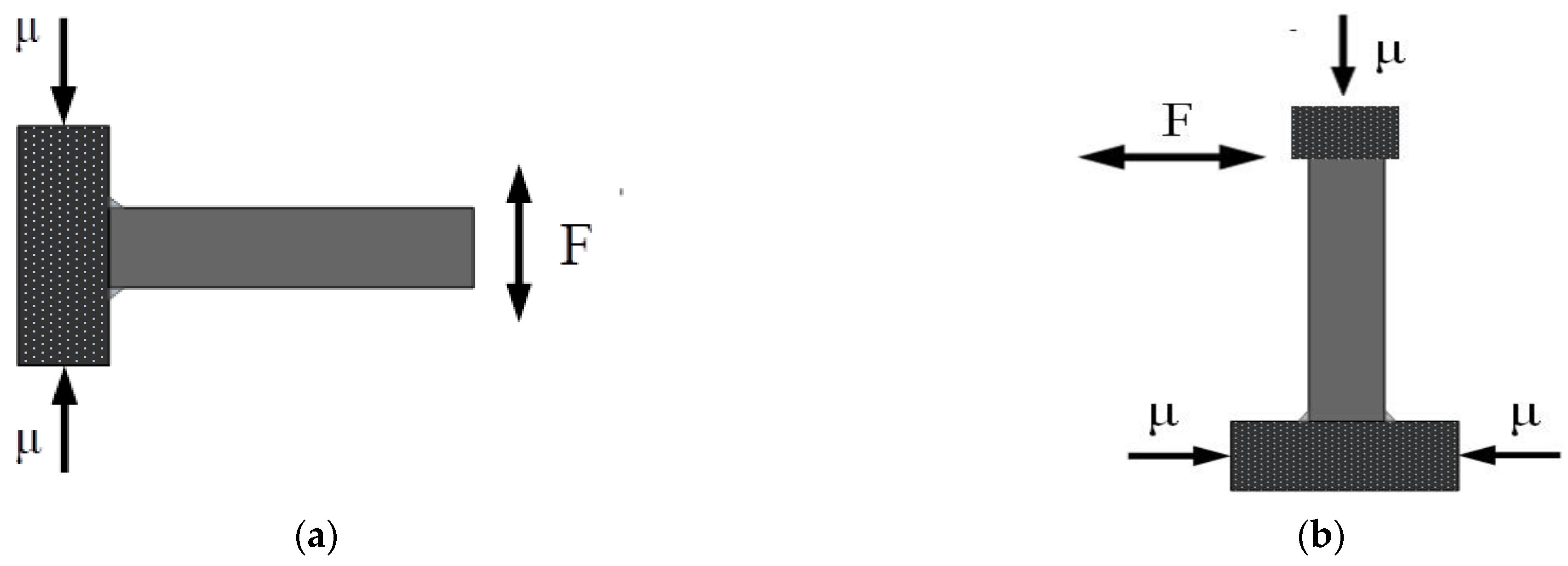
2. Reinforcement Principle

Reinforced concrete structural components include reinforced concrete columns, shear walls, beams, slabs, etc. This study mainly focuses on beams and columns as the primary research objects. The load-bearing capacity of components depends on various factors, including material strength grade, amount of steel, cross-sectional size of components, and the length, height, or span of components. Therefore, to improve the load-bearing capacity of concrete structures, methods such as increasing material grade, increasing steel usage, enlarging cross-sectional size, or reducing component length, height, or span can be adopted [18,19,20,21].
Based on the principle of reinforcing reinforced concrete structures, scientific researchers and engineers have developed various reinforcement methods suitable for concrete structures, as shown in Table 1.
The method of enlarging the cross-section is one of the most widely applicable reinforcement methods, suitable for strengthening not only flexural members (slabs, beams) and compressive members (large eccentric compression, small eccentric compression, axial compression) of reinforced concrete, but also tension members (roofs) and shear members (shear walls). Its advantages and disadvantages are evident. Its advantages include mature construction technology, good reinforcement effect, clear and reliable force transmission, and low reinforcement cost. Its disadvantages include significantly increasing the original cross-sectional size of concrete members, increasing the dead weight of the structure, reducing the effective use space of the building, and wasting the building area.
Both bonding steel plates and bonding carbon fiber cloth involve adhering steel plates/carbon fiber cloth to the surface of concrete members using adhesive to form a holistic force-bearing component; thereby, improving the load-bearing capacity and ductility of the original structural members.
The method of bonding steel plates is quick and simple, with minimal impact on the building’s appearance and usable space. It does not significantly affect residents’ lives and production activities, and the weight increase after reinforcement is relatively small. To prevent rusting of the steel plates and improve the durability of the reinforcement, anti-corrosion and waterproof treatment is required on the surface of the steel plates and adjacent concrete [22,23,24,25,26].
Carbon fiber cloth is lightweight and high strength, with good durability and corrosion resistance. It can fully utilize its high elastic modulus and high-strength properties to enhance the ductility and load-bearing capacity of members. It does not require drilling or punching holes in the original concrete structure; therefore, it does not damage the reinforced structure, does not change the shape of the building, and does not affect the appearance. However, its fire resistance is poor, and the reinforcement construction requires high bonding technique. The compatibility and permeability between the two are poor, and the water permeability and breathability are relatively poor.

3. Specimens and Experimental Methods

The specimens were reinforced concrete beams with different reinforcement ratios and reinforced concrete columns with different axial compression ratios, and the Mechanical Testing & Simulation (MTS) dynamic system device was used to perform low-cycle repeated load tests on the test pieces horizontally. Steel plates and carbon fiber cloth were used to reinforce and repair the damaged beams and columns, and secondary load tests were conducted. By analyzing the skeleton curves, ductility performance, energy consumption performance, hysteresis curves, and stiffness degradation of the specimens, the influence of different reinforcement and repair methods on the seismic performance of the structure was discussed and analyzed.

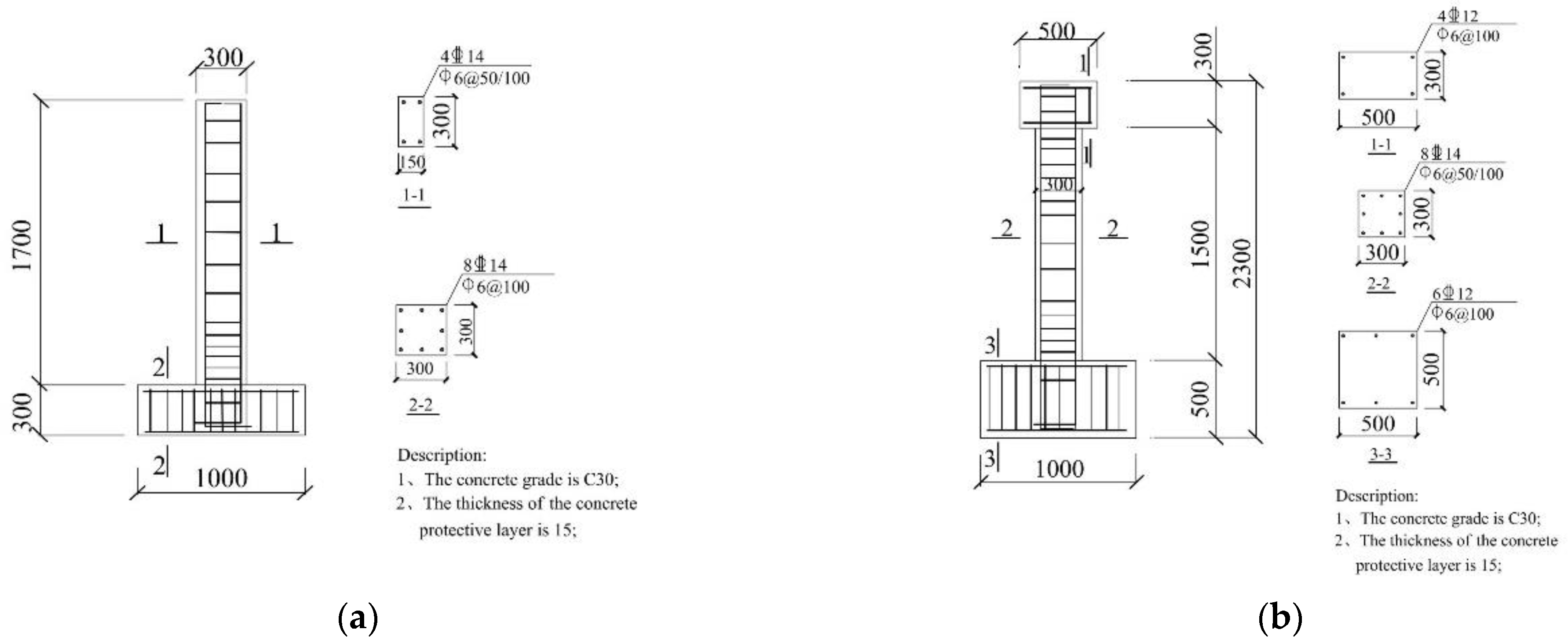
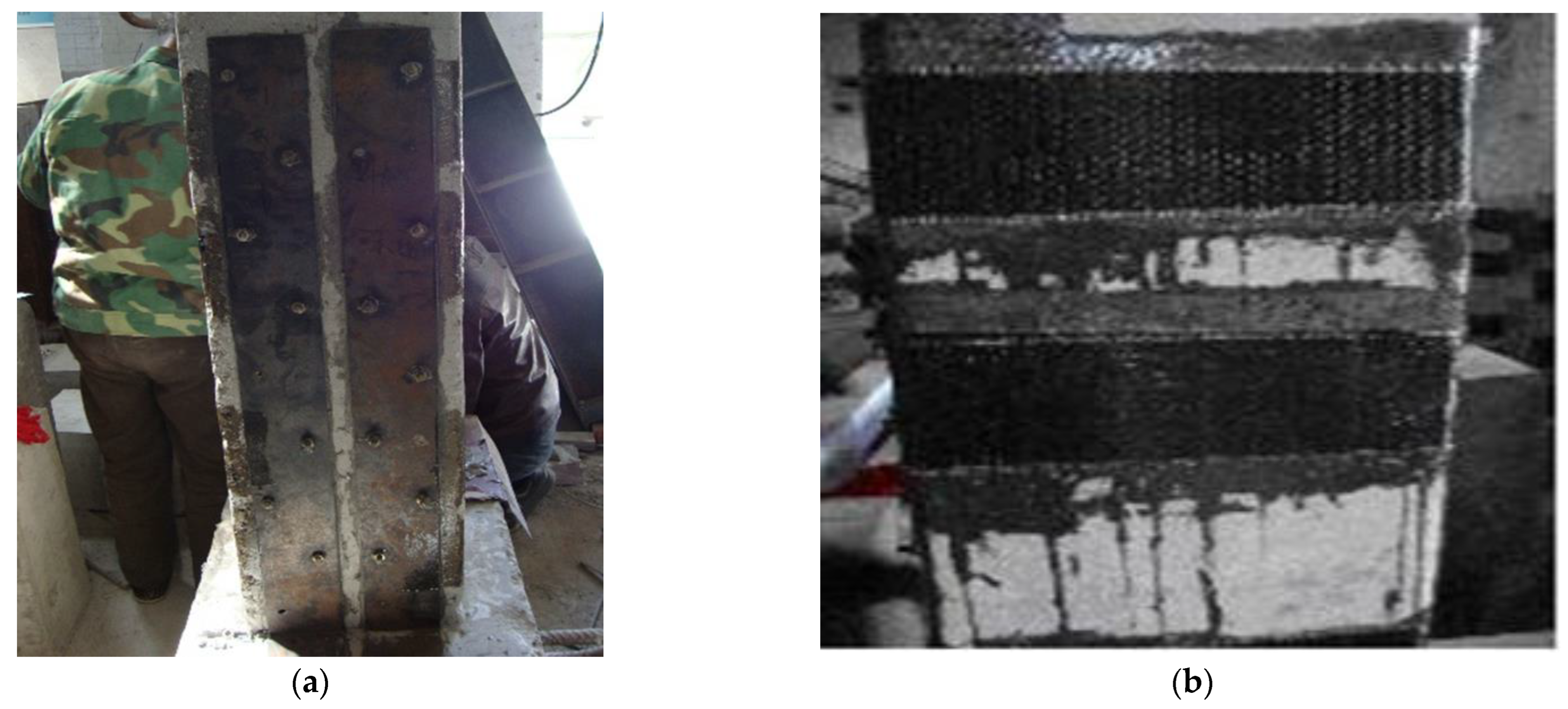
3.1. Beam Specimens and Column Specimens

Framed structural beams are generally load-bearing components with constrained beam ends. Under external loads, cracks or even failure usually occur at the beam ends or mid-span. This batch of specimens includes 10 components, including 6 suitable reinforced beams with the numbers L0, L1, L2, L3, L4, and L5 and 4 reinforced beams with damage, numbered JL1, JL2, JL3, and JL4.
Framed structural columns are generally horizontal load-bearing components with a certain axial compression ratio and constrained ends under earthquake action. Under external loads, cracks or even failure usually occur at the column ends. This batch of specimens includes 10 components, including 6 suitable reinforced columns with the numbers Z0, Z1, Z2, Z3, Z4, and Z5, and 4 reinforced columns with damage, numbered JZ1, JZ2, JZ3, and JZ4. (Ordinary steel beams and columns are denoted by “L” and “Z”, while reinforced and repaired beams and columns are prefixed with “J” for “reinforced” and “S” for “damaged” for comparative test components. Reinforced and repaired beams and columns are indicated by “J” in front of the number to indicate “reinforced”, while comparative test components are preceded by “S” to indicate “damaged”.) In the first step, low circumferential reciprocating damage tests were performed on specimens L0-L5 and Z0-Z5, which were defined as SL0, SL5, SZ0, and SZ5 after one instance of damage, and in the second step, carbon fiber reinforcement and steel plate reinforcement were performed on the other post-damage specimens L1-L4 and Z1-Z4; then, low-circumferential reciprocating tests were performed on the reinforced specimens JL1-JL4 and JZ1-JZ4. In this study, a reinforced concrete beam end specimen was used as a “t-shape” specimen, as shown in Figure 1a. The column specimen connected to the beam end shown in Figure 1b was subjected to axial pressure, and its stiffness was designed to be large enough to achieve a fixed end restraint at the beam end; thus, exhibiting a failure mode of damage at the beam end. Figure 1 shows the axial pressure applied, with F indicating the applied low-cycle reciprocating load. In this study, reinforced concrete column specimens were tested using a cross-section between the bending point of the load-bearing frame column and the beam-column node. The dimensions of the frame column specimen were half of the height of the original frame column. As shown in Figure 1b, μ is the applied axial pressure, F is the applied low-cycle reciprocating cyclic load.
According to the “Code for Design of Reinforcing Concrete Structures” for both beams and columns, the carbon fiber reinforcement was dimensioned with transverse horizontal strips bonded at a spacing of 200 mm and a width of 100 mm. For steel plate reinforcement, the transverse horizontal strips were bonded at a spacing of 200 mm and a width of 100 mm. The dimensions and reinforcements of the beam specimens and column specimens in the experiment are shown in Table 2 and Figure 2.

3.2. Material Properties

The longitudinal reinforcement in the beam and column specimens adopted HRB400 grade, and the stirrups adopted HRB235 grade double-leg stirrups. The mechanical properties of the steel were tested in accordance with the “Metal Tensile Test Method”, and the mechanical properties of the steel are shown in Table 3. The beam and column specimens in this study adopted pumped commercial concrete with a design strength of C30. The concrete splitting tensile strength was measured after curing the standard cubic specimen of 150 mm × 150 mm× 150 mm for 28 days, and the axial compressive strength of the concrete was measured using a prismatic specimen of 150 mm× 150 mm × 300 mm. Table 4 shows the mechanical properties of the concrete.

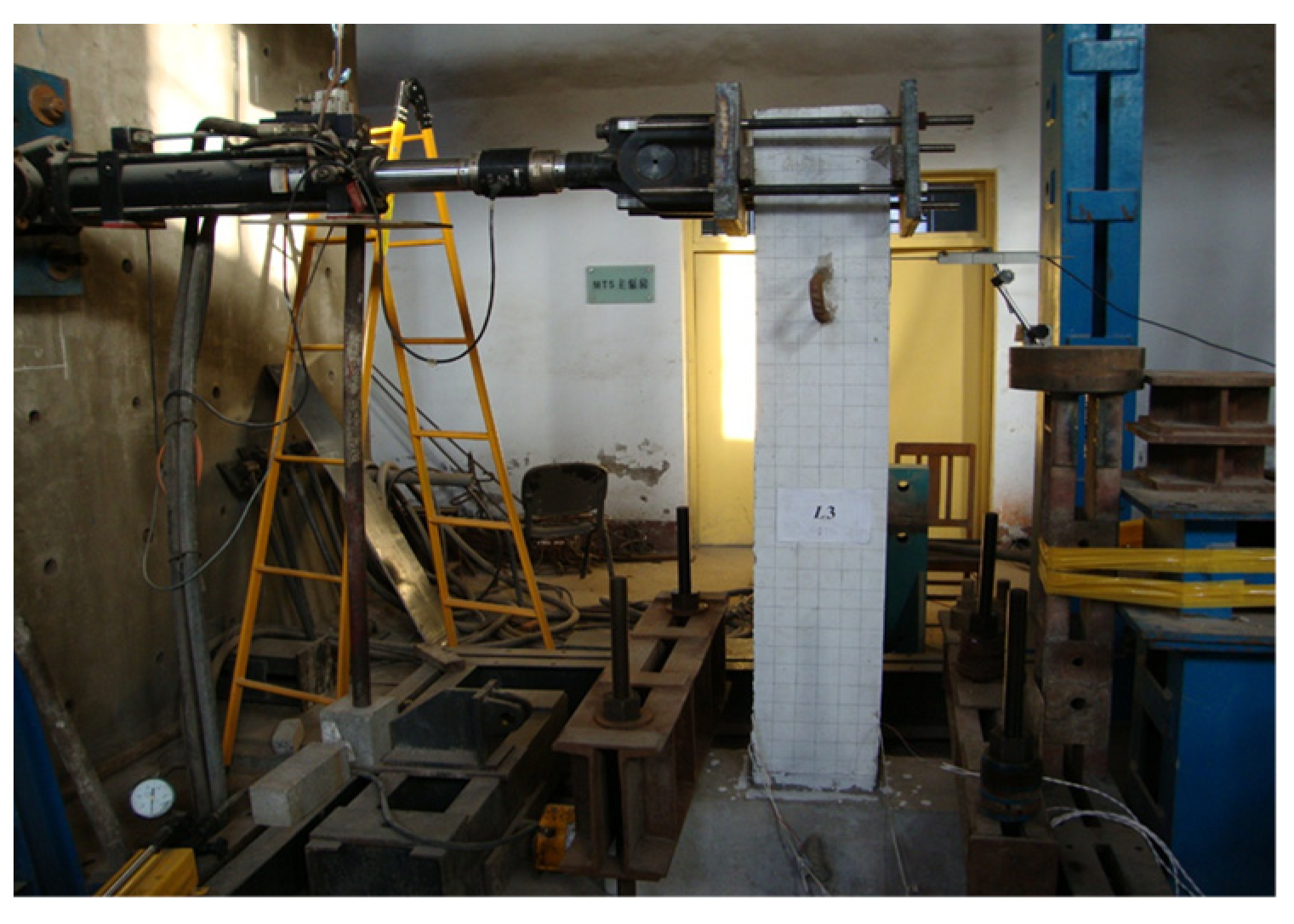
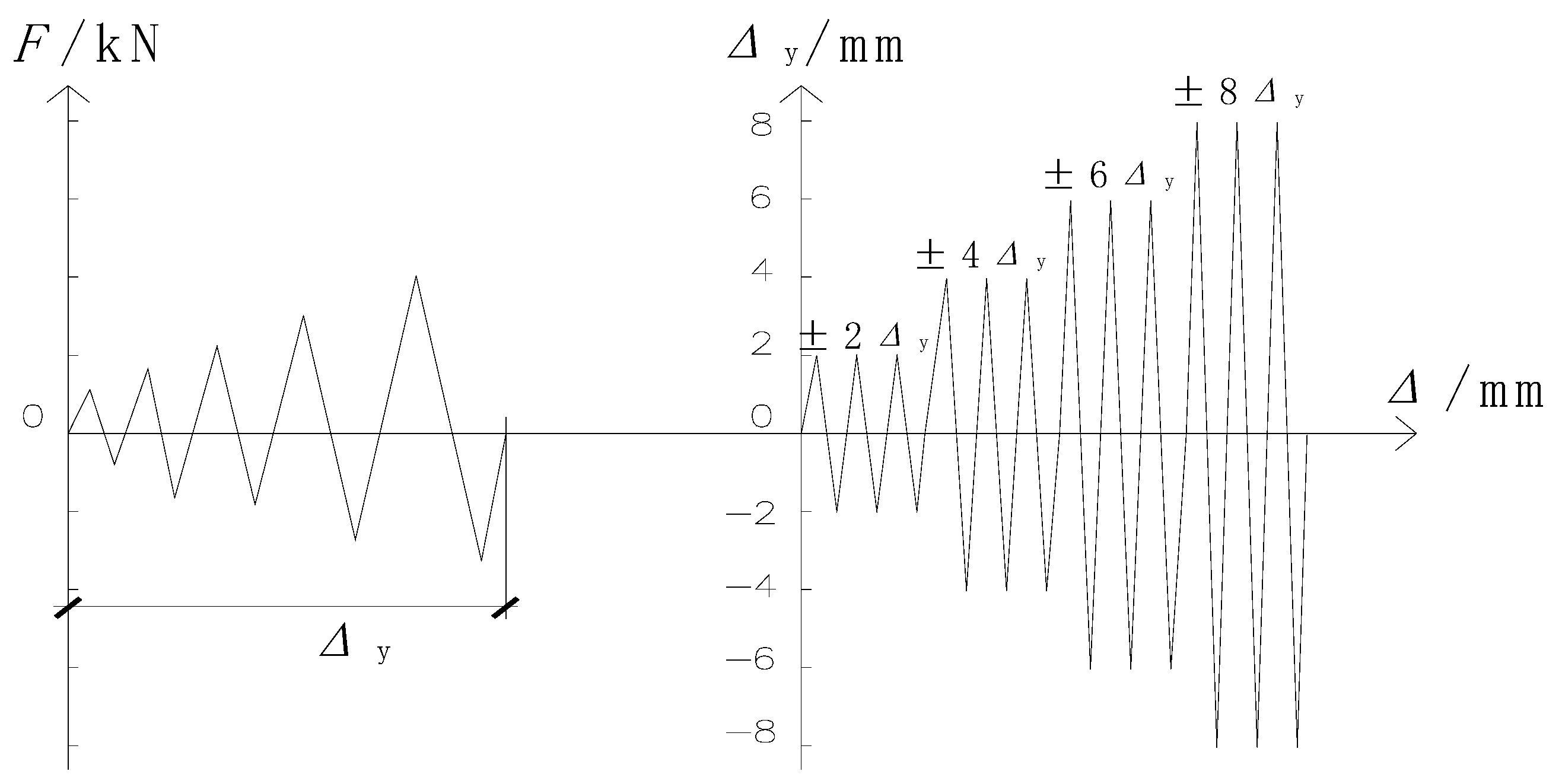
3.3. Test Device and Loading System

In this study, the MTS pseudo-dynamic system device was used with a hybrid load-displacement-controlled loading method. The device is shown in Figure 3. The loading was gradually increased for control before the rebar was created; after the rebar was created, the displacement of the member was controlled. Each loading was 5 mm and there were two cycles followed by 10 mm, 15 mm, 20 mm, 25 mm, and 30 mm. The loading system and component loading diagrams are shown in Figure 4 and Figure 5. For reinforced beams and columns, the pre-repair loading method was repeated for comparison.
For each load, the strain was recorded on a longitudinal rebar strain gauge, the average deformation of the concrete was measured with a hand-held strain gauge, cracks were described and the crack widths, lengths, and spacing were recorded. As the yield was approached, the amount of loading was reduced appropriately to measure more accurate failure loads.

4. Results and Discussion

4.1. Analysis of Skeleton Curves of Reinforced Concrete Components after Damage Repairing and Reinforcement

The skeleton curve is the envelope line of the peak points of each cycle in the hysteresis curve, which is the outer envelope line of the hysteresis curve. In general, the skeleton curve of a structure is similar to the corresponding load-displacement curve under a monotonic loading, which can clearly reflect the strength, deformation, and other properties of the structure. As shown in Figure 6, SL0 and JL2 are comparison beams and carbon-fiber-reinforced beams in the secondary test with a steel ratio of 4 14. In Figure 7, SZ0 and JZ2 are the skeleton curves of comparison columns and carbon-fiber-reinforced columns in the secondary test with an axial compression ratio of 0.2.
  • It is clear from the above figure that the reinforced beam and column specimens went through the whole process from elastic phase to yielding phase and finally to the final phase. Comparison of the load-carrying capacity, overall stiffness, and deformation capacity of the reinforced members shows significant improvement as compared to the pre-strengthened members.
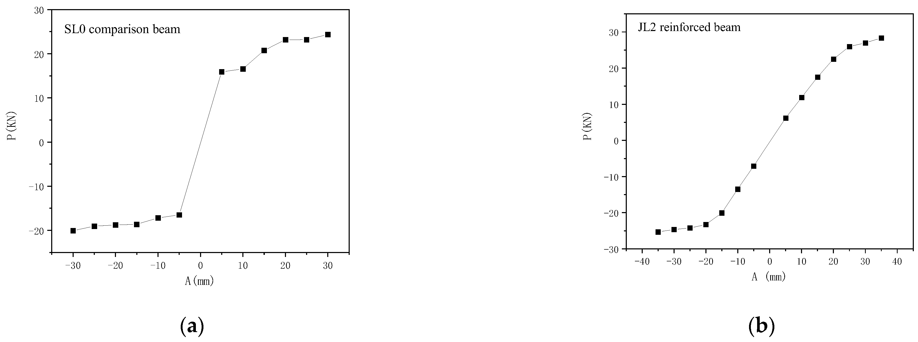
  • The stress–strain curve of JL2 is basically linear when the displacement loading is ±10 mm. Thereafter, with the increase in displacement load, the elastic phase of the post-earthquake damage specimen is obviously longer than that of the pre-earthquake damage specimen, and the yield load is greatly increased. When the displacement load reaches ±50 mm, the lateral force basically no longer increases and the ductility is very good.
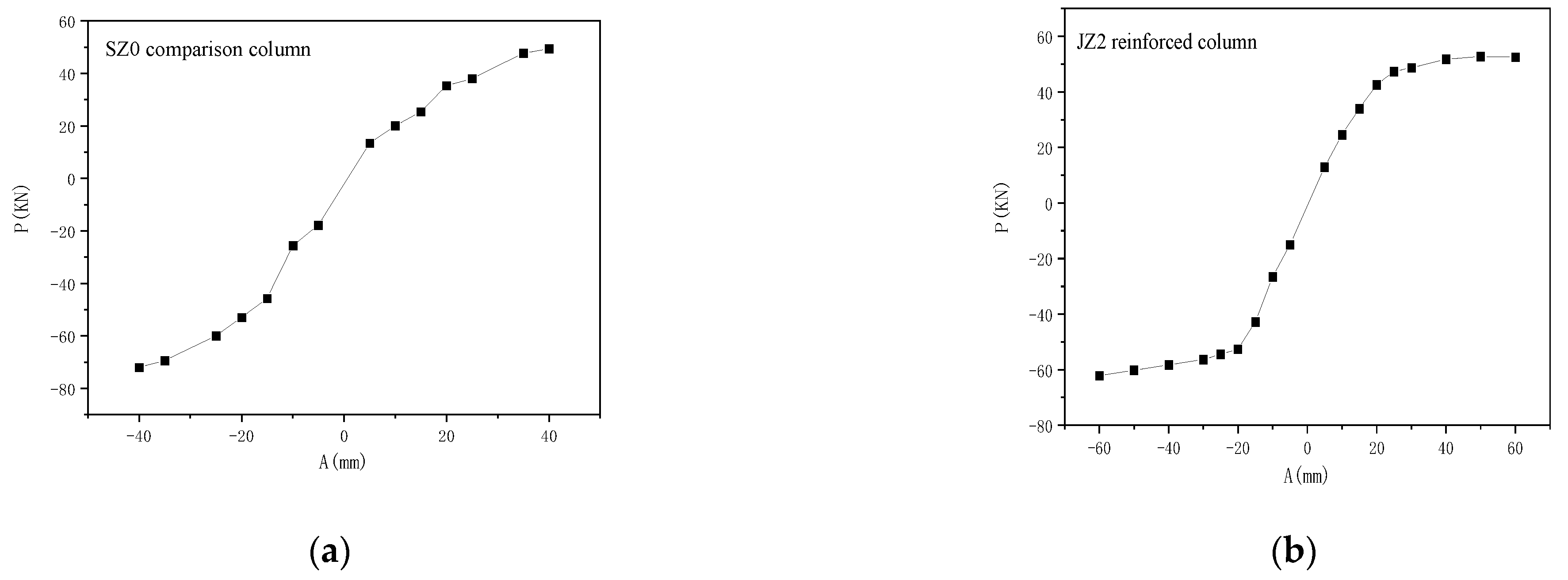
  • When the displacement loading reaches ±20 mm, the stress–strain curve of JZ2 is basically linear. Thereafter, with the increase in displacement load, the increase in lateral force decreases rapidly until the displacement is loaded to ±50 mm, the lateral force basically stops increasing, showing good ductility.

4.2. Analysis of Ductility Performance of Damaged Reinforced Concrete Components after Strengthening and Repairing

In order to measure and compare the ductility of structures or materials, a clear numerical indicator is required, usually expressed as ductility or ductility ratio. It is defined as the ratio of the ultimate deformation to the initial yield deformation while maintaining the basic bearing capacity (strength) of the structure or material.
The ductility coefficient can be calculated using Equation (1):
μ d = u y = u + + u y + + y
  • Δu, Δy—The ultimate displacement and yield displacement of a structural member can generally be determined by the lateral displacement corresponding to the point on the load-displacement curve where the horizontal load drops to the nominal limit load. In this article, the nominal limit load is taken to be the load value at which the horizontal load drops to 85% of the limit load.
  • Δu+, Δu—positive and negative limit displacement of the component.
  • Δy+, Δy—positive and negative yield displacement of the component.
The calculation results of the ductility coefficients of each component are shown in Table 5 and Table 6.
1
Comparison of JL1, JL2, JL3, and JL4 shows that the ductility coefficients of carbon-fiber-reinforcing bars are 9.1% and 8.1% higher than that of steel-plate-reinforcing bars, respectively.
2
Comparison of JZ1, JZ2, JZ3, and JZ4 shows that the ductility coefficients of carbon-fiber-reinforcing bars are 8.7% and 8% higher than that of steel-plate-reinforcing bars, respectively.
3
This shows that carbon fiber reinforcement is more capable of withstanding plastic deformation of the structure than steel plate reinforcement.

4.3. Analysis of Energy Dissipation Performance of Damaged Reinforced Concrete Components after Strengthening and Repairing

Under a cyclic loading, the area enclosed by the load-displacement curve and the displacement axis of the specimen represents the amount of energy absorbed or dissipated by the specimen. The area enclosed by the unloading curve and the displacement axis represents the amount of energy released by the specimen. The area enclosed within the hysteresis loop after one cycle of loading represents the amount of energy dissipated by the specimen. The comparison of the energy dissipation performance of damaged concrete structures after strengthening and repairing can be seen in Table 7 and Table 8.
  • Analysis of the data in Table 7 shows an average increase of 58.5% in seismic energy dissipation capacity for the carbon-fiber-reinforced beam end specimens compared to the unreinforced comparison analysis, and an average increase of 30.5% in seismic energy dissipation capacity for the steel-reinforced specimens compared to the unreinforced comparison members analysis.
  • Analysis of the data in Table 8 shows that the average increase in seismic energy dissipation capacity of carbon-fiber-reinforced columns over unreinforced comparison columns is 45%, and the average increase in energy dissipation capacity of steel-plate-reinforced columns over unreinforced comparison columns is 22%.

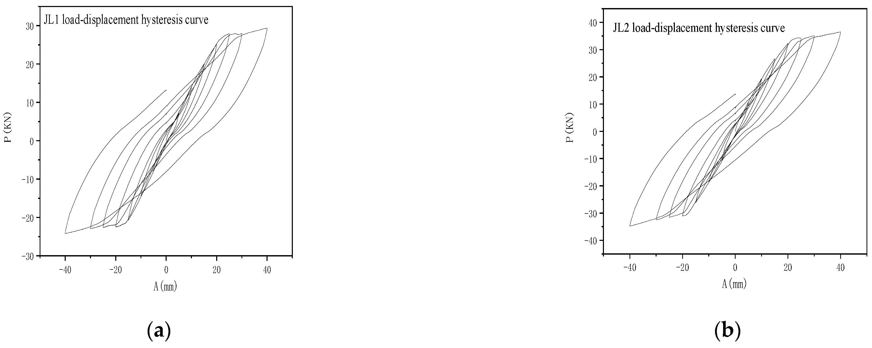
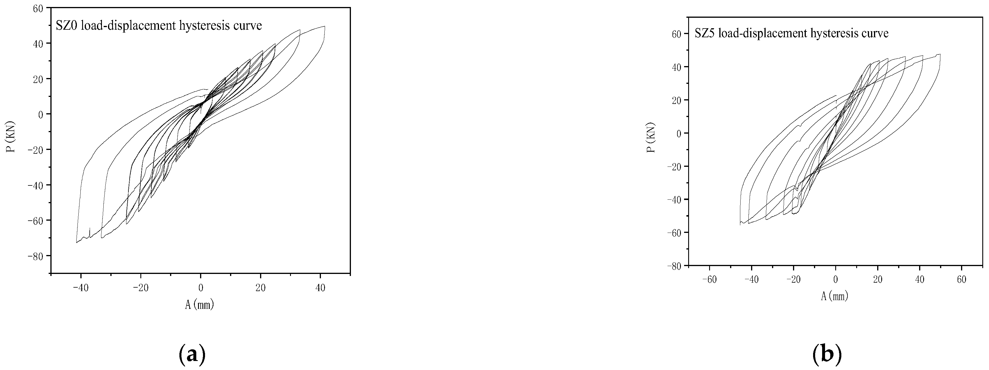
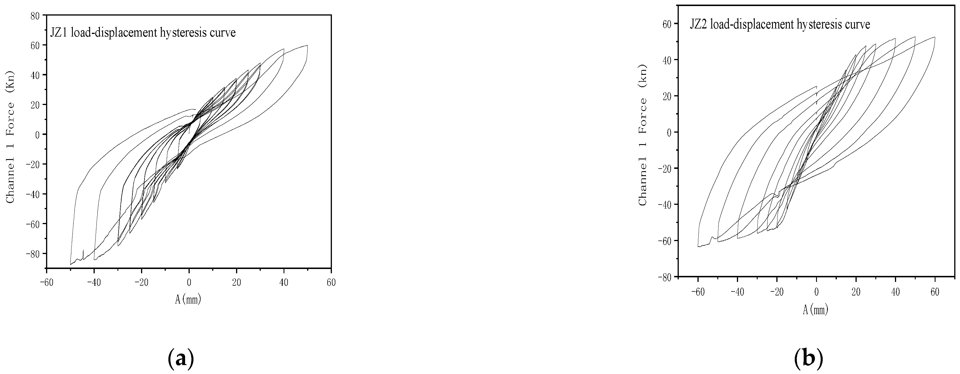
4.4. Analysis of Hysteresis Performance of Damaged Reinforced Concrete Components after Strengthening and Repairing

The hysteresis curve of a structure refers to the relationship curve between the acting force and displacement of the structure under the low-cycle repeated loading. It is a comprehensive reflection of the seismic performance of the structure and the main basis for the analysis of the structure’s seismic elasto-plastic dynamic response. After strengthening with steel plates and carbon fiber cloth, the load-displacement hysteresis curves of specimens are shown in the following figures, where the vertical axis represents the horizontal load at the top layer, and the horizontal axis represents the lateral displacement at the top layer. As shown in Figure 8, SL0 and SL5 are reference beams, and Figure 9 shows the load-displacement hysteresis curves of JL1 and JL2, which are strengthened by steel plates and carbon fiber cloth, respectively.
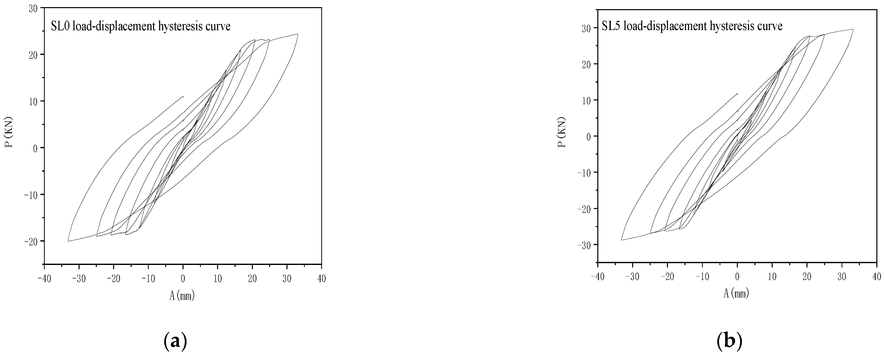
  • For specimens with different reinforcement ratios, the load-displacement hysteresis curves measured in the test can be compared. It can be seen that increasing the longitudinal reinforcement ratio significantly improves the hysteresis characteristics and the ductility of the components. The area enclosed by the hysteresis loop for each cyclic load increases, the pinch effect is alleviated, energy dissipation capacity increases, and stiffness increases, which is beneficial to seismic resistance.
  • By observing the hysteresis curve, the steel plate-strengthened beam exhibits a certain pinch effect at the lower level of loads, and its hysteresis fullness is slightly worse than that of the carbon-fiber-strengthened beam.
  • During the displacement-controlled cyclic loading process, the maximum load and the area enclosed by the hysteresis loop in the second cycle are significantly smaller than those in the first cycle, indicating that the specimens experienced the significant damage during the first positive and negative loading processes. Both carbon fiber-strengthened beams and steel plate-strengthened beams show this same characteristic.
Figure 10 shows the load-displacement hysteresis curves of reference column, and Figure 11 shows the load-displacement hysteresis curves for JZ1 and JZ2 (axial compression ratio of 0.2) reinforced with steel plates and carbon fiber, respectively.
  • Comparison of the load-displacement hysteresis curves measured at different axial compression ratios shows that there is a significant difference between high and low axial compression ratios for hysteresis characteristics and ductility of the members. The area enclosed by the repeated load hysteresis loops of the columns with higher axial compression ratios increases, the pinching phenomenon is alleviated, the energy dissipation capacity increases, and the stiffness increases, which is beneficial for seismic resistance.
  • Steel-plate-strengthened columns exhibit a certain pinch effect at the lower loads, and their hysteresis fullness is slightly worse than that of carbon-fiber-strengthened columns.
  • During the displacement-controlled cyclic loading process, the maximum load and the area enclosed by the hysteresis loop in the second cycle are significantly smaller than those in the first cycle, indicating that the specimens experienced significant damage during the first positive and negative loading processes. This characteristic is present in both carbon-fiber-strengthened columns and steel-plate-strengthened columns.

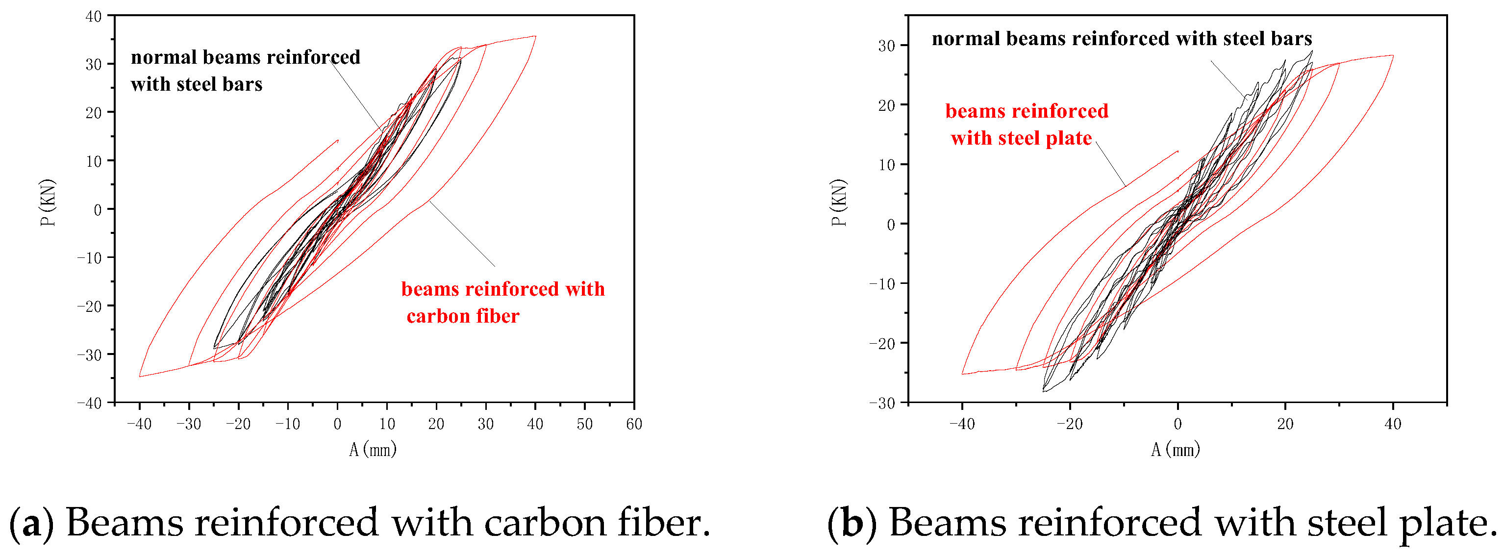
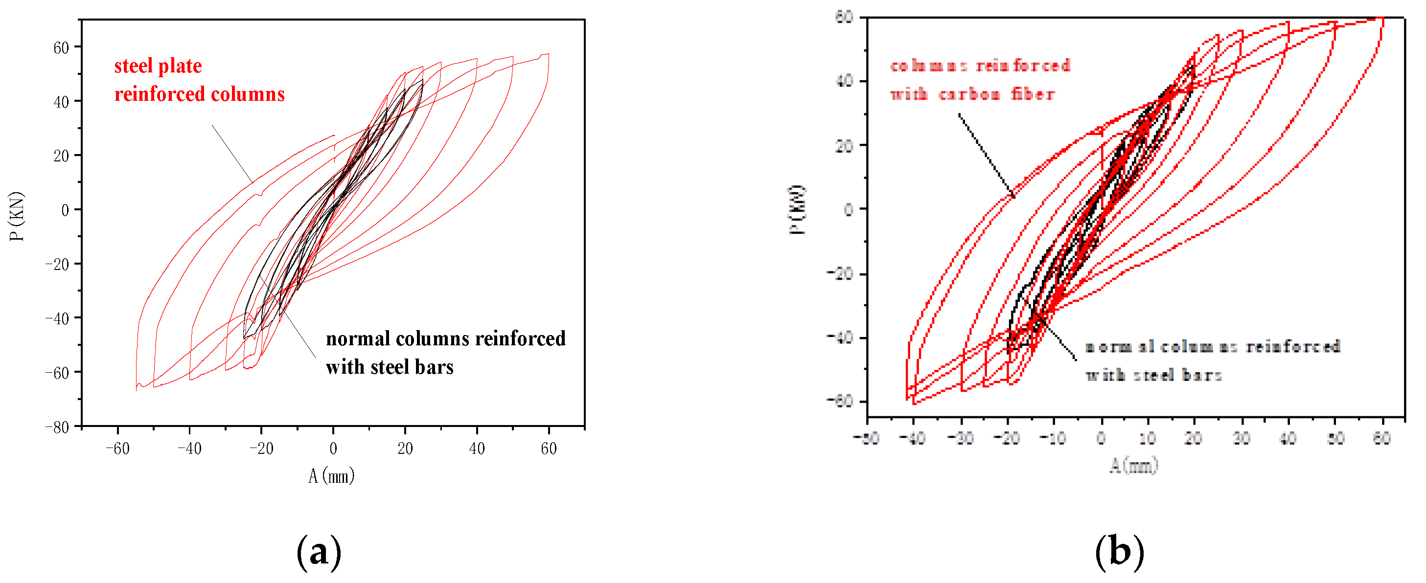
4.5. Comparison of Hysteresis Performance between Control Specimens and Reinforced Specimens after Repair

The following figure shows the measured values of the relationship curve between the load of the test piece and the deflection at a distance of 1500 mm from the beam base, with the horizontal axis representing the deflection (mm) and the vertical axis representing the load (kN). Figure 12 shows the comparison of load-displacement hysteresis curves of reinforced beams with different reinforcement ratios (Buildings 14 01102 i005 under different actions, and Figure 13 compares the hysteretic performance of columns with different reinforcement methods under an axial compression ratio of 0.2.
  • In terms of carrying capacity, deformation, hysteretic energy dissipation characteristics, and ductility, the hysteretic characteristics and ductility of the reinforced components are significantly improved. The area surrounded by hysteresis loops in each repetitive loading increases, skew collapse is reduced, and energy dissipation capacity increases.
  • Compared with the control components in terms of carrying capacity, deformation, hysteretic energy dissipation characteristics, and ductility, the hysteretic characteristics and ductility of the reinforced components are greatly improved. The area enclosed by the hysteresis loop of each reinforced column in each repeated load is increased, the phenomenon of skew collapse is alleviated, and energy dissipation capacity is improved in favor of seismic performance.
  • By comparing carbon-fiber-reinforcing steel with steel-plate-reinforcing steel, it can be found that carbon-fiber-reinforcing steel has a strong energy dissipation capacity.

5. Conclusions

Using reinforced concrete beams with different reinforcement ratios and reinforced concrete columns under different axial compression ratios, conduct horizontal low-cycle repeated load testing on the specimens; after damage, beams and columns are strengthened and repaired by bonding steel plates and carbon fiber cloth, and subjected to secondary loading tests. By analyzing the skeleton curves and hysteresis curves of the tested components, the mechanical properties of the components are studied, and the effects of different strengthening and repair methods on the seismic performance of the structure are discussed. The following conclusions are drawn:
  • The comparison of the experimental data in this study can verify the basic specification of structural design, i.e., increasing the longitudinal reinforcement ratio of beams can significantly improve the hysteresis characteristics and ductility of members, increase the area surrounded by hysteresis lines during each repetitive loading, reduce the clamping effect, and improve the energy dissipation capacity, so as to improve the seismic performance of the building.
  • The different axial compression ratios result in the significant difference in the hysteresis characteristics and ductility of reinforced concrete columns. Columns with a larger axial compression ratio have an increased area enclosed by the hysteresis loop during each repeated load, alleviated pinching effect, and increased energy dissipation capacity, which are beneficial to earthquake resistance.
  • Compared with the control beam, the carbon-fiber-reinforced beam has a bearing capacity increased by 1.29 times, ductility increased by 1.31 times, and capacity of earthquake energy dissipation increased by 1.59 times. Compared with the control beam, the steel-plate-reinforced beam has a bearing capacity increased by 1.14 times, ductility increased by 1.1 times, and capacity of earthquake energy dissipation capacity increased by 1.31 times. The seismic performance of carbon-fiber-reinforced beams is superior to that of steel-plate-reinforced beams.
  • Compared with the control column, the carbon-fiber-reinforced column has a bearing capacity increased by 1.15 times, ductility increased by 1.12 times, and capacity of earthquake energy dissipation increased by 1.45 times. Compared with the control column, the steel-plate-reinforced column has a bearing capacity increased by 1.1 times, ductility increased by 1.07 times, and capacity of earthquake energy dissipation capacity increased by 1.02 times. The seismic performance of carbon-fiber-reinforced columns is superior to that of steel-plate-reinforced columns.
  • The plastic hinge region of the components is mainly concentrated in the lower part of the beams and columns, within approximately the width of one component. Therefore, reinforcement only needs to be carried out in this area according to the calculated reinforcement amount. The reinforcement range only needs to be taken along the lower part of the beams and columns, covering one-third of the component length, which can effectively prevent the generation of shear failure. There is no need for reinforcement in other areas, which can effectively reduce the reinforcement amount.
  • Reasonable reinforcement methods can effectively improve the seismic performance of structures. From the above research, it can be seen that carbon fiber reinforcement has better effects than steel plate reinforcement, and can achieve better reinforcement effects.

Author Contributions

Conceptualization, G.N.; methodology, G.N.; software, W.Z. and C.S.; formal analysis, Z.W., W.Z.; investigation, Z.W; resources, C.S. and W.Z.; data curation, G.N.; writing—original draft preparation, G.N.; writing—review and editing, W.Z. and B.L.; visualization, B.L.; supervision, B.L. All authors have read and agreed to the published version of the manuscript.

Funding

The research is supported by the Natural Science Foundation of Hebei Province, grant number 10276903D.

Data Availability Statement

The data that support the findings of this study are available on request from the author Guowei Ni, upon reasonable request.

Conflicts of Interest

The authors declare no conflict of interest.

References

  1. Quan, S.H. Study on Seismic Performance of Reinforced Concrete Beams and Columns with Carbon Fiber. Ph.D. Thesis, Tianjin University, Tianjin, China, 2017. (In Chinese). [Google Scholar]
  2. GB 50608—2020; Standard for Technical Specifications of Fiber-Reinforced Composite Materials. China Planning Press: Beijing, China, 2020. (In Chinese)
  3. Liu, M.; Yin, X.G. Finite element dynamic analysis of reinforced concrete beams strengthened with viscoelastic dampers. J. Chongqing Univ. (Nat. Sci. Ed.) 2005, 28, 140–146. (In Chinese) [Google Scholar]
  4. Sheng, G.Y. Study on Seismic Performance of Reinforced Concrete Shear Walls Strengthened with Viscoelastic Dampers. Master’s Thesis, Tongji University, Shanghai, China, 2010. (In Chinese). [Google Scholar]
  5. Xie, Z.Y.; Deng, W.S. Finite element analysis of concrete beams strengthened with viscoelastic dampers. Henan Build. Mater. 2008, 6, 21–23. (In Chinese) [Google Scholar]
  6. Guo, M.; Liu, P. Calculation of flexural bearing capacity and section stiffness of double-sided steel plate-strengthened concrete slabs. J. Shandong Jianzhu Univ. 2008, 23, 47–56. (In Chinese) [Google Scholar]
  7. Yu, J.; Kuang, Y.H. Finite element analysis of concrete frame nodes strengthened with viscoelastic dampers. Archit. Technol. 2010, 11, 1051–1053. (In Chinese) [Google Scholar]
  8. Liu, Z.X. Experimental Study on the Mechanical Behavior of H-Shaped Steel Columns Strengthened with Carbon Fiber. Master’s Thesis, Hunan University, Changsha, China, 2020. (In Chinese). [Google Scholar]
  9. Zhang, N.W. Simplified calculation method for flexural bearing capacity of prestressed concrete beams strengthened with steel plates. Struct. Eng. 2021, 37, 60–64. [Google Scholar]
  10. Shahawy, M.; Chaallal, O.; Beitelman, T.E.; El-Saad, A. Flexural strengthening with carbon fiber-reinforced polymer composites of preloaded full-scale girders. ACI Struct. J. 2001, 98, 735–742. [Google Scholar]
  11. Lu, Z.D.; Hong, T. Seismic testing of low reinforcement concrete beam-slab-column nodes reinforced with carbon fiber-reinforced polymer. J. Tongji Univ. 2003, 31, 18–21. (In Chinese) [Google Scholar]
  12. Wang, W.W. Study on Flexural Performance of Fiber Composite Reinforced Concrete Beams. Ph.D. Thesis, Dalian University of Technology, Dalian, China, 2003. (In Chinese). [Google Scholar]
  13. Liu, L.G. Study on Flexural Mechanical Properties of Carbon Fiber Reinforced Concrete Beams. Master’s Thesis, Shandong University, Jinan, China, 2004. (In Chinese). [Google Scholar]
  14. Pan, Z.H.; Li, A.Q. Static elastic-plastic analysis of external steel reinforced concrete columns strengthened with fiber model. J. Southeast Univ. (Nat. Sci. Ed.) 2009, 39, 552–556. (In Chinese) [Google Scholar]
  15. Wang, S.Y.; Liu, F. Experimental study on fiber cloth reinforced concrete pipes damaged by earthquake. J. Shenyang Jianzhu Univ. 2010, 26, 216–222. (In Chinese) [Google Scholar]
  16. Xu, C.X.; Lu, M.X. Experimental study on seismic performance of carbon fiber cloth reinforced steel reinforced concrete columns damaged by earthquake. China Civ. Eng. J. 2016, 49, 51–56. (In Chinese) [Google Scholar]
  17. Xu, C.X.; Wang, C.F. Experimental study on seismic performance of carbon fiber cloth reinforced steel reinforced concrete frame node damaged by earthquake. Earthq. Resist. Eng. Retrofit. Methodol. 2018, 40, 110–116+130. (In Chinese) [Google Scholar]
  18. Zyeh, J. Engthening of concrete structures with carbon fiber-reinforced polymer and results from nondestructive evaluation: Repair, Rehabilitation, and maintenance of concrete structures, and innovations in design and construction. In Proceedings of the 4th Intemational Conference, Seoul, Republic of Korea, 26–29 September 2000; pp. 999–1026. [Google Scholar]
  19. Kou, J.L.; Zheng, D.D. Experimental study on the bending performance of damaged concrete beams without web reinforcement reinforced with high ductile concrete under repeated loading. Vib. Shock. 2021, 40, 279–289. (In Chinese) [Google Scholar]
  20. Deng, M.K.; Li, Q.Q. Experimental study on shear performance of RC beams reinforced with high ductile concrete. Eng. Mech. 2020, 37, 55–63. (In Chinese) [Google Scholar]
  21. Huang, Z.Y. Analysis of reinforcement methods for reinforced concrete structures. Eng. Constr. 2023, 55, 43–47. (In Chinese) [Google Scholar]
  22. Pan, X.L.; Liu, X.Q. Study on the seismic performance level of reinforced concrete frames with fibre cloth reinforced infill walls. Sci. Technol. Eng. 2023, 23, 10459–10468. (In Chinese) [Google Scholar]
  23. Wang, H.T.; Zhu, C.Y. Effects of anchorage method and prestressing level on flexural performance of reinforced concrete beams reinforced with CFRP plates. J. Hohai Univ. (Nat. Sci. Ed.) 2023, 51, 104–110. (In Chinese) [Google Scholar]
  24. American Concrete Institute. Building Code Requirements for Structural Concrete and Commentary; American Concrete Institute: Detroit, MI, USA, 2008. [Google Scholar]
  25. Yao, W.C. Overall stability analysis of I-shaped simply supported steel beams with shuttle deformation cross-section. Master’s Thesis, Hunan University, Changsha, China, 2010. (In Chinese). [Google Scholar]
  26. Zhou, C.Y.; Yu, Y.A. Experimental study on flexural performance of reinforced concrete narrow beams reinforced with side hung mixed-anchored carbon fiber fabric. J. Build. Struct. 2023, 44. (In Chinese) [Google Scholar] [CrossRef]
Figure 1. Model of samples of frame beams and column ends. (a) Model of frame beam end specimen. (b) Model of frame column end specimen.
Buildings 14 01102 g001
Figure 2. Detail of reinforcing steel work (unit: mm). (a) Beam elements reinforcement detailing. (b) Column component reinforcement detailing.
Buildings 14 01102 g002
Figure 3. Mechanical testing and simulation (MTS) power system device diagram.
Buildings 14 01102 g003
Figure 4. Load displacement method for load mixing control.
Buildings 14 01102 g004
Figure 5. Drawings of steel, carbon fiber reinforcement (unit: mm). (a) Steel reinforcement. (b) Carbon fiber reinforcement.
Buildings 14 01102 g005
Figure 6. Skeleton curve of the beam reinforcement. (a) SL0—comparison beam. (b) JL2—reinforced beam.
Buildings 14 01102 g006
Figure 7. Skeleton curve of reinforced columns. (a) SZ0—comparison column. (b) JZ2—reinforced column.
Buildings 14 01102 g007
Figure 8. Damaged beams in the load-displacement hysteretic dashed. (a) SL0—load-displacement hysteresis curve. (b) SL5—load-displacement hysteresis curve.
Buildings 14 01102 g008
Figure 9. Reinforced beams in the load-displacement hysteretic dashed. (a) JL1—load-displacement hysteresis curve. (b) JL1—load-displacement hysteresis curve.
Buildings 14 01102 g009
Figure 10. Damage columns in the load-displacement hysteretic dashed. (a) SZ0—load-displacement hysteresis curve. (b) SZ5—load-displacement hysteresis curve.
Buildings 14 01102 g010
Figure 11. Reinforced columns in the load—displacement hysteretic dashed. (a) JZ1—load-displacement hysteresis curve. (b) JZ2—load-displacement hysteresis curve.
Buildings 14 01102 g011
Figure 12. Comparison of beams. (a) Beams reinforced with carbon fiber. (b) Beams reinforced with steel plate.
Buildings 14 01102 g012
Figure 13. Comparison of columns. (a) Columns reinforced with carbon fiber. (b) Columns reinforced with steel plate.
Buildings 14 01102 g013
Table 1. Common reinforcement methods for concrete structures.
Reinforcement MethodReinforcement PrincipleApplicable Components
Enlarging cross-sectionEnlarging cross-sectionBeams, slabs, columns
Bonding steel platesIncreasing reinforcementBeams, slabs, columns
Bonding carbon fiber clothIncreasing reinforcementBeams, slabs, columns
Table 2. Beam and column specimen parameters and reinforcement methods.
NumberLongitudinal RibsReinforcement MethodNumberAxial
Compression
Ratio
Longitudinal RibsReinforcement Method
L04Buildings 14 01102 i00414/Z00.28Buildings 14 01102 i00414/
L14Buildings 14 01102 i00414/Z10.28Buildings 14 01102 i00414/
L24Buildings 14 01102 i00414/Z20.28Buildings 14 01102 i00414/
L34Buildings 14 01102 i00418/Z30.48Buildings 14 01102 i00414/
L44Buildings 14 01102 i00418/Z40.48Buildings 14 01102 i00414/
L54Buildings 14 01102 i00418/Z50.48Buildings 14 01102 i00414/
JL14Buildings 14 01102 i00414Steel plateJZ10.28Buildings 14 01102 i00414Steel plate
JL24Buildings 14 01102 i00414Carbon fiber clothJZ20.28Buildings 14 01102 i00414Carbon fiber cloth
JL34Buildings 14 01102 i00418Steel plateJZ30.48Buildings 14 01102 i00414Steel plate
JL44Buildings 14 01102 i00418Carbon fiber clothJZ40.48Buildings 14 01102 i00414Carbon fiber cloth
Table 3. Material properties of reinforcement bars.
Rebar Type Rebar
Diameter (mm)
Yield Strength
(Mpa)
Tensile Strength
(Mpa)
Elastic
Modulus
(×105 Mpa)
Elongation (%)
Buildings 14 01102 i0018235.6406.72.132.2
Buildings 14 01102 i00214440.9625.4224.3
Buildings 14 01102 i00318455.7649.8223.5
Table 4. Material properties of concrete.
PositionConcrete Strength GradeCube
Compressive Strength (Mpa)
Axial Compressive Strength (Mpa)Elastic Modulus (×104 Mpa)
Precast beams and columnsC3037.548.93
Table 5. Ductility of different reinforcement ratios and reinforcement method beams.
Reinforcement SituationReinforcement MethodYield Value
(mm)
Limit Value (mm)Damage Value (mm)Ductility
4Buildings 14 01102 i00414Steel plate2545552.2
Carbon fiber cloth2550602.4
4Buildings 14 01102 i00418Steel plate2550602.4
Carbon fiber cloth2550652.6
Table 6. Comparison of the ductility of different axial and different reinforcement method beams.
Axial Compression RatioReinforcement MethodYield Value (mm)Limit Value (mm)Damage Value (mm)Ductility
0.2Steel plate3050702.3
Carbon fiber cloth3055752.5
0.4Steel plate3060752.5
Carbon fiber cloth3065802.7
Table 7. Reinforcement rates in different ways in different beam energy values of the reinforcement.
Reinforcement SituationReinforcement MethodEnergy Consumption
(kN·mm)
4Buildings 14 01102 i00414Steel plate1291
Carbon fiber cloth1552
4Buildings 14 01102 i00418Steel plate1313
Carbon fiber cloth1606
Table 8. Energy value of columns on different axial and reinforcement methods.
Reinforcement SituationReinforcement MethodEnergy Consumption (kN·mm)
0.2Steel plate3220
Carbon fiber cloth4632.7
0.4Steel plate3358.5
Carbon fiber cloth4757.5
Disclaimer/Publisher’s Note: The statements, opinions and data contained in all publications are solely those of the individual author(s) and contributor(s) and not of MDPI and/or the editor(s). MDPI and/or the editor(s) disclaim responsibility for any injury to people or property resulting from any ideas, methods, instructions or products referred to in the content.

